Leaflet - AC Motor Drives VF series - Deutsche Messe...
10
AC Motor Drives VF series
Transcript of Leaflet - AC Motor Drives VF series - Deutsche Messe...

AC MotorDrivesVF series
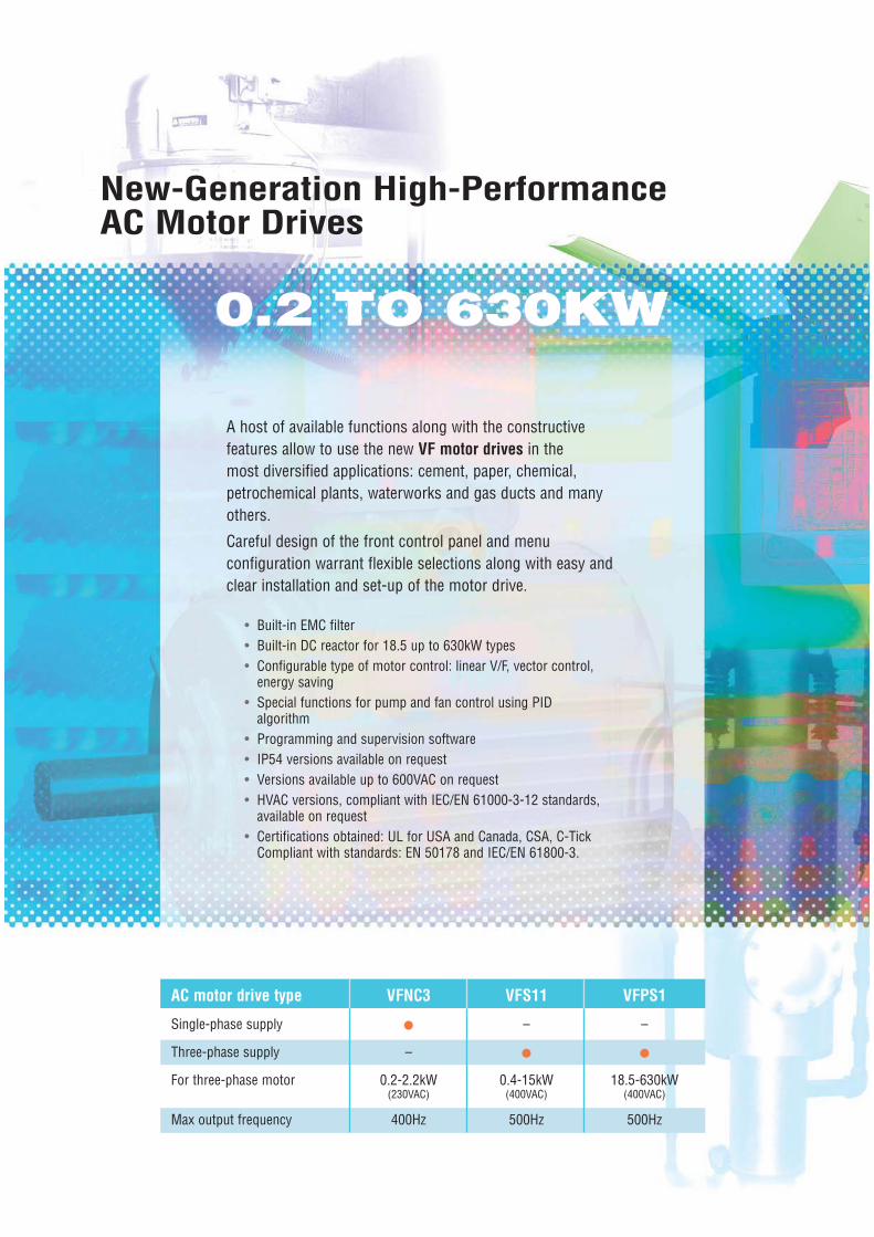
A host of available functions along with the constructivefeatures allow to use the new VF motor drives in the most diversified applications: cement, paper, chemical,petrochemical plants, waterworks and gas ducts and manyothers.
Careful design of the front control panel and menu configuration warrant flexible selections along with easy andclear installation and set-up of the motor drive.
New-Generation High-PerformanceAC Motor Drives
• Built-in EMC filter• Built-in DC reactor for 18.5 up to 630kW types• Configurable type of motor control: linear V/F, vector control,
energy saving• Special functions for pump and fan control using PID
algorithm• Programming and supervision software• IP54 versions available on request• Versions available up to 600VAC on request• HVAC versions, compliant with IEC/EN 61000-3-12 standards,
available on request• Certifications obtained: UL for USA and Canada, CSA, C-Tick
Compliant with standards: EN 50178 and IEC/EN 61800-3.
0.2 TO 630KW0.2 TO 630KW
AC motor drive type VFNC3 VFS11 VFPS1
Single-phase supply • – –
Three-phase supply – • •For three-phase motor 0.2-2.2kW 0.4-15kW 18.5-630kW
(230VAC) (400VAC) (400VAC)
Max output frequency 400Hz 500Hz 500Hz
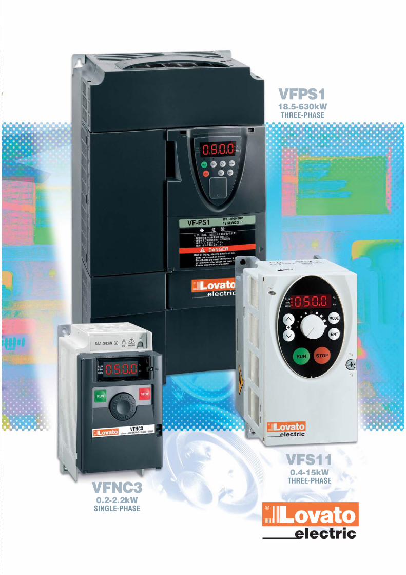
VFNC30.2-2.2kW
SINGLE-PHASE
VFS110.4-15kW
THREE-PHASE
VFPS118.5-630kWTHREE-PHASE

EXAMPLES OFAPPLICATION
ENERGY SAVINGThe new supervision of energy saving provides to optimise the outputefficiency for the utility (pumps, fans), even with low frequency valueusage.The effect of this function can be monitored by the built-in panel or bycommunication via protocol. See Fig. 1.
HIGH FREQUENCY NOISE AND HARMONIC DISTORTIONThe entire line up to 630kW has a built-in EMC filter, compliant withIEC/EN 61800-3 standards, first environment category 1, and makes itideal for applications where there is a need to give very particularattention to irradiated disturbances towards peripheral equipment. See Fig. 2.
DC REACTOR Built in the 18.5 to 75kW models and to be externally installed for the90kW model and over. It allows to drastically reduce harmonics producted by the motor drive and to improve the power factor.The DC reactor also permits to limit the current drawn by the motordrive to a maximum value of 110% of its rated current. See Fig. 3.
Food processing industryMachinery for bread, bakery and
fresh pasta, confectionary equipment, mixers and blenders,
flour and liquid dispensing equipment, etc.
Conveyance machineryProduct conveyor belts for
warehouses, tradebusinesses, etc.
PumpsFans, dryers, water purification
systems, waterworks, etc.
VF series motor drives can beused in a variety of applications in diversifiedindustrial and civil fields.
Output frequency (%)
Outp
ut p
ower
(%)
120
100
80
60
40
20
10 20 30 40 50 60 70 80 90 1000
Effect of advanced energy-saving modeEffect of advanced energy-saving mode
Damper control
V/F control
Advanced energy saving
Fig. 1
Frequency [MHz]
[dBuV]100
80
60
40
20
0.15 1 10 300
Effect of built-in filterEffect of built-in filter
Example of generated noise data
IEC/EN 61800-3 1st Environment Category C2
Fig. 2 Fig. 3
VFPS1(400V-30kW)
Input current 60.0AOutput current 59.7A
Conventional model(400V-30kW)
Input current 87.6AOutput current 59.7A
300
200
100
0iu(A
)
v1(V
)
-100
-200
-300
600
400
200
0
-200
-400
-600
Input current and voltage
300
200
100
0iu(A
)
v1(V
)
-100
-200
-300
600
400
200
0
-200
-400
-600
Input current and voltage
200
400
600 200
400
600
Input current
Effect of built-in reactorEffect of built-in reactor
AC motor drives V

Side by Side installationAll AC motor drives can be
installed without sideclearance for space saving.
Traditional installation withside clearance between AC
motor drives.
Medical and fitnessequipment
Equipment for fitness centresand for healthcare.
Vehicle washing machinesAutomatic car washing
equipment.
PackagingAutomatic and semi-automaticpackaging machines in cartons,
plastic bags or cases or withcellophane, etc.
Commercial ironing equipmentAutomatic machines used innumerous public stores and
service industries.
For the VF motor drive and PC communications (Microsoft®
Windows®98, 2000 and XP), a software is available and permits to:
• Modify parameters• Supervise the motor drive and the motor
• Create trend graphs• Print parameter changes.
software
F series
EASY KEYThe EASY key, on the control keypad of theVFNC3S... and VFPS1... models, permits to obtaina simplified access to different functions, such as:
Local/Remote: to switch between themotor and remote controls connected
to the digital/analog inputs of the localcommands available on board themotor drive.Quick Mode: to create a customisable menu with only specific
parameters for one’s own applicationand to lock out the modification of all
the others.
LESS INSTALLATION SPACE

VFNC3… TYPE• 200-240VAC single-phase supply• EMC suppressor built in for noise immunity
(IEC/EN 61800-3, 1° environment cat. C1,class B).
MCCB
+ +
-
-
VFNC3
Ry
DC reactor (DCL) ❶
Forward
Reverse
Low-speedsignal output
Voltage signal: 0...5V/0...10V (Current signal: 4...20mA)
External potentiometer (1...10k )
Meter
Preset-speed 1
Preset-speed 2
FLA
FLB
FLC
P24
F
R
S1
S2
P24
OUT
NO
CCFM CC VI P5
R/L1
S/L2
U/T1
V/T2
W/T3
P0 PA/+ PC/-
Frequencymeter
(ammeter)
Protective functionactivation output
Controlcircuit
Noisefilter
Powercircuit
7.5V-1mA(or 0...10V/4...20mA)
Single-phase power supply:220...240VAC - 50/60Hz
❶ The motor drive is supplied with the POand the PA/+ terminals shorted bymeans of a shorting bar.Before installing the DC reactor (DCL),remove the bar.
❷ When using the NO output terminal insource logic mode, short the P24 and OUT terminals.
❸ 1ph-240V models have noise filter inside.
❷
❸
Motor
MSingle-phase
VFS11… TYPE• 380-500VAC three-phase supply• EMC suppressor built in for noise immunity
(IEC/EN 61800-3, 1° environment cat. C2or 2° environment cat. C3, class A)
• Integrated dynamic braking circuit.
Three-phase
VFPS1… TYPE• 380-480VAC three-phase supply• EMC suppressor built in for noise immunity
(IEC/EN 61800-3, 1° environment cat. C2or 2° environment cat. C3, class A)
• Integrated dynamic braking circuit up to 220kW• Integrated DC reactor.
MY FUNCTIONIt is a function with which small programs can be madewith logic operations using the motor drive parameters.
My Function features:• Number of lines: 7• Number of instructions per line: 4• Number of total instructions: 28• Internal relays: 8• Internal counters: 2• Logic functions. ST, STN, AND, ANDN, OR,
ORN, SET, RSET, HOLD, ON/OFF delay timer• Comparators: EQ (equal to), NE (not equal to),
GT (greater than), GE (greater than or equal to), LT (less than), LE (less than or equal to) and ASUB (absolute value).
Three-phase
JOG DIALIt simplifies the programmingand control process of theVFNC3S through an intuitiveand congenial use.It also can be used as an
on-board potentiometer tochange the motor frequency.
❷
MCCB
+ +
-
-Meter
External potentiometer (1...10kW)(or input voltage signal across VIB-CC terminals: 0...10V)
Protectivefunctionactivationoutput
VFS11
Frequencymeter
(ammeter)
Power circuit
DC reactor (DCL) ❶ (option)
Forward
Reverse
Reset
Preset-speed 1
Preset-speed 2
Preset-speed 3
Braking resistor (option)
Low-speedsignal output
24VDC input
7.5V-1mA (or 4...20mA)
Voltage signal: 0...10V (Current signal: 4...20mA)
Speed reach signaloutput
Ry
R/L1
S/L2
T/L3
FLC
FLB
FLA
RY
RC
PLC
FM CC VIA VIB PP
P24
F
R
RES
S1
S2
S3
P24
OUT
NO
CC
U/T1
V/T2
W/T3
P0 PA/+ P PC/-
CC
Controlcircuit
Noisefilter
Three-phase power supply:380...500VAC - 50/60Hz
❶ The motor drive is supplied with the POand the PA/+ terminals shorted bymeans of a shorting bar.Before installing the DC reactor (DCL),remove the bar.
❷ When using the NO output terminal insource logic mode, short the P24 and OUT terminals.
❸ 600V models have no noise filter inside.
❸
Motor
M
Single-phase 0.2 to 2.2kW
Three-phase0.4 to 15kW
Three-phase18.5 to 630kW
❼ ❼❼
❽
Amm
eter
MCCB
R/L1
S/L2
T/L3
External potentiometer (1...10kOhm)or voltage signal between RR/S4 and CCA: 0...10V
Ammeter or voltmeter
PPFM RR/S4VI/IIRXCCAAM(OUT/1)
+DC -DC
PO PA/+ PB PC/-
U/T1
V/T2
W/T3
F
R
RES
S1
S2
S3
CC
P24/PLC
PWR
OUT1
OUT2
CC
NO
FLA
FLB
FLC
+SU
CC
Controlcircuit
(a)
Forward run signal
Reverse run signal
Reset
Preset speed 1
Preset speed 2
Preset speed 3
Default setting
Voltage signal: 0...10V
Voltage signal: 0...10Vor current signal: 4 (0)...20mA
Frequencymeter
VFPS1
Noisefilter
Maincircuit
Ammeter
Three-phase power source:380...480VAC - 50/60Hz
❶ ❹❻
❺
❸
❷Motor
M
Protectivefunctionactivationoutput
❶ The motor drive is shipped with the terminals POand PA/+ shorted with a bar (200V-45kW or smaller.400V-75kW or smaller)Remove the shorting bar when installing a DC reactor (DCL).
❷ The DC reactor is built in for models 200V-11kW~45kW and 400V-18.5kW~75kW.
❸ The noise filter is built in for models 200V-45kW or smaller and all of 400V.
❹ External braking resistor (option). Dynamic braking drive circuit built-in (GTR7) as standard for models 220kW or smaller.
❺ To supply a DC power, connect the cables to the PA/+ and PC/- terminals.
❻ If a DC power supply is used to operate the motor drive (200V: 18.5kW or more, 400V: 22kW or more), be sure to contact our Customer service (Tel. +39 035 4282422; email: [email protected]), because a current limiting circuit is required in such a case.
❼ The functions assigned to terminals OUT1, VI/II and RR/S4 can be switched by changing parameter settings.
❽ For PWR connection conforming to safety standards, refer to the user's manual.

Star-delta startersReversing and changeover contactors
Direct-on-line starters
O t h e r s t a r t e r s f o r e l e c t r i
AC motor drivesO r d e r c o d e
SINGLE-PHASE SUPPLY 200-240VAC 50/60HZVFNC3S 2002PL W 1.4 0.20 0.25 72 143 102 1 0.900VFNC3S 2004PL W 2.4 0.40 0.54 72 143 121 1 1.000VFNC3S 2007PL W 4.2 0.75 1 72 143 131 1 1.300VFNC3S 2015PL W 7.5 1.50 2 117 142 156 1 2.000VFNC3S 2022PL W 10.0 2.20 3 117 142 156 1 2.000
Order Current ❶ 3-phase motor Dimensions Q.ty per Weightcode power A B C pkg
[A] [kW] [HP] [mm] [n°] [kg]
VFNC3
THREE-PHASE SUPPLY 380-480VAC 50/60HZ ➌
VFPS1 4185PL WP 41 18.5 25 230 409 191 1 22.200VFPS1 4220PL WP 48 22 30 240 420 212 1 23.700VFPS1 4300PL WP 66 30 40 240 550 242 1 32.500VFPS1 4370PL WP 79 37 50 240 550 242 1 32.800VFPS1 4450PL WP 94 45 60 320 630 290 1 54.000VFPS1 4550PL WP 116 55 75 320 630 290 1 54.000VFPS1 4750PL WP 160 75 100 320 630 290 1 54.000VFPS1 4900PC WP 179 90 125 310 680 375 1 100.000VFPS1 4110KPC WP 215 110 150 310 680 375 1 100.000
VFPS1
THREE-PHASE SUPPLY 380-440VAC 50HZ / 380-480VAC 60HZ ➍
VFPS1 4132KPC WP 259 132 200 350 782 375 1 108.000VFPS1 4160KPC WP 314 160 250 330 950 377 1 118.000VFPS1 4220KPC WP 427 220 350 430 950 377 1 161.000VFPS1 4250KPC WP 481 250 400 585 950 377 1 194.000VFPS1 4280KPC WP 550 280 450 585 950 377 1 204.000VFPS1 4315KPC WP 616 315 500 585 950 377 1 204.000VFPS1 4400KPC WP 759 400 600 880 1150 377 1 302.000VFPS1 4500KPC WP 941 500 700 880 1150 377 1 320.000VFPS1 4630KPC WP 1181 630 1000 1108 1150 377 1 462.000
THREE-PHASE SUPPLY 380-500VAC 50/60HZ ➋
VFS11 4004PL WP 1.5 0.4 0.54 105 130 150 1 2.100VFS11 4007PL WP 2.3 0.75 1
105 130 150 12.100
VFS11 4015PL WP 4.1 1.5 2 2.200VFS11 4022PL WP 5.5 2.2 3
140 170 150 13.100
VFS11 4037PL WP 9.5 4.0 5 3.200VFS11 4055PL WP 14.3 5.5 7.5
180 220 170 15.900
VFS11 4075PL WP 17 7.5 10 6.700VFS11 4110PL WP 27.7 11 15
245 310 190 111.000
VFS11 4150PL WP 33 15 20 11.500
VFS11
B
AC
❶ Operation up to 50°C without derating.➋ 240VAC and 600VAC three-phase available on request.➌ 240VAC (VFPS1 4110KPC WP excluded) and 600VAC three-phase available on request.➍ 600VAC three-phase available on request.
Soft starters
c m o t o r s
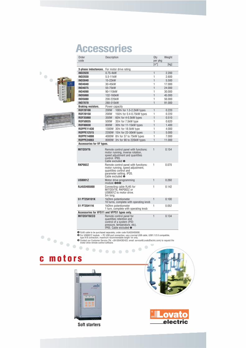
Accessories
3-phase inductances. For motor drive ratingIND2020 0.75-4kW 1 2.200IND2030 5.5-11kW 1 2.600IND3040 15-22kW 1 5.500IND4040 30-45kW 1 17.000IND4075 55-75kW 1 24.000IND4090 90-110kW 1 30.000IND5060 132-160kW 1 45.000IND5080 200-220kW 1 56.000IND7070 280-315kW 1 91.000Braking resistors. Power capacityROF20100 200W 100N for 1.5-2.2kW types 1 0.220ROF20150 200W 150N for 0.4-0.75kW types 1 0.220ROF35060 350W 60N for 4-5.5kW types 1 0.510ROF50035 500W 35N for 7.5kW type 1 0.620ROF80030 800W 30N for 11-15kW types 1 1.400ROPPE11430 1300W 30N for 18.5kW type 1 4.000ROPPE12515 2200W 15N for 22-30kW types 1 5.000ROPPE14008 4000W 8N for 37 to 75kW types 1 7.000ROPPE24003 8000W 3N for 90 to 220kW types 1 11.000Accessories for VF types.
Order Description Qty Weight code per pkg
[n°] [kg]
MITOSVT6 Remote control panel with functions: 1 0.154motor running, inverse rotation,speed adjustment and quantitiescontrol. IP65.Cable excluded ❶
RKP002Z Remote control panel with functions: 1 0.070motor running, speed adjustment,quantities control andparameter setting. IP20.Cable excluded ❶
USB001Z Motor drive programming 1 0.260module ❶❷❸
RJ45SH05000 Connecting cable RJ45 for 1 0.142MITOSVT6, RKP002Z orUSB001Z to motor drive.5m long.
51 PT25H101K 1kOhm potentiometer 1 0.10010 turns, complete with operating knob
51 PT35H11K 1kOhm potentiometer 1 0.0521 turn, complete with operating knob
Accessories for VFS11 and VFPS1 types only.MITOSVT6ECO Remote control panel for 1 0.134
quantities retention andcontrol of a system (PID:pressure, temperature, etc).IP65. Cable excluded ❶
❶ RJ45 cable to be purchased separately; order code RJ45SH05000.❷ For USB001Z module → PC USB port connection, use a normal USB cable, USB1.1/2.0 compatible,
type A-B connection, maximum recommendable length 1m only.❸ Contact our Customer Service (Tel. +39 0354282422; email: [email protected]) to request the
motor drive remote control software.

Main characteristicsBuilt-in surge suppressor Class B Class A Class ABuilt-in DC reactor – – •Instantaneous overload 200% 200% 135%
(0.5s) (0.5s) (2s)Overload for 60 seconds 150% 150% 120%Low speed torque 150% 1Hz 150%1Hz 130% 1HzIntegrated dynamic braking circuit – • (18.5-220kW)Capacitor pre-charge circuit • • •DC-bus access • • •Maximum output frequency 400Hz 500Hz 500Hz
InterfaceDigital inputs 4+1 ❶ 6+2 ❶ 6+1 ❶
Digital outputs 1 2 1Static relay outputs 1 1 2Analog inputs 0-10VDC/4-20mA 1 2 ❶ 2+1 ❶
Analog outputs 0-10VDC/4-20mA 1 1 2I/O logic PNP or NPN switchable – • •Serial port RS485 TTL RS485 (n° 2)
Front keyboardDisplay • • •Operation keys • • •START/STOP keys • • •Speed adjustment keys • • •Potentiometer • • –
ProtectionsOver-current • • •Over-voltage • • •IN/OUT phase failure • • •Motor overload • • •Drive overload • • •Dynamic braking resistor overload – • •Drive over-heating • • •Over-torque • • •Output short circuit and earth leakage protection • • •
FunctionsConstant motor torque control V/f • • •Variable motor torque control • • •Automatic motor torque boost control • • •Sensorless vector (speed) control • • •Closed loop motor control – – •Preset speed operation 15 15 15PID function • • •Regenerative energy control • • •DC injection braking • • •Auto-tuning • • •Auto-restart and speed adjustment • • •Frequency potentiometer (speed adjustmentvia 2 external pushbuttons) • • •Different motor controls with ind. sets of parameter 2 2 4Automatic fast speed search and detection • • •Communication protocol Toshiba-Modbus Toshiba-Modbus Toshiba-ModbusOverride function – • –Automatic stopping after continuous runningat minimum frequency (Sleep function) • • •PTC input – Optional board IntegratedSpeed maintained operation during alarmconditions (Fire control functions) – • •
❶ Input configurable as analog or digital.
VFNC3 VFS11 VFPS1
General characteristics

2009
Digital multimeters andpower analyzers DMG series
Switching power supplies
Signal towers and beacons
Switch disconnectors16 to 1250A
SwitchSwitch
PL
AN
ET
DinDin
PL
AN
ET
LogicLogic
PL
AN
ET
I
OF
F
0
ON
CN25.10
A1
13
513 (7)
A2
24
614 (8)
24V
50/60Hz
Modular contactor
13
513(7)
2
EARTHLEAKAGERELA
R1
TEST
RESET
FUNCTIO
autorese tx1
Inx
Inx1
manrese
tx
0,2
0,
11,
2
2,O
TRI
In(A
t(sec0,00,00,
0,0,
0,
0,
InSCALESETTIN
autorese tx1
Inx
Inx1
manrese
tx
Inx0,
autorese tx1
Inx
Inx1
manrese
tx
Inx0,
autorese tx1
Inx
Inx1
manrese
tx
Inx0,
Inx0,
Inx0,
Inx
Inx1
MON
ENT
RUN
STOP
BC
AUTOMATIC BATTERY CHARGED
POWER ON
CHARGE
ALARM
LOWBATTERYVOLTAG
BATTERYFUSEBLOW
BATTERYNOTCONNECTE
BATTERYPOLARITYINVERTE
I CHARGE30
4
5
67 8
9
100
12V=-3
24V=-2.5
PO
WE
R22
0-24
0V~
50-6
0Hz
AL
AR
M O
UT
BA
TT
ER
Y
LN
__
+
BA
TT
ER
YF
US
E 6
,3A
AT
AUTOMATICTRANSFERSWITCHCONTROLLE
LINE
LL
LH
LINE
LL
LH
ALAR
TES
TES
AU
MA
OF
RESE
O
OF
O
OF
OWITHDRAW
TRI
LOA
O
WITHDRAW TRI
A01LOWBATTERYVOLTAG
A02HIGHBATTERYVOLTAG
A03LINE1SWITCHFAUL
A04LINE2SWITCHFAUL
A05LINE1WRONGPHASESEQ
A06LINE2WRONGPHASESEQ
A07LOADNOTPOWEREDT.OU
A08GENERATORNOTREAD
A09EMERGENCYSTO
Modular contactors
Time relays
Protection relays
Level control relays
Earth leakage relays
Motor protection circuitbreakers
Switch disconnectors
Contactors
Motor protection relays
Electromechanical starters
Control and signalling units
Limit, micro and foot switches
Rotary cam switches
Contactors
The
prod
ucts
des
crib
ed in
this
pub
licat
ion
are
subj
ect t
o be
revi
sed
or im
prov
ed a
t any
mom
ent.
Cata
logu
e de
scrip
tions
and
deta
ils, s
uch
as te
chni
cal a
nd o
pera
tiona
l dat
a, d
raw
ings
, dia
gram
s an
d in
stru
ctio
ns, e
tc.,
do n
ot h
ave
any
cont
ract
ual v
alue
. In
add
ition
, pro
duct
s sh
ould
be
inst
alle
d an
d us
ed b
y qu
alifi
ed p
erso
nnel
and
in c
ompl
ianc
e w
ith th
e re
gula
tions
in fo
rce
for
elec
trica
l sys
tem
s in
ord
er to
avo
id d
amag
es a
nd s
afet
y ha
zard
s.PD
35 G
B 12
09
www.LovatoElectric.comwww.LovatoElectric.com
LOVATO Electric offices in the world
www.LovatoElectric.comLOVATO ELECTRIC S.P.A.CONTROL SOLUTIONS FOR INDUSTRYVIA DON E. MAZZA, 12 - 24020 GORLE (BERGAMO) ITALYTel. +39 035 4282111 Fax +39 035 4282200E-mail: [email protected] Sales Department: Tel. +39 035 4282354 - Fax +39 035 4282400
United KingdomLOVATO (UK) LTDTel. +44 08458 110023www.Lovato.co.uk
Czech RepublicLOVATO S.R.O.Tel. +420 382 265482www.Lovato.cz
GermanyDELTEC LOVATO GmbHTel. +49 7237 1733www.DeltecLovato.de
USALOVATO ELECTRIC INCTel. +1 757 545 4700www.LovatoUsa.com
SpainLOVATO ELECTRIC S.L.Tel. +34 938 454649www.LovatoElectric.es
CanadaLOVATO ELECTRICCORPORATIONTel. +1 450 681 9200www.Lovato.ca
PolandLOVATO ELECTRIC SP. Z O.O.Tel. +48 71 7979010www.LovatoElectric.pl
MexicoLOVATO ELECTRICDE MEXICO, S.A. DE C.V.Tel. +52 555 3415662www.LovatoElectric.com.mx
Sinc
e
1922
Present in over 80 countries
Metering instruments andcurrent transformers
Soft starters
AC motor drives
Automatic power factorcontrollers
Automatic battery chargers
Automatic transfer switchcontrollers
Programmable logic relays
Switching power supplies
Expansion modules andaccessories


![[PPT]Slide 1 · Web viewDC and AC Motor Drives Induction Motor Drives: Stator Voltage Control The stator voltage can be varied by three-phase ac voltage controllers, voltage-fed variable](https://static.fdocuments.in/doc/165x107/5add0e687f8b9a4a268d007a/pptslide-1-viewdc-and-ac-motor-drives-induction-motor-drives-stator-voltage-control.jpg)