Leadership in fusible circuit protection solutions€¦ · Leadership in fusible circuit protection...
12
Leadership in fusible circuit protection solutions Bussmann series Third rail fuse links application guide
Transcript of Leadership in fusible circuit protection solutions€¦ · Leadership in fusible circuit protection...
Leadership in fusible circuit protection solutions
Bussmann seriesThird rail fuse links application guide
Eaton’s Bussmann business has over 100 years
of experience in the design and manufacture
of fuse links.
Utilising a global network of engineering, manufacture and distribution Eaton’s
Bussmann business is able to draw upon a wealth of knowledge.
As railway systems and standards have changed, so have the protection needs.
Eaton’s Bussmann business is continually developing new and improving existing
designs to meet these ever changing requirements. The experience of Eaton’s
Bussmann business in protecting semiconductor devices has proved invaluable as
train systems have moved to power based converters for the variable speed motor
drives and also for auxiliary power conversion.
Throughout its history, Eaton’s Bussmann business has been continually chosen to
supply the industry’s key train manufacturers. Eaton’s Bussmann series products can
be found all across the globe and are extensively used across the America, Europe
and Asia and numerous other countries.
This application guide has been developed using the knowledge obtained from
recommending fuse links to the traction industry for many years across a variety of
applications in a multitude of locations.
2 EATON Bussmann series third rail fuse links application guide
Table of contents
Bussmann series traction capability overview 4 - 5
Introduction 6
Fuse link protection in third rail systems 7Power supply 7Train borne power circuit 7Train power conversion equipment 7On-board systems 7Shed supplies 7
Protection of main power systems 7Continuous operation 7Fault situations 7
Selection of fuse links for power circuit protection 8 - 11Continuous operation 8 - 9Fault situations 9 - 10Selection of physical style 11
3EATON Bussmann series third rail fuse links application guide

4 EATON Bussmann series third rail fuse links application guide
5EATON Bussmann series third rail fuse links application guide
Introduction
Third rail railway systems are used for many urban,
metro and subway railways throughout the world. They
are characterised by the power being supplied by a live
outside third rail and returned through the wheels to
the earthed running rails. Alternatively, a center fourth
rail, isolated from the running rails, may be used for the
return current path.
Third rail systems are typically supplied by direct current (DC) where the supply voltage is under 1000Vdc. For sub surface systems the nominal supply voltage will be between 650 and 750Vdc.
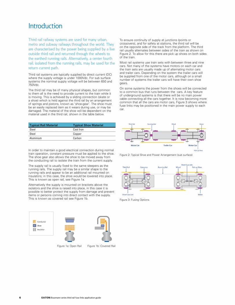
The third rail may be of many physical shapes, but common to them all is the need to provide current to the train while it is moving. This is achieved by a sliding connection (skate or a shoe) which is held against the third rail by an arrangement of springs and pistons, known as ‘shoe-gear’. The shoe must be an easily replaced item as it wears during use, or may be damaged. The material of the shoe will be dependent on the material used in the third rail, shown in the table below.
Typical Rail Material Typical Shoe MaterialSteel Cast IronSteel CopperAluminium Carbon
In order to maintain a good electrical connection during normal train operation, constant pressure must be applied to the shoe. The shoe gear also allows the shoe to be moved away from the conducting rail to isolate the train from the current supply.
The supply rail is usually fixed to the same sleepers as the running rails. The supply rail may be a similar shape to the running rails and appear to be an additional rail mounted on insulators; in this case, the shoe would be lowered into place. This is known as open rail, see Figure 1a.
Alternatively the supply is mounted on brackets above the isolators and the shoe is raised into place, in this case it is possible to better protect the supply from damage and prevent items or persons coming into direct contact with the supply. This is known as covered rail see Figure 1b.
Figure 1a: Open Rail Figure 1b: Covered Rail
To ensure continuity of supply at junctions (points or crossovers), and for safety at stations, the third rail will be on the opposite side of the track from the platform. The third rail usually alternates between sides of the train as shown on Figure 2. To allow for this there are pick up shoes on both sides of the train.
Most rail systems use train sets with between three and nine cars. Not many of the systems have motors on each car and the train sets are usually made up of alternating motor cars and trailer cars. Depending on the system the trailer cars will be supplied from one of the motor cars, although on a small number of systems the trailer cars will have their own shoe gears.
On some systems the power from the shoes will be connected to a common bus that runs between the cars. A key feature of underground systems is that there will be no main power cable connecting all the cars together. It is now becoming more common that all the cars are motor cars, Figure 3 shows where fuse links may be positioned in the main power supply to each car.
Figure 2: Typical Shoe and Power Arrangement (sub surface)
Figure 3: Fusing Options
6 EATON Bussmann series third rail fuse links application guide

Fuse links can provide electrical protection in third rail
systems, not only on the main power supply, but also
on a number of other circuits such as power conversion
equipment.
Power supply
The fusing of the high current power supply rectifiers is explained in the Eaton’s Bussmann series high speed fuses application guide (3160-HSF-GUIDE).
As with many large rectifiers it may be difficult to specifically protect the individual rectifier elements. Indeed, it may be undesirable to operate a number of fuse links in the event of a large system short-circuit. However, when there are many devices in parallel, isolation of any failed device by fuse links is then possible.
Protection against external system faults is usually by use of a circuit breaker with the rectifiers and their individual fuse links being selected to allow the breaker to operate safely without damage to the devices or fuse links.
Medium voltage fuse links may be employed on the AC side of the transformer / rectifier equipment in the trackside substations.
Train borne power circuit
It is common that a fuse link is used in series with the shoe gear. Selection of suitable fuse links will be covered in this guide, including coordination with high speed circuit breakers.
Train power conversion equipment
Fusing of the power semi-conductors will not be covered in this guide, please consult Eaton’s Bussmann series high speed fuse application guide or contact an Eaton’s Bussmann business field application engineers for more information.
On-Board Systems
Apart from the power conversion equipment for the motors, on the train there will be many electrical circuits that will require protection, for example: lighting, heating, air conditioning, door controls, air compressors for brakes and doors. On older systems many of these circuits are protected by specialist DC fuse links and Eaton’s Bussmann business supplies a wide range of suitable products for these applications. Contact an Eaton’s Bussmann business field application engineer for more details of these products.
Current applications typically use on-board systems that require 400Vac circuits powered by static converters, often termed the auxiliary converters. Fusing of these systems is with specialist fuses to protect the converter, high speed fuse links to protect the devices in the converters and ‘standard’ AC fuse links from the Eaton’s Bussmann series industrial fuse link ranges. Often there are two or more converters to ensure continuity of power supply.
Shed Supplies
To ensure a safe working environment on the trains whilst in the maintenance facilities, it is usual for the train to be connected by cables to a power supply from the shed and avoid having live third rails present in the facility. These may be AC or DC supplies and in some systems a specific fuse link may be included on board the train to protect the power cable.
Fuse link protection in
third rail systems
Continuous operation
The start-run-stop nature of train operation is extremely cyclic for all components. The current through the fuse link is often large during acceleration and within only a few seconds the train is coasting or may even be stopped again, with little current required. This will stress the fuse link and care has to be taken to select a fuse link that ensures long life. The fuse link has to be selected to carry the Root Mean Square (RMS) of the overall current cycle and also to carry the large currents associated with the acceleration and braking.
Fault situations
The available supply current on third rail systems can be extremely high when close to the substations. At long distances from the substations the circuit time constant caused by the high inductance steel rail will be very high and the available current may be relatively low. Fuse links must be selected to cater for the wider range of fault conditions possible in third rail systems and special fuse links have been designed that perform well under these demanding conditions. When the fuse links have to coordinate with any on board circuit breakers the selection process is even more difficult.
Protection of main power
systems
There are two main aspects to defining a fuse link in
the main circuit.
7EATON Bussmann series third rail fuse links application guide

Continuous operation
Without regard to any voltage rating or coordination considerations, the process of selecting the appropriate fuse link to give long term reliability will be the same.
There are a number of key aspects that influence the long term performance of the fuse link. These all need to be considered to ensure long term reliability. However for overall consideration it may be necessary to compromise on one or more of the aspects.
1. Temperature of the enclosure.
2. Air cooling.
3. RMS of the current over a journey, over a day or in specific sections of track.
4. Peak currents and durations during each stop – run – stop (regenerative breaking) sequence.
5. Number of shoes.
6. Lost shoe operation
1. Temperature of the enclosure
The ambient temperature affects the long term current capability of the fuse link. In general, the fuse link’s continuous capability is reduced by 0.5% for each degree Celsius that the ambient temperature is above 25°C. Where the ambient temperature is above 60°C, Eaton’s Bussmann business should be consulted to ensure the fuse links are capable under these operating conditions.
The temperature of the enclosure will also be influenced by the power loss of the fuse link. At rated current, in a lost shoe situation, this can be considerable and should be taken into consideration in calculating the ambient in the enclosure. If the fuse link is a fast fuse [IEC utilization classes aR or gR] (required for protection of a breaker and for the protection of devices in converters) then the power loss of the fuse link may be 50% higher than that for a slower fuse (IEC utilization classes gS or gG), which may be used to protect feeders.
2. Air cooling
If the fuse link will be subjected to local air flow, (for example the fuse link is mounted so movement of the train causes air to flow over the fuse link), then it is possible to improve the fuse’s continuous rating (see Figure 4). If the air flow is unknown then it is best to assume that there is no air flow and if there is any, then performance will only be improved. In practice it is not normal to find situations that provide direct air flow over a fuse link in traction applications.
Selection of fuse links for
power circuit protection
3. RMS of the current over a journey, over a day or in a specific sections of track
The long term reliability of the fuse link is dependent on the ability for the fuse link to carry the RMS current over the lifetime of the train. The RMS capability includes de-rating or re-rating based on the ambient temperature, air flow, number of shoes and any ‘lost shoe’ requirement. In many applications the train currents are predicted by computer modelling. If these are available in spreadsheet form, it is an easy task to confirm the RMS of the duty cycle (see Figure 5). The RMS obtained from the profile is the basis for the required fuse link capability.
The RMS should be considered over a time period similar to the thermal time constant of the fuse link to be considered, for most third rails system this will be 2 hours.
0
Acceleration from station
Coast
Regenerative braking
Auxiliaries only
Coast
incline
Station
Curr
ent
RMS
Figure 5: Typical current profile between stations
105
100
110
115
120
125
0 2 4 6 8 10
%
Air flow m/s
Figure 4: Improvement of current carrying capability with airflow
4. Peak currents and duration during each ‘stop-run-stop’ sequence
Fuse links react quickly to a potential overcurrent. However, fuse links may also fatigue over a long period of time if repeatedly subjected to currents close to the nominal operating characteristic.
From the customer supplied data of the train currents the magnitude and duration of the currents can be observed.
This is usually one of the limiting factors for choosing the fuse link, as adequate distance from the normal train operating pulse currents to the fuse characteristics must be used. There are a number of complex methods to confirm the suitability of the fuse link. As a ‘rule of thumb’ for a given duration of a pulse, if the melting time-current curve of the fuse link suggests a melting current to be twice that of the current during the pulse then the fuse link would be capable of operation for many years, as shown in Figure 6.
The cyclic duty of the train’s journey is made up of a number of expected overcurrent’s relative to the RMS of the sequence. The overcurrents occur during train acceleration and regenerative breaking. The magnitude of the current and duration may vary between stations as the track gradients change and distances between stations differ. The fuse link time current characteristics should be checked at each of the ‘overcurrents’. The fuse link melting curve must lie to the right of the points formed by twice the overcurrent for the duration of the overcurrent (see Figure 6).
8 EATON Bussmann series third rail fuse links application guide

Current A10,0001,000
0.01
0.1
1
10
100
1000
10000
Fuse
link
ope
ratin
g tim
e s
Figure 6: Time-current curve showing overload
‘Pulse’ current during acceleration 1600A for 4 seconds
Safety factor for pulse loading (Duty Class) = 2
Time-current curve must lie to right of 2 x 1600A(3200A for 4 seconds)
5. Number of shoes
It is usual that there are a number of shoes to each fuse link depending on the system. When there is a situation when the third rail will alternate sides of the train each side feeding separate fuse links then under normal operating conditions the RMS current through the fuse links will be reduced. If the alternate side is only at junctions and stations it would be best to assume that there is no reduction. The best case is where the third rail alternates such that half the track is one side and half the other and each side has a fuse link. In this case the RMS current is reduced to 70% of the overall RMS requirement.
Care must be taken to ensure the shoe/fuse link combinations are understood and appropriate currents as considered.
6. Lost shoe operation
During operation it is possible that shoes are broken, often as a result of hitting objects on the track.
Depending on the fuse link/shoe combinations, this can be the most demanding situation for the fuse link (and associated components and cables). In many systems, the lost shoe situation is detected within a known period, which relieves the duty on the fuse link. But the worse case would be that detection does not happen at any point during that operational period. In this case the fuse link has to be chosen for worst case operation and no sharing.
Lost shoe is likely to be the determining factor for the choice of fuse link and its current carrying capability. Large fuse links will be required and will influence peak currents, disconnection time and co-ordination with other protection equipment.
Loss of the main fuse link in these situations will reduce the effectiveness of the train and it is likely it would have to be removed from service.
Fault situations1. System voltage
2. Coordination with circuit breakers
3. Maximum breaking capacity
4. Minimum interrupting rating
1. System voltage
A key rating for a fuse link is the voltage capacity. For use in DC circuits this capability is also dependant on the circuit time constant, see Figure 7. It is important to ensure the fuse link is capable of interrupting all the possible combinations of fault current, time constant and voltage rating. Traction systems often have large tolerances on system voltages. It is important to know the upper limit of the voltage and to ensure the proposed fuse links are capable at that voltage.
Figure 7: Voltage capability curve
9EATON Bussmann series third rail fuse links application guide

2. Coordination with circuit breakers
The protection system required varies on different systems.
In some cases the protection is only by fuse links. In others it is a combination of fuse links and High Speed Circuit Breakers (HSCB). Whilst the use of the HSCB alone may be preferred by the train operator, when there is a robust power supply system it is often necessary to include a high speed fuse link to protect the HSCB when fault currents are higher or faster than the HSCB can reliably interrupt.
For systems where a HSCB is fitted the long time constant and low current faults are satisfactorily interrupted by the HSCB.
Under high fault currents the energy that passes into the HSCB before the breaker starts to open, and during the first part of operation, is extremely high and se vere damage will occur to the breaker. In these situations a fast operating fuse link is required to interrupt the fault before the circuit breaker opens or is damaged.
There will be an interim situation where both the fuse link and the breaker operate. In this case, the fuse link and breaker combination will ensure the breaker is still operational after the fault interruption; the fuse link will operate and interrupt the fault current and will need replacing. The HSCB will also open, but the fault will be limited by the fuse link. The HSCB will not be damaged and can be safely reset. Safe operation can continue once the fuse link is replaced.
Selection of a fuse to coordinate with a HSCB will involve careful checking of the possible fault conditions and the performance of the fuse links under these conditions compared to the HSCB. As the train distance from the substation varies, so does the fault current and time constant. To cater for this, the boundaries of the fault situations have to be quantified and the fuse link / circuit breaker combination have to be checked over the extremes. Fuse links that coordinate with high speed circuit breakers are usually of the ‘high speed’ characteristic (IEC utilization Class aR).
On systems where there is no breaker, the fuse link can have a slower characteristic (IEC utilisation Class gR or gG) and will have lower power loss and a much lower probability of long term failure due to unexpected overloads occurring.
Figure 8: Record of proving tests, showing HSCB and fuse linkon same graph
3. Maximum breaking capacity
The fuse link chosen must be capable of interrupting the largest possible fault current. This is usually close to a substation and has a relatively short time constant to the fault. This is not usually a problem area for the fuse link. Experience shows that in main or shoe fuse application it is safe to apply fuse links in shorter time constant circuits than those in which they have been tested.
4. Minimum interrupting rating
The fuse link that is chosen will have a minimum interrupting rating. This is the lowest current with the longest time constant that it will safely interrupt. This will be the most demanding circuit for the fuse to operate in, and in most circuits, this will be the determining factor for fuse link selection, unless a HSCB is also used.
10 EATON Bussmann series third rail fuse links application guide

Selection of the physical style
Restrictions imposed by the fuse box, other mounting arrangements or defined in the customer specification may include:
1. Fixing requirements
2. Space required around the fuse link
3. Mass of the fuse link
1. Fixing requirements
There are many fuse links termination options available. The mounting arrangements for traction fuse links vary from application to application, depending on how the fuse link interfaces with the cables from the shoes and cables to the rest of the system. There may also be a requirement for visual indication of fuse link operation from either the end or centre of the fuse link. This option will depend on the overall construction of the fuse link.
2. Space required around the fuse link
During normal operation the main or shoe fuse links are not likely to exceed 50°C. However in a one shoe missing situation, or after a high short-circuit fault interruption, the fuse link may reach 150°C or more for a short period of time. Air space around the fuse link is required to avoid damage to an enclosure.
The space around the fuse link and the method of mounting need to be considered to also allow adequate creepage and clearance distances.
3. Mass of the fuse link
Traction environments are often subject to vibration. Due consideration should be given to any vibration described by the end user. However experience suggests that problems due to vibration arise from the mounting (fixing) arrangements rather than the internal design of the fuse links.
In some applications the mass of the fuse link may be an important factor. As the equipment is vibration tested to a high specification, mounting methods and mass may be critical to successful vibration testing.
11EATON Bussmann series third rail fuse links application guide

Changes to the products, to the information contained in this document, and to prices are reserved; so are errors and omissions. Only order confirmations and technical documentation by Eaton is binding. Photos and pictures also do not warrant a specific layout or functionality. Their use in whatever form is subject to prior approval by Eaton. The same applies to Trademarks (especially Eaton, Moeller, and Cutler-Hammer). The Terms and Conditions of Eaton apply, as referenced on Eaton Internet pages and Eaton order confirmations.
Eaton Industries Manufacturing GmbHElectrical Sector EMEARoute de la Longeraie71110 Morges, SwitzerlandEaton.eu
© 2015 EatonAll Rights ReservedPrinted in the United Kingdom Publication No. BR132005ENMarch 2015
Eaton is a registered trademark.
All other trademarks are property of their respective owners.
At Eaton, we’re energized by the challenge of powering a world that demands more. With over 100 years experience in electrical power management, we have the expertise to see beyond today. From groundbreaking products to turnkey design and engineering services, critical industries around the globe count on Eaton.
We power businesses with reliable, efficient and safe electrical power management solutions. Combined with our personal service, support and bold thinking, we are answeringtomorrow’s needs today. Follow the charge with Eaton. Visit eaton.com/electrical.
Contact your local Eaton offi ceElectrical SectorEaton’s Bussmann businessMelton RoadBurton-on-the-WoldsLE12 5THLeicestershireUnited [email protected]