Leaded ResistoRs 2011file.elecfans.com/web1/M00/20/FF/ooYBAFmk4iWAfFc7ADAn9H9jyBM239.pdfstYLe MFP-12...
92
LEADED RESISTORS 2011 www.yageo.com RoHS Compliant ISO 9001, ISO 14001, TS 16949
Transcript of Leaded ResistoRs 2011file.elecfans.com/web1/M00/20/FF/ooYBAFmk4iWAfFc7ADAn9H9jyBM239.pdfstYLe MFP-12...

Leaded ResistoRs2011
ww
w.ya
geo.
com
Ro
Hs
Co
mp
lian
t is
o 9
001
, is
o 1
40
01, t
s 1
6949


4 Metal Film Resistors General Type [ MFR Series ]
6 Metal Film Resistors Precision Type [ MFP Series ]
8 Metal Film Resistors Professional Type [ MF0 Series ]
10 Metal Film Resistors Flame-Proof Type [ FMF Series ]
12 Metal Film Resistors Professional & Flame-Proof Type [ FM0 Series ]
14 Metal Film Resistors High Power Type [ FMP Series ]
16 Metal Film Resistors Fusible & Flame-Proof Type [ FRM Series ]
18 Metal Film Resistors Biased Humidity Type [ MFN Series ]
20 Metal Film Resistors HID Lamps Type [ HTM Series ]
22 Metal oxide Film Resistors Flame-Proof Type [ RSF Series ]
24 Metal oxide Film Resistors Low-Inductive & Flame-Proof Type [ LIR Series ]
26 Melf Metal Film Resistors General Type [ MMF Series ]
28 Melf Metal Film Resistors High Power Type [ MMP Series ]
30 Carbon Film Resistors General Type [ CFR Series ]
32 Carbon Film Resistors Professional Type [ CF0 Series ]
34 Carbon Film Resistors Flame-Proof Type [ FCR Series ]
36 Carbon Film Resistors Professional & Flame-Proof Type [ FC0 Series ]
38 Carbon Film Resistors Non-Inductive & Flame-Proof Type [ NCR Series ]
40 Carbon Film Resistors Biased Humidity Type [ CFN Series ]
42 Melf Carbon Film Resistors General Type [ MCF Series ]
44 Melf Carbon Film Resistors High Power Type [ MCP Series ]
46 Metal Glazed Film Resistors High Voltage & High Ohmic Type [ HHV Series ]
48 Pulse-Loading Resistors Anti-Pulse Type [ APR Series ]
50 Zero ohm Resistors Coating Type [ ZOR Series ]
51 Jumper Wires Tinned-Copper Wire Type [ JPW Series ]
52 Low ohmic Wire Resistors Alloy-Wire Type [ MCW Series ]
54 Wirewound Resistors Flame-Proof Type [ KNP Series ]
56 Wirewound Resistors Flame-Proof & Non-Inductive Type [ NKN Series ]
58 Wirewound Resistors Fusible & Flame-Proof Type [ FKN Series ]
60 Wirewound Resistors High Power Type [ PNP Series ]
62 Wirewound Resistors High Power Type [ PNP V Series ]
64 Cement Resistors Axial Lead Type [ SQP / NSP Series ]
66 Cement Resistors Vertical Lead Type [ SQM / NSM Series ]
68 Cement Resistors Radial Terminals Type [ SQZ / NSZ Series ]
70 Cement Resistors Power Wirewound & Axial Lead Type [ PSP Series ]
72 Cement Resistors Power Wirewound & Vertical Lead Type [ PSM Series ]
74 Cement Resistors Fusible Thermal & Vertical Lead Type [ FTR Series ]
76 Cement Resistors Low Ohmic Metal Plate Type [ SLR Series ]
78 aluminum Housed Resistors Power Wirewound Type [ AHA / AHP Series ]
80 General information

Leaded ResistoRs
FeatURes
Power Rating 1/6W, 1/4W, 1/2W, 1W, 2W, 3W
Resistance Tolerance ±0.5%, ±1%, ±5%
T.C.R. ±15ppm/°C, ±25ppm/°C, ±50ppm/°C, ±100ppm/°C
deRatiNG CURVe
For resistors operated in ambient temperatures above 70°C, power rating must be derated
in accordance with the curve below.
Rated Load (%)
Ambient Temperature (°C)160140120100806040
100
80
60
40
20
20
70 155 °C
diMeNsioNs Unit: mm
stYLe diMeNsioN
Normal Miniature L ød H ød
MFR-12 MFR25S 3.4±0.3 1.9±0.2 28±2.0 0.45±0.05
MFR-25 MFR50S 6.3±0.5 2.4±0.2 28±2.0 0.55±0.05
MFR-50 MFR1WS 9.0±0.5 3.3±0.3 26±2.0 0.55±0.05
MFR100 MFR2WS 11.5±1.0 4.5±0.5 35±2.0 0.8±0.05
MFR200 MFR3WS 15.5±1.0 5.0±0.5 33±2.0 0.8±0.05
iNtRodUCtioN
The MFR Series Metal Film Resistors are
manufactured using a vacuum sputtering system
to deposit multiple layers of mixed metal
alloys and passivative materials onto a carefully
treated high grade ceramic substrate. After a
helical groove has been cut in the resistive layer,
tinned connecting leads of electrolytic copper
are welded to the end-caps. The resistors are
coated with layers of blue color lacquer.
Metal Film Resistors General TypeNormal & Miniature Style [ MFR Series ]
ød
H L øD

Note:
Note: Rated Continuous Working Voltage (RCWV) = Power Rating x Resistance Value
eLeCtRiCaL CHaRaCteRistiCs
stYLe MFR-12 MFR25s MFR-25 MFR50s MFR-50 MFR1Ws MFR100 MFR2Ws MFR200 MFR3Ws
Power Rating at 70°C 1/6W 1/4W 1/2W 1W 2W 3W
Maximum Working Voltage 200V 250V 300V 350V 400V 500V
Maximum Overload Voltage 400V 500V 600V 700V 800V 1,000V
Voltage Proof 300V 400V 500V 700V 1,000V
Resistance Range 1 Ω - 10M Ω & 0 Ω for E24 & E96 series value
Operating Temp. Range -55°C to +155°C
Temperature Coefficient ±15ppm/°C, ±25ppm/°C, ±50ppm/°C, ±100ppm/°C
Note: Special value is available on request
eNViRoNMeNtaL CHaRaCteRistiCs
PeRFoRMaNCe test test MetHod aPPRaise
Short Time Overload IEC 60115-1 4.13 2.5 times RCWV for 5 Sec. ±0.25%+0.05 Ω
Voltage Proof IEC 60115-1 4.7 in V-block for 60 Sec., test voltage by type By type
Temperature Coefficient IEC 60115-1 4.8 -55°C to +155°C By type
Insulation Resistance IEC 60115-1 4.6 in V-block for 60 Sec. >10,000M Ω
Solderability IEC 60115-1 4.17 235±5°C for 3±0.5 Sec. 95% Min. coverage
Solvent Resistance of Marking IEC 60115-1 4.30 IPA for 5±0.5 Min. with ultrasonicNo deterioration of
coatings and markings
Robustness of Terminations IEC 60115-1 4.16 Direct load for 10 Sec. in the direction of the terminal leads ≥2.5kg (24.5N)
Periodic-pulse Overload IEC 60115-1 4.39 4 times RCWV 10,000 cycles (1 Sec. on, 25 Sec. off) ±1.0%+0.05 Ω
Damp Heat Steady State IEC 60115-1 4.24 40±2°C, 90-95% RH for 56 days, loaded with 0.1 times RCWV ±1.5%+0.05 Ω
Endurance at 70°C IEC 60115-1 4.25 70±2°C at RCWV for 1,000 Hr. (1.5 Hr. on, 0.5 Hr. off) ±1.5%+0.05 Ω
Temperature Cycling IEC 60115-1 4.19 -55°C Room Temp. +155°C Room Temp. (5 cycles) ±0.75%+0.05 Ω
Resistance to Soldering Heat IEC 60115-1 4.18 260±3°C for 10±1 Sec., immersed to a point 3±0.5mm from the body ±0.25%+0.05 Ω

Leaded ResistoRs
FeatURes
Power Rating 1/6W, 1/4W, 0.4W, 1/2W, 0.6W, 1W, 2W, 3W
Resistance Tolerance ±0.1%, ±0.25%, (±0.02%, ±0.05% on request)
T.C.R. ±15ppm/°C, ±25ppm/°C, (±5ppm/°C, ±10ppm/°C on request)
deRatiNG CURVe
For resistors operated in ambient temperatures above 70°C, power rating must be derated
in accordance with the curve below.
Rated Load (%)
Ambient Temperature (°C)160140120100806040
100
80
60
40
20
20
70 155 °C
diMeNsioNs Unit: mm
stYLe diMeNsioN
Normal Miniature L ød H ød
MFP-12 MFP25S 3.4±0.3 1.9±0.2 28±2.0 0.45±0.05
MFP204 - 3.4±0.3 1.9±0.2 28±2.0 0.45±0.05
MFP-25 MFP50S 6.3±0.5 2.4±0.2 28±2.0 0.55±0.05
MFP207 - 6.3±0.5 2.4±0.2 28±2.0 0.55±0.05
MFP-50 MFP1WS 9.0±0.5 3.3±0.3 26±2.0 0.55±0.05
MFP100 MFP2WS 11.5±1.0 4.5±0.5 35±2.0 0.8±0.05
MFP200 MFP3WS 15.5±1.0 5.0±0.5 33±2.0 0.8±0.05
ød
H L øD
Metal Film Resistors Precision TypeNormal & Miniature Style [ MFP Series ]
iNtRodUCtioN
The MFP Series Metal Film Precision Resistors
are manufactured using a vacuum sputtering
system to deposit multiple layers of mixed metal
alloys and passivative materials onto a carefully
treated high grade ceramic substrate. After a
helical groove has been cut in the resistive layer,
tinned connecting leads of electrolytic copper
are welded to the end-caps. The resistors are
coated with layers of blue color lacquer. Ultra
high precision resistors, ultra high stability, ultra
low temperature coefficient.

Note:
Note: Rated Continuous Working Voltage (RCWV) = Power Rating x Resistance Value
eLeCtRiCaL CHaRaCteRistiCs
stYLe MFP-12 MFP25s MFP204 MFP-25 MFP50s MFP207 MFP-50 MFP1Ws MFP100 MFP2Ws MFP200 MFP3Ws
Power Rating at 70°C 1/6W 1/4W 0.4W 1/4W 1/2W 0.6W 1/2W 1W 2W 3W
Maximum Working Voltage 150V 200V 250V 350V 400V 500V
Maximum Overload Voltage 300V 400V 500V 600V 700V 800V 1,000V
Voltage Proof 300V 500V 700V 1,000V
Resistance Range 10 Ω - 1 M Ω for E192 series value
Operating Temp. Range -55°C to +155°C
Temperature Coefficient ±15ppm/°C, ±25ppm/°C
Note: Special value is available on request
eNViRoNMeNtaL CHaRaCteRistiCs
PeRFoRMaNCe test test MetHod aPPRaise
Short Time Overload IEC 60115-1 4.13 2.5 times RCWV for 5 Sec. ±0.25%+0.05 Ω
Voltage Proof IEC 60115-1 4.7 in V-block for 60 Sec., test voltage by type By type
Temperature Coefficient IEC 60115-1 4.8 -55°C to +155°C By type
Insulation Resistance IEC 60115-1 4.6 in V-block for 60 Sec. >10,000M Ω
Solderability IEC 60115-1 4.17 235±5°C for 3±0.5 Sec. 95% Min. coverage
Solvent Resistance of Marking IEC 60115-1 4.30 IPA for 5±0.5 Min. with ultrasonicNo deterioration of
coatings and markings
Robustness of Terminations IEC 60115-1 4.16 Direct load for 10 Sec. in the direction of the terminal leads ≥2.5kg (24.5N)
Periodic-pulse Overload IEC 60115-1 4.39 4 times RCWV 10,000 cycles (1 Sec. on, 25 Sec. off) ±1.0%+0.05 Ω
Damp Heat Steady State IEC 60115-1 4.24 40±2°C, 90-95% RH for 56 days, loaded with 0.1 times RCWV ±1.5%+0.05 Ω
Endurance at 70°C IEC 60115-1 4.25 70±2°C at RCWV for 1,000 Hr. (1.5 Hr. on, 0.5 Hr. off) ±1.5%+0.05 Ω
Temperature Cycling IEC 60115-1 4.19 -55°C Room Temp. +155°C Room Temp. (5 cycles) ±0.75%+0.05 Ω
Resistance to Soldering Heat IEC 60115-1 4.18 260±3°C for 10±1 Sec., immersed to a point 3±0.5mm from the body ±0.25%+0.05 Ω

Leaded ResistoRs
diMeNsioNs Unit: mm
stYLe diMeNsioN
Miniature L ød H ød
MF0204 3.4±0.3 1.9±0.2 28±2.0 0.45±0.05
MF0207 6.3±0.5 2.4±0.2 28±2.0 0.55±0.05
FeatURes
Power Rating 0.4W, 0.6W
Resistance Tolerance ±0.5%, ±1%, ±5%,
T.C.R. ±50ppm/°C
deRatiNG CURVe
For resistors operated in ambient temperatures above 70°C, power rating must be derated
in accordance with the curve below.iNtRodUCtioN
The MF0 Series Metal Film Professional
Resistors are manufactured using a vacuum
sputtering system to deposit multiple layers of
mixed metal alloys and passivative materials
onto a carefully treated high grade ceramic
substrate. After a helical groove has been cut
in the resistive layer, tinned connecting leads of
electrolytic copper are welded to the end-caps.
The resistors are coated with layers of blue
color lacquer.
ød
H L øD
Metal Film Resistors Professional TypeMiniature Style [ MF0 Series ]
Rated Load (%)
Ambient Temperature (°C)160140120100806040
100
80
60
40
20
20
70 155 °C

Note:
Note: Rated Continuous Working Voltage (RCWV) = Power Rating x Resistance Value
eLeCtRiCaL CHaRaCteRistiCs
stYLe MF0204 MF0207
Power Rating at 70°C 0.4W 0.6W
Maximum Working Voltage 250V 350V
Maximum Overload Voltage 500V 700V
Voltage Proof 300V 500V
Resistance Range 1 Ω - 10M Ω & 0 Ω for E24 & E96 series value
Operating Temp. Range -55°C to +155°C
Temperature Coefficient ±50ppm/°C
Note: Special value is available on request
eNViRoNMeNtaL CHaRaCteRistiCs
PeRFoRMaNCe test test MetHod aPPRaise
Short Time Overload IEC 60115-1 4.13 2.5 times RCWV for 5 Sec. ±0.25%+0.05 Ω
Voltage Proof IEC 60115-1 4.7 in V-block for 60 Sec., test voltage by type By type
Temperature Coefficient IEC 60115-1 4.8 -55°C to +155°C By type
Insulation Resistance IEC 60115-1 4.6 in V-block for 60 Sec. >10,000M Ω
Solderability IEC 60115-1 4.17 235±5°C for 3±0.5 Sec. 95% Min. coverage
Solvent Resistance of Marking IEC 60115-1 4.30 IPA for 5±0.5 Min. with ultrasonic No deterioration of
coatings and markings
Robustness of Terminations IEC 60115-1 4.16 Direct load for 10 Sec. in the direction of the terminal leads ≥2.5kg (24.5N)
Periodic-pulse Overload IEC 60115-1 4.39 4 times RCWV 10,000 cycles (1 Sec. on, 25 Sec. off) ±1.0%+0.05 Ω
Damp Heat Steady State IEC 60115-1 4.24 40±2°C, 90-95% RH for 56 days, loaded with 0.1 times RCWV ±1.5%+0.05 Ω
Endurance at 70°C IEC 60115-1 4.25 70±2°C at RCWV for 1,000 Hr. (1.5 Hr. on, 0.5 Hr. off) ±1.5%+0.05 Ω
Temperature Cycling IEC 60115-1 4.19 -55°C Room Temp. +155°C Room Temp. (5 cycles) ±0.75%+0.05 Ω
Resistance to Soldering Heat IEC 60115-1 4.18 260±3°C for 10±1 Sec., immersed to a point 3±0.5mm from the body ±0.25%+0.05 Ω

Leaded ResistoRs
FeatURes
Power Rating 1/4W, 1/2W, 1W, 2W, 3W
Resistance Tolerance ±1%
T.C.R. ±50ppm/°C, ±100ppm/°C
Flameproof Multi-layer Coating Meets UL-94V-0
Flameproof Feature Meets Overload Test UL-1412
deRatiNG CURVe
For resistors operated in ambient temperatures above 70°C, power rating must be derated
in accordance with the curve below.
Metal Film Resistors Flame-Proof TypeNormal & Miniature Style [ FMF Series ]
iNtRodUCtioN
The FMF Series Metal Film Flame-Proof
Resistors are manufactured using a vacuum
sputtering system to deposit multiple layers of
mixed metal alloys and passivative materials
onto a carefully treated high grade ceramic
substrate. After a helical groove has been cut
in the resistive layer, tinned connecting leads of
electrolytic copper are welded to the end-caps.
The resistors are coated with layers of gray
color lacquer.
ød
H L øD
diMeNsioNs Unit: mm
stYLe diMeNsioN
Normal Miniature L ød H ød
FMF-25 FMF50S 6.3±0.5 2.4±0.2 28±2.0 0.55±0.05
FMF-50 FMF1WS 9.0±0.5 3.3±0.3 26±2.0 0.55±0.05
FMF100 FMF2WS 11.5±1.0 4.5±0.5 35±2.0 0.8±0.05
FMF200 FMF3WS 15.5±1.0 5.0±0.5 33±2.0 0.8±0.05
Rated Load (%)
Ambient Temperature (°C)160140120100806040
100
80
60
40
20
20
70 155 °C

Note:
11
Note: Rated Continuous Working Voltage (RCWV) = Power Rating x Resistance Value
eLeCtRiCaL CHaRaCteRistiCs
stYLe FMF-25 FMF50s FMF-50 FMF1Ws FMF100 FMF2Ws FMF200 FMF3Ws
Power Rating at 70°C 1/4W 1/2W 1W 2W 3W
Maximum Working Voltage 250V 300V 350V 400V 500V
Maximum Overload Voltage 500V 600V 700V 800V 1,000V
Voltage Proof 400V 500V 600V 750V
Resistance Range 1 Ω - 10M Ω & 0 Ω for E24 & E96 series value
Operating Temp. Range -55°C to +155°C
Temperature Coefficient ±50ppm/°C, ±100ppm/°C
Note: Special value is available on request
eNViRoNMeNtaL CHaRaCteRistiCs
PeRFoRMaNCe test test MetHod aPPRaise
Short Time Overload IEC 60115-1 4.13 2.5 times RCWV for 5 Sec. ±0.25%+0.05 Ω
Voltage Proof IEC 60115-1 4.7 in V-block for 60 Sec., test voltage by type By type
Temperature Coefficient IEC 60115-1 4.8 -55°C to +155°C By type
Insulation Resistance IEC 60115-1 4.6 in V-block for 60 Sec. >1,000M Ω
Solderability IEC 60115-1 4.17 235±5°C for 3±0.5 Sec. 95% Min. coverage
Solvent Resistance of Marking IEC 60115-1 4.30 IPA for 5±0.5 Min. with ultrasonicNo deterioration of
coatings and markings
Robustness of Terminations IEC 60115-1 4.16 Direct load for 10 Sec. in the direction of the terminal leads ≥2.5kg (24.5N)
Periodic-pulse Overload IEC 60115-1 4.39 4 times RCWV 10,000 cycles (1 Sec. on, 25 Sec. off) ±1.0%+0.05 Ω
Damp Heat Steady State IEC 60115-1 4.24 40±2°C, 90-95% RH for 56 days, loaded with 0.1 times RCWV ±1.5%+0.05 Ω
Endurance at 70°C IEC 60115-1 4.25 70±2°C at RCWV for 1,000 Hr. (1.5 Hr. on, 0.5 Hr. off) ±1.5%+0.05 Ω
Temperature Cycling IEC 60115-1 4.19 -55°C Room Temp. +155°C Room Temp. (5 cycles) ±0.75%+0.05 Ω
Resistance to Soldering Heat IEC 60115-1 4.18 260±3°C for 10±1 Sec., immersed to a point 3±0.5mm from the body ±0.25%+0.05 Ω
Accidental Overload Test IEC 60115-1 4.26 4 times RCWV for 1 Min.No evidence of flaming
or arcing

Leaded ResistoRs
diMeNsioNs Unit: mm
stYLe diMeNsioN
Miniature L ød H ød
FM0204 3.4±0.3 1.9±0.2 28±2.0 0.45±0.05
FM0207 6.3±0.5 2.4±0.2 28±2.0 0.55±0.05
FeatURes
Power Rating 0.4W, 0.6W
Resistance Tolerance ±1%, ±5%
T.C.R. ±50ppm/°C
Flameproof Multi-layer Coating Meets UL-94V-0
Flameproof Feature Meets Overload Test UL-1412
deRatiNG CURVe
For resistors operated in ambient temperatures above 70°C, power rating must be derated
in accordance with the curve below.
Metal Film Resistors
Professional & && Flame-Proof Type TypeMiniature Style [ FM0 Series ]
iNtRodUCtioN
The FM0 Series Metal Film Professional &
Flame-Proof Resistors are manufactured using
a vacuum sputtering system to deposit multiple
layers of mixed metal alloys and passivative
materials onto a carefully treated high grade
ceramic substrate. After a helical groove has
been cut in the resistive layer, tinned connecting
leads of electrolytic copper are welded to the
end-caps. The resistors are coated with layers
of light green color lacquer.
ød
H L øD
Rated Load (%)
Ambient Temperature (°C)160140120100806040
100
80
60
40
20
20
70 155 °C

Note:
13
Note: Rated Continuous Working Voltage (RCWV) = Power Rating x Resistance Value
eLeCtRiCaL CHaRaCteRistiCs
stYLe FM0204 FM0207
Power Rating at 70°C 0.4W 0.6W
Maximum Working Voltage 200V 300V
Maximum Overload Voltage 400V 600V
Voltage Proof 300V 500V
Resistance Range 1 Ω - 10M Ω & 0 Ω for E24 & E96 series value
Operating Temp. Range -55°C to +155°C
Temperature Coefficient ±50ppm/°C
Note: Special value is available on request
eNViRoNMeNtaL CHaRaCteRistiCs
PeRFoRMaNCe test test MetHod aPPRaise
Short Time Overload IEC 60115-1 4.13 2.5 times RCWV for 5 Sec. ±0.25%+0.05 Ω
Voltage Proof IEC 60115-1 4.7 in V-block for 60 Sec., test voltage by type By type
Temperature Coefficient IEC 60115-1 4.8 -55°C to +155°C By type
Insulation Resistance IEC 60115-1 4.6 in V-block for 60 Sec. >1,000M Ω
Solderability IEC 60115-1 4.17 235±5°C for 3±0.5 Sec. 95% Min. coverage
Solvent Resistance of Marking IEC 60115-1 4.30 IPA for 5±0.5 Min. with ultrasonic No deterioration of
coatings and markings
Robustness of Terminations IEC 60115-1 4.16 Direct load for 10 Sec. in the direction of the terminal leads ≥2.5kg (24.5N)
Periodic-pulse Overload IEC 60115-1 4.39 4 times RCWV 10,000 cycles (1 Sec. on, 25 Sec. off) ±1.0%+0.05 Ω
Damp Heat Steady State IEC 60115-1 4.24 40±2°C, 90-95% RH for 56 days, loaded with 0.1 times RCWV ±1.5%+0.05 Ω
Endurance at 70°C IEC 60115-1 4.25 70±2°C at RCWV for 1,000 Hr. (1.5 Hr. on, 0.5 Hr. off) ±1.5%+0.05 Ω
Temperature Cycling IEC 60115-1 4.19 -55°C Room Temp. +155°C Room Temp. (5 cycles) ±0.75%+0.05 Ω
Resistance to Soldering Heat IEC 60115-1 4.18 260±3°C for 10±1 Sec., immersed to a point 3±0.5mm from the body ±0.25%+0.05 Ω
Accidental Overload Test IEC 60115-1 4.26 4 times RCWV for 1 Min.No evidence of flaming
or arcing

Leaded ResistoRs
diMeNsioNs Unit: mm
stYLe diMeNsioN
Ultra Miniature L ød H ød
FMP-50 3.4±0.3 1.9±0.2 28±2.0 0.45±0.05
FMP100 6.3±0.5 2.4±0.2 28±2.0 0.55±0.05
FMP200 9.0±0.5 3.9±0.3 26±2.0 0.55±0.05
FMP3WS 11.5±1.0 4.5±0.5 35±2.0 0.8±0.05
FMP300 15.5±1.0 5.0±0.5 33±2.0 0.8±0.05
FMP4WV 17.0±1.0 7.5±0.5 32±2.0 0.8±0.05
FeatURes
Power Rating 1/2W, 1W, 2W, 3W,4W
Resistance Tolerance ±1%, ±5%
T.C.R. ±100ppm/°C
Flameproof Multi-layer Coating Meets UL-94V-0
Flameproof Feature Meets Overload Test UL-1412
deRatiNG CURVe
For resistors operated in ambient temperatures above 70°C, power rating must be derated
in accordance with the curve below.
Metal Film Resistors High Power TypeUltra Miniature Style [ FMP Series ]
iNtRodUCtioN
The FMP Series Metal Film High Power
Resistors are manufactured using a vacuum
sputtering system to deposit multiple layers of
mixed metal alloys and passivative materials
onto a carefully treated high grade ceramic
substrate. After a helical groove has been cut
in the resistive layer, tinned connecting leads of
electrolytic copper are welded to the end-caps.
The resistors are coated with layers of pink
color lacquer.
ød
H L øD
Rated Load (%)
Ambient Temperature (°C)160140120100806040
100
80
60
40
20
20
70 155 °C

Note:
1
Note: Rated Continuous Working Voltage (RCWV) = Power Rating x Resistance Value
High Power TypeUltra Miniature Style [ FMP Series ]
eLeCtRiCaL CHaRaCteRistiCs
stYLe FMP-50 FMP100 FMP200 FMP3Ws FMP300 FMP4WV
Power Rating at 70°C 1/2W 1W 2W 3W 4W
Maximum Working Voltage 200V 350V 500V 750V
Maximum Overload Voltage 400V 600V 700V 1,000V
Voltage Proof 300V 500V 750V
Resistance Range 1 Ω - 10M Ω & 0 Ω for E24 & E96 series value
Operating Temp. Range -55°C to +155°C
Temperature Coefficient ±100ppm/°C
Note: Special value is available on request
eNViRoNMeNtaL CHaRaCteRistiCs
PeRFoRMaNCe test test MetHod aPPRaise
Short Time Overload IEC 60115-1 4.13 2.5 times RCWV for 5 Sec. ±0.5%+0.05 Ω
Voltage Proof IEC 60115-1 4.7 in V-block for 60 Sec., test voltage by type By type
Temperature Coefficient IEC 60115-1 4.8 -55°C to +155°C By type
Insulation Resistance IEC 60115-1 4.6 in V-block for 60 Sec. >1,000M Ω
Solderability IEC 60115-1 4.17 235±5°C for 3±0.5 Sec. 95% Min. coverage
Solvent Resistance of Marking IEC 60115-1 4.30 IPA for 5±0.5 Min. with ultrasonic No deterioration of
coatings and markings
Robustness of Terminations IEC 60115-1 4.16 Direct load for 10 Sec. in the direction of the terminal leads ≥2.5kg (24.5N)
Periodic-pulse Overload IEC 60115-1 4.39 4 times RCWV 10,000 cycles (1 Sec. on, 25 Sec. off) ±1.0%+0.05 Ω
Damp Heat Steady State IEC 60115-1 4.24 40±2°C, 90-95% RH for 56 days, loaded with 0.1 times RCWV ±2.0%+0.05 Ω
Endurance at 70°C IEC 60115-1 4.25 70±2°C at RCWV for 1,000 Hr. (1.5 Hr. on, 0.5 Hr. off) ±2.0%+0.05 Ω
Temperature Cycling IEC 60115-1 4.19 -55°C Room Temp. +155°C Room Temp. (5 cycles) ±1.0%+0.05 Ω
Resistance to Soldering Heat IEC 60115-1 4.18 260±3°C for 10±1 Sec., immersed to a point 3±0.5mm from the body ±0.25%+0.05 Ω
Accidental Overload Test IEC 60115-1 4.26 4 times RCWV for 1 Min.No evidence of flaming
or arcing

Leaded ResistoRs
diMeNsioNs Unit: mm
stYLe diMeNsioN
Normal Miniature L ød H ød
FRM-25 FRM50S 6.3±0.5 2.4±0.2 28±2.0 0.55±0.05
FRM-50 FRM1WS 9.0±0.5 3.3±0.3 26±2.0 0.55±0.05
FRM100 FRM2WS 11.5±1.0 4.5±0.5 35±2.0 0.8±0.05
FRM200 FRM3WS 15.5±1.0 5.0±0.5 33±2.0 0.8±0.05
FeatURes
Power Rating 1/4W, 1/2W, 1W, 2W, 3W
Resistance Tolerance ±2%, ±5%
T.C.R. ±200ppm/°C
Flameproof Multi-layer Coating Meets UL-94V-0
Flameproof Feature Meets Overload Test UL-1412
deRatiNG CURVe
For resistors operated in ambient temperatures above 70°C, power rating must be derated
in accordance with the curve below.
FUsiNG CHaRaCteRistiCs
R≤2.0 Ω Fusing time within 60 seconds at 36 times of rated power
R≥2.2 Ω Fusing time within 60 seconds at 25 times of rated power
Fusing residual resistive value at least 100 times rated resistance
Metal Film Resistors
Fusible & Flame-Proof TypeNormal & Miniature Style [ FRM Series ]
iNtRodUCtioN
The FRM Series Metal Film Fusible &
Flame-Proof Resistors are manufactured using
a vacuum sputtering system to deposit multiple
layers of mixed metal alloys and passivative
materials onto a carefully treated high grade
ceramic substrate. After a helical groove has
been cut in the resistive layer, tinned connecting
leads of electrolytic copper are welded to the
end-caps. The resistors are coated with layers
of gray color lacquer for normal size & pink
color lacquer for miniature size. Overload
protection without risk of fire. Wide range of
overload currents.
th color code: white
ød
H L øD
Rated Load (%)
Ambient Temperature (°C)160140120100806040
100
80
60
40
20
20
70 155 °C

Note:
1
Note: Rated Continuous Working Voltage (RCWV) = Power Rating x Resistance Value
eLeCtRiCaL CHaRaCteRistiCs
stYLe FRM-25 FRM50s FRM-50 FRM1Ws FRM100 FRM2Ws FRM200 FRM3Ws
Power Rating at 70°C 1/4W 1/2W 1W 2W 3W
Maximum Working Voltage 200V 250V 300V 350V
Maximum Overload Voltage 400V 500V 600V 700V
Voltage Proof 250V 350V
Resistance Range 4.7 Ω - 560 Ω (±2%) for E24 series value & 2.2 Ω - 560 Ω (±5%) for E24 series value
Operating Temp. Range -55°C to +155°C
Temperature Coefficient ±200ppm/°C
Note: Special value is available on request
eNViRoNMeNtaL CHaRaCteRistiCs
PeRFoRMaNCe test test MetHod aPPRaise
Short Time Overload IEC 60115-1 4.13 2.5 times RCWV for 5 Sec. ±2.0%+0.05 Ω
Voltage Proof IEC 60115-1 4.7 in V-block for 60 Sec., test voltage by type By type
Temperature Coefficient IEC 60115-1 4.8 -55°C to +155°C By type
Insulation Resistance IEC 60115-1 4.6 in V-block for 60 Sec. >100M Ω
Solderability IEC 60115-1 4.17 235±5°C for 3±0.5 Sec. 95% Min. coverage
Solvent Resistance of Marking IEC 60115-1 4.30 IPA for 5±0.5 Min. with ultrasonicNo deterioration of
coatings and markings
Robustness of Terminations IEC 60115-1 4.16 Direct load for 10 Sec. in the direction of the terminal leads ≥2.5kg (24.5N)
Periodic-pulse Overload IEC 60115-1 4.39 4 times RCWV 10,000 cycles (1 Sec. on, 25 Sec. off) ±1.0%+0.05 Ω
Damp Heat Steady State IEC 60115-1 4.24 40±2°C, 90-95% RH for 56 days, loaded with 0.1 times RCWV ±5.0%+0.05 Ω
Endurance at 70°C IEC 60115-1 4.25 70±2°C at RCWV for 1,000 Hr. (1.5 Hr. on, 0.5 Hr. off) ±5.0%+0.05 Ω
Temperature Cycling IEC 60115-1 4.19 -55°C Room Temp. +155°C Room Temp. (5 cycles) ±2.0%+0.05 Ω
Resistance to Soldering Heat IEC 60115-1 4.18 260±3°C for 10±1 Sec., immersed to a point 3±0.5mm from the body ±1.0%+0.05 Ω
Accidental Overload Test IEC 60115-1 4.26 4 times RCWV for 1 Min.No evidence of flaming
or arcing

Leaded ResistoRs
Metal Film Resistors
FeatURes
Power Rating 1/6W, 1/4W, 1/2W, 1W, 2W, 3W
Resistance Tolerance ±0.5%, ±1%
T.C.R. ±15ppm/°C, ±25ppm/°C, ±50ppm/°C, ±100ppm/°C
deRatiNG CURVe
For resistors operated in ambient temperatures above 70°C, power rating must be derated
in accordance with the curve below.
Rated Load (%)
Ambient Temperature (°C)160140120100806040
100
80
60
40
20
20
70 155 °C
iNtRodUCtioN
The MFN Series Metal Film Biased Humidity
Resistors are manufactured using a vacuum
sputtering system to deposit multiple layers of
mixed metal alloys and passivative materials
onto a carefully treated high grade ceramic
substrate. After a helical groove has been cut
in the resistive layer, tinned connecting leads of
electrolytic copper are welded to the end-caps.
The resistors are coated with a specialized blue
lacquer. Its processes and controls ensure the
product is impervious to moisture.
ød
H L øD
diMeNsioNs Unit: mm
stYLe diMeNsioN
Normal Miniature L ød H ød
MFN-12 MFN25S 3.4±0.3 1.9±0.2 28±2.0 0.45±0.05
MFN-25 MFN50S 6.3±0.5 2.4±0.2 28±2.0 0.55±0.05
MFN-50 MFN1WS 9.0±0.5 3.3±0.3 26±2.0 0.55±0.05
MFN100 MFN2WS 11.5±1.0 4.5±0.5 35±2.0 0.8±0.05
MFN200 MFN3WS 15.5±1.0 5.0±0.5 33±2.0 0.8±0.05
Biased Humidity TypeNormal & Miniature Style [ MFN Series ]

Note:
1
Note: Rated Continuous Working Voltage (RCWV) = Power Rating x Resistance Value
eNViRoNMeNtaL CHaRaCteRistiCs
PeRFoRMaNCe test test MetHod aPPRaise
Short Time Overload IEC 60115-1 4.13 2.5 times RCWV for 5 Sec. ±0.25%+0.05 Ω
Voltage Proof IEC 60115-1 4.7 in V-block for 60 Sec., test voltage by type No breakdown or
flashover
Temperature Coefficient IEC 60115-1 4.8 -55°C to +155°C By type
Insulation Resistance IEC 60115-1 4.6 in V-block for 60 Sec. >10,000M
Solderability IEC 60115-1 4.17 235±5°C for 3±0.5 Sec. 95% Min. coverage
Solvent Resistance of Marking IEC 60115-1 4.30 IPA for 5±0.5 Min. with ultrasonicNo deterioration of
coatings and markings
Robustness of Terminations IEC 60115-1 4.16 Direct load for 10 Sec. in the direction of the terminal leads ≥2.5kg (24.5N)
Periodic-pulse Overload IEC 60115-1 4.39 4 times RCWV 10,000 cycles (1 Sec. on, 25 Sec. off) ±1.0%+0.05 Ω
Damp Heat Steady State IEC 60115-1 4.24 40±2°C, 90-95% RH for 56 days, loaded with 0.1 times RCWV ±1.5%+0.05 Ω
Endurance at 70°C IEC 60115-1 4.25 70±2°C at RCWV for 1,000 Hr. (1.5 Hr. on, 0.5 Hr. off) ±1.5%+0.05 Ω
Temperature Cycling IEC 60115-1 4.19 -55°C Room Temp. +155°C Room Temp. (5 cycles) ±0.75%+0.05 Ω
Resistance to Soldering Heat IEC 60115-1 4.18 260±3°C for 10±1 Sec., immersed to a point 3±0.5mm from the body ±0.25%+0.05 Ω
eLeCtRiCaL CHaRaCteRistiCs
stYLe MFN-12 MFN25s MFN-25 MFN50s MFN-50 MFN1Ws MFN100 MFN2Ws MFN200 MFN3Ws
Power Rating at 70°C 1/6W 1/4W 1/2W 1W 2W 3W
Maximum Working Voltage 200V 250V 300V 350V 400V 500V
Maximum Overload Voltage 400V 500V 600V 700V 800V 1,000V
Voltage Proof 300V 400V 500V 700V 1,000V
Resistance Range 1 Ω - 10M Ω & 0 Ω for E24 & E96 series value
Operating Temp. Range -55°C to +155°C
Temperature Coefficient ±15ppm/°C, ±25ppm/°C, ±50ppm/°C, ±100ppm/°C
Note: Special value is available on request

Leaded ResistoRs
FeatURes
Power Rating 2W, 2.5W
Resistance Tolerance ±5%
T.C.R. ±250ppm/°C
iNtRodUCtioN
The HTM Series Metal Film Resistors are
manufactured using a vacuum sputtering system
to deposit multiple layers of mixed metal alloys
onto a carefully treated high grade ceramic
substrate. After a helical groove has been cut
in the resistive layer, steel copper plated wires
are welded to the end-caps. The resistor is not
coated. This is a special product for HID lamps,
providing high power within a small package
and saving space.
Metal Film Resistors
ød
H L øD
diMeNsioNs Unit: mm
stYLe diMeNsioN
Normal L ød H ød
HTM200 8.5±0.3 3.5±0.2 26±2.0 0.8±0.05
HTM250 15.5±0.3 Max. 3.55 33±2.0 0.8±0.05
HID Lamps TypeNormal Style [ HTM Series ]

Note:
21
Note: Rated Continuous Working Voltage (RCWV) = Power Rating x Resistance Value
eLeCtRiCaL CHaRaCteRistiCs
stYLe HtM200 HtM250
Power Rating at 70°C 2W 2.5W
Maximum Working Voltage 500V 750V
Resistance Range 2K Ω - 68K Ω for E24 series value
Temperature Coefficient ±250ppm/°C
Note: Special value is available on request
eNViRoNMeNtaL CHaRaCteRistiCs
PeRFoRMaNCe test test MetHod aPPRaise
Short Time Overload IEC 60115-1 4.13 2.5 times RCWV for 5 Sec. ±0.25%+0.05 Ω
Temperature Coefficient IEC 60115-1 4.8 -55°C to +155°C ±250ppm/°C
Robustness of Terminations IEC 60115-1 4.16 Direct load for 10 Sec. in the direction of the terminal leads ≥4kg (39.2N)
Periodic-pulse Overload IEC 60115-1 4.39 4 times RCWV 10,000 cycles (1 Sec. on, 25 Sec. off) ±1.0%+0.05 Ω
Endurance at 70°C IEC 60115-1 4.25 70±2°C at RCWV for 1,000 Hr. (1.5 Hr. on, 0.5 Hr. off) ±1.5%+0.05 Ω
Temperature Cycling IEC 60115-1 4.19 -55°C Room Temp. +155°C Room Temp. (5 cycles) ±0.75%+0.05 Ω

Leaded ResistoRs
diMeNsioNs Unit: mm
stYLe diMeNsioN
Normal Miniature L ød H ød
RSF-25 RSF50S 6.3±0.5 2.4±0.2 28±2.0 0.55±0.05
RSF-50 RSF1WS 9.0±0.5 3.3±0.3 26±2.0 0.55±0.05
RSF100 RSF2WS 11.5±1.0 4.5±0.5 35±2.0 0.8±0.05
RSF200 RSF3WS 15.5±1.0 5.0±0.5 33±2.0 0.8±0.05
RSF3WM RSF5SS 17.5±1.0 6.5±1.0 32±2.0 0.8±0.05
RSF300 RSF5WS 24.5±1.0 8.5±1.0 38±2.0 0.8±0.05
RSF500 - 24.5±1.0 8.5±1.0 38±2.0 0.8±0.05
Note: RSF1WS (for MB Type) ød = 0.8±0.05mm
FeatURes
Power Rating 1/4W, 1/2W, 1W, 2W, 3W, 5W
Resistance Tolerance ±2%, ±5%
T.C.R. ±300ppm/°C
Flameproof Multi-layer Coating Meets UL-94V-0
Flameproof Feature Meets Overload Test UL-1412
deRatiNG CURVe
For resistors operated in ambient temperatures above 70°C, power rating must be derated
in accordance with the curve below.
Metal Oxide Film Resistors Flame-Proof TypeNormal & Miniature Style [ RSF Series ]
iNtRodUCtioN
The RSF Series Metal Oxide Film Flame-Proof
Resistors offer excellent performance in
applications where stability and uniformity of
characteristics are desired. They provide lower
cost alternatives to Carbon Composition
Resistors and General Purpose Metal Films.
Metal Oxides also can replace many low power
General Purpose wirewound applications, saving
both money and time, with shorter delivery
cycles. The normal style & the miniature style
of RSF series are coated with layers of gray and
pink colors flame-proof lacquer respectively.
ød
H L øD
Rated Load (%)
Ambient Temperature (°C)25020015010050
100
80
60
40
20
70 155 235°C

23
Note: Rated Continuous Working Voltage (RCWV) = Power Rating x Resistance Value
MiNiatURe stYLe
stYLe RsF50s RsF1Ws RsF2Ws RsF3Ws RsF5ss RsF5Ws
Power Rating at 70°C 1/2W 1W 2W 3W 5W
Maximum Working Voltage 250V 300V 350V 500V 700V
Maximum Overload Voltage 400V 500V 600V 800V 900V
Voltage Proof 350V 400V 500V 700V 700V
Resistance Range 1 Ω - 1M Ω & 0 Ω for E24 series value
Operating Temp. Range -55°C to +235°C
Temperature Coefficient ±300ppm/°C
Note: Special value is available on request
eLeCtRiCaL CHaRaCteRistiCs
NoRMaL stYLe
stYLe RsF-25 RsF-50 RsF100 RsF200 RsF3WM RsF300 RsF500
Power Rating at 70°C 1/4W 1/2W 1W 2W 3W 5W
Maximum Working Voltage 200V 250V 350V 450V 500V 750V
Maximum Overload Voltage 300V 400V 600V 700V 800V 1,000V
Voltage Proof 250V 350V 500V 600V 700V 750V
Resistance Range 1 Ω - 1M Ω & 0 Ω for E24 series value
Operating Temp. Range -55°C to +235°C
Temperature Coefficient ±300ppm/°C
eNViRoNMeNtaL CHaRaCteRistiCs
PeRFoRMaNCe test test MetHod aPPRaise
Short Time Overload IEC 60115-1 4.13 2.5 times RCWV for 5 Sec.±1.0%+0.05 Ω for normal style
±2.0%+0.05 Ω for miniature style
Voltage Proof IEC 60115-1 4.7 in V-block for 60 Sec., test voltage by type By type
Temperature Coefficient IEC 60115-1 4.8 -55°C to +155°C By type
Insulation Resistance IEC 60115-1 4.6 in V-block for 60 Sec. >1,000M Ω
Solderability IEC 60115-1 4.17 235±5°C for 3±0.5 Sec. 95% Min. coverage
Solvent Resistance of Marking IEC 60115-1 4.30 IPA for 5±0.5 Min. with ultrasonicNo deterioration of coatings and
markings
Robustness of Terminations IEC 60115-1 4.16 Direct load for 10 Sec. in the direction of the terminal leads ≥2.5kg (24.5N)
Periodic-pulse Overload IEC 60115-1 4.39 4 times RCWV 10,000 cycles (1 Sec. on, 25 Sec. off) ±2.0%+0.05 Ω
Damp Heat Steady State IEC 60115-1 4.24 40±2°C, 90-95% RH for 56 days, loaded with 0.1 times RCWV ±5.0%+0.05 Ω
Endurance at 70°C IEC 60115-1 4.25 70±2°C at RCWV for 1,000 Hr. (1.5 Hr. on, 0.5 Hr. off) ±5.0%+0.05 Ω
Temperature Cycling IEC 60115-1 4.19 -55°C Room Temp. +155°C Room Temp. (5 cycles) ±1.0%+0.05 Ω
Resistance to Soldering Heat IEC 60115-1 4.18 260±3°C for 10±1 Sec., immersed to a point 3±0.5mm from the
body±1.0%+0.05 Ω
Accidental Overload Test IEC 60115-1 4.26 4 times RCWV for 1 Min. No evidence of flaming or arcing

Leaded ResistoRs
diMeNsioNs Unit: mm
stYLe diMeNsioN
Normal Miniature L ød H ød
LIR-25 LIR50S 6.3±0.5 2.4±0.2 28±2.0 0.55±0.05
LIR-50 LIR1WS 9.0±0.5 3.3±0.3 26±2.0 0.55±0.05
LIR100 LIR2WS 11.5±1.0 4.5±0.5 35±2.0 0.8±0.05
LIR200 LIR3WS 15.5±1.0 5.0±0.5 33±2.0 0.8±0.05
Note: LIR1WS ( for MB Type ) ød 0.8±0.0 mm
FeatURes
Power Rating 1/4W, 1/2W, 1W, 2W
Resistance Tolerance ±5%, ±10%
T.C.R. ±300ppm/°C
Flameproof Multi-layer Coating Meets UL-94V-0
Flameproof Feature Meets Overload Test UL-1412
deRatiNG CURVe
For resistors operated in ambient temperatures above 70°C, power rating must be derated
in accordance with the curve below.
Metal Oxide Film Resistors
Low-Inductive & Flame-Proof TypeNormal & Miniature Style [ LIR Series ]
iNtRodUCtioN
The LIR Series Metal Oxide Film Low-Inductive
& Flame-Proof Resistors offer excellent
performance in applications where stability and
uniformity of characteristics are desired. They
provide lower cost alternatives to Carbon
Composition Resistors and General Purpose
Metal Films. Metal Oxides also can replace
many low power General Purpose wirewound
applications, saving both money and time, with
shorter delivery cycles. The normal style &
the miniature style of LIR series are coated
with layers of gray and pink colors flame-proof
lacquer respectively.
th color code: blue
ød
H L øD
Rated Load (%)
Ambient Temperature (°C)160140120100806040
100
80
60
40
20
20
70 155 °C

2
Note: Rated Continuous Working Voltage (RCWV) = Power Rating x Resistance Value
eLeCtRiCaL CHaRaCteRistiCs
NoRMaL stYLe
stYLe LiR-25 LiR-50 LiR100 LiR200
Power Rating at 70°C 1/4W 1/2W 1W 2W
Maximum Working Voltage 200V 250V 350V
Maximum Overload Voltage 300V 400V 600V
Voltage Proof 250V 350V 500V
Resistance Range 1 Ω - 100K Ω & 0 Ω for E24 resistance value
Operating Temp. Range -55°C to +155°C
Temperature Coefficient ±300ppm/°C
MiNiatURe stYLe
stYLe LiR50s LiR1Ws LiR2Ws LiR3Ws
Power Rating at 70°C 1/2W 1W 2W 3W
Maximum Working Voltage 250V 300V 350V
Maximum Overload Voltage 400V 500V 600V
Voltage Proof 350V 400V 500V
Resistance Range 1 Ω - 100K Ω & 0 Ω for E24 resistance value
Operating Temp. Range -55°C to +155°C
Temperature Coefficient ±300ppm/°C
Note: Special value is available on request
eNViRoNMeNtaL CHaRaCteRistiCs
PeRFoRMaNCe test test MetHod aPPRaise
Short Time Overload IEC 60115-1 4.13 2.5 times RCWV for 5 Sec.±1.0%+0.05 Ω for normal style
±2.0%+0.05 Ω for miniature style
Voltage Proof IEC 60115-1 4.7 in V-block for 60 Sec., test voltage by type By type
Temperature Coefficient IEC 60115-1 4.8 -55°C to +155°C By type
Insulation Resistance IEC 60115-1 4.6 in V-block for 60 Sec. >1,000M Ω
Solderability IEC 60115-1 4.17 235±5°C for 3±0.5 Sec. 95% Min. coverage
Solvent Resistance of Marking IEC 60115-1 4.30 IPA for 5±0.5 Min. with ultrasonic
No deterioration of coatings and
markings
Robustness of Terminations IEC 60115-1 4.16 Direct load for 10 Sec. in the direction of the terminal leads ≥2.5kg (24.5N)
Periodic-pulse Overload IEC 60115-1 4.39 4 times RCWV 10,000 cycles (1 Sec. on, 25 Sec. off) ±2.0%+0.05 Ω
Damp Heat Steady State IEC 60115-1 4.24 40±2°C, 90-95% RH for 56 days, loaded with 0.1 times RCWV ±5.0%+0.05 Ω
Endurance at 70°C IEC 60115-1 4.25 70±2°C at RCWV for 1,000 Hr. (1.5 Hr. on, 0.5 Hr. off) ±5.0%+0.05 Ω
Temperature Cycling IEC 60115-1 4.19 -55°C Room Temp. +155°C Room Temp. (5 cycles) ±1.0%+0.05 Ω
Resistance to Soldering Heat IEC 60115-1 4.18 260±3°C for 10±1 Sec., immersed to a point 3±0.5mm from the
body±1.0%+0.05 Ω
Accidental Overload Test IEC 60115-1 4.26 4 times RCWV for 1 Min. No evidence of flaming or arcing

Leaded ResistoRs
diMeNsioNs Unit: mm
stYLe diMeNsioN
Normal Miniature L d C Min.
MMF-12 MMF25S / MMF204 3.50±0.2 1.40±0.15 0.5
MMF-25 MMF50S / MMF207 5.90±0.2 2.20±0.1 0.5
MMF-50 MMF1WS 8.50±0.2 3.20±0.2 0.5
FeatURes
Power Rating 1/6W, 1/4W, 0.4W, 1/2W, 0.6W, 1W
Resistance Tolerance ±0.1%, ±0.25%, ±0.5%, ±1%, ±2%, ±5%
T.C.R. ±15ppm/°C, ±25ppm/°C, ±50ppm/°C, ±100ppm/°C, ±200ppm/°C
deRatiNG CURVe
For resistors operated in ambient temperatures above 70°C, power rating must be derated
in accordance with the curve below.
Melf Metal Film Resistors General TypeNormal & Miniature Style [ MMF Series ]
iNtRodUCtioN
The MMF Series Melf Metal Film Resistors are
manufactured using a vacuum sputtering system
to deposit multiple layers of mixed metal
alloys and passivative materials onto a carefully
treated high grade ceramic substrate. After
a helical groove has been cut in the resistive
layer, SMD enabled structure. The resistors are
coated with layers of blue color lacquer.
LC
D
Rated Load (%)
Ambient Temperature (°C)160140120100806040
100
80
60
40
20
20
70 155 °C

Note:
2
Note: Rated Continuous Working Voltage (RCWV) = Power Rating x Resistance Value
eLeCtRiCaL CHaRaCteRistiCs
stYLe MMF-12 MMF25s MMF204 MMF-25 MMF50s MMF207 MMF-50 MMF1Ws
Power Rating at 70°C 1/6W 1/4W 0.4W 1/4W 1/2W 0.6W 1/2W 1W
Maximum Working Voltage 150V 200V 250V 350V
Maximum Overload Voltage 300V 400V 500V 700V
Voltage Proof 300V 500V 700V
Resistance Range 1 Ω - 1M Ω & 0 Ω for E24 & E96 series value, 100 Ω - 100K Ω for E192 series value
Operating Temp. Range -55°C to +155°C
Temperature Coefficient ±15ppm/°C, ±25ppm/°C, ±50ppm/°C, ±100ppm/°C, ±200ppm/°C
Note: Special value is available on request
eNViRoNMeNtaL CHaRaCteRistiCs
PeRFoRMaNCe test test MetHod aPPRaise
Short Time Overload IEC 60115-1 4.13 2.5 times RCWV for 5 Sec. ±0.5%+0.05 Ω
Voltage Proof IEC 60115-1 4.7 in V-block for 60 Sec., test voltage by type By type
Temperature Coefficient IEC 60115-1 4.8 -55°C to +155°C By type
Insulation Resistance IEC 60115-1 4.6 in V-block for 60 Sec. >10,000M Ω
Solderability IEC 60115-1 4.17 235±5°C for 3±0.5 Sec. 95% Min. coverage
Solvent Resistance of Marking IEC 60115-1 4.30 IPA for 5±0.5 Min. with ultrasonic No deterioration of
coatings and markings
Periodic-pulse Overload IEC 60115-1 4.39 4 times RCWV 10,000 cycles (1 Sec. on, 25 Sec. off) ±1.0%+0.05 Ω
Damp Heat Steady State IEC 60115-1 4.24 40±2°C, 90-95% RH for 56 days, loaded with 0.1 times RCWV ±2.0%+0.1 Ω
Endurance at 70°C IEC 60115-1 4.25 70±2°C at RCWV for 1,000 Hr. (1.5 Hr. on, 0.5 Hr. off) ±2.0%+0.1 Ω
Temperature Cycling IEC 60115-1 4.19 -55°C Room Temp. +155°C Room Temp. (5 cycles) ±0.75%+0.05 Ω
Resistance to Soldering Heat IEC 60115-1 4.18 260±3°C for 10±1 Sec., immersed to a point 3±0.5mm from the body ±0.5%+0.05 Ω

Leaded ResistoRs
diMeNsioNs Unit: mm
stYLe diMeNsioN
Ultra Miniature L d C Min.
MMP100 5.9±0.2 2.2±0.1 0.5
MMP200 8.5±0.2 3.2±0.2 0.5
FeatURes
Power Rating 1W, 2W
Resistance Tolerance ±1%, ±2%, ±5%
T.C.R. ±50ppm/°C, ±100ppm/°C, ±200ppm/°C
deRatiNG CURVe
For resistors operated in ambient temperatures above 70°C, power rating must be derated
in accordance with the curve below.
Melf Metal Film Resistors High Power TypeUltra Miniature Style [ MMP Series ]
iNtRodUCtioN
The MMP Series Melf Metal Film High Power
Resistors are manufactured using a vacuum
sputtering system to deposit multiple layers of
mixed metal alloys and passivative materials
onto a carefully treated high grade ceramic
substrate. After a helical groove has been cut in
the resistive layer, SMD enabled structure and
high power in small packages. The resistors are
coated with layers of lacquer.
LC
D
Rated Load (%)
Ambient Temperature (°C)160140120100806040
100
80
60
40
20
20
70 155 °C

Note:
2
Note: Rated Continuous Working Voltage (RCWV) = Power Rating x Resistance Value
eLeCtRiCaL CHaRaCteRistiCs
stYLe MMP100 MMP200
Power Rating at 70°C 1W 2W
Maximum Working Voltage 350V
Maximum Overload Voltage 700V
Voltage Proof 500V
Resistance Range 1 Ω - 1M Ω & 0 Ω for E24 & E96 series value
Operating Temp. Range -55°C to +155°C
Temperature Coefficient ±50ppm/°C, ±100ppm/°C, ±200ppm/°C
Note: Special value is available on request
eNViRoNMeNtaL CHaRaCteRistiCs
PeRFoRMaNCe test test MetHod aPPRaise
Short Time Overload IEC 60115-1 4.13 2.5 times RCWV for 5 Sec. ±0.5%+0.05 Ω
Voltage Proof IEC 60115-1 4.7 in V-block for 60 Sec., test voltage by type By type
Temperature Coefficient IEC 60115-1 4.8 -55°C to +155°C By type
Insulation Resistance IEC 60115-1 4.6 in V-block for 60 Sec. >10,000M Ω
Solderability IEC 60115-1 4.17 235±5°C for 3±0.5 Sec. 95% Min. coverage
Solvent Resistance of Marking IEC 60115-1 4.30 IPA for 5±0.5 Min. with ultrasonicNo deterioration of
coatings and markings
Periodic-pulse Overload IEC 60115-1 4.39 4 times RCWV 10,000 cycles (1 Sec. on, 25 Sec. off) ±1.0%+0.05 Ω
Damp Heat Steady State IEC 60115-1 4.24 40±2°C, 90-95% RH for 56 days, loaded with 0.1 times RCWV ±2.0%+0.1 Ω
Endurance at 70°C IEC 60115-1 4.25 70±2°C at RCWV for 1,000 Hr. (1.5 Hr. on, 0.5 Hr. off) ±2.0%+0.1 Ω
Temperature Cycling IEC 60115-1 4.19 -55°C Room Temp. +155°C Room Temp. (5 cycles) ±0.75%+0.05 Ω
Resistance to Soldering Heat IEC 60115-1 4.18 260±3°C for 10±1 Sec., immersed to a point 3±0.5mm from the body ±0.5%+0.05 Ω

Leaded ResistoRs
diMeNsioNs Unit: mm
stYLe diMeNsioN
Normal Miniature L ød H ød
CFR-12 CFR25S 3.4±0.3 1.9±0.2 28±2.0 0.45±0.05
CFR-25 CFR50S 6.3±0.5 2.4±0.2 28±2.0 0.55±0.05
CFR-50 CFR1WS 9.0±0.5 3.3±0.3 26±2.0 0.55±0.05
CFR100 CFR2WS 11.5±1.0 4.5±0.5 35±2.0 0.8±0.05
CFR200 CFR3WS 15.5±1.0 5.0±0.5 33±2.0 0.8±0.05
FeatURes
Power Rating 1/6W, 1/4W, 1/2W, 1W, 2W, 3W
Resistance Tolerance ±2%, ±5%
T.C.R. see Table 1
deRatiNG CURVe
For resistors operated in ambient temperatures above 70°C, power rating must be derated
in accordance with the curve below.
taBLe 1 teMPeRatURe CoeFFiCieNt
stYLe Max. VaLUe oF teMP. CoeFFiCieNt PPM/°C
under 100K Ω 100K Ω - 1M Ω 1M Ω - 10M Ω
CFR100, CFR200, CFR2WS, CFR3WS ±350 -500 -1,500
CFR-12, CFR-25, CFR-50,
CFR25S, CFR50S, CFR1WS+350 / -500 -700 -1,500
ød
H L øD
iNtRodUCtioN
The CFR Series Carbon Film Resistors are
manufactured by coating a homogeneous
film of pure carbon on high grade ceramic
rods. After a helical groove has been cut in
the resistive layer, tinned connecting leads of
electrolytic copper are welded to the end-caps.
The resistors are coated with layers of tan
color lacquer.
General TypeNormal & Miniature Style [ CFR Series ]
Carbon Film Resistors
Rated Load (%)
Ambient Temperature (°C)160140120100806040
100
80
60
40
20
20
70 155 °C

Note:
31
Note: Rated Continuous Working Voltage (RCWV) = Power Rating x Resistance Value
eLeCtRiCaL CHaRaCteRistiCs
stYLe CFR-12 CFR25s CFR-25 CFR50s CFR-50 CFR1Ws CFR100 CFR2Ws CFR200 CFR3Ws
Power Rating at 70°C 1/6W 1/4W 1/2W 1W 2W 3W
Maximum Working Voltage 150V 200V 250V 300V 350V 400V 500V
Maximum Overload Voltage 300V 400V 500V 600V 700V 800V 1,000V
Voltage Proof 300V 400V 500V 700V 1,000V
Resistance Range 1 Ω - 10M Ω & 0 Ω for E24 series value
Operating Temp. Range -55°C to +155°C
Temperature Coefficient see Table 1
Note: Special value is available on request
eNViRoNMeNtaL CHaRaCteRistiCs
PeRFoRMaNCe test test MetHod aPPRaise
Short Time Overload IEC 60115-1 4.13 2.5 times RCWV for 5 Sec. ±0.75%+0.05 Ω
Voltage Proof IEC 60115-1 4.7 in V-block for 60 Sec., test voltage by type By type
Temperature Coefficient IEC 60115-1 4.8 -55°C to +155°C By type
Insulation Resistance IEC 60115-1 4.6 in V-block for 60 Sec. >1,000M Ω
Solderability IEC 60115-1 4.17 235±5°C for 3±0.5 Sec. 95% Min. coverage
Solvent Resistance of Marking IEC 60115-1 4.30 IPA for 5±0.5 Min. with ultrasonicNo deterioration of
coatings and markings
Robustness of Terminations IEC 60115-1 4.16 Direct load for 10 Sec. in the direction of the terminal leads ≥2.5kg (24.5N)
Periodic-pulse Overload IEC 60115-1 4.39 4 times RCWV 10,000 cycles (1 Sec. on, 25 Sec. off) ±1.0%+0.05 Ω
Damp Heat Steady State IEC 60115-1 4.24 40±2°C, 90-95% RH for 56 days, loaded with 0.1 times RCWV ±3.0%+0.05 Ω
Endurance at 70°C IEC 60115-1 4.25 70±2°C at RCWV for 1,000 Hr. (1.5 Hr. on, 0.5 Hr. off) ±3.0%+0.05 Ω
Temperature Cycling IEC 60115-1 4.19 -55°C Room Temp. +155°C Room Temp. (5 cycles) ±1.0%+0.05 Ω
Resistance to Soldering Heat IEC 60115-1 4.18 260±3°C for 10±1 Sec., immersed to a point 3±0.5mm from the body ±1.0%+0.05 Ω

Leaded ResistoRs
FeatURes
Power Rating 0.4W, 0.6W
Resistance Tolerance ±2%, ±5%
T.C.R. see Table 1
deRatiNG CURVe
For resistors operated in ambient temperatures above 70°C, power rating must be derated
in accordance with the curve below.
taBLe 1 teMPeRatURe CoeFFiCieNt
stYLe Max. VaLUe oF teMP. CoeFFiCieNt PPM/°C
under 100K Ω 100K Ω - 1M Ω 1M Ω - 10M Ω
CF0204, CF0207 +350 / -500 -700 -1,500
diMeNsioNs Unit: mm
stYLe diMeNsioN
Miniature L ød H ød
CF0204 3.4±0.3 1.9±0.2 28±2.0 0.45±0.05
CF0207 6.3±0.5 2.4±0.2 28±2.0 0.55±0.05
Carbon Film Resistors Professional TypeMiniature Style [ CF0 Series ]
iNtRodUCtioN
The CF0 Series Carbon Film Professional
Resistors are manufactured by coating a
homogeneous film of pure carbon on high
grade ceramic rods. After a helical groove has
been cut in the resistive layer, tinned connecting
leads of electrolytic copper are welded to the
end-caps. The resistors are coated with layers
of tan color lacquer.
ød
H L øD
Rated Load (%)
Ambient Temperature (°C)160140120100806040
100
80
60
40
20
20
70 155 °C

Note:
33
Note: Rated Continuous Working Voltage (RCWV) = Power Rating x Resistance Value
eLeCtRiCaL CHaRaCteRistiCs
stYLe CF0204 CF0207
Power Rating at 70°C 0.4W 0.6W
Maximum Working Voltage 200V 300V
Maximum Overload Voltage 400V 600V
Voltage Proof 300V 500V
Resistance Range 1 Ω - 10M Ω & 0 Ω for E24 series value
Operating Temp. Range -55°C to +155°C
Temperature Coefficient see Table 1
Note: Special value is available on request
eNViRoNMeNtaL CHaRaCteRistiCs
PeRFoRMaNCe test test MetHod aPPRaise
Short Time Overload IEC 60115-1 4.13 2.5 times RCWV for 5 Sec. ±0.75%+0.05 Ω
Voltage Proof IEC 60115-1 4.7 in V-block for 60 Sec., test voltage by type By type
Temperature Coefficient IEC 60115-1 4.8 -55°C to +155°C By type
Insulation Resistance IEC 60115-1 4.6 in V-block for 60 Sec. >1,000M Ω
Solderability IEC 60115-1 4.17 235±5°C for 3±0.5 Sec. 95% Min. coverage
Solvent Resistance of Marking IEC 60115-1 4.30 IPA for 5±0.5 Min. with ultrasonicNo deterioration of
coatings and markings
Robustness of Terminations IEC 60115-1 4.16 Direct load for 10 Sec. in the direction of the terminal leads ≥2.5kg (24.5N)
Periodic-pulse Overload IEC 60115-1 4.39 4 times RCWV 10,000 cycles (1 Sec. on, 25 Sec. off) ±1.0%+0.05 Ω
Damp Heat Steady State IEC 60115-1 4.24 40±2°C, 90-95% RH for 56 days, loaded with 0.1 times RCWV ±3.0%+0.05 Ω
Endurance at 70°C IEC 60115-1 4.25 70±2°C at RCWV for 1,000 Hr. (1.5 Hr. on, 0.5 Hr. off) ±3.0%+0.05 Ω
Temperature Cycling IEC 60115-1 4.19 -55°C Room Temp. +155°C Room Temp. (5 cycles) ±1.0%+0.05 Ω
Resistance to Soldering Heat IEC 60115-1 4.18 260±3°C for 10±1 Sec., immersed to a point 3±0.5mm from the body ±1.0%+0.05 Ω
Leaded ResistoRs
FeatURes
Power Rating 1/4W, 1/2W, 1W, 2W, 3W
Resistance Tolerance ±2%, ±5%
T.C.R. see Table 1
Flameproof Multi-layer Coating Meets UL-94V-0
Flameproof Feature Meets Overload Test UL-1412
deRatiNG CURVe
For resistors operated in ambient temperatures above 70°C, power rating must be derated
in accordance with the curve below.
taBLe 1 teMPeRatURe CoeFFiCieNt
stYLe Max. VaLUe oF teMP. CoeFFiCieNt PPM/°C
under 100K Ω 100K Ω - 1M Ω 1M Ω - 10M Ω
FCR100, FCR200, FCR2WS, FCR3WS ±350 -500 -1,500
FCR-25, FCR-50, FCR50S, FCR1WS +350 / -500 -700 -1,500
diMeNsioNs Unit: mm
stYLe diMeNsioN
Normal Miniature L ød H ød
FCR-25 FCR50S 6.3±0.5 2.4±0.2 28±2.0 0.55±0.05
FCR-50 FCR1WS 9.0±0.5 3.3±0.3 26±2.0 0.55±0.05
FCR100 FCR2WS 11.5±1.0 4.5±0.5 35±2.0 0.8±0.05
FCR200 FCR3WS 15.5±1.0 5.0±0.5 33±2.0 0.8±0.05
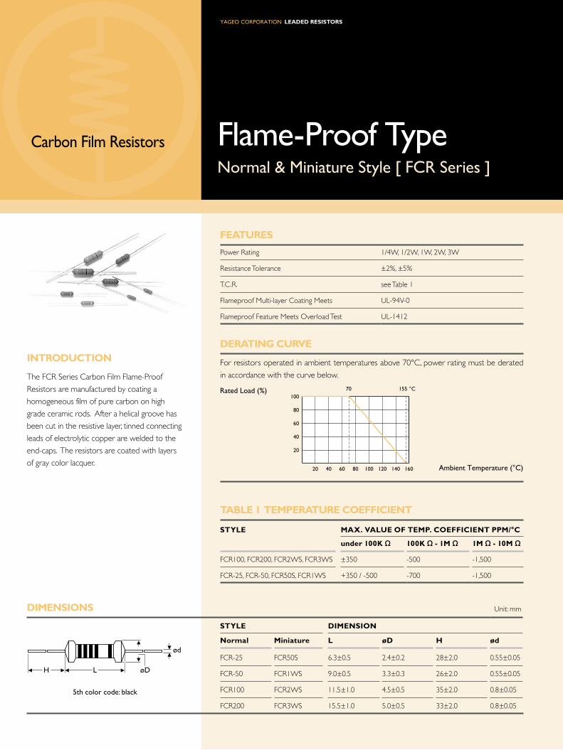
Carbon Film Resistors Flame-Proof TypeNormal & Miniature Style [ FCR Series ]
iNtRodUCtioN
The FCR Series Carbon Film Flame-Proof
Resistors are manufactured by coating a
homogeneous film of pure carbon on high
grade ceramic rods. After a helical groove has
been cut in the resistive layer, tinned connecting
leads of electrolytic copper are welded to the
end-caps. The resistors are coated with layers
of gray color lacquer.
th color code: black
ød
H L øD
Rated Load (%)
Ambient Temperature (°C)160140120100806040
100
80
60
40
20
20
70 155 °C

Note:
3
Note: Rated Continuous Working Voltage (RCWV) = Power Rating x Resistance Value
eLeCtRiCaL CHaRaCteRistiCs
stYLe FCR-25 FCR50s FCR-50 FCR1Ws FCR100 FCR2Ws FCR200 FCR3Ws
Power Rating at 70°C 1/4W 1/2W 1W 2W 3W
Maximum Working Voltage 250V 300V 350V 400V 500V
Maximum Overload Voltage 500V 600V 700V 800V 1,000V
Voltage Proof 400V 500V 600V 750V
Resistance Range 1 Ω - 10M Ω & 0 Ω for E24 series value
Operating Temp. Range -55°C to +155°C
Temperature Coefficient see Table 1
Note: Special value is available on request
eNViRoNMeNtaL CHaRaCteRistiCs
PeRFoRMaNCe test test MetHod aPPRaise
Short Time Overload IEC 60115-1 4.13 2.5 times RCWV for 5 Sec. ±0.75%+0.05 Ω
Voltage Proof IEC 60115-1 4.7 in V-block for 60 Sec., test voltage by type By type
Temperature Coefficient IEC 60115-1 4.8 -55°C to +155°C By type
Insulation Resistance IEC 60115-1 4.6 in V-block for 60 Sec. >1,000M Ω
Solderability IEC 60115-1 4.17 235±5°C for 3±0.5 Sec. 95% Min. coverage
Solvent Resistance of Marking IEC 60115-1 4.30 IPA for 5±0.5 Min. with ultrasonicNo deterioration of
coatings and markings
Robustness of Terminations IEC 60115-1 4.16 Direct load for 10 Sec. in the direction of the terminal leads ≥2.5kg (24.5N)
Periodic-pulse Overload IEC 60115-1 4.39 4 times RCWV 10,000 cycles (1 Sec. on, 25 Sec. off) ±1.0%+0.05 Ω
Damp Heat Steady State IEC 60115-1 4.24 40±2°C, 90-95% RH for 56 days, loaded with 0.1 times RCWV ±3.0%+0.05 Ω
Endurance at 70°C IEC 60115-1 4.25 70±2°C at RCWV for 1,000 Hr. (1.5 Hr. on, 0.5 Hr. off) ±3.0%+0.05 Ω
Temperature Cycling IEC 60115-1 4.19 -55°C Room Temp. +155°C Room Temp. (5 cycles) ±1.0%+0.05 Ω
Resistance to Soldering Heat IEC 60115-1 4.18 260±3°C for 10±1 Sec., immersed to a point 3±0.5mm from the body ±1.0%+0.05 Ω
Accidental Overload Test IEC 60115-1 4.26 4 times RCWV for 1 Min.No evidence of flaming
or arcing
Leaded ResistoRs
diMeNsioNs Unit: mm
stYLe diMeNsioN
Miniature L ød H ød
FC0204 3.4±0.3 1.9±0.2 28±2.0 0.45±0.05
FC0207 6.3±0.5 2.4±0.2 28±2.0 0.55±0.05
FeatURes
Power Rating 0.4W, 0.6W
Resistance Tolerance ±2%, ±5%
T.C.R. see Table 1
Flameproof Multi-layer Coating Meets UL-94V-0
Flameproof Feature Meets Overload Test UL-1412
deRatiNG CURVe
For resistors operated in ambient temperatures above 70°C, power rating must be derated
in accordance with the curve below.
taBLe 1 teMPeRatURe CoeFFiCieNt
stYLe Max. VaLUe oF teMP. CoeFFiCieNt PPM/°C
under 100K Ω 100K Ω - 1M Ω 1M Ω - 10M Ω
FC0204, FC0207 +300 / -500 -700 -1,500
Carbon Film Resistors
Professional & Flame-Proof TypeMiniature Style [ FC0 Series ]
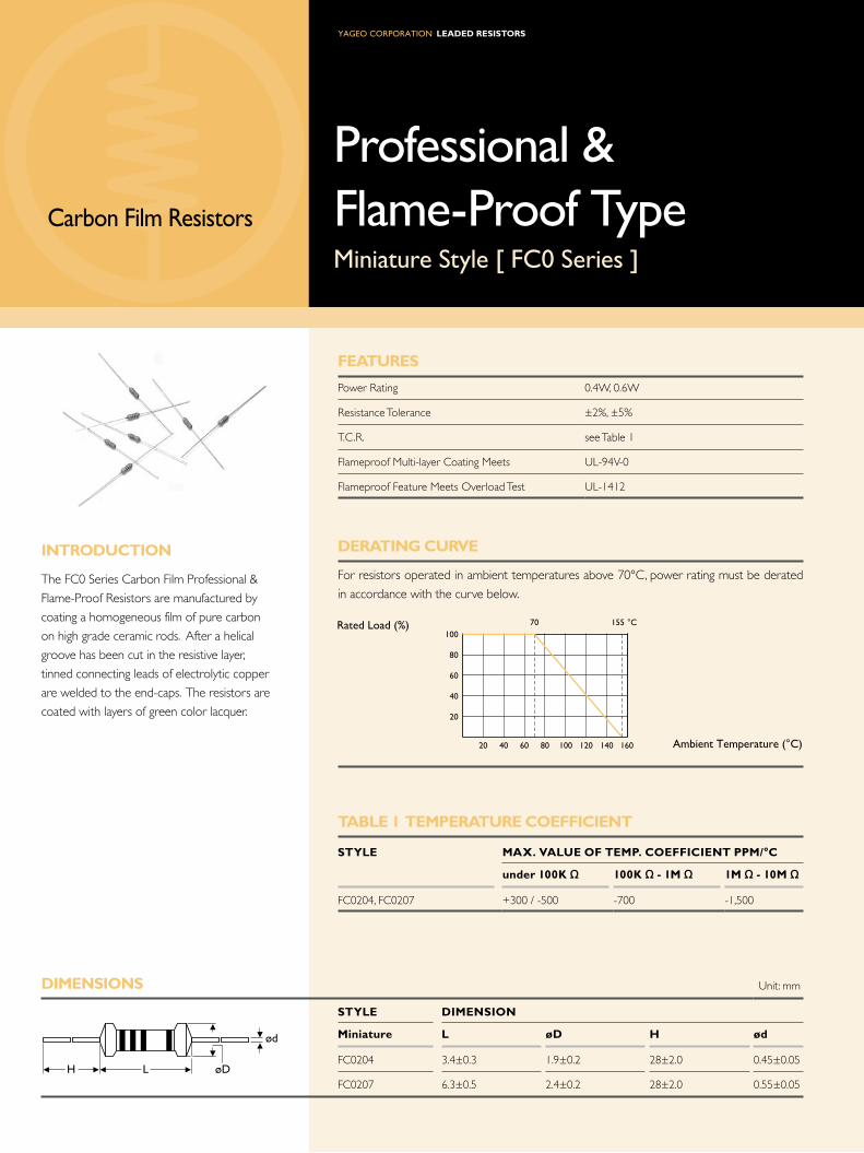
iNtRodUCtioN
The FC0 Series Carbon Film Professional &
Flame-Proof Resistors are manufactured by
coating a homogeneous film of pure carbon
on high grade ceramic rods. After a helical
groove has been cut in the resistive layer,
tinned connecting leads of electrolytic copper
are welded to the end-caps. The resistors are
coated with layers of green color lacquer.
ød
H L øD
Rated Load (%)
Ambient Temperature (°C)160140120100806040
100
80
60
40
20
20
70 155 °C

Note:
3
Note: Rated Continuous Working Voltage (RCWV) = Power Rating x Resistance Value
Professional & Flame-Proof TypeMiniature Style [ FC0 Series ]
eLeCtRiCaL CHaRaCteRistiCs
stYLe FC0204 FC0207
Power Rating at 70°C 0.4W 0.6W
Maximum Working Voltage 200V 300V
Maximum Overload Voltage 400V 600V
Voltage Proof 300V 500V
Resistance Range 1 Ω - 10M Ω & 0 Ω for E24 series value
Operating Temp. Range -55°C to +155°C
Temperature Coefficient see Table 1
Note: Special value is available on request
eNViRoNMeNtaL CHaRaCteRistiCs
PeRFoRMaNCe test test MetHod aPPRaise
Short Time Overload IEC 60115-1 4.13 2.5 times RCWV for 5 Sec. ±0.75%+0.05 Ω
Voltage Proof IEC 60115-1 4.7 in V-block for 60 Sec., test voltage by type By type
Temperature Coefficient IEC 60115-1 4.8 -55°C to +155°C By type
Insulation Resistance IEC 60115-1 4.6 in V-block for 60 Sec. >1,000M Ω
Solderability IEC 60115-1 4.17 235±5°C for 3±0.5 Sec. 95% Min. coverage
Solvent Resistance of Marking IEC 60115-1 4.30 IPA for 5±0.5 Min. with ultrasonicNo deterioration of
coatings and markings
Robustness of Terminations IEC 60115-1 4.16 Direct load for 10 Sec. in the direction of the terminal leads ≥2.5kg (24.5N)
Periodic-pulse Overload IEC 60115-1 4.39 4 times RCWV 10,000 cycles (1 Sec. on, 25 Sec. off) ±1.0%+0.05 Ω
Damp Heat Steady State IEC 60115-1 4.24 40±2°C, 90-95% RH for 56 days, loaded with 0.1 times RCWV ±3.0%+0.05 Ω
Endurance at 70°C IEC 60115-1 4.25 70±2°C at RCWV for 1,000 Hr. (1.5 Hr. on, 0.5 Hr. off) ±3.0%+0.05 Ω
Temperature Cycling IEC 60115-1 4.19 -55°C Room Temp. +155°C Room Temp. (5 cycles) ±1.0%+0.05 Ω
Resistance to Soldering Heat IEC 60115-1 4.18 260±3°C for 10±1 Sec., immersed to a point 3±0.5mm from the body ±1.0%+0.05 Ω
Accidental Overload Test IEC 60115-1 4.26 4 times RCWV for 1 Min.No evidence of flaming
or arcing

Leaded ResistoRs
diMeNsioNs Unit: mm
stYLe diMeNsioN
Normal Miniature L ød H ød
NCR-25 NCR50S 6.3±0.5 2.4±0.2 28±2.0 0.55±0.05
NCR-50 NCR1WS 9.0±0.5 3.3±0.3 26±2.0 0.55±0.05
NCR100 NCR2WS 11.5±1.0 4.5±0.5 35±2.0 0.8±0.05
NCR200 NCR3WS 15.5±1.0 5.0±0.5 33±2.0 0.8±0.05
FeatURes
Power Rating 1/4W, 1/2W, 1W, 2W, 3W
Resistance Tolerance ±5%, ±10%
T.C.R. see Table 1
Flameproof Multi-layer Coating Meets UL-94V-0
Flameproof Feature Meets Overload Test UL-1412
deRatiNG CURVe
For resistors operated in ambient temperatures above 70°C, power rating must be derated
in accordance with the curve below.
taBLe 1 teMPeRatURe CoeFFiCieNt
VaLUe RaNGe Max. VaLUe oF teMP. CoeFFiCieNt PPM/°C
Under 5K Ω -500
5K - 10K Ω -800
Carbon Film Resistors
Non-Inductive & Flame-Proof TypeNormal & Miniature Style [ NCR Series ]
iNtRodUCtioN
The NCR Series Carbon Film Non-Inductive &
Flame-Proof Resistors are manufactured by
coating a homogeneous film of pure carbon
on high grade ceramic rods. Tinned connecting
leads of electrolytic copper are welded to the
end-caps. The inductance is <1μH.
The resistors are coated with layers of gray col-
or lacquer for normal size & pink color lacquer
for miniature size.
th color code: green
ød
H L øD
Rated Load (%)
Ambient Temperature (°C)160140120100806040
100
80
60
40
20
20
70 155 °C

Note:
3
Note: Rated Continuous Working Voltage (RCWV) = Power Rating x Resistance Value
Non-Inductive & Flame-Proof TypeNormal & Miniature Style [ NCR Series ]
eLeCtRiCaL CHaRaCteRistiCs
stYLe NCR-25 NCR50s NCR-50 NCR1Ws NCR100 NCR2Ws NCR200 NCR3Ws
Power Rating at 70°C 1/4W 1/2W 1W 2W 3W
Maximum Working Voltage 250V 300V 350V 400V 500V
Maximum Overload Voltage 500V 600V 700V 800V 1,000V
Voltage Proof 500V 700V 1,000V
Resistance Range 2.2 Ω - 10K Ω for E24 series value
Operating Temp. Range -55°C to +155°C
Temperature Coefficient see Table 1
Note: Special value is available on request
eNViRoNMeNtaL CHaRaCteRistiCs
PeRFoRMaNCe test test MetHod aPPRaise
Short Time Overload IEC 60115-1 4.13 2.5 times RCWV for 5 Sec.±0.75%+0.05 Ω for normal style
±2.0%+0.05 Ω for miniature style
Voltage Proof IEC 60115-1 4.7 in V-block for 60 Sec., test voltage by type By type
Temperature Coefficient IEC 60115-1 4.8 -55°C to +155°C By type
Insulation Resistance IEC 60115-1 4.6 in V-block for 60 Sec. >1,000M Ω
Solderability IEC 60115-1 4.17 235±5°C for 3±0.5 Sec. 95% Min. coverage
Solvent Resistance of Marking IEC 60115-1 4.30 IPA for 5±0.5 Min. with ultrasonicNo deterioration of coatings and
markings
Robustness of Terminations IEC 60115-1 4.16 Direct load for 10 Sec. in the direction of the terminal leads ≥2.5kg (24.5N)
Periodic-pulse Overload IEC 60115-1 4.39 4 times RCWV 10,000 cycles (1 Sec. on, 25 Sec. off) ±1.0%+0.05 Ω
Damp Heat Steady State IEC 60115-1 4.24 40±2°C, 90-95% RH for 56 days, loaded with 0.1 times RCWV ±3.0%+0.05 Ω
Endurance at 70°C IEC 60115-1 4.25 70±2°C at RCWV for 1,000 Hr. (1.5 Hr. on, 0.5 Hr. off) ±3.0%+0.05 Ω
Temperature Cycling IEC 60115-1 4.19 -55°C Room Temp. +155°C Room Temp. (5 cycles) ±1.0%+0.05 Ω
Resistance to Soldering Heat IEC 60115-1 4.18 260±3°C for 10±1 Sec., immersed to a point 3±0.5mm from the
body±1.0%+0.05 Ω
Accidental Overload Test IEC 60115-1 4.26 4 times RCWV for 1 Min. No evidence of flaming or arcing

Leaded ResistoRs
ød
H L øD
Carbon Film Resistors
Rated Load (%)
Ambient Temperature (°C)160140120100806040
100
80
60
40
20
20
70 155 °C
diMeNsioNs Unit: mm
stYLe diMeNsioN
Normal Miniature L ød H ød
CFN-12 CFN25S 3.4±0.3 1.9±0.2 28±2.0 0.45±0.05
CFN-25 CFN50S 6.3±0.5 2.4±0.2 28±2.0 0.55±0.05
CFN-50 CFN1WS 9.0±0.5 3.3±0.3 26±2.0 0.55±0.05
CFN100 CFN2WS 11.5±1.0 4.5±0.5 35±2.0 0.8±0.05
CFN200 CFN3WS 15.5±1.0 5.0±0.5 33±2.0 0.8±0.05
iNtRodUCtioN
The CFN Series Carbon Film Biased Humidity
Resistors are manufactured by coating a
homogeneous film of pure carbon on high
grade ceramic rods. After a helical groove has
been cut in the resistive layer, tinned connecting
leads of electrolytic copper are welded to
the end-caps. The resistors are coated with
a specialized tan lacquer. Its processes and
controls ensure the product is impervious to
moisture.
Biased Humidity TypeNormal & Miniature Style [ CFN Series ]
FeatURes
Power Rating 1/6W, 1/4W, 1/2W, 1W, 2W, 3W
Resistance Tolerance ±2%, ±5%
T.C.R. see Table 1
deRatiNG CURVe
For resistors operated in ambient temperatures above 70°C, power rating must be derated
in accordance with the curve below.
taBLe 1 teMPeRatURe CoeFFiCieNt
stYLe Max. VaLUe oF teMP. CoeFFiCieNt PPM/°C
under 100K Ω 100K Ω - 1M Ω 1M Ω - 10M Ω
CFN100,CFN200,CFN2WS,CFN3WS ±350 -500 -1,500
CFN-12, CFN-25, CFN-50,
CFN25S, CFN50S, CFN1WS+350 / -500 -700 -1,500

Note:
41
Note: Rated Continuous Working Voltage (RCWV) = Power Rating x Resistance Value
eNViRoNMeNtaL CHaRaCteRistiCs
PeRFoRMaNCe test test MetHod aPPRaise
Short Time Overload IEC 60115-1 4.13 2.5 times RCWV for 5 Sec. ±0.75%+0.05 Ω
Voltage Proof IEC 60115-1 4.7 in V-block for 60 Sec., test voltage by typeNo breakdown or
flashover
Temperature Coefficient IEC 60115-1 4.8 -55°C to +155°C By type
Insulation Resistance IEC 60115-1 4.6 in V-block for 60 Sec. >1,000M
Solderability IEC 60115-1 4.17 235±5°C for 3±0.5 Sec. 95% Min. coverage
Solvent Resistance of Marking IEC 60115-1 4.30 IPA for 5±0.5 Min. with ultrasonic No deterioration of
coatings and markings
Robustness of Terminations IEC 60115-1 4.16 Direct load for 10 Sec. in the direction of the terminal leads ≥2.5kg (24.5N)
Periodic-pulse Overload IEC 60115-1 4.39 4 times RCWV 10,000 cycles (1 Sec. on, 25 Sec. off) ±1.0%+0.05 Ω
Damp Heat Steady State IEC 60115-1 4.24 40±2°C, 90-95% RH for 56 days, loaded with 0.1 times RCWV ±3%+0.05 Ω
Endurance at 70°C IEC 60115-1 4.25 70±2°C at RCWV for 1,000 Hr. (1.5 Hr. on, 0.5 Hr. off) ±3%+0.05 Ω
Temperature Cycling IEC 60115-1 4.19 -55°C Room Temp. +155°C Room Temp. (5 cycles) ±1%+0.05 Ω
Resistance to Soldering Heat IEC 60115-1 4.18 260±3°C for 10±1 Sec., immersed to a point 3±0.5mm from the body ±1%+0.05 Ω
eLeCtRiCaL CHaRaCteRistiCs
stYLe CFN-12 CFN25s CFN-25 CFN50s CFN-50 CFN1Ws CFN100 CFN2Ws CFN200 CFN3Ws
Power Rating at 70°C 1/6W 1/4W 1/2W 1W 2W 3W
Maximum Working Voltage 150V 200V 250V 300V 350V 400V 500V
Maximum Overload Voltage 300V 400V 500V 600V 700V 800V 1,000V
Voltage Proof 300V 400V 500V 700V 1,000V
Resistance Range 1 Ω - 10M Ω & 0 Ω for E24 series value
Operating Temp. Range -55°C to +155°C
Temperature Coefficient see Table 1
Note: Special value is available on request

Leaded ResistoRs
diMeNsioNs Unit: mm
stYLe diMeNsioN
Normal Miniature L d C Min.
MCF-12 MCF25S / MCF204 3.50±0.2 1.40±0.15 0.5
MCF-25 MCF50S / MCF207 5.90±0.2 2.20±0.1 0.5
MCF-50 MCF1WS 8.50±0.2 3.20±0.2 0.5
FeatURes
Power Rating 1/6W, 1/4W, 0.4W, 1/2W, 0.6W, 1W
Resistance Tolerance ±2%, ±5%
T.C.R. see Table 1
deRatiNG CURVe
For resistors operated in ambient temperatures above 70°C, power rating must be derated
in accordance with the curve below.
taBLe 1 teMPeRatURe CoeFFiCieNt
stYLe Max. VaLUe oF teMP. CoeFFiCieNt PPM/°C
MCF-12, MCF25S, MCF204 under 1K Ω 1K1 Ω -47K Ω 51K Ω -470K Ω 510K Ω -1M Ω
0 to -350 0 to -600 0 to -1,000 0 to -1,500
MCF-25, MCF50S, MCF207, under 10K Ω 11K Ω -150KΩ 160K Ω -2M2 Ω
MCF-50, MCF1WS 0 to -350 0 to -600 0 to -1,000
General TypeNormal & Miniature Style [ MCF Series ]
Melf Carbon Film Resistors
iNtRodUCtioN
The MCF Series Melf Carbon Film Resistors
are manufactured by coating a homogeneous
film of pure carbon on high grade ceramic
rods. After a helical groove has been cut in
the resistive layer, tinned connecting leads of
electrolytic copper are welded to the end-caps.
SMD enabled structure. The resistors are
coated with layers of lacquer.
LC
D
Rated Load (%)
Ambient Temperature (°C)160140120100806040
100
80
60
40
20
20
70 155 °C

Note:
43
Note: Rated Continuous Working Voltage (RCWV) = Power Rating x Resistance Value
eLeCtRiCaL CHaRaCteRistiCs
stYLe MCF-12 MCF25s MCF204 MCF-25 MCF50s MCF207 MCF-50 MCF1Ws
Power Rating at 70°C 1/6W 1/4W 0.4W 1/4W 1/2W 0.6W 1/2W 1W
Maximum Working Voltage 200V 250V 300V 350V
Maximum Overload Voltage 400V 500V 600V 700V
Voltage Proof 200V 500V 700V
Resistance Range 10 Ω - 1M Ω & 0 Ω for E24 series value
Operating Temp. Range -55°C to +155°C
Temperature Coefficient see Table 1
Note: Special value is available on request
eNViRoNMeNtaL CHaRaCteRistiCs
PeRFoRMaNCe test test MetHod aPPRaise
Short Time Overload IEC 60115-1 4.13 2.5 times RCWV for 5 Sec. ±1.0%+0.05 Ω
Voltage Proof IEC 60115-1 4.7 in V-block for 60 Sec., test voltage by type By type
Temperature Coefficient IEC 60115-1 4.8 -55°C to +155°C By type
Insulation Resistance IEC 60115-1 4.6 in V-block for 60 Sec. >10,000M Ω
Solderability IEC 60115-1 4.17 235±5°C for 3±0.5 Sec. 95% Min. coverage
Solvent Resistance of Marking IEC 60115-1 4.30 IPA for 5±0.5 Min. with ultrasonicNo deterioration of
coatings and markings
Periodic-pulse Overload IEC 60115-1 4.39 4 times RCWV 10,000 cycles (1 Sec. on, 25 Sec. off) ±1.0%+0.05 Ω
Damp Heat Steady State IEC 60115-1 4.24 40±2°C, 90-95% RH for 56 days, loaded with 0.1 times RCWV ±5.0%+0.1 Ω
Endurance at 70°C IEC 60115-1 4.25 70±2°C at RCWV for 1,000 Hr. (1.5 Hr. on, 0.5 Hr. off) ±3.0%+0.1 Ω
Temperature Cycling IEC 60115-1 4.19 -55°C Room Temp. +155°C Room Temp. (5 cycles) ±0.75%+0.05 Ω
Resistance to Soldering Heat IEC 60115-1 4.18 260±3°C for 10±1 Sec., immersed to a point 3±0.5mm from the body ±1.0%+0.05 Ω

Leaded ResistoRs
diMeNsioNs Unit: mm
stYLe diMeNsioN
Ultra Miniature L d C Min.
MCP100 5.9±0.2 2.2±0.1 0.5
MCP200 8.5±0.2 3.2±0.2 0.5
FeatURes
Power Rating 1W, 2W
Resistance Tolerance ±2%, ±5%
T.C.R. see Table 1
deRatiNG CURVe
For resistors operated in ambient temperatures above 70°C, power rating must be derated
in accordance with the curve below.
taBLe 1 teMPeRatURe CoeFFiCieNt
stYLe Max. VaLUe oF teMP. CoeFFiCieNt PPM/°C
under 10K Ω 11K Ω -150K Ω 160K Ω -2M2 Ω
MCP100, MCP200 0 to -350 0 to -600 0 to -1,000
High Power TypeUltra Miniature Style [ MCP Series ]
Melf Carbon Film Resistors
iNtRodUCtioN
The MCP Series Melf Carbon Film High
Power Resistors are manufactured by coating
a homogeneous film of pure carbon on high
grade ceramic rods. After a helical groove has
been cut in the resistive layer, tinned connecting
leads of electrolytic copper are welded to the
end-caps. SMD enabled structure and high
power in small packages. The resistors are
coated with layers of lacquer.
LC
D
Rated Load (%)
Ambient Temperature (°C)160140120100806040
100
80
60
40
20
20
70 155 °C

Note:
4
Note: Rated Continuous Working Voltage (RCWV) = Power Rating x Resistance Value
eLeCtRiCaL CHaRaCteRistiCs
stYLe MCP100 MCP200
Power Rating at 70°C 1W 2W
Maximum Working Voltage 350V
Maximum Overload Voltage 700V
Voltage Proof 500V
Resistance Range 1 Ω - 1M Ω & 0 Ω for E24 & E96 series value
Operating Temp. Range -55°C to +155°C
Temperature Coefficient See Table 1
Note: Special value is available on request
eNViRoNMeNtaL CHaRaCteRistiCs
PeRFoRMaNCe test test MetHod aPPRaise
Short Time Overload IEC 60115-1 4.13 2.5 times RCWV for 5 Sec. ±1.0%+0.05 Ω
Voltage Proof IEC 60115-1 4.7 in V-block for 60 Sec., test voltage by type By type
Temperature Coefficient IEC 60115-1 4.8 -55°C to +155°C By type
Insulation Resistance IEC 60115-1 4.6 in V-block for 60 Sec. >10,000M Ω
Solderability IEC 60115-1 4.17 235±5°C for 3±0.5 Sec. 95% Min. coverage
Solvent Resistance of Marking IEC 60115-1 4.30 IPA for 5±0.5 Min. with ultrasonicNo deterioration of
coatings and markings
Periodic-pulse Overload IEC 60115-1 4.39 4 times RCWV 10,000 cycles (1 Sec. on, 25 Sec. off) ±1.0%+0.05 Ω
Damp Heat Steady State IEC 60115-1 4.24 40±2°C, 90-95% RH for 56 days, loaded with 0.1 times RCWV ±5.0%+0.1 Ω
Endurance at 70°C IEC 60115-1 4.25 70±2°C at RCWV for 1,000 Hr. (1.5 Hr. on, 0.5 Hr. off) ±3.0%+0.1 Ω
Temperature Cycling IEC 60115-1 4.19 -55°C Room Temp. +155°C Room Temp. (5 cycles) ±0.75%+0.05 Ω
Resistance to Soldering Heat IEC 60115-1 4.18 260±3°C for 10±1 Sec., immersed to a point 3±0.5mm from the body ±1.0%+0.05 Ω

Leaded ResistoRs
FeatURes
Power Rating 1/4W, 1/2W, 1W, 2W, 3W
Resistance Tolerance ±1%, ±5%
T.C.R. ±200ppm/°C
Flameproof Multi-layer Coating Meets UL-94V-0
Flameproof Feature Meets Overload Test UL-1412
deRatiNG CURVe
For resistors operated in ambient temperatures above 70°C, power rating must be derated
in accordance with the curve below.
Metal Glazed Film Resistors
iNtRodUCtioN
The HHV Series High Voltage & High Ohmic
Resistors are made of metal glaze film, with
tinned connecting leads of electrolytic copper
welded to the end of caps. The resistors are
coated with layers of pink color lacquer.
High Voltage & High Ohmic TypeNormal & Miniature Style [ HHV Series ]
th color code: yellow
ød
H L øD
Rated Load (%)
Ambient Temperature (°C)160140120100806040
100
80
60
40
20
20
70 155 °C
diMeNsioNs Unit: mm
stYLe diMeNsioN
Normal Miniature L ød H ød
HHV-25 HHV50S 6.3±0.5 2.4±0.2 28±2.0 0.55±0.05
HHV-50 HHV1SS 9.0±0.5 3.3±0.3 26±2.0 0.55±0.05
HHV1WS HHV2SS 11.5±1.0 4.5±0.5 35±2.0 0.8±0.05
HHV2WS HHV3SS 15.5±1.0 5.0±0.5 33±2.0 0.8±0.05

Note:
4
Note: Rated Continuous Working Voltage (RCWV) = Power Rating x Resistance Value
eLeCtRiCaL CHaRaCteRistiCs
stYLe HHV-25 HHV50s HHV-50 HHV1ss HHV1Ws HHV2ss HHV2Ws HHV3ss
Power Rating at 70°C 1/4W 1/2W 1W 2W 3W
Maximum Working Voltage (DC) 1,600V 3,500V 5,000V 7,000V
Maximum Overload Voltage (DC) 3,000V 7,000V 10,000V 14,000V
Voltage Proof 300V 500V 600V
Resistance Range 100K Ω - 68M Ω for E24 & E96 series value
Operating Temp. Range -55°C to +155°C
Temperature Coefficient ±200pm/°C
Note: Special value is available on request
eNViRoNMeNtaL CHaRaCteRistiCs
PeRFoRMaNCe test test MetHod aPPRaise
Short Time Overload IEC 60115-1 4.13 2.5 times RCWV for 5 Sec. ±2.0%+0.05 Ω
Voltage Proof IEC 60115-1 4.7 in V-block for 60 Sec., test voltage by type By type
Temperature Coefficient IEC 60115-1 4.8 -55°C to +155°C By type
Insulation Resistance IEC 60115-1 4.6 in V-block for 60 Sec. >10,000M Ω
Solderability IEC 60115-1 4.17 235±5°C for 3±0.5 Sec. 95% Min. coverage
Solvent Resistance of Marking IEC 60115-1 4.30 IPA for 5±0.5 Min. with ultrasonic No deterioration of
coatings and markings
Robustness of Terminations IEC 60115-1 4.16 Direct load for 10 Sec. in the direction of the terminal leads ≥2.5kg (24.5N)
Periodic-pulse Overload IEC 60115-1 4.39 4 times RCWV 10,000 cycles (1 Sec. on, 25 Sec. off) ±1.0%+0.05 Ω
Damp Heat Steady State IEC 60115-1 4.24 40±2°C, 90-95% RH for 56 days, loaded with 0.1 times RCWV ±5.0%+0.05 Ω
Endurance at 70°C IEC 60115-1 4.25 70±2°C at RCWV for 1,000 Hr. (1.5 Hr. on, 0.5 Hr. off) ±5.0%+0.05 Ω
Temperature Cycling IEC 60115-1 4.19 -55°C Room Temp. +155°C Room Temp. (5 cycles) ±1.0%+0.05 Ω
Resistance to Soldering Heat IEC 60115-1 4.18 260±3°C for 10±1 Sec., immersed to a point 3±0.5mm from the body ±1.0%+0.05 Ω
Accidental Overload Test IEC 60115-1 4.26 4 times RCWV for 1 Min.No evidence of flaming
or arcing

Leaded ResistoRs
Pulse-Loading Resistors
iNtRodUCtioN
The APR Series Pulse-Loading Resistors have
excellent capability in withstanding pulse; tinned
connecting leads of electrolytic copper are
welded to the end-caps. The resistors are
coated with layers of gray color lacquer. The
5th color band is yellow to represent APR
series.
FeatURes
Power Rating 1/4W, 1/2W, 1W, 2W, 3W
Resistance Tolerance 5%
T.C.R. ±300ppm/°C
Flameproof Multi-layer Coating Meets UL-94V-0
Flameproof Feature Meets Overload Test UL-1412
deRatiNG CURVe
For resistors operated in ambient temperatures above 70°C, power rating must be derated
in accordance with the curve below.
Rated Load (%)
Ambient Temperature (°C)160 180 200140120100806040
100
80
60
40
20
20
70 200°C
ød
H L øD
diMeNsioNs Unit: mm
stYLe diMeNsioN
Normal Minuature L ød H ød
APR-25 APR50S 6.3±0.5 2.4±0.2 28±2.0 0.55±0.05
APR-50 APR1WS 9.0±0.5 3.3±0.3 26±2.0 0.55±0.05
APR100 APR2WS 11.5±1.0 4.5±0.5 35±2.0 0.80±0.05
APR200 APR3WS 15.5±1.0 5.0±0.5 33±2.0 0.80±0.05
5th color code: yellow
Anti-Pulse TypeNormal & Miniature Style [ APR Series ]

Note:
4
Note: Rated Continuous Working Voltage (RCWV) = Power Rating x Resistance Value
eLeCtRiCaL CHaRaCteRistiCs
stYLe aPR-25 aPR50s aPR-50 aPR1Ws aPR100 aPR2Ws aPR200 aPR3Ws
Power Rating at 70°C 1/4W 1/2W 1W 2W 3W
Maximum Working Voltage 250V 350V 400V 500V
Maximum Overload Voltage 500V 600V 700V 800V 1,000V
Voltage Proof 400V 500V 600V 750V
Resistance Range 1 Ω - 100K Ω & 0 Ω for E24 series value
Operating Temp. Range -55°C to +200°C
Temperature Coefficient ±300ppm/°C
Note: Special value is available on request
eNViRoNMeNtaL CHaRaCteRistiCs
PeRFoRMaNCe test test MetHod aPPRaise
Short Time Overload IEC 60115-1 4.13 2.5 times RCWV for 5 Sec. ±0.75%+0.05 Ω
Voltage Proof IEC 60115-1 4.7 in V-block for 60 Sec., test voltage by type By type
Temperature Coefficient IEC 60115-1 4.8 -55°C to +155°C By type
Insulation Resistance IEC 60115-1 4.6 in V-block for 60 Sec. >10,000M
Solderability IEC 60115-1 4.17 235±5°C for 3±0.5 Sec. 95% Min. coverage
Solvent Resistance of Marking IEC 60115-1 4.30 IPA for 5±0.5 Min. with ultrasonicNo deterioration of
coatings and markings
Robustness of Terminations IEC 60115-1 4.16 Direct load for 10 Sec. in the direction of the terminal leads ≥2.5kg (24.5N)
Periodic-pulse Overload IEC 60115-1 4.39 4 times RCWV 10,000 cycles (1 Sec. on, 25 Sec. off) ±1.0%+0.05 Ω
Damp Heat Steady State IEC 60115-1 4.24 40±2°C, 90-95% RH for 56 days, loaded with 0.1 times RCWV ±3.0%+0.05 Ω
Endurance at 70°C IEC 60115-1 4.25 70±2°C at RCWV for 1,000 Hr. (1.5 Hr. on, 0.5 Hr. off) ±3.0%+0.05 Ω
Temperature Cycling IEC 60115-1 4.19 -55°C Room Temp. +155°C Room Temp. (5 cycles) ±1.0%+0.05 Ω
Resistance to Soldering Heat IEC 60115-1 4.18 260±3°C for 10±1 Sec., immersed to a point 3±0.5mm from the body ±1.0%+0.05 Ω
Accidental Overload Test IEC 60115-1 4.26 4 times RCWV for 1 Min.No evidence of flaming
or arcing

Leaded ResistoRs
diMeNsioNs Unit: mm
stYLe diMeNsioN
Normal L ød H ød
ZOR-12 3.3±0.4 1.8±0.3 28±2.0 0.45±0.05
ZOR-25 6.3±0.5 2.3±0.3 28±2.0 0.55±0.05
Zero Ohm Resistors Coating TypeNormal Style [ ZOR Series ]
iNtRodUCtioN
• Similar to a 1/4W resistor (1/6W size also
available)
• Ideal for automatic insertion or Cut and Form
• Available in Tape/Reel, Tape/Box and Bulk
• Products meet EU-RoHS requirements
Single color code: black
ød
H L øD
sPeCiFiCatioNs
Power Rating 1/6W, 1/4W
Maximum Resistance 20m Ω or less
Dry 10,000M ΩMin. Insulation Resistance
Wet 100M Ω
Atmospheric 500V RMSMin. Dielectric Withstanding Voltage
Reduced 325V RMS
Insulation FlammabilityResistor insulation is self extinguishing within 10
Sec. after externally applied flame is removed
2.5 AMPS at 70°C for 1/4WCurrent Rating
1.5 AMPS at 70°C for 1/6W
deRatiNG CURVe
For resistors operated in ambient temperatures above 70°C, power rating must be derated
in accordance with the curve below.
Rated Load (%)
Ambient Temperature (°C)160140120100806040
100
80
60
40
20
20
70 155 °C

diMeNsioNs Unit: mm
stYLe diMeNsioN
Normal ød L s a
JPW-05 0.5±0.05
JPW-06 0.6±0.05 26.0±1.0
JPW-07 0.7±0.05 52.4±1.0 5.0±0.1 6.0±0.5
JPW-08 0.8±0.05 73.0±1.5
JPW-10 1.0±0.05
iNtRodUCtioN
Jumper wires or crossovers, as they are sometimes called, are basically interconnection devices between points on a PC Board. Generally they are used for the following reasons:
• Inability to connect two points on a PC Board
due to other circuit paths which must be
crossed over
• An After-the-Fact design change that requires
new point connections
• Circuit tuning by changing point connections
Jumper wires offers a quick simple solution to these problems. They are especially suited for automatic machine insertion on lead tape , and are available in all packaging styles, including pre-cut and formed leads, for manual insertion.
• Products meet EU-RoHS requirements
ød
P & H dimensionon request ød
H
P
S
aL
sPeCiFiCatioNs
Material of Jumper Wire Soft copper wire with tin plating
Wire Diameter ø0.5, ø0.6, ø0.7, ø0.8, ø1.0 (±0.05mm)
Tension Strength CNS 8938 within 28kg/mm²
CNS 8938 ø0.5 to ø0.6mm over 24%Extension Rate
CNS 8938 ø0.7 to ø1.0mm over 26%
ø0.5mm Minmum 94%Conductivity
ø0.6 to ø1.0mm Minmum 96%
CNS 8938 ø0.5mm Load 250g 3 cycles
Twisting Strength CNS 8938 ø0.6 to ø0.8mm Load 500g 3 cycles
CNS 8938 ø1.0mm Load 1.0kg 3 cycles
Solderability 235±5°C, 3±0.5 Sec. coverage 95%
Element of Plating Tin Minimum 99.9%
Thickness of Plating 4±1μm
ø0.5mm 6 AMPS at 70°C
ø0.6mm 7.5 AMPS at 70°C
Current Rating ø0.7mm 8.5 AMPS at 70°C
ø0.8mm 10 AMPS at 70°C
ø1.0mm 15 AMPS at 70°C
Appearance Smooth and shining
Tinned-Copper Wire Type
Normal Style [ JPW Series ]
Jumper Wires

Leaded ResistoRs
FeatURes
Material Manganese-copper, Nickel-copper, others upon request
Resistance Tolerance ±2%, ±5%
T.C.R. ±50ppm/°C, ±100ppm/°C, ±200ppm/°C
Low Ohmic Wire Resistors
diMeNsioNs Unit: mm
stYLe diMeNsioN
Normal ød C H P, L
MCW-06 0.6±0.02 0.9±0.1 3.0±0.5
P & L could be
designed by customer's
requirement
MCW-08 0.8±0.02 1.1±0.1 3.0±0.5
MCW-10 1.0±0.02 1.3±0.1 3.0±0.5
MCW-12 1.2±0.02 1.5±0.1 3.0±0.5
MCW-14 1.4±0.02 1.7±0.1 3.0±0.5
MCW-16 1.6±0.02 1.9±0.2 3.0±0.5
MCW-18 1.8±0.02 2.2±0.2 3.0±0.5
MCW-20 2.0±0.02 2.5±0.2 3.0±0.5
MCW-26 2.6±0.02 3.2±0.2 3.0±0.5
Alloy-Wire TypeNormal Style [ MCW Series ]
iNtRodUCtioN
• The Low Ohmic Alloy-Wire Resistors are
suitable for high power current detection, it is
non-inductive type
• Low Ohmic Wire Resistors meet EU-RoHS
requirements
P
øDMax 0.5
P
øD
C
P
øDC
Max 0.5
Max 0.5
M-Type
W-Type
K-Type
B-Type
N-Type
Max 0.5
L L
H
L
H
L
H
L
H
Max 0.5
øDC
p
pøDC

Note:
3
Note: Rated Continuous Working Voltage (RCWV) = Power Rating x Resistance Value
eNViRoNMeNtaL CHaRaCteRistiCs
PeRFoRMaNCe test test MetHod aPPRaise
Short Time Overload IEC 60115-1 4.13 2.5 times RCWV for 5 Sec. ±2%
Temperature Coefficient IEC 60115-1 4.8 -55°C to +125°C By type
Solderability IEC 60115-1 4.17 235±5°C for 3±0.5 Sec. 95% Min. coverage
Damp Heat Steady State IEC 60115-1 4.24 40±2°C, 90-95% RH for 56 days, loaded with 0.1 times RCWV ±2.0%
Endurance at 70°C IEC 60115-1 4.25 70±2°C at RCWV for 1,000 Hr. (1.5 Hr. on, 0.5 Hr. off) ±3.0%
Temperature Cycling IEC 60115-1 4.19 -55°C Room Temp. +155°C Room Temp. (5 cycles) ±1.0%
Resistance to Soldering Heat IEC 60115-1 4.18 260±3°C for 10±1 Sec., immersed to a point 3±0.5mm from the body ±1.0%
eLeCtRiCaL CHaRaCteRistiCs
stYLe MCW-06 MCW-08 MCW-10 MCW-12 MCW-14 MCW-16 MCW-18 MCW-20 MCW-26
Maximum Current Rating 3A 4.5A 5.5A 7.0A 8.0A 9.5A 11A 12A 18A
Resistance Range 0.0014 Ω - 0.078 Ω
Operating Temp. Range -55°C to +125°C
Temperature Coefficient ±50ppm/°C, ±100ppm/°C, ±200ppm/°C
Note: Below or over this resistance value is available on request

Leaded ResistoRs
diMeNsioNs Unit: mm
stYLe diMeNsioN
Normal Miniature L ød H ød
KNP-25 NP50S 6.3±0.5 2.4±0.2 28±2.0 0.55±0.05
KNP-50 KNP1WS 9.0±0.5 3.3±0.3 26±2.0 0.55±0.05
KNP100 KNP2WS 11.5±1.0 4.5±0.5 35±2.0 0.8±0.05
KNP200 KNP3WS 15.5±1.0 5.0±0.5 33±2.0 0.8±0.05
KNP300KNP5WS 17.5±1.0 6.5±0.5 32±2.0 0.8±0.05
KNP400
KNP500 KNP7WS 24.5±1.0 8.0±0.5 38±2.0 0.8±0.05
KNP700 - 24.5±1.0 8.0±0.5 38±2.0 0.8±0.05
Note: KNP1WS ( for MB Type ) ød = 0.8±0.05 mm
FeatURes
Power Rating 1/4W, 1/2W, 1W, 2W, 3W, 4W, 5W, 7W
Resistance Tolerance ±1%, ±5%
T.C.R. ±300ppm/°C
Flameproof Multi-layer Coating Meets UL-94V-0
Flameproof Feature Meets Overload Test UL-1412
deRatiNG CURVe
For resistors operated in ambient temperatures above 40°C, power rating must be derated
in accordance with the curve below.
ød
H L øD
iNtRodUCtioN
The resistor element is a resistive wire which is
wound in a single layer on a ceramic rod, with
tinned connecting wires of electrolytic copper
welded to the end-caps. The ends of the
resistive wire and the leads are connected to
the caps by welding. The resistors are coated
with layers of green color flame-proof lacquer.
Wirewound Resistors Flame-Proof TypeNormal & Miniature Style [ KNP Series ]
Rated Load (%)
Ambient Temperature (°C)30025020015010050
100
80
60
40
20
70
3W-7W
1/4W-3WS
200 27540 °C

Note: Rated Continuous Working Voltage (RCWV) = Power Rating x Resistance Value
eLeCtRiCaL CHaRaCteRistiCs
NoRMaL stYLe
stYLe KNP-25 KNP-50 KNP100 KNP200 KNP300 KNP400 KNP500 KNP700
Power Rating at 40°C 3W 4W 5W 7W
Power Rating at 70°C 1/4W 1/2W 1W 2W
Voltage Proof 250V 300V 400V
Resistance Range (±1%) 0.22 Ω - 150 Ω 0.1 Ω - 800 Ω 0.1 Ω - 1.8K Ω 0.1 Ω - 2.8K Ω 0.1 Ω - 7.5K Ω 0.1 Ω - 6.5K Ω
Resistance Range (±5%) 0.05 Ω - 200 Ω 0.03 Ω - 800 Ω 0.015 Ω - 2.2K Ω 0.015 Ω - 2.8K Ω 0.02 Ω - 7.5K Ω 0.03 Ω - 6.8K Ω
Operating Temp. Range -40°C to +200°C
Temperature Coefficient ±300ppm/°C
Note: Special value is available on request
MiNiatURe stYLe
stYLe KNP50s KNP1Ws KNP2Ws KNP3Ws KNP5Ws KNP7Ws
Power Rating at 40°C 5W 7W
Power Rating at 70°C 1/2W 1W 2W 3W
Voltage Proof 200V 300V 400V
Resistance Range (±1%) 0.22 Ω - 150 Ω 0.1 Ω - 800 Ω 0.1 Ω - 1.8K Ω 0.1 Ω - 2.8K Ω 0.1 Ω - 7.5K Ω 0.1 Ω - 6.5K Ω
Resistance Range (±5%) 0.05 Ω - 200 Ω 0.03 Ω - 800 Ω 0.015 Ω - 2.2K Ω 0.015 Ω - 2.8K Ω 0.02 Ω - 7.5K Ω 0.03 Ω - 6.8K Ω
Operating Temp. Range -40°C to +200°C
Temperature Coefficient ±300ppm/°C
Note: Special value is available on request
eNViRoNMeNtaL CHaRaCteRistiCs
PeRFoRMaNCe test test MetHod aPPRaise
Short Time Overload IEC 60115-1 4.13 10 times rated power for 5 Sec. ±2.0%+0.05 Ω
Voltage Proof IEC 60115-1 4.7 in V-block for 60 Sec., test voltage by type By type
Temperature Coefficient IEC 60115-1 4.8 -55°C to +155°C By type
Insulation Resistance IEC 60115-1 4.6 in V-block for 60 Sec. >100M Ω
Solderability IEC 60115-1 4.17 235±5°C for 3±0.5 Sec 95% Min. coverage
Solvent Resistance of Marking IEC 60115-1 4.30 IPA for 5±0.5 Min. with ultrasonicNo deterioration of
coatings and markings
Robustness of Terminations IEC 60115-1 4.16 Direct load for 10 Sec. in the direction of the terminal leads ≥2.5kg (24.5N)
Damp Heat Steady State IEC 60115-1 4.24 40±2°C, 90-95% RH for 56 days, loaded with 0.1 times RCWV ±5.0%+0.05 Ω
Endurance at 70°C IEC 60115-1 4.25 70±2°C at RCWV for 1,000 Hr. (1.5 Hr. on, 0.5 Hr. off) ±5.0%+0.05 Ω
Temperature Cycling IEC 60115-1 4.19 -55°C Room Temp. +155°C Room Temp. (5 cycles) ±1.0%+0.05 Ω
Resistance to Soldering Heat IEC 60115-1 4.18 260±3°C for 10±1 Sec., immersed to a point 3±0.5mm from the body ±1.0%+0.05 Ω
Accidental Overload Test IEC 60115-1 4.26 4 times RCWV for 1 Min.No evidence of flaming
or arcing
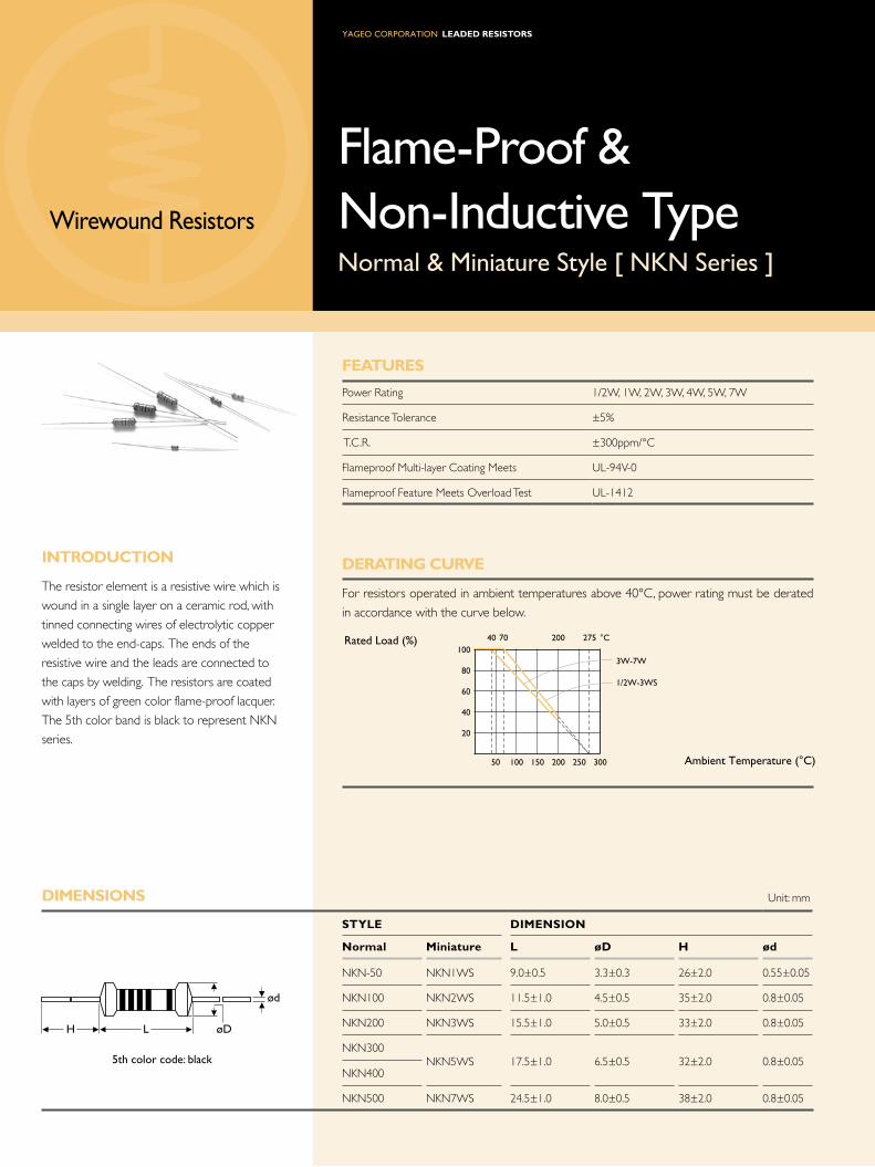
Leaded ResistoRs
FeatURes
Power Rating 1/2W, 1W, 2W, 3W, 4W, 5W, 7W
Resistance Tolerance ±5%
T.C.R. ±300ppm/°C
Flameproof Multi-layer Coating Meets UL-94V-0
Flameproof Feature Meets Overload Test UL-1412
deRatiNG CURVe
For resistors operated in ambient temperatures above 40°C, power rating must be derated
in accordance with the curve below.
diMeNsioNs Unit: mm
stYLe diMeNsioN
Normal Miniature L ød H ød
NKN-50 NKN1WS 9.0±0.5 3.3±0.3 26±2.0 0.55±0.05
NKN100 NKN2WS 11.5±1.0 4.5±0.5 35±2.0 0.8±0.05
NKN200 NKN3WS 15.5±1.0 5.0±0.5 33±2.0 0.8±0.05
NKN300
NKN400NKN5WS 17.5±1.0 6.5±0.5 32±2.0 0.8±0.05
NKN500 NKN7WS 24.5±1.0 8.0±0.5 38±2.0 0.8±0.05
Flame-Proof & Non-Inductive TypeNormal & Miniature Style [ NKN Series ]
iNtRodUCtioN
The resistor element is a resistive wire which is
wound in a single layer on a ceramic rod, with
tinned connecting wires of electrolytic copper
welded to the end-caps. The ends of the
resistive wire and the leads are connected to
the caps by welding. The resistors are coated
with layers of green color flame-proof lacquer.
The 5th color band is black to represent NKN
series.
th color code: black
ød
H L øD
Rated Load (%)
Ambient Temperature (°C)30025020015010050
100
80
60
40
20
70
3W-7W
1/2W-3WS
200 27540 °C
Wirewound Resistors

Note: Rated Continuous Working Voltage (RCWV) = Power Rating x Resistance Value
eLeCtRiCaL CHaRaCteRistiCs
NoRMaL stYLe
stYLe NKN-50 NKN100 NKN200 NKN300 NKN400 NKN500
Power Rating at 40°C 3W 4W 5W
Power Rating at 70°C 1/2W 1W 2W
Voltage Proof 250V 400V
Resistance Range 0.08 Ω - 15 Ω 0.05 Ω - 40 Ω 0.03 Ω - 90 Ω 0.1 Ω - 120 Ω 0.18 Ω - 220 Ω
Operating Temp. Range -40°C to +200°C
Temperature Coefficient ±300ppm/°C
Note: Special value is available on request
MiNiatURe stYLe
stYLe NKN1Ws NKN2Ws NKN3Ws NKN5Ws NKN7Ws
Power Rating at 40°C 5W 7W
Power Rating at 70°C 1W 2W 3W
Voltage Proof 250V 400V
Resistance Range 0.08 Ω - 15 Ω 0.05 Ω - 40 Ω 0.03 Ω - 90 Ω 0.1 Ω - 120 Ω 0.18 Ω - 220 Ω
Operating Temp. Range - 40°C to +200°C
Temperature Coefficient ±300ppm/°C
Note: Special value is available on request
eNViRoNMeNtaL CHaRaCteRistiCs
PeRFoRMaNCe test test MetHod aPPRaise
Short Time Overload IEC 60115-1 4.13 10 times rated power for 5 Sec. ±2.0%+0.05 Ω
Voltage Proof IEC 60115-1 4.7 in V-block for 60 Sec., test voltage by type By type
Temperature Coefficient IEC 60115-1 4.8 -55°C to +155°C By type
Insulation Resistance IEC 60115-1 4.6 in V-block for 60 Sec. >100M Ω
Solderability IEC 60115-1 4.17 235±5°C for 3±0.5 Sec. 95% Min. coverage
Solvent Resistance of Marking IEC 60115-1 4.30 IPA for 5±0.5 Min. with ultrasonic No deterioration of
coatings and markings
Robustness of Terminations IEC 60115-1 4.16 Direct load for 10 Sec. in the direction of the terminal leads ≥2.5kg (24.5N)
Damp Heat Steady State IEC 60115-1 4.24 40±2°C, 90-95% RH for 56 days, loaded with 0.1 times RCWV ±5.0%+0.05 Ω
Endurance at 70°C IEC 60115-1 4.25 70±2°C at RCWV for 1,000 Hr. (1.5 Hr. on, 0.5 Hr. off) ±5.0%+0.05 Ω
Temperature Cycling IEC 60115-1 4.19 -55°C Room Temp. +155°C Room Temp. (5 cycles) ±1.0%+0.05 Ω
Resistance to Soldering Heat IEC 60115-1 4.18 260±3°C for 10±1 Sec., immersed to a point 3±0.5mm from the body ±1.0%+0.05 Ω
Accidental Overload Test IEC 60115-1 4.26 4 times RCWV for 1 Min.No evidence of flaming
or arcing

Leaded ResistoRs
FeatURes
Power Rating 1/4W, 1/2W, 1W, 2W, 3W, 4W, 5W, 7W
Resistance Tolerance ±1%, ±5%
T.C.R. ±350ppm/°C
Flameproof Multi-layer Coating Meets UL-94V-0
Flameproof Feature Meets Overload Test UL-1412
deRatiNG CURVe
For resistors operated in ambient temperatures above 40°C, power rating must be derated
in accordance with the curve below.
FUsiNG CHaRaCteRistiCs
R≤2.0 Ω Fusing time within 60 seconds at 36 times of rated power
R>2.0 Ω Fusing time within 60 seconds at 25 times of rated power
Fusing residual resistive value at least 100 times rated resistance
diMeNsioNs Unit: mm
stYLe diMeNsioN
Normal Miniature L ød H ød
FKN-25 FKN50S 6.3±0.5 2.4±0.2 28±2.0 0.55±0.05
FKN-50 FKN1WS 9.0±0.5 3.3±0.3 26±2.0 0.55±0.05
FKN100 FKN2WS 11.5±1.0 4.5±0.5 35±2.0 0.8±0.05
FKN200 FKN3WS 15.5±1.0 5.0±0.5 33±2.0 0.8±0.05
FKN300
FKN400FKN5WS 17.5±1.0 6.5±0.5 32±2.0 0.8±0.05
FKN500 FKN7WS 24.5±1.0 8.0±0.5 38±2.0 0.8±0.05
Note: FKN1WS ( for MB Type ) ød = 0.8±0.05 mm
iNtRodUCtioN
The resistor element is a resistive wire which is
wound in a single layer on a ceramic rod, with
tinned connecting wires of electrolytic copper
welded to the end-caps. The ends of the
resistive wire and the leads are connected to
the caps by welding. The resistors are coated
with layers of green color flame-proof lacquer.
Overload protection without risk of fire. Wide
range of overload currents.
Fusible & Flame-Proof TypeNormal & Miniature Style [ FKN Series ]
ød
H L øD
th color code: white
Rated Load (%)
Ambient Temperature (°C)30025020015010050
100
80
60
40
20
70
3W-7WS1/4W-3WS
155 27540 °C
Wirewound Resistors

Note: Rated Continuous Working Voltage (RCWV) = Power Rating x Resistance Value
eLeCtRiCaL CHaRaCteRistiCs
NoRMaL stYLe
stYLe FKN-25 FKN-50 FKN100 FKN200 FKN300 FKN400 FKN500
Power Rating at 40°C 3W 4W 5W
Power Rating at 70°C 1/4W 1/2W 1W 2W
Voltage Proof 200V 300V
Resistance Range (±1%) 0.5 Ω - 100 Ω 0.47 Ω - 150 Ω 0.56 Ω - 330 Ω 1 Ω - 620 Ω
Resistance Range (±5%) 2.5 Ω - 22 Ω 0.5 Ω - 47 Ω 0.5 Ω - 100 Ω 0.47 Ω - 150 Ω 0.56 Ω - 330 Ω 1 Ω - 620 Ω
Operating Temp. Range -40°C to +155°C
Temperature Coefficient ±350ppm/°C
Note: Special value is available on request
MiNiatURe stYLe
stYLe FKN50s FKN1Ws FKN2Ws FKN3Ws FKN5Ws FKN7Ws
Power Rating at 40°C 5W 7W
Power Rating at 70°C 1/2W 1W 2W 3W
Voltage Proof 200V 300V
Resistance Range (±1%) 0.47 Ω - 62 Ω 0.47 Ω - 150 Ω 0.47 Ω - 240 Ω 0.56 Ω - 330 Ω 1 Ω - 620 Ω
Resistance Range (±5%) 2.5 Ω - 22 Ω 0.47 Ω - 62 Ω 0.47 Ω - 150 Ω 0.47 Ω - 240 Ω 0.56 Ω - 330 Ω 1 Ω - 620 Ω
Operating Temp. Range -40°C to +155°C
Temperature Coefficient ±350ppm/°C
Note: Special value is available on request
eNViRoNMeNtaL CHaRaCteRistiCs
PeRFoRMaNCe test test MetHod aPPRaise
Short Time Overload IEC 60115-1 4.13 10 times rated power for 5 Sec. ±2.0%+0.05 Ω
Voltage Proof IEC 60115-1 4.7 in V-block for 60 Sec., test voltage by type By type
Temperature Coefficient IEC 60115-1 4.8 -55°C to +155°C By type
Insulation Resistance IEC 60115-1 4.6 in V-block for 60 Sec. >100M Ω
Solderability IEC 60115-1 4.17 235±5°C for 3±0.5 Sec. 95% Min. coverage
Solvent Resistance of Marking IEC 60115-1 4.30 IPA for 5±0.5 Min. with ultrasonic No deterioration of
coatings and markings
Robustness of Terminations IEC 60115-1 4.16 Direct load for 10 Sec. in the direction of the terminal leads ≥2.5kg (24.5N)
Damp Heat Steady State IEC 60115-1 4.24 40±2°C, 90-95% RH for 56 days, loaded with 0.1 times RCWV ±5.0%+0.05 Ω
Endurance at 70°C IEC 60115-1 4.25 70±2°C at RCWV for 1,000 Hr. (1.5 Hr. on, 0.5 Hr. off) ±5.0%+0.05 Ω
Temperature Cycling IEC 60115-1 4.19 -55°C Room Temp. +155°C Room Temp. (5 cycles) ±1.0%+0.05 Ω
Resistance to Soldering Heat IEC 60115-1 4.18 260±3°C for 10±1 Sec., immersed to a point 3±0.5mm from the body ±1.0%+0.05 Ω
Accidental Overload Test IEC 60115-1 4.26 4 times RCWV for 1 Min.No evidence of flaming
or arcing

Leaded ResistoRs
diMeNsioNs Unit: mm
stYLe diMeNsioN
Ultra Miniature L ød H ød
PNP100 6.3±0.5 2.4±0.2 28±2.0 0.55±0.05
PNP200 9.0±0.5 3.3±0.3 26±2.0 0.55±0.05
PNP300 11.5±1.0 4.5±0.5 35±2.0 0.8±0.05
PNP400 15.5±1.0 5.0±0.5 33±2.0 0.8±0.05
FeatURes
Power Rating 1W, 2W, 3W, 4W
Resistance Tolerance ±1%, ±5%
T.C.R. ±300ppm/°C
Flameproof Multi-layer Coating Meets UL-94V-0
Flameproof Feature Meets Overload Test UL-1412
deRatiNG CURVe
For resistors operated in ambient temperatures above 70°C, power rating must be derated
in accordance with the curve below.
iNtRodUCtioN
The resistor element is a resistive wire which is
wound in a single layer on a ceramic rod, with
tinned connecting wires of electrolytic copper
welded to the end-caps. The ends of the
resistive wire and the leads are connected to
the caps by welding. The resistors are coated
with layers of green color flame-proof lacquer.
High power in small packages.
High Power TypeUltra Miniature Style [ PNP Series ]
th color code: violet
ød
H L øD
Rated Load (%)
Ambient Temperature (°C)30025020015010050
100
80
60
40
20
70 200 275 °C
Wirewound Resistors

Note:
61
Note: Rated Continuous Working Voltage (RCWV) = Power Rating x Resistance Value
High Power TypeUltra Miniature Style [ PNP Series ]
eLeCtRiCaL CHaRaCteRistiCs
stYLe PNP100 PNP200 PNP300 PNP400
Power Rating at 70°C 1W 2W 3W 4W
Dielectric Withstanding Voltage 300V
Resistance Range (±1%) 0.22 Ω - 130 Ω 0.1 Ω - 820 Ω 0.1 Ω - 2.2K Ω 0.1 Ω - 2.8K Ω
Resistance Range (±5%) 0.1 Ω - 130 Ω 0.068 Ω - 820 Ω 0.025 Ω - 2.2K Ω 0.03 Ω - 2.8K Ω
Operating Temp. Range -40°C to +200°C
Temperature Coefficient ±300ppm/°C
Note: Special value is available on request
eNViRoNMeNtaL CHaRaCteRistiCs
PeRFoRMaNCe test test MetHod aPPRaise
Short Time Overload IEC 60115-1 4.13 10 times rated power for 5 Sec. ±2.0%+0.05 Ω
Voltage Proof IEC 60115-1 4.7 in V-block for 60 Sec., test voltage by type By type
Temperature Coefficient IEC 60115-1 4.8 -55°C to +155°C By type
Insulation Resistance IEC 60115-1 4.6 in V-block for 60 Sec. >100M Ω
Solderability IEC 60115-1 4.17 235±5°C for 3±0.5 Sec. 95% Min. coverage
Solvent Resistance of Marking IEC 60115-1 4.30 IPA for 5±0.5 Min. with ultrasonic No deterioration of
coatings and markings
Robustness of Terminations IEC 60115-1 4.16 Direct load for 10 Sec. in the direction of the terminal leads ≥2.5kg (24.5N)
Damp Heat Steady State IEC 60115-1 4.24 40±2°C, 90-95% RH for 56 days, loaded with 0.1 times RCWV ±5.0%+0.05 Ω
Endurance at 70°C IEC 60115-1 4.25 70±2°C at RCWV for 1,000 Hr. (1.5 Hr. on, 0.5 Hr. off) ±5.0%+0.05 Ω
Temperature Cycling IEC 60115-1 4.19 -55°C Room Temp. +155°C Room Temp. (5 cycles) ±1.0%+0.05 Ω
Resistance to Soldering Heat IEC 60115-1 4.18 260±3°C for 10±1 Sec., immersed to a point 3±0.5mm from the body ±1.0%+0.05 Ω
Accidental Overload Test IEC 60115-1 4.26 4 times RCWV for 1 Min.No evidence of flaming
or arcing
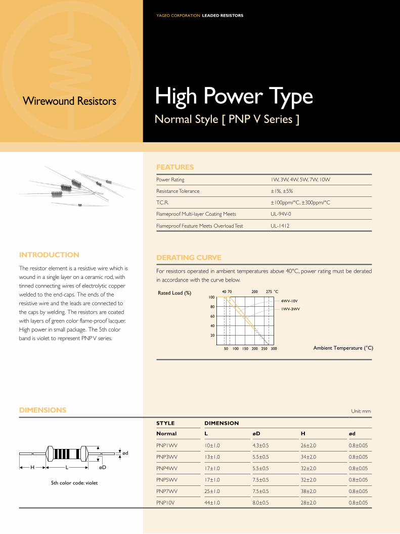
Leaded ResistoRs
diMeNsioNs Unit: mm
stYLe diMeNsioN
Normal L ød H ød
PNP1WV 10±1.0 4.3±0.5 26±2.0 0.8±0.05
PNP3WV 13±1.0 5.5±0.5 34±2.0 0.8±0.05
PNP4WV 17±1.0 5.5±0.5 32±2.0 0.8±0.05
PNP5WV 17±1.0 7.5±0.5 32±2.0 0.8±0.05
PNP7WV 25±1.0 7.5±0.5 38±2.0 0.8±0.05
PNP10V 44±1.0 8.0±0.5 28±2.0 0.8±0.05
High Power TypeNormal Style [ PNP V Series ]
iNtRodUCtioN
The resistor element is a resistive wire which is
wound in a single layer on a ceramic rod, with
tinned connecting wires of electrolytic copper
welded to the end-caps. The ends of the
resistive wire and the leads are connected to
the caps by welding. The resistors are coated
with layers of green color flame-proof lacquer.
High power in small package. The 5th color
band is violet to represent PNP V series.
FeatURes
Power Rating 1W, 3W, 4W, 5W, 7W, 10W
Resistance Tolerance ±1%, ±5%
T.C.R. ±100ppm/°C, ±300ppm/°C
Flameproof Multi-layer Coating Meets UL-94V-0
Flameproof Feature Meets Overload Test UL-1412
deRatiNG CURVe
For resistors operated in ambient temperatures above 40°C, power rating must be derated
in accordance with the curve below.
Rated Load (%)
Ambient Temperature (°C)30025020015010050
100
80
60
40
20
70
4WV-10V
1WV-3WV
200 27540 °C
ød
H L øD
th color code: violet
Wirewound Resistors

Note:
63
Note: Rated Continuous Working Voltage (RCWV) = Power Rating x Resistance Value
High Power TypeNormal Style [ PNP V Series ]
eLeCtRiCaL CHaRaCteRistiCs
stYLe PNP1WV PNP3WV PNP4WV PNP5WV PNP7WV PNP10V
Power Rating at 40°C 4W 5W 7W 10W
Power Rating at 70°C 1W 3W
Voltage Proof 300V
Resistance Range (±1%) 0.1 Ω - 1K Ω 0.1 Ω - 2.8K Ω 0.1 Ω - 4.3K Ω 0.1 Ω - 8.2K Ω 0.1 Ω - 10K Ω 0.1 Ω - 17K Ω
Resistance Range (±5%) 0.03 Ω - 1K Ω 0.015 Ω - 2.8K Ω 0.02 Ω - 4.3K Ω 0.025 Ω - 8.2K Ω 0.03 Ω - 10K Ω 0.1 Ω - 17K Ω
Operating Temp. Range -40°C to +200°C
Temperature Coefficient ±300ppm/°C
Note: Special value is available on request
eNViRoNMeNtaL CHaRaCteRistiCs
PeRFoRMaNCe test test MetHod aPPRaise
Short Time Overload IEC 60115-1 4.13 10 times rated power for 5 Sec. ±2.0%+0.05 Ω
Voltage Proof IEC 60115-1 4.7 in V-block for 60 Sec., test voltage by type By type
Temperature Coefficient IEC 60115-1 4.8 -55°C to +155°C By type
Insulation Resistance IEC 60115-1 4.6 in V-block for 60 Sec. >100M Ω
Solderability IEC 60115-1 4.17 235±5°C for 3±0.5 Sec. 95% Min. coverage
Solvent Resistance of Marking IEC 60115-1 4.30 IPA for 5±0.5 Min. with ultrasonic No deterioration of
coatings and markings
Robustness of Terminations IEC 60115-1 4.16 Direct load for 10 Sec. in the direction of the terminal leads ≥2.5kg (24.5N)
Damp Heat Steady State IEC 60115-1 4.24 40±2°C, 90-95% RH for 56 days, loaded with 0.1 times RCWV ±5.0%+0.05 Ω
Endurance at 70°C IEC 60115-1 4.25 70±2°C at RCWV for 1,000 Hr. (1.5 Hr. on, 0.5 Hr. off) ±5.0%+0.05 Ω
Temperature Cycling IEC 60115-1 4.19 -55°C Room Temp. +155°C Room Temp. (5 cycles) ±1.0%+0.05 Ω
Resistance to Soldering Heat IEC 60115-1 4.18 260±3°C for 10±1 Sec., immersed to a point 3±0.5mm from the body ±1.0%+0.05 Ω
Accidental Overload Test IEC 60115-1 4.26 4 times RCWV for 1 Min.No evidence of flaming
or arcing
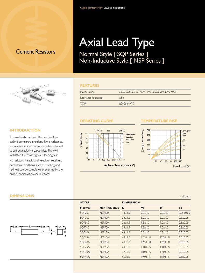
FeatURes
Power Rating 2W, 3W, 5W, 7W, 10W, 15W, 20W, 25W, 30W, 40W
Resistance Tolerance ±5%
T.C.R. ±300ppm/°C
deRatiNG CURVe teMPeRatURe Rise
Leaded ResistoRs
diMeNsioNs Unit: mm
stYLe diMeNsioN
Normal Non-inductive L W H ød
SQP200 NSP200 18±1.0 7.0±1.0 7.0±1.0 0.65±0.05
SQP300 NSP300 22±1.5 8.0±1.0 8.0±1.0 0.8±0.05
SQP500 NSP500 22±1.5 9.5±1.0 9.0±1.0 0.8±0.05
SQP700 NSP700 35±1.5 9.5±1.0 9.0±1.0 0.8±0.05
SQP10A NSP10A 48±1.5 9.5±1.0 9.0±1.0 0.8±0.05
SQP15A NSP15A 48±1.5 12.5±1.0 12.5±1.0 0.8±0.05
SQP20A NSP20A 60±5.0 12.5±1.0 12.5±1.0 0.8±0.05
SQP25A NSP25A 60±5.0 14.0±1.5 13.0±1.5 0.8±0.05
SQP30A NSP30A 77±5.0 18.0±1.5 17.0±1.5 0.8±0.05
SQP40A NSP40A 90±5.0 19.0±1.5 18.0±1.5 0.8±0.05
ød H
W32±3 32±3L
Cement ResistorsAxial Lead TypeNormal Style [ SQP Series ]Non-Inductive Style [ NSP Series ]
iNtRodUCtioN
The materials used and the construction
techniques ensure excellent flame resistance,
arc resistance and moisture resistance as well
as self-extinguishing capabilities. They will
withstand the most rigorous loading test.
As resistors in radio and television receivers,
hazardous conditions such as smoking and
redheat can be completely prevented by the
proper choice of power resistors.
300250200150100500-50
100
80
60
40
20
0
704025 155 275 °C
15W-40W3W-5W7W-10W2W
Rated Load
Ambient Temperature (°C)
(%)
12010080604020
250
300
200
150
100
50
20W-40W15W10W
7W5W
3W
2W
Tem
perature Rise
Rated Load (%)
(°C)

6
Note: Rated Continuous Working Voltage (RCWV) = Power Rating x Resistance Value
eLeCtRiCaL CHaRaCteRistiCs
NoRMaL stYLe
stYLe sQP200 sQP300 sQP500 sQP700 sQP10a sQP15a sQP20a sQP25a sQP30a sQP40a
Power Rating at 25°C 15W 20W 25W 30W 40W
Power Rating at 40°C 3W 5W 7W 10W
Power Rating at 70°C 2W
Maximum Working Voltage 250V 350V 500V 1,000V
Maximum Overload Voltage 500V 700V 1,000V 2,000V
Voltage Proof 500V 700V 1,000V 2,000V
Resistance Range (Wirewound) 0.03 Ω - 36 Ω 0.015 Ω - 68 Ω 0.015 Ω - 130 Ω 0.05 Ω - 330 Ω 0.08 Ω - 510 Ω 0.1 Ω - 680 Ω 0.15 Ω - 1K Ω
Resistance Range (Metal Oxide Film) 39 Ω - 1M Ω 75 Ω - 1M Ω 150 Ω - 1M Ω 360 Ω - 1M Ω 560 Ω - 1M Ω 750 Ω - 1M Ω 1.2K Ω - 1M Ω
Operating Temp. Range -55°C to +155°C
Temperature Coefficient ±300ppm/°C
NoN-iNdUCtiVe stYLe
stYLe NsP200 NsP300 NsP500 NsP700 NsP10a NsP15a NsP20a NsP25a NsP30a NsP40a
Power Rating at 25°C 15W 20W 25W 30W 40W
Power Rating at 40°C 3W 5W 7W 10W
Power Rating at 70°C 2W
Maximum Working Voltage 250V 350V 500V 1,000V
Maximum Overload Voltage 500V 700V 1,000V 2,000V
Voltage Proof 500V 700V 1,000V 2,000V
Resistance Range (Wirewound) 0.08 Ω - 10 Ω 0.033 Ω - 30 Ω 0.03 Ω - 40 Ω 0.15 Ω - 65 Ω 0.25 Ω - 100 Ω 0.25 Ω - 120 Ω 0.36 Ω - 160 Ω
Operating Temp. Range -55°C to +155°C
Temperature Coefficient ±300ppm/°C
Note: Special value is available on request
eNViRoNMeNtaL CHaRaCteRistiCs
PeRFoRMaNCe test test MetHod aPPRaise
Short Time Overload IEC 60115-1 4.13 2.5 times RCWV for 5 Sec. ±2.0%+0.05 Ω
Voltage Proof IEC 60115-1 4.7 in V-block for 60 Sec., test voltage by type By type
Temperature Coefficient IEC 60115-1 4.8 -55°C to +155°C By type
Insulation Resistance IEC 60115-1 4.6 in V-block for 60 Sec. >1,000M Ω
Solderability IEC 60115-1 4.17 235±5°C for 3±0.5 Sec. 95% Min. coverage
Solvent Resistance of Marking IEC 60115-1 4.30 IPA for 5±0.5 Min. with ultrasonic No deterioration of
coatings and markings
Robustness of Terminations IEC 60115-1 4.16 Direct load for 10 Sec. in the direction of the terminal leads ≥2.5kg (24.5N)
Periodic-pulse Overload IEC 60115-1 4.39 4 times RCWV 10,000 cycles (1 Sec. on, 25 Sec. off) ±2.0%+0.05 Ω
Damp Heat Steady State IEC 60115-1 4.24 40±2°C, 90-95% RH for 56 days, loaded with 0.1 times RCWV ±5.0%+0.05 Ω
Endurance at 70°C IEC 60115-1 4.25 70±2°C at RCWV for 1,000 Hr. (1.5 Hr. on, 0.5 Hr. off) ±5.0%+0.05 Ω
Temperature Cycling IEC 60115-1 4.19 -55°C Room Temp. +155°C Room Temp. (5 cycles) ±2.0%+0.05 Ω
Resistance to Soldering Heat IEC 60115-1 4.18 260±3°C for 10±1 Sec., immersed to a point 3±0.5mm from the body ±1.0%+0.05 Ω

Leaded ResistoRs
diMeNsioNs Unit: mm
stYLe diMeNsioN
Normal Non-ind. H W s P
SQM200 NSM200 20±1.5 11.0±1.0 7.0±1.0 5+2-1
SQM300 NSM300 25±1.5 12.0±1.0 8.0±1.0 5+2-1
SQM500 NSM500 25±1.5 13.0±1.0 9.0±1.0 5+2-1
SQM700 NSM700 39±1.5 13.0±1.0 9.0±1.0 5+2-1
SQM10A NSM10A 51±1.5 13.0±1.0 9.0±1.0 5+2-1
SQM10S NSM10S 35±1.5 16.0±1.0 12.0±1.0 7+2-1
FeatURes
Power Rating 2W, 3W, 5W, 7W, 10W
Resistance Tolerance ±5%
T.C.R. ±300ppm/°C
deRatiNG CURVe teMPeRatURe Rise
Cement ResistorsVertical Lead TypeNormal Style [ SQM Series ]Non-Inductive Style [ NSM Series ]
iNtRodUCtioN
The materials used and the construction
techniques ensure excellent flame resistance,
arc resistance and moisture resistance as well
as self-extinguishing capabilities. They will
withstand the most rigorous loading test.
As resistors in radio and television receivers,
hazardous conditions such as smoking and
redheat can be completely prevented by the
proper choice of power resistors.
30025020015010050-50 0
100
80
60
40
20
70
3W-5W7W-10W
2W
155 27540 °CRated Load
Ambient Temperature (°C)
(%)
12010080604020
250
200
150
100
50
10W
7W5W
3W
2W
Tem
perature Rise
Rated Load (%)
(°C)
ø08±0.05
H
P
3.5±1
W S

6
Note: Rated Continuous Working Voltage (RCWV) = Power Rating x Resistance Value
eLeCtRiCaL CHaRaCteRistiCs
NoRMaL stYLe
stYLe sQM200 sQM300 sQM500 sQM700 sQM10a sQM10s
Power Rating at 40°C 3W 5W 7W 10W
Power Rating at 70°C 2W
Maximum Working Voltage 250V 350V 500V
Maximum Overload Voltage 500V 700V 1,000V
Voltage Proof 500V 700V 1,000V
Resistance Range (Wirewound) 0.03 Ω - 36 Ω 0.015 Ω - 68 Ω 0.015 Ω - 130 Ω 0.05 Ω - 330 Ω 0.08 Ω - 510 Ω 0.03 Ω - 270 Ω
Resistance Range (Metal Oxide Film) 12 Ω - 1M Ω 75 Ω - 1M Ω 150 Ω - 1M Ω 360 Ω - 1M Ω 560 Ω - 1M Ω 300 Ω - 1M Ω
Operating Temp. Range -55°C to +155°C
Temperature Coefficient ±300ppm/°C
NoN-iNdUCtiVe stYLe
stYLe NsM200 NsM300 NsM500 NsM700 NsM10a NsM10s
Power Rating at 40°C 3W 5W 7W 10W
Power Rating at 70°C 2W
Maximum Working Voltage 250V 350V 500V
Maximum Overload Voltage 500V 700V 1,000V
Voltage Proof 500V 700V 1,000V
Resistance Range (Wirewound) 0.08 Ω - 10 Ω 0.033 Ω - 30 Ω 0.15 Ω - 65 Ω 0.25 Ω - 100 Ω 0.12 Ω - 100 Ω 0.12 Ω - 50 Ω
Operating Temp. Range -55°C to +155°C
Temperature Coefficient ±300ppm/°C
Note: Special value is available on request
eNViRoNMeNtaL CHaRaCteRistiCs
PeRFoRMaNCe test test MetHod aPPRaise
Short Time Overload IEC 60115-1 4.13 2.5 times RCWV for 5 Sec. ±2.0%+0.05 Ω
Voltage Proof IEC 60115-1 4.7 in V-block for 60 Sec., test voltage by type By type
Temperature Coefficient IEC 60115-1 4.8 -55°C to +155°C By type
Insulation Resistance IEC 60115-1 4.6 in V-block for 60 Sec. >1,000M Ω
Solderability IEC 60115-1 4.17 235±5°C for 3±0.5 Sec. 95% Min. coverage
Solvent Resistance of Marking IEC 60115-1 4.30 IPA for 5±0.5 Min. with ultrasonic No deterioration of
coatings and markings
Robustness of Terminations IEC 60115-1 4.16 Direct load for 10 Sec. in the direction of the terminal leads ≥2.5kg (24.5N)
Periodic-pulse Overload IEC 60115-1 4.39 4 times RCWV 10,000 cycles (1 Sec. on, 25 Sec. off) ±2.0%+0.05 Ω
Damp Heat Steady State IEC 60115-1 4.24 40±2°C, 90-95% RH for 56 days, loaded with 0.1 times RCWV ±5.0%+0.05 Ω
Endurance at 70°C IEC 60115-1 4.25 70±2°C at RCWV for 1,000 Hr. (1.5 Hr. on, 0.5 Hr. off) ±5.0%+0.05 Ω
Temperature Cycling IEC 60115-1 4.19 -55°C Room Temp. +155°C Room Temp. (5 cycles) ±2.0%+0.05 Ω
Resistance to Soldering Heat IEC 60115-1 4.18 260±3°C for 10±1 Sec., immersed to a point 3±0.5mm from the body ±1.0%+0.05 Ω

Leaded ResistoRs
diMeNsioNs Unit: mm
stYLe diMeNsioN
Normal Non-ind. L H W s H1
H2
P1
P2
P3
P4
SQZ300 NSZ300 24.0±1.5 9.0±1 9.0±1 10.0±1 24.0±1 9.5±1.0 4.0±0.2 2.0±0.2 5.0±0.2 1.4±0.1
SQZ500 NSZ500 27.0±1.5 9.5±1 9.5±1 15.0±1 24.0±1 9.5±1.0 4.0±0.2 2.0±0.2 5.0±0.2 1.4±0.1
SQZ700 NSZ700 35.0±1.5 9.5±1 9.5±1 22.5±1 24.0±1 9.5±1.0 4.0±0.2 2.0±0.2 5.0±0.2 1.4±0.1
SQZ10A NSZ10A 48.0±1.5 9.5±1 9.5±1 32.5±1 24.0±1 9.5±1.0 4.0±0.2 2.0±0.2 5.0±0.2 1.4±0.1
SQZ15A NSZ15A 48.0±1.5 12.5±1 12.5±1 32.5±1 34.5±1 15.0±1.5 7.0±0.2 6.0±0.2 10.0±0.2 2.7±0.1
SQZ20A NSZ20A 63.5±2.0 12.5±1 12.5±1 42.5±1 34.5±1 15.0±1.5 7.0±0.2 6.0±0.2 10.0±0.2 2.7±0.1
FeatURes
Power Rating 3W, 5W, 7W, 10W, 15W, 20W
Resistance Tolerance ±5%
T.C.R. ±300ppm/°C
deRatiNG CURVe
teMPeRatURe Rise
Cement ResistorsRadial Terminals TypeNormal Style [ SQZ Series ]Non-Inductive Style [ NSZ Series ]
iNtRodUCtioN
The materials used and the construction
techniques ensure excellent flame resistance,
arc resistance and moisture resistance as well
as self-extinguishing capabilities. They will
withstand the most rigorous loading test.
As resistors in radio and television receivers,
hazardous conditions such as smoking and
redheat can be completely prevented by the
proper choice of power resistors.
Rated Load (%)
Ambient Temperature (°C)300250200150100500-50
100
80
60
40
20
0
704025 155 275 °C
15W-20W
5W-10W
3W
Rated Load (%)12010080604020
250
300
200
150
100
50
20W15W10W
7W5W
3W
Temperature Rise (°C)
W
S
L
0.5
p1
p4
p3
p2 H
H2 H1

6
Note: Rated Continuous Working Voltage (RCWV) = Power Rating x Resistance Value
eLeCtRiCaL CHaRaCteRistiCs
NoRMaL stYLe
stYLe sQZ300 sQZ500 sQZ700 sQZ10a sQZ15a sQZ20a
Power Rating at 25°C 15W 20W
Power Rating at 40°C 5W 7W 10W
Power Rating at 70°C 3W
Maximum Working Voltage 250V 350V 500V
Maximum Overload Voltage 500V 700V 1,000V
Voltage Proof 500V 700V 1,000V
Resistance Range (Wirewound) 0.3 Ω - 130 Ω 0.36 Ω - 200 Ω 0.56 Ω - 430 Ω 1 Ω - 560 Ω 1.5 Ω - 750 Ω
Resistance Range (Metal Oxide Film) 150 Ω - 1M Ω 220 Ω - 1M Ω 300 Ω - 1M Ω 470 Ω - 1M Ω 750 Ω - 1M Ω 820 Ω - 1M Ω
Operating Temp. Range -55°C to +155°C
Temperature Coefficient ±300ppm/°C
NoN-iNdUCtiVe stYLe
stYLe NsZ300 NsZ500 NsZ700 NsZ10a NsZ15a NsZ20a
Power Rating at 25°C 15W 20W
Power Rating at 40°C 5W 7W 10W
Power Rating at 70°C 3W
Maximum Working Voltage 250V 350V 500V
Maximum Overload Voltage 500V 700V 1,000V
Voltage Proof 500V 700V 1,000V
Resistance Range (Wirewound) 0.1 Ω - 10 Ω 0.1 Ω - 20 Ω 0.1 Ω - 30 Ω
Operating Temp. Range -55°C to +155°C
Temperature Coefficient ±300ppm/°C
Note: Special value is available on request
eNViRoNMeNtaL CHaRaCteRistiCs
PeRFoRMaNCe test test MetHod aPPRaise
Short Time Overload IEC 60115-1 4.13 2.5 times RCWV for 5 Sec. ±2.0%+0.05 Ω
Voltage Proof IEC 60115-1 4.7 in V-block for 60 Sec., test voltage by type By type
Temperature Coefficient IEC 60115-1 4.8 -55°C to +155°C By type
Insulation Resistance IEC 60115-1 4.6 in V-block for 60 Sec. >1,000M Ω
Solderability IEC 60115-1 4.17 235±5°C for 3±0.5 Sec. 95% Min. coverage
Solvent Resistance of Marking IEC 60115-1 4.30 IPA for 5±0.5 Min. with ultrasonic No deterioration of
coatings and markings
Robustness of Terminations IEC 60115-1 4.16 Direct load for 10 Sec. in the direction of the terminal leads ≥2.5kg (24.5N)
Periodic-pulse Overload IEC 60115-1 4.39 4 times RCWV 10,000 cycles (1 Sec. on, 25 Sec. off) ±2.0%+0.05 Ω
Damp Heat Steady State IEC 60115-1 4.24 40±2°C, 90-95% RH for 56 days, loaded with 0.1 times RCWV ±5.0%+0.05 Ω
Endurance at 70°C IEC 60115-1 4.25 70±2°C at RCWV for 1,000 Hr. (1.5 Hr. on, 0.5 Hr. off) ±5.0%+0.05 Ω
Temperature Cycling IEC 60115-1 4.19 -55°C Room Temp. +155°C Room Temp. (5 cycles) ±2.0%+0.05 Ω
Resistance to Soldering Heat IEC 60115-1 4.18 260±3°C for 10±1 Sec., immersed to a point 3±0.5mm from the body ±1.0%+0.05 Ω

Leaded ResistoRs
Cement Resistors
Power Wirewound & Axial Lead TypeNormal & Miniature Style [ PSP Series ]
diMeNsioNs Unit: mm
stYLe diMeNsioN
Normal Miniature L W H ød
PSP400 - 20±1.0 6.4±0.3 6.4±0.3 0.8±0.02
PSP500 - 25±1.0 6.4±0.3 6.4±0.3 0.8±0.02
- PSP7WS 25±1.0 9.0±0.3 9.0±0.3 0.8±0.02
PSP700 - 38±1.0 6.4±0.3 6.4±0.3 0.8±0.02
PSP900 - 38±1.0 9.0±0.3 9.0±0.3 0.8±0.02
iNtRodUCtioN
The materials used and the construction
techniques ensure excellent flame resistance,
arc resistance and moisture resistance as well
as self-extinguishing capabilities. They will
withstand the most rigorous loading test.
As resistors in radio and television receivers,
hazardous conditions such as smoking and
redheat can be completely prevented by the
proper choice of power resistors.
FeatURes
Power Rating 4W, 5W, 7W, 9W
Resistance Tolerance ±5%, ±10%
T.C.R ±400ppm/°C
deRatiNG CURVe
For resistors operated in ambient temperatures above 70°C, power rating must be derated
in accordance with the curve below.
Rated Load (%)
Ambient Temperature (°C)300250200150100500-50
100
80
60
40
20
0
70 155 275 °C
ød
L33±3 33±3
H
W

Note:
1
Note: Rated Continuous Working Voltage (RCWV) = Power Rating x Resistance Value
eLeCtRiCaL CHaRaCteRistiCs
stYLe PsP400 PsP500 PsP7Ws PsP700 PsP900
Power Rating at 70°C 4W 5W 7W 9W
Resistance Range 0.1 Ω - 2.2K Ω 0.1 Ω - 2.5K Ω 0.5 Ω - 3.9K Ω
Operating Temp. Range -55°C to +155°C
Temperature Coefficient ±400ppm/°C
Note: Special value is available on request
eNViRoNMeNtaL CHaRaCteRistiCs
PeRFoRMaNCe test test MetHod aPPRaise
Short Time Overload IEC 60115-1 4.13 2.5 times RCWV for 5 Sec. ±2.0%+0.05 Ω
Voltage Proof IEC 60115-1 4.7 in V-block for 60 Sec., test voltage by type By type
Temperature Coefficient IEC 60115-1 4.8 -55°C to +155°C By type
Insulation Resistance IEC 60115-1 4.6 in V-block for 60 Sec. >1,000M Ω
Solderability IEC 60115-1 4.17 235±5°C for 3±0.5 Sec. 95% Min. coverage
Solvent Resistance of Marking IEC 60115-1 4.30 IPA for 5±0.5 Min. with ultrasonic No deterioration of
coatings and markings
Robustness of Terminations IEC 60115-1 4.16 Direct load for 10 Sec. in the direction of the terminal leads ≥2.5kg (24.5N)
Periodic-pulse Overload IEC 60115-1 4.39 4 times RCWV 10,000 cycles (1 Sec. on, 25 Sec. off) ±2.0%+0.05 Ω
Damp Heat Steady State IEC 60115-1 4.24 40±2°C, 90-95% RH for 56 days, loaded with 0.1 times RCWV ±5.0%+0.05 Ω
Endurance at 70°C IEC 60115-1 4.25 70±2°C at RCWV for 1,000 Hr. (1.5 Hr. on, 0.5 Hr. off) ±5.0%+0.05 Ω
Temperature Cycling IEC 60115-1 4.19 -55°C Room Temp. +155°C Room Temp. (5 cycles) ±2.0%+0.05 Ω
Resistance to Soldering Heat IEC 60115-1 4.18 260±3°C for 10±1 Sec., immersed to a point 3±0.5mm from the body ±1.0%+0.05 Ω

Leaded ResistoRs
Cement Resistors
Power Wirewound & Vertical Lead TypeNormal & Miniature Style [ PSM Series ]
iNtRodUCtioN
The materials used and the construction
techniques ensure excellent flame resistance,
arc resistance and moisture resistance as well
as self-extinguishing capabilities. They will
withstand the most rigorous loading test.
As resistors in radio and television receivers,
hazardous conditions such as smoking and
redheat can be completely prevented by the
proper choice of power resistors.
FeatURes
Power Rating 4W, 5W, 7W, 9W
Resistance Tolerance ±5%, ±10%
T.C.R ±400ppm/°C
deRatiNG CURVe
For resistors operated in ambient temperatures above 70°C, power rating must be derated
in accordance with the curve below.
diMeNsioNs Unit: mm
stYLe diMeNsioN
Normal Miniature L W H ød
PSM400 - 20±1.0 7.0±0.5 8.0±0.4 0.8±0.02
PSM500 - 25±1.0 7.0±0.5 8.0±0.4 0.8±0.02
- PSM7WS 25±1.0 9.0±0.4 10.0±0.4 0.8±0.02
PSM700 - 38±1.0 7.0±0.5 8.0±0.4 0.8±0.02
PSM900 - 38±1.0 10.0±0.4 10.0±0.4 0.8±0.02
Rated Load (%)
Ambient Temperature (°C)300250200150100500-50
100
80
60
40
20
0
70 155 275 °C
Lmax.1.5
32±3ød
H
W
H
W
PSM400-700 PSM7WS/900

Note:
3
Note: Rated Continuous Working Voltage (RCWV) = Power Rating x Resistance Value
eNViRoNMeNtaL CHaRaCteRistiCs
PeRFoRMaNCe test test MetHod aPPRaise
Short Time Overload IEC 60115-1 4.13 2.5 times RCWV for 5 Sec. ±2.0%+0.05 Ω
Voltage Proof IEC 60115-1 4.7 in V-block for 60 Sec., test voltage by type By type
Temperature Coefficient IEC 60115-1 4.8 -55°C to +155°C By type
Insulation Resistance IEC 60115-1 4.6 in V-block for 60 Sec. >1,000M Ω
Solderability IEC 60115-1 4.17 235±5°C for 3±0.5 Sec. 95% Min. coverage
Solvent Resistance of Marking IEC 60115-1 4.30 IPA for 5±0.5 Min. with ultrasonic No deterioration of
coatings and markings
Robustness of Terminations IEC 60115-1 4.16 Direct load for 10 Sec. in the direction of the terminal leads ≥2.5kg (24.5N)
Periodic-pulse Overload IEC 60115-1 4.39 4 times RCWV 10,000 cycles (1 Sec. on, 25 Sec. off) ±2.0%+0.05 Ω
Damp Heat Steady State IEC 60115-1 4.24 40±2°C, 90-95% RH for 56 days, loaded with 0.1 times RCWV ±5.0%+0.05 Ω
Endurance at 70°C IEC 60115-1 4.25 70±2°C at RCWV for 1,000 Hr. (1.5 Hr. on, 0.5 Hr. off) ±5.0%+0.05 Ω
Temperature Cycling IEC 60115-1 4.19 -55°C Room Temp. +155°C Room Temp. (5 cycles) ±2.0%+0.05 Ω
Resistance to Soldering Heat IEC 60115-1 4.18 260±3°C for 10±1 Sec., immersed to a point 3±0.5mm from the body ±1.0%+0.05 Ω
eLeCtRiCaL CHaRaCteRistiCs
stYLe PsM400 PsM500 PsM7Ws PsM700 PsM900
Power Rating at 70°C 4W 5W 7W 9W
Resistance Range 0.1 Ω - 2.2K Ω 0.1 Ω - 2.5K Ω 0.5 Ω - 3.9K Ω
Operating Temp. Range -55°C to +155°C
Temperature Coefficient ±400ppm/°C
Note: Special value is available on request

Leaded ResistoRs
Cement Resistors
Fusible Thermal & Vertical Lead TypeNormal Style [ FTR Series ]
iNtRodUCtioN
The material used and the construction
techniques ensure excellent flame resistance,
arc resistance and moisture resistance as well
as self-extinguishing capabilities. They will
withstand the most rigorous loading test.
Apply fusible thermal resistors, respond quickly
to overloading as external overheating.These
resistors also provide outstanding feature
against surges, suitable for the prevention of
inrush current for switching regulators.
FeatURes
Rated Current 2A, 3A, 5A, 10A
Resistance Tolerance ±5%, ±10%
T.C.R ±250ppm/°C
diMeNsioNs Unit: mm
stYLe diMeNsioN
Normal H W s P ød2
FTR100 25±1.5 13±1.0 9.0±1.0 5.0±1.0
0.6±0.1FTR200 38±1.5 13±1.0 9.0±1.0 5.0±1.0
FTR300 35±1.5 16±1.0 12±1.0 7.5±1.0 ød2
H
P
4.5+2/-1
W S
08±0.1

Note:
Note: Rated Continuous Working Voltage (RCWV) = Power Rating x Resistance Value
eNViRoNMeNtaL CHaRaCteRistiCs
PeRFoRMaNCe test test MetHod aPPRaise
Short Time Overload IEC 60115-1 4.13 2.5 times RCWV for 5 Sec. ±2.0%+0.05 Ω
Temperature Coefficient IEC 60115-1 4.8 -25°C to +125°C By type
Robustness of Terminations IEC 60115-1 4.16 Direct load for 10 Sec. In the direction of the terminal leads ≥25N
Damp Heat Steady State IEC 60115-1 4.24 40±2°C, 90-95% RH for 56 days, loaded with 0.1 times RCWV ±5.0%+0.1 Ω
eLeCtRiCaL CHaRaCteRistiCs
stYLe staNdaRd FUsiNG staNdaRd ResistaNCe PoWeR RatiNG at 70°C
CURReNt (a) teMPeRatURe (°C) VoLtaGe (V) RaNGe FtR100 FtR200 FtR300
FTR100 / 200 / 300 10A 109+1/-3 250 1 Ω - 10K Ω 1.2 1.4 2.0
129±4 1.6 2.0 2.5
152±4 1.6 2.0 2.5
188+3/-1 2.0 2.4 3.5
226+1/-3 2.0 2.4 3.5
5A 129±3 1.6 2.2 -
187+1/-3 2.1 2.4 -
3A 145±4 1.6 2.2 -
2A 95+3/0 0.8 1.2 -
110±4 1.2 1.4 -
126±4 1.4 1.6 -
130±4 1.6 2.1 -
135±4 1.8 2.2 -
145±4 2.1 2.4 -
Note: Special value is available on request

Leaded ResistoRs
diMeNsioNs Unit: mm
stYLe diMeNsioN
Normal a B C d ød RM
SLR200 8±1 13±1 3.5±1 5±1 0.6±0.05 9±1
SLR300 13±1 13±1 3.5±1 5±1 0.6±0.05 8±1
SLR500 18±1 14±1 3.5±1 5±1 0.6±0.05 10±1
SLR700 18±1 26±1 3.5±1 5±1 0.8±0.05 20±1
SLR10A 20±1 26±1 3.5±1 5±1 0.8±0.05 20±1
FeatURes
Power Rating 2W, 3W, 5W, 7W, 10W
Resistance Tolerance ±5%, ±10%
T.C.R. ±250ppm/°C
deRatiNG CURVe
teMPeRatURe Rise
Cement Resistors
Low Ohmic Metal Plate TypeNormal Style [ SLR Series ]
iNtRodUCtioN
The materials used and the construction
techniques ensure excellent flame resistance,
arc resistance and moisture resistance as well
as self-extinguishing capabilities. They will
withstand the most rigorous loading test.
As resistors in radio and television receivers,
hazardous conditions such as smoking and
redheat can be completely prevented by the
proper choice of power resistors.
A
C
B
RM
D
ød
Rated Load (%)
30025020015010050-50 0
100
80
60
40
20
70
3W-5W7W-10W
2W
155 27540 °C
Ambient Temperature (°C)
Temperature Rise (°C)
Rated Load (%)12010080604020
250
200
150
100
50
10W
7W5W
3W
2W
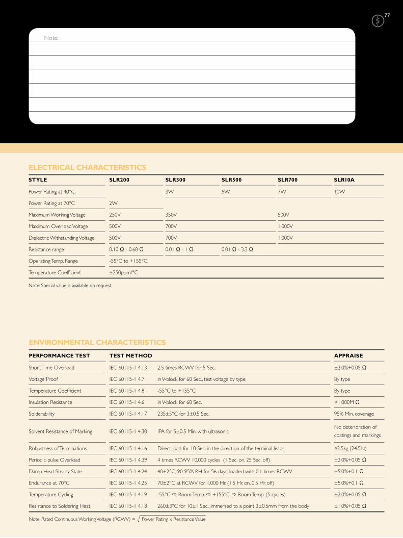
Note:
Note: Rated Continuous Working Voltage (RCWV) = Power Rating x Resistance Value
eLeCtRiCaL CHaRaCteRistiCs
stYLe sLR200 sLR300 sLR500 sLR700 sLR10a
Power Rating at 40°C 3W 5W 7W 10W
Power Rating at 70°C 2W
Maximum Working Voltage 250V 350V 500V
Maximum Overload Voltage 500V 700V 1,000V
Dielectric Withstanding Voltage 500V 700V 1,000V
Resistance range 0.10 Ω - 0.68 Ω 0.01 Ω - 1 Ω 0.01 Ω - 3.3 Ω
Operating Temp. Range -55°C to +155°C
Temperature Coefficient ±250ppm/°C
Note: Special value is available on request
eNViRoNMeNtaL CHaRaCteRistiCs
PeRFoRMaNCe test test MetHod aPPRaise
Short Time Overload IEC 60115-1 4.13 2.5 times RCWV for 5 Sec. ±2.0%+0.05 Ω
Voltage Proof IEC 60115-1 4.7 in V-block for 60 Sec., test voltage by type By type
Temperature Coefficient IEC 60115-1 4.8 -55°C to +155°C By type
Insulation Resistance IEC 60115-1 4.6 in V-block for 60 Sec. >1,000M Ω
Solderability IEC 60115-1 4.17 235±5°C for 3±0.5 Sec. 95% Min. coverage
Solvent Resistance of Marking IEC 60115-1 4.30 IPA for 5±0.5 Min. with ultrasonic No deterioration of
coatings and markings
Robustness of Terminations IEC 60115-1 4.16 Direct load for 10 Sec. in the direction of the terminal leads ≥2.5kg (24.5N)
Periodic-pulse Overload IEC 60115-1 4.39 4 times RCWV 10,000 cycles (1 Sec. on, 25 Sec. off) ±2.0%+0.05 Ω
Damp Heat Steady State IEC 60115-1 4.24 40±2°C, 90-95% RH for 56 days, loaded with 0.1 times RCWV ±5.0%+0.1 Ω
Endurance at 70°C IEC 60115-1 4.25 70±2°C at RCWV for 1,000 Hr. (1.5 Hr. on, 0.5 Hr. off) ±5.0%+0.1 Ω
Temperature Cycling IEC 60115-1 4.19 -55°C Room Temp. +155°C Room Temp. (5 cycles) ±2.0%+0.05 Ω
Resistance to Soldering Heat IEC 60115-1 4.18 260±3°C for 10±1 Sec., immersed to a point 3±0.5mm from the body ±1.0%+0.05 Ω
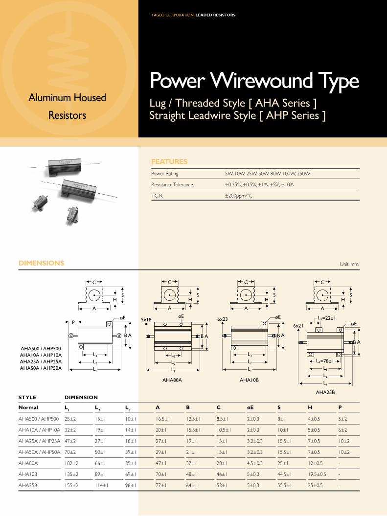
Leaded ResistoRs
Aluminum Housed
Resistors
Power Wirewound TypeLug / Threaded Style [ AHA Series ]Straight Leadwire Style [ AHP Series ]
FeatURes
Power Rating 5W, 10W, 25W, 50W, 80W, 100W, 250W
Resistance Tolerance ±0.25%, ±0.5%, ±1%, ±5%, ±10%
T.C.R. ±200ppm/°C
diMeNsioNs Unit: mm
stYLe diMeNsioN
Normal L1
L2
L3
a B C øe s H P
AHA500 / AHP500 25±2 15±1 10±1 16.5±1 12.5±1 8.5±1 2±0.3 8±1 4±0.5 5±2
AHA10A / AHP10A 32±2 19±1 14±1 20±1 15.5±1 10.5±1 2±0.3 10±1 5±0.5 6±2
AHA25A / AHP25A 47±2 27±1 18±1 27±1 19±1 15±1 3.2±0.3 15.5±1 7±0.5 10±2
AHA50A / AHP50A 70±2 50±1 39±1 29±1 21±1 15±1 3.2±0.3 15.5±1 7±0.5 10±2
AHA80A 102±2 66±1 35±1 47±1 37±1 28±1 4.5±0.3 25±1 12±0.5 -
AHA10B 135±2 89±1 69±1 70±1 48±1 46±1 5±0.3 44.5±1 19.5±0.5 -
AHA25B 155±2 114±1 98±1 77±1 64±1 53±1 5±0.3 55.5±1 25±0.5 -
B
øEP
C
A
HS
L3
L2
L1
A
C
A
HS
øE
L3
L2
L1
B A
5x18 øE
L3
L2
L1
B A
6x23
C
A
HS
=78±1
B A
6x21
C
A
HS
øE
L3
L2
L1
L4
=22±1L5
AHA00 / AHP00AHA10A / AHP10AAHA2A / AHP2AAHA0A / AHP0A
AHA80A AHA10B
AHA2B

Note: Rated Continuous Working Voltage (RCWV) = Power Rating x Resistance Value
teMPeRatURe Rise
eLeCtRiCaL CHaRaCteRistiCs
stYLe aHa500 aHa10a aHa25a aHa50a aHa80a aHa10B aHa25B
aHP500 aHP10a aHP25a aHP50a
Power Rating at 70°C 5W 10W 25W 50W 80W 100W 250W
Voltage Proof 1,000V 2,000V 4,500V
Resistance Range 0.1 Ω - 100 Ω 0.1 Ω - 3K Ω
Operating Temp. Range -55°C to +250°C
Temperature Coefficient ±200ppm/°C
Note: Special value is available on request.
Temperature (°C)
Rated Load (%)100806040
250W
80W-100W
5W-50W200
250
300
350
150
100
50
20
eNViRoNMeNtaL CHaRaCteRistiCs
PeRFoRMaNCe test test MetHod aPPRaise
Short Time Overload IEC 60115-1 4.13 2.5 times RCWV for 5 Sec. ±0.5%+0.05 Ω
Voltage Proof IEC 60115-1 4.7 in V-block for 60 Sec., test voltage by type By type
Temperature Coefficient IEC 60115-1 4.8 -55°C to +250°C By type
Insulation Resistance IEC 60115-1 4.6 in V-block for 60 Sec. >100M Ω
Solderability IEC 60115-1 4.17 235±5°C for 3±0.5 Sec. 95% Min. coverage
Solvent Resistance of Marking IEC 60115-1 4.30 IPA for 5±0.5 Min. with ultrasonic No deterioration of
coatings and markings
Pull test (30 Sec. Min): 5W: 1kg, 10W: 2.3kg, 25 - 50W: 4.5kg Robustness of Terminations IEC 60115-1 4.16
Torque test (5 - 15 Sec): 80W: 2N, 100W: 2.7N, 250W: 3.7N±0.2%+0.05 Ω
Damp Heat Steady State IEC 60115-1 4.24 40±2°C, 90-95% RH for 56 days, loaded with 0.1 times RCWV ±0.5%+0.05 Ω
Endurance at 70°C IEC 60115-1 4.25 70±2°C at RCWV for 1,000 Hr. (1.5 Hr. on, 0.5 Hr. off) ±1.5%+0.05 Ω
Temperature Cycling IEC 60115-1 4.19 -55°C Room Temp. +155°C Room Temp. (5 cycles) ±1.0%+0.05 Ω
Resistance to Soldering Heat IEC 60115-1 4.18 260±3°C for 10±1 Sec., immersed to a point 3±0.5mm from the body ±1.0%+0.05 Ω

80
exCePtioN Unit: mm
seRies PoWeR RatiNG staNdaRd Lead LeNGtH MiNiatURe Lead LeNGtH
RSF 3WM, 5SS 73 52.4
KNP / NKN / FKN 3W, 4W, 5WS 73
RSF / KNP / NKN / FKN 5W, 7W on T/R 7352.4
GeNeRaL iNFoRMatioN
PaCKiNG MetHods
The resistors are supplied on bandolier; either 1,000 resistors in ammopack or 5,000 resistors on reel.
stYLe diMeNsioNs Unit: mm
Normal Miniature a a (1) B1 - B
2s (spacing) t (Max. deviation of spacing)
52.4±1.5 1.2 TYPE-12 TYPE25S / 204 6±0.5
26.0±1.5 15
52.4±1.5 1.2TYPE-25 TYPE50S / 207 6±0.5
26.0±1.5 15
TYPE-50 TYPE1WS 6±0.5 52.4±1.5 1.2 5 1mm Per 10 Spacings, 0.5mm Per 5 Spacings
73.0±1.5 1.5TYPE100 TYPE2WS 6±0.5
52.4±1.5 1.25
TYPE200 TYPE3WS 73.0±1.5 1.5
KNP300 KNP5WS6±0.5
52.4±1.5 1.210
RSF300 RSF5WS 91.0±1.5 1.5
RSF500 / KNP500 KNP7WS6±0.5
73.0±1.5 1.510
Note: 1. Optional please refer to table "Exception"
S±0.1
T
B1 B2
A
0 +1.6/-0
1 Max.
Bandolier for Axial Leads
0.8 Max. Displacement between any two resistors
a
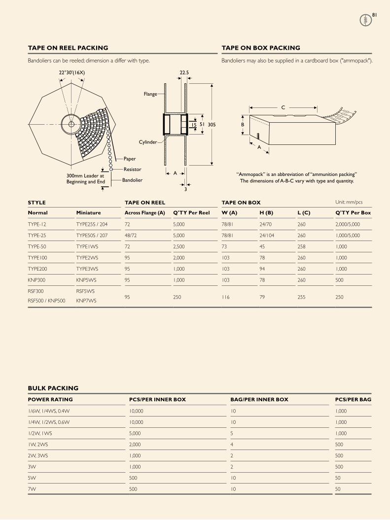
81
taPe oN ReeL PaCKiNG taPe oN Box PaCKiNG
Bandoliers can be reeled; dimension a differ with type. Bandoliers may also be supplied in a cardboard box ("ammopack").
stYLe taPe oN ReeL taPe oN Box Unit: mm/pcs
Normal Miniature across Flange (a) Q'tY Per Reel W (a) H (B) L (C) Q'tY Per Box
TYPE-12 TYPE25S / 204 72 5,000 78/81 24/70 260 2,000/5,000
TYPE-25 TYPE50S / 207 48/72 5,000 78/81 24/104 260 1,000/5,000
TYPE-50 TYPE1WS 72 2,500 73 45 258 1,000
TYPE100 TYPE2WS 95 2,000 103 78 260 1,000
TYPE200 TYPE3WS 95 1,000 103 94 260 1,000
KNP300 KNP5WS 95 1,000 103 78 260 500
RSF300 RSF5WS
RSF500 / KNP500 KNP7WS95 250 116 79 255 250
Paper
300mm Leader at Beginning and End
22°30'(16X)
5115 305
3
A
22.5
Cylinder
Bandolier
Resistor
Flange
“Ammopack” is an abbreviation of “ammunition packing” The dimensions of A-B-C vary with type and quantity.
A
B
C
BULK PaCKiNG
PoWeR RatiNG PCs/PeR iNNeR Box BaG/PeR iNNeR Box PCs/PeR BaG
1/6W, 1/4WS, 0.4W 10,000 10 1,000
1/4W, 1/2WS, 0.6W 10,000 10 1,000
1/2W, 1WS 5,000 5 1,000
1W, 2WS 2,000 4 500
2W, 3WS 1,000 2 500
3W 1,000 2 500
5W 500 10 50
7W 500 10 50

82
PaCKiNG QUaNtities
tYPe PoWeR PaCKaGe Q’tY WeiGHt CaRtoN Q’tY NW GW CaRtoN siZe CUBiC Fit
(Unit) (Watt) (Pcs) (Kg) (Pcs) (Kg) (Kg) (cm) (Cu.ft.)
Coating 1/6W Tape / Reel 5,000 1.1 50,000 11 13 60×30.5×43.5 3
Type1/4WS Tape / Box 5,000 0.74 100,000 15 16 42.5×28×35 1.5
0.4W Bulk 10,000 1.18 160,000 19 20 42.5×28×35 1.5
1/4W Tape / Reel 5,000 1.5 50,000 16 18 60×30.5×43.5 3
1/2WS Tape / Box 5,000 1.1 75,000 18 19 42.5×28×35 1.5
0.6W Bulk 10,000 1.6 80,000 12 13 42.5×28×35 1.5
1/2W Tape / Reel 2,500 1.1 25,000 11 13 60×30.5×43.5 3
1WS Tape / Box 1,000 0.43 30,000 13 14 40.5×28×33 1.4
1SS Bulk 5,000 1.86 40,000 14 15 42.5×28×35 1.5
1W Tape / Reel 2,000 2.2 20,000 22 24 60×30.5×43.5 3
2WS Tape / Box 1,000 0.9 20,000 17 18 42.5×28×35 1.5
2SS Bulk 2,000 1.4 32,000 22 23 42.5×28×35 1.5
2W Tape / Reel 1,000 1.6 10,000 13 14 60×30.5×43.5 3
3WS Tape / Box 1,000 1.12 12,000 14 15 42.5×28×35 1.5
3WV Bulk 1,000 1.02 16,000 22 24 42.5×28×35 1.5
3W Tape / Reel 250 1.4 2,000 11 13 60×30.5×43.5 3
5WS Tape / Box 250 1.02 4,000 16 17 42.5×28×35 1.5
Bulk 500 1.85 4,000 14 15 42.5×28×35 1.5
5W, 7WS Tape / Box 250 1 4,000 16 17 42.5×28×35 1.5
5SS Tape / Reel 1,000 2.5 8,000 21 23 60×30.5×43.5 3
3WM Tape / Box 500 0.93 8,000 15 16 42.5×28×35 1.5
Bulk 1,000 1.7 16,000 27 28 42.5×28×35 1.5
Jumper JPW-05 Tape / Reel 10,000 1.4 100,000 15 17 60×30.5×43.5 3
WireTape / Box 10,000 1.06 150,000 16 17 42.5×28×35 1.5
Bulk 10,000 0.98 160,000 16 17 42.5×28×35 1.5
JPW-06 Tape / Reel 10,000 1.9 100,000 22 24 60×30.5×43.5 3
Tape / Box 10,000 1.5 150,000 24 25 42.5×28×35 1.5
Bulk 10,000 1.4 160,000 23 24 42.5×28×35 1.5
JPW-07 Tape / Reel 10,000 3 100,000 32 34 60×30.5×43.5 3
JPW-08 Tape / Box 5,000 2.7 100,000 27 28 42.5×28×35 1.5
Bulk 10,000 2.5 160,000 40 41 42.5×28×35 1.5
JPW-10 Tape / Reel 10,000 5 100,000 50 52 60×30.5×43.5 3
Tape / Box 5,000 2.33 75,000 35 36 42.5×28×35 1.5
Bulk 10,000 4.7 160,000 75 76 42.5×28×35 1.5

83
PaCKiNG QUaNtities
seRies PoWeR PaCKaGe Q’tY WeiGHt CaRtoN Q’tY NW GW CaRtoN siZe CUBiC Fit
(Unit) (Watt) (Pcs) (Kg) (Pcs) (Kg) (Kg) (cm) (Cu.ft.)
SQP / NSP 2W Bulk 1,000 3.8 4,000 15 16 42.5×28×35 1.5
3W Bulk 1,000 4.6 2,000 9 10 42.5×28×35 1.5
5W Bulk 900 4.8 1,800 10 10.5 42.5×28×35 1.5
7W Bulk 500 4.5 2,000 18 19 42.5×28×35 1.5
10W Bulk 500 5.8 2,000 23 24 42.5×28×35 1.5
15W Bulk 50 1.1 1,000 20 21 42.5×28×35 1.5
20W Bulk 50 1.4 1,000 27 28 42.5×28×35 1.5
25W Bulk 50 1.5 250 7 8 42.5×28×35 1.5
30W Bulk 50 3.3 250 16 17 42.5×28×35 1.5
40W Bulk 50 3.9 250 19 20 42.5×28×35 1.5
SQM / NSM 2W Bulk 1,500 8.3 3,000 16.5 18 42.5×28×35 1.5
3W Bulk 1,500 9.1 3,000 18 19 42.5×28×35 1.5
5W Bulk 1,000 6.6 2,000 13 14 42.5×28×35 1.5
7W Bulk 800 8.1 3,200 32 33 42.5×28×35 1.5
10W Bulk 500 8.6 2,000 34 35 42.5×28×35 1.5
10WS Bulk 90 1.5 2,700 42 43 42.5×28×35 1.5
SQZ / NSZ 3W Bulk 150 0.9 2,400 14 15 42.5×28×35 1.5
5W Bulk 150 1.0 2,400 16 16.5 42.5×28×35 1.5
7W Bulk 150 1.6 2,400 24 25 42.5×28×35 1.5
10W Bulk 150 2.1 2,400 33 34 42.5×28×35 1.5
15W Bulk 50 1.1 800 17 18 42.5×28×35 1.5
20W Bulk 50 1.4 800 21 22 42.5×28×35 1.5
SLR 2W Bulk 1,000 1.6 8,000 12 13 42.5×28×35 1.5
3W Bulk 1,000 2.2 8,000 17 18.3 42.5×28×35 1.5
5W Bulk 240 0.9 4,800 17 18 42.5×28×35 1.5

84
FoRMiNG diMeNsioN (sPeCiaL tYPe)
M tYPe
stYLe diMeNsioNs Unit: mm
Normal Miniature L P ød ød H
TYPE-12 TYPE25S 3.4±0.3 6.0±1 1.9±0.2 0.45±0.05 10.0±1
TYPE-25 TYPE 50S 6.3±0.5 10.0±1 2.4±0.2 0.55±0.05 10.0±1
TYPE-50 TYPE1WS 9.0±0.5 12.5±1 3.3±0.3 0.55±0.05 10.0±1
TYPE100 TYPE2WS 11.5±1.0 15.0±1 4.5±0.5 0.8±0.05 12.5±1
TYPE200 TYPE3WS 15.5±1.0 20.0±1 5.0±0.5 0.8±0.05 15.0±1
MB tYPe
stYLe diMeNsioNs Unit: mm
Normal Miniature L P ød ød H1
H2
t
TYPE-25 TYPE50S 6.3±0.5 10.0±1 2.4±0.2 0.55±0.05 6.0±1 5.0±1 1.2±0.2
TYPE-50 - 9.0±0.5 12.5±1 3.3±0.3 0.55±0.05 6.0±1 5.0±1 1.2±0.2
- TYPE1WS 9.0±0.5 12.5±1 3.3±0.3 0.8±0.05 6.0±1 5.0±1 1.4±0.2
TYPE100 TYPE2WS 11.5±1.0 15.0±1 4.5±0.5 0.8±0.05 6.0±1 5.0±1 1.4±0.2
TYPE200 TYPE3WS 15.5±1.0 20.0±1 5.0±0.5 0.8±0.05 10.0±1 5.0±1 1.4±0.2
TYPE300 TYPE5WS 24.5±1.0 30.0±1 8.0±0.5 0.8±0.05 15.0±1 5.0±1 1.4±0.2
TYPE500 - 24.5±1.0 30.0±1 8.0±0.5 0.8±0.05 15.0±1 5.0±1 1.4±0.2
MR tYPe
stYLe diMeNsioNs Unit: mm
Normal Miniature L P F ød ød H1
H2
TYPE-50 TYPE1WS 9.0±0.5 14.5±1 7.0±0.5 3.3±0.3 0.55±0.05 7.0±1 5.0±1
TYPE100 TYPE2WS 11.5±1.0 17.5±1 7.0±0.5 4.5±0.5 0.8±0.05 8.0±1 5.0±1
TYPE200 TYPE3WS 15.5±1.0 21.5±1 7.0±0.5 5.0±0.5 0.8±0.05 9.0±1 5.0±1
H1
H2
L
P
ød
øD
0-3.0
t
0-3.0
øDL
H1
H2
FP
ød
øD
0-3.0
H
P
ød
L

8
F tYPe FK tYPe FFK tYPe FKK tYPe
stYLe diMeNsioNs Unit: mm
Normal Miniature L P ød ød h H Max. h1 H1 Max. e Max.
TYPE100 TYPE2WS 11.5±1 6±1 4.5±0.5 0.8±0.05 10.0±1 25 5.0±1 20 3.5
TYPE200 TYPE3WS 15.5±1 6±1 5.0±0.5 0.8±0.05 10.0±1 30 5.0±1 25 3.5
Note: TYPE-25/50S is available.
aV type Forming for taping
Rated Watts 1/4W, 1/2WS & 0.6W
Body Dimension : L = 6.3±0.5mm
øD = 2.4±0.2mm
Rated Watts : 1/2W & 1WS
Body Dimension : L = 9±0.5mm
øD = 3.3±0.3mm
Rated Watts : 1W & 2WS
Body Dimension : L = 11.5±1.0mm
øD = 4.5±0.5mm
PN type Forming for taping
Rated Watts 1/4W, 1/2WS & 0.6W
Body Dimension : L = 6.3±0.5mm
øD = 2.4±0.2mm
Rated Watts : 1/2W & 1WS
Body Dimension : L = 9±0.5mm
øD = 3.3±0.3mm
Rated Watts : 1W & 2WS
Body Dimension : L = 11.5±1.0mm
øD = 4.5±0.5mm
12.±0.
.0±0.
12.±0.34.0±0.3
-0.
18.0
+1.
0
-0
16.0
+1.
0
1 Max.
12.±0.
.0±0.
12.±0.3 1 Max. 4.0±0.3
-0.
18.0
+1.
0
-016
.0+
1.0
Ft type Forming for taping
Rated Watts 1/4W, 1/2WS & 0.6W
Body Dimension : L = 6.3±0.5mm
øD = 2.4±0.2mm
Rated Watts : 1/2W & 1WS
Body Dimension : L = 9±0.5mm
øD = 3.3±0.3mm
Rated Watts : 1W & 2WS
Body Dimension : L = 11.5±1.0mm
øD = 4.5±0.5mm
Mt type Forming for taping
Rated Watts 1/6W, 1/4WS & 0.4W
Body Dimension : L = 3.4±0.3mm
øD = 1.9±0.2mm
12.±0.
.0±0.
12.±0.34.0±0.3
-0.
18.0
+1.
0
-016
.0+
1.0
1 Max.
12.±0.3
6.3±1.0.0+0.4
-0.2
.0±0.
12.±0.3 0.4 or 0. 4.0±0.3
-0.
18.0
+1.
0
20.0
+0.
-0
FK TYPE FFK TYPE FKK TYPE
øD
E
L
h
H
ød
P
øD
E
L
h
H
ød
P
øD
E
L
h
H
ødP
F TYPE
øD
H1
Pød
hI
L
E

86
exPLaNatioNs oF oRdeRiNG Code
exCePtioN:
• Cement series: • JPW series:
<Code 8>: Special packing style code
B: Bulk with wirewound or metal oxide sub-assembly for resistance value
W: Bulk with wirewound sub-assembly for resistance value
M: Bulk with metal oxide sub-assembly for resistance value
<Code 10-12>: Without forming code
Example: SQP00JB-10R
<Code 13-17>: without resistance value code
Example: JPW-06-T-2-
-12Code 4 - 6
Power Rating
-05 = ød0.5mm
-06 = ød0.6mm
-07 = ød0.7mm
-08 = ød0.8mm
-10 = ød1.0mm
-14 = ød1.4mm
-12 = 1/6W
-25 = 1/4W
25S = 1/4WS
-50 = 1/2W
50S = 1/2WS
100 = 1W
1WS = 1WS
200 = 2W
2WS = 2WS
204 = 0.4W
207 = 0.6W
300 = 3W
3WS = 3WS
3WM = 3WM
400 = 4W
500 = 5W
5WS = 5WS
5SS = 5WSS
700 = 7W
7WS = 7WS
10A = 10W
20A = 20W
30A = 30W
40A = 40W
50A = 50W
10S = 10WS
15A = 15W
25A = 25W
10B = 100W
25B = 250W
FCode 7
tolerance
P = ±0.02 %
A = ±0.05 %
B = ±0.1 %
C = ±0.25%
D = ±0.5 %
F = ±1 %
G = ±2 %
J = ±5 %
K = ±10 %
- = Base on Spec.
tCode 8
Packing style
T = Tape/Box
R = Tape/Reel
B = Bulk
FCode 9
temperature Coef-
ficient of Resistance
- = Base on Spec.
A = ±5 ppm/°C
B = ±10 ppm/°C
C = ±15 ppm/°C
D = ±25 ppm/°C
E = ±50 ppm/°C
F = ±100 ppm/°C
G = ±200 ppm/°C
H = ±250 ppm/°C
I = ±300 ppm/°C
J = ±350 ppm/°C
52-Code 10 - 12
Forming type
26- = 26mm
52- = 52.4mm
73- = 73mm
81- = 81mm
91- = 91mm
F = F Type
FK = FK Type
FKK = FKK Type
FFK = F-form Kink
M = M-Type Forming
MB = M-form W/flat
MT = MT Type Forming
MR = MR Type
AV = AVIsert
PN = PANAsert
100RCode 13 - 17
Resistance Value
0R1 = 0.1
100R = 100
10K = 10,000
10M = 10,000,000
MFRCode 1 - 3
series Name
See Index

8
4-BAND-CODE
5-BAND-CODE
2%, 5%, 10% 560KΩ ±5%
237Ω ±1%0.1%, 0.25%, 0.5%, 1%
1st BAND 2nd BAND 3rd BAND MULTIPLIER TOLERANCE
(F)
222 (G)
555 (D)
(C)
777 (B)
888
9990.1 ( J )
0.01 (K)
1Ω
±1%
±2%
±0.5%
±0.25%
±0.10%
±0.05%
±5%
±10%
10Ω
100Ω
1KΩ
10KΩ
100KΩ
1MΩ
10MΩ
COLOR
BLACK
RED
ORANGE
YELLOW
GREEN
BLUE
VIOLET
GREY
WHITE
GOLD
SILVER
BROWN
MaRKiNG aNd staNdaRd ResistaNCe VaLUe FoR tHe 10-to-100 deCade
staNdaRd ResistaNCe VaLUes FoR tHe 10-to-100 deCade(Also Usable in Decade Multiples or Sub-Multiples)
RESISTANCE TOLERANCE (±%)0.10% 2% 0.10% 2% 0.10% 2% 0.10% 2% 0.10% 2% 0.10% 2%
0.25% 1% 5% 0.25% 1% 5% 0.25% 1% 5% 0.25% 1% 5% 0.25% 1% 5% 0.25% 1% 5%
0.50% 10% 0.50% 10% 0.50% 10% 0.50% 10% 0.50% 10% 0.50% 10%
10 10 10 14.7 14.7 - 21.5 21.5 - 31.6 31.6 - 46.4 46.4 - 68.1 68.1 68
10.1 - - 14.9 - - 21.8 - - 32 - - 47 - 47 69 - -
10.2 10.2 - 15 15 15 22.1 22.1 22 32.4 32.4 - 47.5 47.5 - 69.8 69.8 -
10.4 - - 15.2 - - 22.3 - - 32.8 - - 48.1 - - 70.6 - -
10.5 10.5 - 15.4 15.4 - 22.6 22.6 - 33.2 33.2 33 48.7 48.7 - 71.5 71.5 -
10.6 - - 15.6 - - 22.9 - - 33.6 - - 49.3 - - 72.3 - -
10.7 10.7 - 15.8 15.8 - 23.2 23.2 - 34 34 - 49.9 49.9 - 73.2 73.2 -
10.9 - - 16 - 16 23.4 - - 34.4 - - 50.5 - - 74.1 - -
11 11 11 16.2 16.2 - 23.7 23.7 - 34.8 34.8 - 51.1 51.1 51 75 75 75
11.1 - - 16.4 - - 24 - 24 35.2 - - 51.7 - - 75.9 - -
11.3 11.3 - 16.5 16.5 - 24.3 24.3 - 35.7 35.7 - 52.3 52.3 - 76.8 76.8 -
11.4 - - 16.7 - - 24.6 - - 36.1 - 36 53 - - 77.7 - -
11.5 11.5 - 16.9 16.9 - 24.9 24.9 - 36.5 36.5 - 53.6 53.6 - 78.7 78.7 -
11.7 - - 17.2 - - 25.2 - - 37 - - 54.2 - - 79.6 - -
11.8 11.8 - 17.4 17.4 - 25.5 25.5 - 37.4 37.4 - 54.9 54.9 - 80.6 80.6 -
12 - 12 17.6 - - 25.8 - - 37.9 - - 55.6 - - 81.6 - -
12.1 12.1 - 17.8 17.8 - 26.1 26.1 - 38.3 38.3 - 56.2 56.2 56 82.5 82.5 82
12.3 - - 18 - 18 26.4 - - 38.8 - - 56.9 - - 83.5 - -
12.4 12.4 - 18.2 18.2 - 26.7 26.7 - 39.2 39.2 39 57.6 57.6 - 84.5 84.5 -
12.6 - - 18.4 - - 27.1 - 27 39.7 - - 58.3 - - 85.6 - -
12.7 12.7 - 18.7 18.7 - 27.4 27.4 - 40.2 40.2 - 59 59 - 86.6 86.6 -
12.9 - - 18.9 - - 27.7 - - 40.7 - - 59.7 - - 87.6 - -
13 13 13 19.1 19.1 - 28 28 - 41.2 41.2 - 60.4 60.4 - 88.7 88.7 -
13.2 - - 19.3 - - 28.4 - - 41.7 - - 61.2 - - 89.8 - -
13.3 13.3 - 19.6 19.6 - 28.7 28.7 - 42.2 42.2 - 61.9 61.9 62 90.9 90.9 91
13.5 - - 19.8 - - 29.1 - - 42.7 - - 62.6 - - 92 - -
13.7 13.7 - 20 20 20 29.4 29.4 - 43.2 43.2 43 63.4 63.4 - 93.1 93.1 -
13.8 - - 20.3 - - 29.8 - - 43.7 - - 64.2 - - 94.2 - -
14 14 - 20.5 20.5 - 30.1 30.1 30 44.2 44.2 - 64.9 64.9 - 95.3 95.3 -
14.2 - - 20.8 - - 30.5 - - 44.8 - - 65.7 - - 96.5 - -
14.3 14.3 - 21 21 - 30.9 30.9 - 45.3 45.3 - 66.5 66.5 - 97.6 97.6 -
14.5 - - 21.3 - - 31.2 - - 45.9 - - 67.3 - - 98.8 - -
e-192 e-96 e-24 e-192 e-96 e-24 e-192 e-96 e-24 e-192 e-96 e-24 e-192 e-96 e-24 e-192 e-96 e-24

Note:

Note:

Note:


Date of release: December 2010Printed in Taiwan Document order number: YL 100 00126
© YaGeo Corporation
All rights are reserved. Reproduction in whole or in part is prohibited without the prior written consent of the copyright owner.The information presented in this document does not form part of any quotation or contract, is believed to be accurate and reliable and may be changed without notice.
No liability will be accepted by the publisher for any consequence of its use. Publication thereof does not convey nor imply any license under patent or other industrial or intellectual property rights.
For more detailed and always up-to-date contact details of sales offices, distributors and representatives, please go to our website at
www.yageo.com
asia
Beijing, ChinaTel. +86 10 81 20810Fax. +86 10 81 20200
dongguan, ChinaTel. +86 6 82 02Fax. +86 6 81 003
Hong Kong, ChinaTel. +82 2342 6833Fax. +82 2342 688
Mudu, ChinaTel. +86 12 661 888Fax. +86 12 661 88
Qingdao, ChinaTel. +86 1 22 40
Fax. +86 12 682 68 x 2688
suzhou, ChinaTel. +86 12 682 68Fax. +86 12 682 386
Wuhan, ChinaTel. +86 2 83 83Fax. +86 2 83 83
saitama, JapanTel. +81 48 83Fax. +81 48 84
Kyunggi-do, KoreaTel. +82 31 12 4Fax. +82 31 12 866
Kuala Lumpur, MalaysiaTel. +60 3 8063 8864Fax. +60 3 8063 36
singaporeTel. +6 6244 800Fax. +6 6244 443
taipei, taiwanTel. +886 2 21 Fax. +886 2 21 4286
eURoPe
Roermond, BeneluxTel. +31 4 38 Fax. +31 4 38 8
suresnes, FranceTel. +33 1 46 14 8 1Fax. +33 1 46 14 8 2
Hamburg, GermanyTel. +4 4121 80 18Fax. +4 4121 80 21
szombathely, HungaryTel. +36 30 3 441Fax. +36 4 1 01
Milan, italy Tel. +3 02 612 101Fax. +3 02 6601 40
Moscow, Russian FederationTel. + 16 62 2 38Fax. + 48 610 0 0
Barcelona, spainTel. +34 3 212 32
Fax. +3 02 6601 40
Berkshire, UKTel. +44 6 346 60 Fax. +31 4 38 8
NoRtH aMeRiCa
san Jose, U.s.a. Tel. +1 408 240 6200Fax. +1 408 240 6201
YaGeo - a GLoBaL CoMPaNY