Lead-Free For Mixed Technology Circuit Boards - … · Lead-Free Solder Assembly For Mixed...
9
Lead-Free Solder Assembly For Mixed Technology Circuit Boards AIM Several lead-free alloys have been investigated for SMT assembly. The industry has migrated to a family of alloys know as SAC (Tin/Silver/Copper) alloys, and within this group the industry has narrowed its focus to the SAC305 (96.5% tin, 3% silver, 0.5% copper) alloy. The Solder Products Value Council (SPVC) under the guidance of the IPC has completed a million dollar, year-long study that has recently confirmed that SAC305 is the recommended default SMT alloy 1 . However, it is well known that SAC305 can cause negative results in wave soldering, hand soldering and selective soldering applications. For example, due to solder volume and solder joint configuration, SAC alloys often suffer from “hot tears/shrink holes” 2 . These shrink holes can be difficult to distinguish between a “cold” joint and a good joint, thus causing inspection difficulties. In addition, the cost of SAC305, although the lowest of the SAC family, is higher than other alloys due to its silver content. Primarily for these two reasons, the industry is looking for alternative alloys for non-SMT applications. The common alternative alloys are SN100C 3 , SAC-LOW, and SACX 4 . The issue of choosing a wave solder or selective solder alloy is more complicated than choosing an SMT alloy because not only do these solders have to form a reliable solder joint, but they also are used in a molten solder bath. How these alloys react to molten solder baths is what differentiates them from one another. The SAC and SACX alloys dissolve most metals they come in contact with over time. For these alloys, new soldering equipment parts are necessary to keep equipment maintenance to a minimum. Contrarily, the SN100C and SAC-LOW alloys contain additives (dopants) to reduce their aggressiveness to the contact parts in the solder pot. Additionally, this also reduces copper corrosion, which is important when running selective soldering for rework applications. The below data clearly demonstrates that SN100C is less likely to remove pads and traces from circuit boards during extended working times. 1 This study is available through the IPC at www.ipc.org 2 As referred to in IPC-A-610 Rev D 3 Sn/Cu/Ni alloy patented by Nihon Superior 4 Sn/Cu/Ag/Bi alloy patented by Alpha Metals
Transcript of Lead-Free For Mixed Technology Circuit Boards - … · Lead-Free Solder Assembly For Mixed...

Lead-Free Solder Assembly For Mixed Technology Circuit Boards AIM
Several lead-free alloys have been investigated for SMT assembly. The industry has migrated to a family of alloys know as SAC (Tin/Silver/Copper) alloys, and within this group the industry has narrowed its focus to the SAC305 (96.5% tin, 3% silver, 0.5% copper) alloy. The Solder Products Value Council (SPVC) under the guidance of the IPC has completed a million dollar, year-long study that has recently confirmed that SAC305 is the recommended default SMT alloy1. However, it is well known that SAC305 can cause negative results in wave soldering, hand soldering and selective soldering applications. For example, due to solder volume and solder joint configuration, SAC alloys often suffer from “hot tears/shrink holes”2. These shrink holes can be difficult to distinguish between a “cold” joint and a good joint, thus causing inspection difficulties. In addition, the cost of SAC305, although the lowest of the SAC family, is higher than other alloys due to its silver content. Primarily for these two reasons, the industry is looking for alternative alloys for non-SMT applications. The common alternative alloys are SN100C3, SAC-LOW, and SACX4. The issue of choosing a wave solder or selective solder alloy is more complicated than choosing an SMT alloy because not only do these solders have to form a reliable solder joint, but they also are used in a molten solder bath. How these alloys react to molten solder baths is what differentiates them from one another. The SAC and SACX alloys dissolve most metals they come in contact with over time. For these alloys, new soldering equipment parts are necessary to keep equipment maintenance to a minimum. Contrarily, the SN100C and SAC-LOW alloys contain additives (dopants) to reduce their aggressiveness to the contact parts in the solder pot. Additionally, this also reduces copper corrosion, which is important when running selective soldering for rework applications. The below data clearly demonstrates that SN100C is less likely to remove pads and traces from circuit boards during extended working times.
1 This study is available through the IPC at www.ipc.org 2 As referred to in IPC-A-610 Rev D 3 Sn/Cu/Ni alloy patented by Nihon Superior 4 Sn/Cu/Ag/Bi alloy patented by Alpha Metals
0
20
40
60
80
100
120
0 50 100
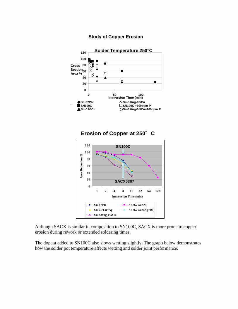
Sn-37Pb SN100C Sn-0.65Cu
Sn-3.0Ag-0.5Cu SN100C +100ppm P Sn-3.0Ag-0.5Cu+100ppm P
Solder Temperature 250°C
Cross Section Area %
Immersion Time (min)
Study of Copper Erosion
0
20
40
60
80
100
120
1 2 4 8 16 32 64 128
Immersion Time (min)
Are
a R
educ
tion
%
Sn-37Pb Sn-0.7Cu+NiSn-0.7Cu+Ag Sn-0.7Cu+(Ag+Bi)Sn-3.0Ag-0.5Cu
Erosion of Copper at 250°C
SN100C
SACX0307
Although SACX is similar in composition to SN100C, SACX is more prone to copper erosion during rework or extended soldering times. The dopant added to SN100C also slows wetting slightly. The graph below demonstrates how the solder pot temperature affects wetting and solder joint performance.

0.00
0.10
0.20
0.30
0.40
0.50
250°C 260°C 270°C
Solder Temperature
Wet
ting
Tim
e t1
(sec
)Sn-37PbSn-0.7Cu+NiSn-0.7Cu+AgSn-0.7Cu+(Ag+Bi)Sn-3.0Ag-0.5Cu
Wetting time as a function of test temperature
SN100C
SACX0307
As seen above, when the recommended soldering temperature is used, the wetting is very similar between SN100C and SACX. Wave pot temperatures should be from 265 to 270°C to achieve maximum wetting and, depending on board layout, the dwell time in the wave should be ~5 seconds. This dwell time is longer than conventional tin-lead profiles; however, the extended dwell time will help topside solder fillet formation. SACX also has a dull appearance and suffers from micro-cracks or the aforementioned “Hot tears/shrink holes”. This also can lead to inspection problems.
SACX SN100C
Voiding in PTH Joints Another issue to consider is voiding in the PTH barrels. The SAC alloys are prone to more voiding than alternative alloys. This is typical for a SAC wave soldering application and may or may not cause a reliability issue. In terms of joint strength, SAC alloys have more than ample joint strength, even with the voids. However, if the leads are used for high power, resistance or temperature dissipation might be an issue. The following pictures are a comparison of ENIG boards soldered with SAC and SN100C. The SN100C solder joint are consistently lower voiding and have very good fillet formation.

SAC SN100C
SAC SN100C
In addition to voiding less, SN100C is also less prone to surface cracks that form due to cooling rate along intermetallic grain boundaries. This results in fewer cracks and shinier solder joints and an appearance very similar to tin-lead solder joints. Lead-Free Alloy “Cross Contamination” Many assemblers want to use one alloy throughout all soldering processes in order to avoid “cross contamination”. The contamination of lead-free solder joints from exposure to tin-lead can be detrimental and has been documented in “Lead Contamination in Lead-Free Electronics Assembly”5 as well as several other publications. Little work, however, has been done on the mixture of different lead-free alloys in the same solder joint. This type of mixture could stem from using the wrong repair solder or board designs that do not allow enough space between SMT and wave pads. Unfortunately, fear of contaminating one lead-free alloy with another has kept manufactures using a one alloy system, despite the fact that SAC may not be the best choice for wave, selective, or hand soldering. This paper addresses the issue of mixed lead-free solders. During typical SMT assembly, there are few places that solder can cross contaminate other than BGA assembly, in which the solder connection itself is a combination of solder ball and solder paste. As an aside, many of these lead-free BGA balls are a 5 This paper may be downloaded at www.leadfree.com

proprietary alloy mixture similar to SAC alloys. The reason that SAC is not used is because these alloys do not have as good as a drop shock test properties as tin-lead. Therefore, alloys doped with antimony, nickel, germanium, indium, silicon, and other elements are used to improve this particular characteristic. These solder balls are then soldered with SAC during SMT applications without any issue. However, soldering with SAC to a tin-lead solder ball gives much poorer results due to excessive voiding and a segregated joint that will fail at lower forces than either alloy independently. PTH Cross Contamination As the below images demonstrate, the only alloy combination found to be detrimental to solder joint life during the wave soldering test for cross contamination was lead in SAC or any other lead-free alloy.

From the above pictures and cross sections, SAC and SN100C were found to be compatible with one another when mixed by using a different touch up wire alloy as the alloy used in the wave. Therefore, there would not be any detrimental effect by the accidental mixing of these alloys. SMT Cross Contamination Because they are found on both sides of the circuit board and can be soldered with solder paste in an SMT reflow process or glued and soldered in a wave solder process, chip resisters and capacitors are the SMT components most likely to become cross contaminated. If touch up or repair is required, it is likely that these solder joints may
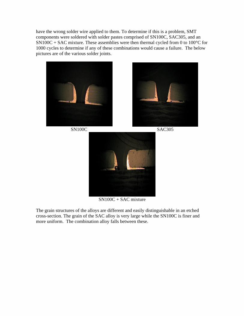
have the wrong solder wire applied to them. To determine if this is a problem, SMT components were soldered with solder pastes comprised of SN100C, SAC305, and an SN100C + SAC mixture. These assemblies were then thermal cycled from 0 to 100°C for 1000 cycles to determine if any of these combinations would cause a failure. The below pictures are of the various solder joints.
SN100C SAC305
SN100C + SAC mixture
The grain structures of the alloys are different and easily distinguishable in an etched cross-section. The grain of the SAC alloy is very large while the SN100C is finer and more uniform. The combination alloy falls between these.

SN100C SAC
SN100C + SAC mixture
Thermal Cycling Test Results The SAC, SN100C and SN100C + SAC mixture all performed the same in thermal cycling testing. None of the boards that were assembled and thermal cycled had any solder joint failures. From this initial testing on the SMT joints and the more extensive testing on the through hole joints, it does not appear that the cross contamination between SAC and SN100C alloys has any negative effect on solder joint reliability based on thermal cycles. The SAC, SN100C and SN100C + SAC mixture were each tested for shear strength of the components before and after thermal testing. The components were tested using a destructive shear test to measure the relative solder joint strengths. The test consisted of a Chatillon TCM 201 SS coupled with a Chatillon DFIS-50 Force Gauge. Downward force speed was 0.25 inches per minute. The results of the shear testing are as follows.
Alloy 0 cycles 1000 cycles SAC305 15.3 lbs 15 lbs SN100C + SAC mix 14.1 lbs 14.3 lbs SN100C 14.2 lbs 14.0 lbs

Sn/Pb 14.8 lbs 14.5 lbs The results show that solder joints made with SAC, SN100C and the SN100C + SAC mixture are all comparable to tin-lead solder joints made on the same board. In addition, it was determined that thermal cycling does not seem to degrade these solder joints. Conclusion Based on results from this testing, no degradation of the solder joint was found due to mixing SN100C with SAC alloy. Therefore it is believed that a two alloy system can be successfully used for mixed technology boards without compromising reliability.
AIM Manufacturing and Distribution Worldwide
Americas +1-401-463-5605 • Europe +44-1737-222-258 • Asia-Pacific +852-2649-7183 • [email protected] • www.aimsolder.com