Leaching of rare earth elements from eudialyte concentrate ... · Leaching of rare earth elements...
8
Leaching of rare earth elements from eudialyte concentrate by suppressing silica gel formation P. Davris a,⇑ , S. Stopic b , E. Balomenos a , D. Panias a , I. Paspaliaris a , B. Friedrich b a National Technical University of Athens (NTUA), School of Mining and Metallurgical Engineering, 15780 Zografos, Greece b Institute of Process Metallurgy and Metal Recycling (IME), RWTH Aachen University, Intzestrabe 3, 52056 Aachen, Germany article info Article history: Received 6 September 2016 Revised 15 December 2016 Accepted 16 December 2016 Available online 29 December 2016 Keywords: Eudialyte Rare earth elements Silica gel Leaching Fuming abstract In this study a two stage hydrometallurgical treatment of eudialyte concentrate is presented, aiming on recovering rare earth elements and suppressing silica gel formation, The proposed treatment incorpo- rates a preprocessing step called ‘‘Fuming”, which is the addition of an acidic solution to eudialyte con- centrate heated at boiling temperatures, followed by the leaching step, where the treated concentrate is leached at ambient or low temperature. Fuming pretreatment with sulfuric or hydrochloric acid, and sub- sequently water leaching of the treated concentrate, resulted to >90% recovery of rare earths avoiding sil- ica gel formation which is a major challenge to overcome during eudialyte dissolution. Scanning electron microscopy analysis, indicate that ‘‘Fuming”, transforms eudialyte into a mixture of metal salts and a siliceous secondary precipitate. Leaching of the treated concentrate dissolves soluble metal salts into solution whereas the secondary siliceous precipitate remains in the residue with the rest gangue miner- als such as aegirine and feldspar. Advantages of the proposed treatment are low acid consumption, high rare earth recovery yields, avoidance of additives such as fluoride ions and avoidance of silica gel formation. Ó 2016 Elsevier Ltd. All rights reserved. 1. Introduction Rare-earth elements (REEs) consist of scandium, yttrium and lanthanides exhibiting similar chemical properties. Demand for rare earth elements has spiked in recent years due to their increas- ing usage as enablers in numerous high-technology applications, including a variety of renewable energy technologies like hybrid cars, wind turbines, solid oxide fuel cells and others (Nagaiyar Krishnamurthy, 2015). REE are essentials towards a cleaner, greener future (Binnemans et al., 2013), thus future demand of these metals is likely to increase rapidly. As such, the European Commission (ERECON, 2015; EU, 2014) and the US Department of Energy (US, 2011) labeled the REEs among the most critical raw materials in terms of supply risk and economic importance. The total REE production in 2014 estimated to be 110,000 tons with China being the dominant producer (Gambogi, 2015). Despite the great variation that exhibits in REE prices (Golev et al., 2014), the demand particularly for Nd and Dy, which are indispensable in the manufacture of high strength permanent magnets, is antic- ipated to increase by 700% and 2600% in the next 25 years, respec- tively (Alonso et al., 2012). Predominantly minerals used in extractive metallurgy of REEs are monazite, bastnäsite and a ion- adsorption clays, processed mainly in China (Habashi, 2013; Nagaiyar Krishnamurthy, 2015). Among the several minerals that have been found to contain REEs and occur in potential economic deposits, an interesting resource of heavy rare earths (HREE), espe- cially of Y and Dy, is the mineral group of Eudialyte. Eudialyte is a complex Na-Ca-zirconosilicate mineral containing economically attractive levels of Zr, Nb and REE whereas its geological alteration provides variable REE/Zr mineralization (Borst et al., 2016). Eudia- lyte chemistry has great compositional variability. Its structure involves silica-oxygen nine membered rings, Si 9 O 27 and six mem- bered calcium octahedra rings, Ca 6 O 24 which are linked together with three membered Si 3 O 9 rings and ZrO 6 octahedra into a zeolite like framework. In this framework vacancies are occupied by dif- ferent metal ions with valences varying from +1 to +6 including rare earth elements (Johnsen et al., 2003; Rastsvetaeva, 2007; Schilling et al., 2011; Sørrensen, 1992). The International Mineral Association (IMA) accepted formula for the eudialyte group (Johnsen et al., 2003) is: N 15 [M(1)] 6 [M(2)] 3 [M(3)][M(4)] Z 3 [Si 24 O 72 ]O’ 4 X 2 where N = Na, Ca, K, Sr, REE, Ba, Mn, H 3 O +, M (1) = Ca, Mn, REE, Na, Sr, Fe, M (2) = Fe, Mn, Na, Zr, Ta, Ti, K, Ba, H 3 O + , M (3, 4) = Si, Nb, Ti, W, Na, Z = Zr, Ti, Nb; O’ = O, OH ,H 2 O; X = H2O, Cl ,F , OH , CO 3 2 , SO 4 2 , SiO 4 4 . Currently vast amounts of eudialyte mineral deposits have been reported, some of which http://dx.doi.org/10.1016/j.mineng.2016.12.011 0892-6875/Ó 2016 Elsevier Ltd. All rights reserved. ⇑ Corresponding author. E-mail address: [email protected] (P. Davris). Minerals Engineering 108 (2017) 115–122 Contents lists available at ScienceDirect Minerals Engineering journal homepage: www.elsevier.com/locate/mineng
Transcript of Leaching of rare earth elements from eudialyte concentrate ... · Leaching of rare earth elements...
Minerals Engineering 108 (2017) 115–122
Contents lists available at ScienceDirect
Minerals Engineering
journal homepage: www.elsevier .com/locate /mineng
Leaching of rare earth elements from eudialyte concentrate bysuppressing silica gel formation
http://dx.doi.org/10.1016/j.mineng.2016.12.0110892-6875/� 2016 Elsevier Ltd. All rights reserved.
⇑ Corresponding author.E-mail address: [email protected] (P. Davris).
P. Davris a,⇑, S. Stopic b, E. Balomenos a, D. Panias a, I. Paspaliaris a, B. Friedrich b
aNational Technical University of Athens (NTUA), School of Mining and Metallurgical Engineering, 15780 Zografos, Greeceb Institute of Process Metallurgy and Metal Recycling (IME), RWTH Aachen University, Intzestrabe 3, 52056 Aachen, Germany
a r t i c l e i n f o a b s t r a c t
Article history:Received 6 September 2016Revised 15 December 2016Accepted 16 December 2016Available online 29 December 2016
Keywords:EudialyteRare earth elementsSilica gelLeachingFuming
In this study a two stage hydrometallurgical treatment of eudialyte concentrate is presented, aiming onrecovering rare earth elements and suppressing silica gel formation, The proposed treatment incorpo-rates a preprocessing step called ‘‘Fuming”, which is the addition of an acidic solution to eudialyte con-centrate heated at boiling temperatures, followed by the leaching step, where the treated concentrate isleached at ambient or low temperature. Fuming pretreatment with sulfuric or hydrochloric acid, and sub-sequently water leaching of the treated concentrate, resulted to >90% recovery of rare earths avoiding sil-ica gel formation which is a major challenge to overcome during eudialyte dissolution. Scanning electronmicroscopy analysis, indicate that ‘‘Fuming”, transforms eudialyte into a mixture of metal salts and asiliceous secondary precipitate. Leaching of the treated concentrate dissolves soluble metal salts intosolution whereas the secondary siliceous precipitate remains in the residue with the rest gangue miner-als such as aegirine and feldspar. Advantages of the proposed treatment are low acid consumption, highrare earth recovery yields, avoidance of additives such as fluoride ions and avoidance of silica gelformation.
� 2016 Elsevier Ltd. All rights reserved.
1. Introduction
Rare-earth elements (REEs) consist of scandium, yttrium andlanthanides exhibiting similar chemical properties. Demand forrare earth elements has spiked in recent years due to their increas-ing usage as enablers in numerous high-technology applications,including a variety of renewable energy technologies like hybridcars, wind turbines, solid oxide fuel cells and others (NagaiyarKrishnamurthy, 2015). REE are essentials towards a cleaner,greener future (Binnemans et al., 2013), thus future demand ofthese metals is likely to increase rapidly. As such, the EuropeanCommission (ERECON, 2015; EU, 2014) and the US Departmentof Energy (US, 2011) labeled the REEs among the most criticalraw materials in terms of supply risk and economic importance.The total REE production in 2014 estimated to be 110,000 tonswith China being the dominant producer (Gambogi, 2015). Despitethe great variation that exhibits in REE prices (Golev et al., 2014),the demand particularly for Nd and Dy, which are indispensablein the manufacture of high strength permanent magnets, is antic-ipated to increase by 700% and 2600% in the next 25 years, respec-tively (Alonso et al., 2012). Predominantly minerals used in
extractive metallurgy of REEs are monazite, bastnäsite and a ion-adsorption clays, processed mainly in China (Habashi, 2013;Nagaiyar Krishnamurthy, 2015). Among the several minerals thathave been found to contain REEs and occur in potential economicdeposits, an interesting resource of heavy rare earths (HREE), espe-cially of Y and Dy, is the mineral group of Eudialyte. Eudialyte is acomplex Na-Ca-zirconosilicate mineral containing economicallyattractive levels of Zr, Nb and REE whereas its geological alterationprovides variable REE/Zr mineralization (Borst et al., 2016). Eudia-lyte chemistry has great compositional variability. Its structureinvolves silica-oxygen nine membered rings, Si9O27 and six mem-bered calcium octahedra rings, Ca6O24 which are linked togetherwith three membered Si3O9 rings and ZrO6 octahedra into a zeolitelike framework. In this framework vacancies are occupied by dif-ferent metal ions with valences varying from +1 to +6 includingrare earth elements (Johnsen et al., 2003; Rastsvetaeva, 2007;Schilling et al., 2011; Sørrensen, 1992). The International MineralAssociation (IMA) accepted formula for the eudialyte group(Johnsen et al., 2003) is: N15[M(1)]6[M(2)]3[M(3)][M(4)]Z3[Si24O72]O’4X2 where N = Na, Ca, K, Sr, REE, Ba, Mn, H3O+, M (1)= Ca, Mn, REE, Na, Sr, Fe, M (2) = Fe, Mn, Na, Zr, Ta, Ti, K, Ba,H3O+, M (3,4) = Si, Nb, Ti, W, Na, Z = Zr, Ti, Nb; O’ = O, OH�, H2O;X = H2O, Cl�, F�, OH�, CO3
2�, SO42�, SiO4
4�. Currently vast amountsof eudialyte mineral deposits have been reported, some of which
116 P. Davris et al. /Minerals Engineering 108 (2017) 115–122
located at Pajarito in New Mexico, Lovozero deposit in Kola Penin-sula in Russia, Ilímaussaq complex in South Greenland, Mont Saint-Hilaire in Canada and Norra Kärr Alkaline Complex in Sweden. Par-ticularly the Norra Kärr deposit, is a peralkaline intrusion hostingREE and zirconium mineralization with eudialyte being the majorREE bearing mineral (Goodenough et al., 2016; Sadeghi et al.,2013; Sjöqvist et al., 2013). Due to the significant amounts of thisparticular mineral and its low radioactive content eudialyte min-eral has the potential of becoming a primary REE resource. There-fore its metallurgical exploitation is essential towards diversifyingand increasing REE supply.
1.1. Hydrometallurgical studies on eudialyte mineral
Despite being easily dissolved with acids, eudialyte processingcan be very challenging as co-dissolved silica forms a gelatinousphase that is literally unfilterable. Hydrometallurgical treatmentof eudialyte has been extensively studied from Russian teams byusing strong mineral acids especially sulfuric acid directly or in atwo stage decomposition process for recovery of rare earths andzirconium (Lebedev, 2003; Lebedev et al., 2003; Zakharov et al.,2011). Processing eudialyte ore concentrate involves high temper-ature leaching with concentrated sulfuric acid followed by dilutionof the pulp with a sodium sulfate solution. In this process zirco-nium, aluminum, iron, and manganese are gained into solutionwhereas REE remain in the insoluble residue as double sulfatesalts. The double sulfate salts are subsequently washed with waterand recovered by converting their sulfates into nitrates or chloridesby calcium nitrate or chloride respectively, followed by neutraliza-tion to obtain rare earth hydroxides (Lebedev, 2003). The sameteam stated that direct sulfuric acid leaching of eudialyte understoichiometry, leads to gel formation but under 100% excess, silicaconcentration in the pregnant solution found to be 5.5 g/L, whereasunder 200% excess silica concentration reduced to 0.17 g/L. More-over eudialyte decomposition with mineral acids has been studiedindicating that sulfuric acids perform better in comparison to nitricand hydrochloric acid (Lebedev et al., 2003). Total decompositionusing mineral acids could not achieved due to the chemical vari-ability and the presence of metals such as Ti and Nb found withineudialyte structure. Furthermore investigations on zirconiumextraction from eudialyte indicated that a yield of more than 82%recovery cannot be exceeded due to the formation of acid resistantminerals covered with dense silica layers, which are impenetrableby acids (Zakharov et al., 2011). Additionally another study hasshown that silica gel formation can be avoided by applying a com-bination of mechanochemical treatment and extraction with nitricacid/tri-n-butylphosphate (Chizhevskaya et al., 1994). Introductionof F- ions during leaching, increase the efficiency of eudialytedecomposition (Dibrov et al., 2002; Litvinova and Chirkist, 2013).One of the advantages is an increase of zirconium recovery up to98% due to the formation of zirconium strong complexes with flu-oride ions. Another important influence of fluoride ion is a catalyz-ing effect on coagulation of silicic acid in the solution, which leadsto reduction of silica content in the solution and provides a goodfilterable slurry. The processing route includes, leaching with30 wt.% sulfuric acid at 90 �C and addition of fluoride ions in a formof NaF. The amount of fluoride ions is determined by the molarratio of F:Zr = 6. The leaching products are a solution enriched withzirconium and heavy rare earths and a precipitate containing up to95 wt.% of SiO2 and light rare earths. The dissolution of eudialyteusing sulfuric acid has been described in the following equation:
Na16Ca6Fe2Zr3Si26O73Cl2 þ 21H2SO4
! 7Na2SO4 þ 6CaSO4 þ 2FeSO4 þ 3ZrðSO4Þ2 þ 26SiO2
þ 21H2Oþ 2NaCl ð1Þ
The main drawback of this process is that the total REE dissolu-tion is much lower in comparison to the one in the pure sulfuricacid treatment due to precipitation of double sulfate salts of REEand Na (coming from the NaF addition). The solubility of REE sul-fate salts in water decreases with the decrease of the atomic num-ber of the REE except for Ce and Pr which have relatively highersolubility than the neighboring REE (Kul et al., 2008; Lokshinet al., 2005; Pietrelli et al., 2002).Therefore most of the light rareearths are precipitated whereas heavier rare earths remain in thesolution. This leads to the scattering of the REE between the pro-cess products, especially in case of intermediate rare earths, suchas Eu, Gd, Tb and Dy, which are partly precipitated and partly dis-solved in the solution. Although in case of the HREE (such as Yband Lu), the recovery rate is high, LREE recovery rate is low result-ing to additional processing steps for their extraction from theformed precipitates. Another major drawback of this process is thatthe introduction of NaF requires additional control and safety mea-sures as HF is formed.
Furthermore, in a patented process (Friedrich et al., 2016), sil-ica was stabilized either by using concentrate HCl under densepulp followed by dilution of the pulp with water or by a heatingpretreatment of the eudialyte feeding material at 1000–1400 �Cfollowed by quenching at concentrated HCl. From this patent, atwo stage treatment of eudialyte was developed by applyingdry digestion with concentrated HCl followed by dilution ofthe pulp with water (Voßenkaul et al., 2016). This treatmentresulted to silica precipitation in a filterable form and trans-formed the REE values into soluble chlorite salts for furtherleaching. Insights on the mechanism of silica precipitation, wheresilica particles agglomerate under intense acidic HCl conditionshave been provided (Gorrepati et al., 2010; Iler, 1979;Vobenkaul et al., 2016).
Silica sols stability depends on pH and ionic strength of thesolution. (Iler, 1979). Maximum temporary stability with long geltime formation obtained at low pH around 1.5–3, and a minimumstability with rapid gel formation at pH 5–6. Also the presence ofsalts such as Na2SO4 lowers the ionic charge of particles leadingto better stability on gel formation (Iler, 1979). Additionally theeffect of pH and added salts in concentrated HCl solutions hasshown that monomeric silica species consumed to form silicananoparticles (Gorrepati et al., 2010). Therefore, during hydromet-allurgical treatment of eudialyte, intense acidic conditions must beapplied in order to avoid silica gel formation. It should be notedthat a solution having Si concentration above 0.1 g/L is adequateon forming a metastable gel precipitate (Iler, 1979). The dry diges-tion process developed took advantage of the silica behavior inconcentrate HCl to overcome silica gel formation (Voßenkaulet al., 2016).
In the present study a variation of the dry digestion processunder a two stage treatment of eudialyte is described using 1–2 M solutions of sulfuric or hydrochloric acid added at a heatedsample of Eudialyte concentrate at 100–110 �C, forming a sludgewhich progressively dries through water evaporation. The driedmaterial is subsequently water leached at ambient temperatureachieving high REE recoveries and allowing only a very smallportion of Si to dissolve into the pregnant solution. Using thesame chemistry but substituting high acid consumption withhigher temperature processing, similar results can be achieved.The aim of the first process step is to suppress silica dissolutionby forming a precipitate and metal salts which are easily leachedout in the second step, resulting to a final low silica concentra-tion solution. Final products obtained, are a solid residue ofgangue material and an enriched REE solution for furtherpurification.

P. Davris et al. /Minerals Engineering 108 (2017) 115–122 117
2. Materials and methods
Norra Kärr middlings concentrate was provided by Tasman Ltdfrom preliminary magnetic beneficiation studies of Norra Kärr ore.The samples used as were received in a powder form, without fur-ther crushing. Sulfuric and hydrochloric acid reagent grades were95–98% w/w and 37% w/w respectively. Deionized water was usedin all tests. Mineralogical characterization was made by a BrukerD8 focus X-ray diffractometer and the microstructure of the solidmaterials was studied in a Scanning Electron Microscope - Jeol6380 LV. The grain size was measured with a MALVERN laser par-ticle size analyzer. The solid samples were prepared for chemicalanalysis by the fusion method i.e. heating at 1000 �C the solid sam-ples with a mixture of LiBO4/KNO3, followed by direct nitric aciddissolution. Metal concentrations into solution were measured byinductively coupled plasma mass spectroscopy (ICP-MS) andatomic absorption spectroscopy (AAS).
2.1. Fuming procedure and leaching
In the fuming procedure 2M of H2SO4 or HCl acid solution isadded drop wise to an amount of heated ore concentrate, placedin an evaporating dish, at 100–110 �C. Different amount of acid(solid: liquid ratios) is applied resulting to sludge formation whichprogressively dries. Once the drying is completed the treated con-centrate is left to cool down and subsequently leached with vari-ous leaching agents (water, 1M and 2M HCl solutions) atambient temperature or at 30 �C in the case of HCl, under vigorousstirring in magnetic stirring plates, applying various retention timeand S/L (wt/v or g/ml) ratio. After filtration, the solution obtained ischemically analyzed.
3. Results and discussion
3.1. Norra Kärr middlings concentrate characterization
Chemical analysis of the middlings concentrate can be seen inTable 1, particularly REE concentration can be seen in Fig. 1:
Table 1Chemical analysis of Norra Kärr middlings concentrate.
Elements SiO2 Fe2O3 Na2O Al2O3
Concentration wt.% 50% 14% 12% 9%
REE mg/KgLa 1472 ± 109Ce 2950 ± 92Pr 402 ± 9Nd 1609 ± 19Sm 476 ± 17Eu 49 ± 1Gd 523 ± 12Tb 95 ± 5Dy 757 ± 31Ho 130 ± 13Er 481 ± 10
Tm 64 ± 1Yb 439 ± 10Lu 53 ± 1Y 4319 ± 66
Th 13 ± 1.6U 17 ± 1.3
Dy6%
Er4%
Yb3%
Y32%
REE distribu
Fig. 1. REE concentration in Norra Karr middlings c
TREO account for 1.65% of the middlings concentrate andamong them, 49% are heavy REE (Y, Eu-Lu) constituting the NorraKärr middlings concentrate a significant HREE resource.
Mineralogical analysis identified minerals such as aegirine(acmite) [NaFeSi2O6], albite[NaAlSi3O8], microcline[KAlSi3O8],eudialyte [(Na,K)16(Fe,Mn)2.5Ca6(Si,Al)1.6Zr3Si24O72(OH,Cl)2 ⁄ H2O]and natrolite [Na2Al2Si3O10 ⁄ 2(H2O)]. SEM images of the middlingsconcentrate indicate the minerals identified by XRD (Fig. 2). Indi-vidual grains of eudialyte were observed together with mineralsof aegirine and feldspars. Particle size distribution indicate that90% of particles are smaller than 150 lm having a mean size ofd50:63 lm.
3.2. Sulfuric acid fuming
Preliminary results on leaching eudialyte concentrate with 2MH2SO4 at ambient temperature, resulted to an unfilterable sludgedue to gel formation (Fig. 3) whereas leaching with concentratedH2SO4 at 110 �C resulted to REE recovery <14%.
Fuming pretreatment was conducted by adding 2M sulfuric acidsolution dropwise to the heated ore concentrate at 110 �C (Fig. 4).Initially a sludge is formed which progressively dries out due towater vaporization. The resulting treated concentrate is subse-quently leached with water at ambient temperature under vigor-ous stirring using different S/L ratios and retention time. TotalREE recoveries (average recoveries of La through Lu) and silica con-centration into solution through the two stage process are shownin Table 2. No distinction between light and heavy REE recoverieswere observed at the studied conditions.
On a two stage treatment of eudialyte using H2SO4 fuming,almost 90% of REE recovery achieved at 24 h retention time,whereas Si concentration of the final solution measured to be100–130 mg/L which is the threshold of metastable Si precipitation(Iler, 1979). However, by reducing significantly retention time dur-ing water leaching resulted to similar REE recoveries, providinglower concentration of Si into solution. It was observed that REEdissolution after H2SO4 fuming pretreatment occurs almost instan-taneously, as 1 min retention time during water leaching resulted
CaO K2O TREO ZrO2 LOI Other
2% 1% 1.65% 3% 1.8% 5.5%
La11%
Ce22%
Pr3%
Nd12%Sm
3%Gd4%
�on on Norra Karr concentrate
oncentrate (left) and their distribution (right).
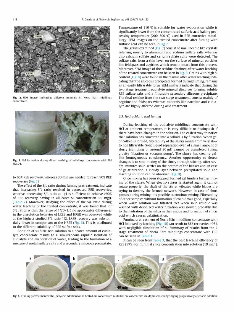
Fig. 2. SEM image indicating different minerals in Norra Karr middlingsconcentrate.
Fig. 3. Gel formation during direct leaching of middlings concentrate with 2MH2SO4.
118 P. Davris et al. /Minerals Engineering 108 (2017) 115–122
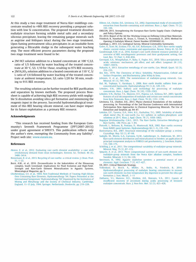
to 65% REE recovery, whereas 30 min are needed to reach 90% REErecoveries (Fig 5).
The effect of the S/L ratio during fuming pretreatment, indicatethat increasing S/L ratio resulted in decreased REE recoveries,whereas decreasing S/L ratio at 1/4 is sufficient to achieve >90%of REE recovery having in all cases Si concentration <30 mg/L(Table 2). Moreover, studying the effect of the S/L ratio duringwater leaching of the treated concentrate, it was found that forS/L ratios within the range of 1/20–1/3 no appreciable differencesin the dissolution behavior of LREE and HREE was observed whileat the highest studied S/L ratio 1/2, LREE recovery was substan-tially lower in comparison to the HREE (Fig. 6). This is attributedto the different solubility of REE sulfate salts.
Addition of sulfuric acid solution to a heated amount of eudia-lyte concentrate results to a simultaneous rapid dissolution ofeudialyte and evaporation of water, leading to the formation of amixture of metal sulfate salts and a secondary siliceous precipitate.
ini�al
a
5 min 4
b
Fig. 4. Fuming pretreatment with H2SO4 acid addition to the heated ore concentrate. (a) I
Temperature of 110 �C is suitable for water evaporation while issignificantly lower from the concentrated sulfuric acid baking pro-cessing temperature (200–500 �C) used in REE extractive metal-lurgy. SEM Images on the treated concentrate after fuming withsulfuric acid can be seen in Fig 7.
The grains examined (Fig. 7) consist of small needle like crystalsreferring mostly to aluminum and sodium sulfate salts whereasalso calcium sulfate and cerium sulfate salts were detected. Thesulfate salts form a thin layer on the surface of mineral particleslike feldspars and aegirine, which remain intact from this process.Moreover, SEM image of the residue obtained after water leachingof the treated concentrate can be seen in Fig. 8. Grains with high Sicontent (Fig. 8) were found in the residue after water leaching indi-cating that the siliceous precipitate formed during fuming, remainsas an easily filtrarable form. SEM analysis indicate that during thetwo stage treatment eudialyte mineral dissolves forming solubleREE sulfate salts and a filtrarable secondary siliceous precipitate.The final residue from the two stage treatment, consist mainly ofaegirine and feldspars whereas minerals like natrolite and eudia-lyte are highly affected during acid treatment.
3.3. Hydrochloric acid fuming
During leaching of the eudialyte middlings concentrate withHCl at ambient temperature, it is very difficult to distinguish ifthere have been changes in the solution. The easiest way to noticethat solution has converted into a colloid is by filtration. When gelor colloid is formed, filterability of the slurry ranges from very slowto non filtrarable. Solid liquid separation even of a small amount ofslurry (sampling of around 20 ml) cannot be completed (usinggravity filtration or vacuum pump). The slurry has creamy gel-like homogeneous consistency. Another opportunity to detectchanges is to stop mixing of the slurry through stirring. After sev-eral minutes solid settles on the bottom of the beaker and, in caseof gelatinization, a cloudy layer between precipitated solid andleaching solution can be observed (Fig. 9).
Once mixing has been stopped, formed gel hinders further mix-ing of the slurry. When electro stirrer is started again it cannotrotate properly, the shaft of the stirrer vibrates while blades aretrying to destroy the formed network. However, in case of shortpauses during mixing it is possible to continue mixing. Filterabilityof other samples without formation of colloid was good, especiallywhen warm solution was filtrated. Yet when solid residue waswashed with deionized water filtration was slower, probably dueto the hydration of the silica in the residue and formation of silicicacid which causes gelatinization.
Fuming pretreatment of Norra Kärr middlings concentrate withHCl followed by leaching (Fig. 10) can result to REE recoveries >95%with negligible dissolution of Si. Summary of results from the 2stage treatment of Norra Kärr middlings concentrate with HClcan be seen in Table 3.
It can be seen from Table 3, that the best leaching efficiency ofREE (97%) for minimal silica concentration into solution (19 mg/l),
0 min 60 min
dc
nitial ore concentrate, (b–d) presents sludge drying progressively after acid addition.
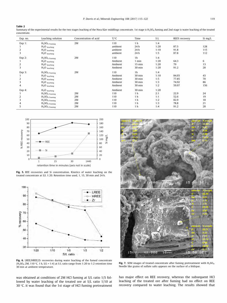
Table 2Summary of the experimental results for the two stages leaching of the Nora Kärr middlings concentrate. 1st stage is H2SO4 fuming and 2nd stage is water leaching of the treatedconcentrate.
Exp. no. Leaching solution Concentration of acid T/�C Time S:L REE% recovery Si mg/L
Exp 1: H2SO4 Fuming 2M 110 1 h 1:41 H2O leaching ambient 24 h 1:20 87.5 1282 H2O leaching ambient 24 h 1:10 91.8 1153 H2O leaching ambient 24 h 1:5 87.8 112
Exp 2: H2SO4 Fuming 2M 110 1h 1:41 H2O leaching Ambient 1 min 1:20 64.3 62 H2O leaching Ambient 15 min 1:20 79 133 H2O leaching Ambient 30 min 1:20 91.2 28
Exp 3: H2SO4 Fuming 2M 110 1h 1:41 H2O leaching Ambient 30 min 1:10 84.03 432 H2O leaching Ambient 30 min 1:5 77.85 703 H2O leaching Ambient 30 min 1:3 74.92 864 H2O leaching Ambient 30 min 1:2 59.97 156
Exp 4: H2O leaching Ambient 30 min 1:201 H2SO4 Fuming 2M 110 1 h 2:1 22.9 242 H2SO4 Fuming 2M 110 1 h 1:1 52.6 193 H2SO4 Fuming 2M 110 1 h 1:2 82.9 184 H2SO4 Fuming 2M 110 1 h 1:3 78.8 215 H2SO4 Fuming 2M 110 1 h 1:4 91.2 28
020406080100120140160180200
0102030405060708090
100
1 15 30 1440
Si m
g/L
% R
EE re
cove
ry
reten�on �me in minutes (axis not in scale)
REE
Si
Fig. 5. REE recoveries and Si concentration. Kinetics of water leaching on thetreated concentrate at S/L 1:20. Retention time used, 1, 15, 30 min and 24 h.
Fig. 6. LREE/HREE/Zr recoveries during water leaching of the fumed concentrate(H2SO4 2M, 110 �C, 1 h, S/L = 1:4) at S:L ratio range from 1:20 to 1:2 retention time30 min at ambient temperature.
element % weightO 61.35Na 4.55Al 3.50Si 2.86S 20.25Ca 1.56Ce 6.42
element % weightO 50.71Na 0.16Al 7.68Si 29.23S 0.89K 10.93Ca 0.13
element % weightO 68.43Na 4.30Al 4.39Si 0.89S 21.25Mn 0.75
element % weightO 68.43Na 4.30Al 4.39Si 0.89S 21.25Mn 0.75
Fig. 7. SEM images of treated concentrate after fuming pretreatment with H2SO4.Needle like grains of sulfate salts appears on the surface of a feldspar.
P. Davris et al. /Minerals Engineering 108 (2017) 115–122 119
was obtained at conditions of 2M HCl fuming at S/L ratio 1/5 fol-lowed by water leaching of the treated ore at S/L ratio 1/10 at30 �C. it was found that the 1st stage of HCl fuming pretreatment
has major effect on REE recovery, whereas the subsequent HClleaching of the treated ore after fuming had no effect on REErecovery compared to water leaching. The results showed that
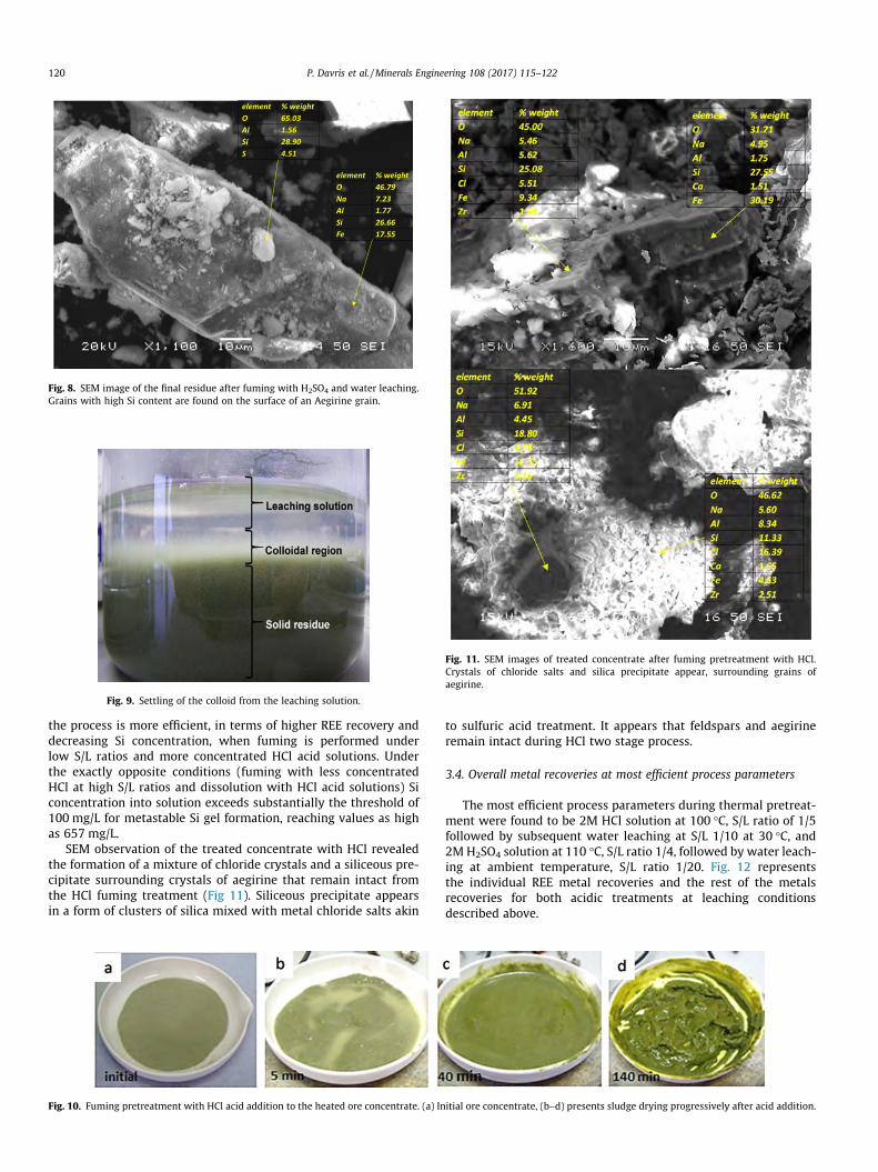
Fig. 9. Settling of the colloid from the leaching solution.
element % weightO 65.03Al 1.56Si 28.90S 4.51
element % weightO 46.79Na 7.23Al 1.77Si 26.66Fe 17.55
Fig. 8. SEM image of the final residue after fuming with H2SO4 and water leaching.Grains with high Si content are found on the surface of an Aegirine grain.
Fig. 11. SEM images of treated concentrate after fuming pretreatment with HCl.Crystals of chloride salts and silica precipitate appear, surrounding grains ofaegirine.
120 P. Davris et al. /Minerals Engineering 108 (2017) 115–122
the process is more efficient, in terms of higher REE recovery anddecreasing Si concentration, when fuming is performed underlow S/L ratios and more concentrated HCl acid solutions. Underthe exactly opposite conditions (fuming with less concentratedHCl at high S/L ratios and dissolution with HCl acid solutions) Siconcentration into solution exceeds substantially the threshold of100 mg/L for metastable Si gel formation, reaching values as highas 657 mg/L.
SEM observation of the treated concentrate with HCl revealedthe formation of a mixture of chloride crystals and a siliceous pre-cipitate surrounding crystals of aegirine that remain intact fromthe HCl fuming treatment (Fig 11). Siliceous precipitate appearsin a form of clusters of silica mixed with metal chloride salts akin
Fig. 10. Fuming pretreatment with HCl acid addition to the heated ore concentrate. (a) In
to sulfuric acid treatment. It appears that feldspars and aegirineremain intact during HCl two stage process.
3.4. Overall metal recoveries at most efficient process parameters
The most efficient process parameters during thermal pretreat-ment were found to be 2M HCl solution at 100 �C, S/L ratio of 1/5followed by subsequent water leaching at S/L 1/10 at 30 �C, and2MH2SO4 solution at 110 �C, S/L ratio 1/4, followed by water leach-ing at ambient temperature, S/L ratio 1/20. Fig. 12 representsthe individual REE metal recoveries and the rest of the metalsrecoveries for both acidic treatments at leaching conditionsdescribed above.
itial ore concentrate, (b–d) presents sludge drying progressively after acid addition.

Table 3Summary of the experiments and factors studied on two stage leaching of Nora Kärr middlings concentrate with HCl. 1st stage is HCl fuming and 2nd stage is water/acid leachingof the treated concentrate.
Exp. no. Leaching solution Concentration of acid T/�C Time (h) S:L REE% recovery Si mg/L
Exp1: HCl Fuming 2M 100 1 1:51 H2O leaching 30 1 1:10 97.12 192 HCl leaching 1M 30 1 1:10 92.45 223 HCl leaching 2M 30 1 1:10 87.66 42
Exp2: HCl Fuming 1M 100 1 1:51 H2O leaching 30 1 1:10 51.96 42 HCl leaching 1M 30 1 1:10 55.68 533 HCl leach 2M 30 1 1:10 54.62 66
Exp3: HCl Fuming 2M 100 1 1:21 H2O leaching 30 1 1:10 58.55 72 HCl leaching 1M 30 1 1:10 58.02 603 HCl leaching 2M 30 1 1:10 65.03 95
Exp4: HCl Fuming 1M 100 1 1:21 H2O leaching 30 1 1:10 13.07 132 HCl leaching 1M 30 1 1:10 14.34 3673 HCl leaching 2M 30 1 1:10 19.23 657
0
20
40
60
80
100
La Ce Pr Nd
Sm Eu Gd Tb Dy Ho Er Tm Yb Lu YTR
EE Si Al Fe Ca Mg Na Zr
% re
cove
ry
HCl
H2SO4
Fig. 12. Individual metal recoveries from NKA C middlings ore concentrate. HCl route: Fuming at S/L 1/5 then water leaching at S/L 1/10 at 30 �C. H2SO4 route: Fuming at S/L1/4 then water leaching at ambient temperature at S/L 1/20 for 30 min.
100-110 0C Fuming
Middlings ore concentrate
Treated concentrate
Leaching
Mixed slurry
to REE purification and separation
Solution enriched in REE
solid residue
water
2M HCl orH2SO4 dropwise
added
SL
Heat
Fig. 13. Conceptual flowsheet of the two stage treatment of Eudialyte concentratefor REE recovery.
P. Davris et al. /Minerals Engineering 108 (2017) 115–122 121
Si recovery was found to be negligible whereas moderate recov-eries obtained for the rest of the metals (Fig 12). The two stagetreatment can be applied using either using sulfuric or hydrochlo-ric acid resulting to almost similar metal recoveries. Particularly Zrfound to have higher recovery yield in H2SO4 treatment compare toHCl. Most of the metal impurities originate from eudialyte andnatrolite minerals dissolution that are present in the middlingsore concentrate. The resulting final leachate obtained after waterleaching of the treated concentrate had a pH value of 0.8–1 andcan be further treated for REE purification. Acid addition onleaching conditions that provide the highest REE recovery foundto be 0.98 g HCl (37%w/w) or 0.81 g H2SO4 (95–98%w/w) per g ofmiddlings ore concentrate.
Compared to direct leaching, advantages of fuming withacid are high REE recovery rate, no silica gel formation and noadditional additives for suppressing silica gel. Moreover, in con-trast to sulfuric acid, hydrochloric acid can be easily recovered,especially during the fuming treatment, where it can be collecteddirectly after evaporation. On the other hand, such a two stageprocess is complicated and more sophisticated, acid corrosionresistant equipment is required. According to the proposed twostage treatment the following conceptual flowsheet on Eudialytehydrometallurgical processing is developed (Fig. 13).
4. Conclusion
Leaching REE from eudialyte mineral by suppressing silica gelformation is crucial for its effective hydrometallurgical treatment.
122 P. Davris et al. /Minerals Engineering 108 (2017) 115–122
At this study a two stage treatment of Norra Kärr middlings con-centrate resulted to >90% REE recovery providing a pregnant solu-tion with low Si concentration. The proposed treatment dissolveseudialyte structure forming soluble metal salts and a secondarysiliceous precipitate, leaving the remaining gangue minerals suchas aegirine and feldspars intact during the two stage treatment.Upon fuming pretreatment silica precipitates in an insoluble formgenerating a filtrarable sludge in the subsequent water leachingstep. The most efficient process parameters during the proposedtwo stage treatment were found to be:
� 2M HCl solution addition to a heated concentrate at 100 �C,S/Lratio of 1/5 followed by water leaching of the treated concen-trate at 30 �C, S/L 1/10 for 1hour, resulting to 97% REE recovery.
� 2MH2SO4 solution addition to a heated concentrate at 110 �C, S/L ratio of 1/4 followed by water leaching of the treated concen-trate at ambient temperature, S/L ratio 1/20 for 30 min, result-ing to 91% REE recovery.
The resulting solution can be further treated for REE purificationand separation by known methods. The proposed process flow-sheet is capable of achieving high REE recovery yields with negligi-ble Si dissolution avoiding silica gel formation and minimizing thereagents input in the process. Successful hydrometallurgical treat-ment of this REE bearing silicate mineral, can have major impactfor its future exploitation as a primary REE resource.
Acknowledgments
‘‘This research has received funding from the European Com-munity’s Seventh Framework Programme ([FP7/2007-2013])under grant agreement n�309373. This publication reflects onlythe author’s view, exempting the Community from any liability”.Project web site: www.eurare.eu.
References
Alonso, E. et al., 2012. Evaluating rare earth element availability: a case withrevolutionary demand from clean technologies. Environ. Sci. Technol. 46 (6),3406–3414.
Binnemans, K. et al., 2013. Recycling of rare earths: a critical review. J. Clean. Prod.51, 1–22.
Borst, A.M., et al., 2016. Zirconosilicates in the kakortokites of the Ilímaussaqcomplex, South Greenland: Implications for Fluid Evolution and High-Field-Strength and Rare-Earth Element Mineralization in Agpaitic Systems,Mineralogical Magazine, pp. 5.
Chizhevskaya, S.V. et al., 1994. Non-Traditional Methods of Treating High-SiliconOres Containing Rare Elements, Hydrometallurgy ’94: Papers Presented at theInternational Symposium ‘Hydrometallurgy ’94’ Organized by the Institution ofMining and Metallurgy and the Society of Chemical Industry, Cambridge,England, 11–15 July, 1994. Springer, Netherlands, Dordrecht, pp. 219–228.
Dibrov, I.A., Chirkst, D.E., Litvinova, T.E., 2002. Experimental study of zirconium(IV)extraction from fluoride-containing acid solutions. Russ. J. Appl. Chem. 75 (2),195–199.
ERECON, 2015. Strengthening the European Rare Earths Supply Chain: Challengesand Policy Options.
EU, 2014. Report of the Ad Hoc Working Group on Defining Critical Raw Materials.Friedrich, B., Hanebuth, M., Kruse, S., Tremel, A., Vossenkaul, D., 2016. Method for
Opening A Eudialyte Mineral. Patent Number EP2995692 A1.Gambogi, J., 2015. U.S. Geological Survey, Mineral Commodity Summaries.Golev, A., Scott, M., Erskine, P.D., Ali, S.H., Ballantyne, G.R., 2014. Rare earths supply
chains: current status, constraints and opportunities. Resour. Policy 41, 52–59.Goodenough, K.M. et al., 2016. Europe’s rare earth element resource potential: an
overview of REE metallogenetic provinces and their geodynamic setting. OreGeol. Rev. 72 (Part 1), 838–856.
Gorrepati, E.A., Wongthahan, P., Raha, S., Fogler, H.S., 2010. Silica precipitation inacidic solutions: mechanism, pH effect, and salt effect. Langmuir 26 (13),10467–10474.
Habashi, F., 2013. Extractive metallurgy of rare earths. Can. Metall. Quart. 52 (3),224–233.
Iler, R.K., 1979. The Chemistry of Silica: Solubility, Polymerization, Colloid andSurface Properties, and Biochemistry. John Wiley & Sons.
Johnsen, O. et al., 2003. The nomenclature of eudialyte-group minerals. Can.Mineral. 41 (3), 785–794.
Kul, M., Topkaya, Y., Karakaya, _I., 2008. Rare earth double sulfates from pre-concentrated bastnasite. Hydrometallurgy 93 (3–4), 129–135.
Lebedev, V.N., 2003. Sulfuric acid technology for processing of eudialyteconcentrate. Russ. J. Appl. Chem. 76 (10), 1559–1563.
Lebedev, V.N., Shchur, T.E., Maiorov, D.V., Popova, L.A., Serkova, R.P., 2003. Specificfeatures of acid decomposition of eudialyte and certain rare-metal concentratesfrom Kola Peninsula. Russ. J. Appl. Chem. 76 (8), 1191–1196.
Litvinova, T.E., Chirkist, D.E., 2013. Physic-chemical foundations of the eudialyteprocessing. In: Proceedings of the 2nd Russian Conference with InternationalParticipation New Approaches to Chemical Engineering Minerals. The Use ofExtraction and Sorption, pp. 84–87.
Lokshin, E.P., Tareeva, O.A., Ivlev, K.G., Kashulina, T.G., 2005. Solubility of doublealkali metal (Na, K) rare-earth (La, Ce) sulfates in sulfuric-phosphoric acidsolutions at 20 �C. Russ. J. Appl. Chem. 78 (7), 1058–1063.
Nagaiyar Krishnamurthy, C.K.G., 2015. The Rare Earths, Extractive Metallurgy ofRare Earths. CRC Press, pp. 1–84.
Pietrelli, L., Bellomo, B., Fontana, D., Montereali, M.R., 2002. Rare earths recoveryfrom NiMH spent batteries. Hydrometallurgy 66 (1–3), 135–139.
Rastsvetaeva, R.K., 2007. Structural mineralogy of the eudialyte group: a review.Crystallogr. Rep. 52 (1), 47–64.
Sadeghi, M., Morris, G.A., Carranza, E.J.M., Ladenberger, A., Andersson, M., 2013.Rare earth element distribution and mineralization in Sweden: an application ofprincipal component analysis to FOREGS soil geochemistry. J. Geochem. Explor.133, 160–175.
Schilling, J. et al., 2011. The compositional variability of eudialyte-group minerals.Mineral. Mag. 75 (1), 87–115.
Sjöqvist, A. et al., 2013. Three compositional varieties of rare-earth element ore:eudialyte-group minerals from the Norra Kärr alkaline complex, SouthernSweden. Minerals 3 (1), 94–120.
Sørrensen, H., 1992. Agpaitic nepheline syenites: a potential source of rareelements. Appl. Geochem. 7 (5), 417–427.
US, 2011. Critical Materials Strategy.Voßenkaul, D., Birich, A., Müller, N., Stoltz, N., Friedrich, B., 2016.
Hydrometallurgical processing of eudialyte bearing concentrates to recoverrare earth elements via low-temperature dry digestion to prevent the silica gelformation. J. Sust. Metall., 1–11
Zakharov, V.I., Maiorov, D.V., Alishkin, A.R., Matveev, V.A., 2011. Causes ofinsufficient recovery of zirconium during acidic processing of lovozeroeudialyte concentrate. Russ. J. Non-Ferr. Met. 52 (5), 423–428.