LCS COMPLETE Knee Systemsynthes.vo.llnwd.net › o16 › LLNWMB8 › US Mobile › Synthes...
42
LCS COMPLETE ™ Knee System High Performance Instruments Surgical Technique
Transcript of LCS COMPLETE Knee Systemsynthes.vo.llnwd.net › o16 › LLNWMB8 › US Mobile › Synthes...

LCS COMPLETE™ Knee SystemHigh Performance Instruments
Surgical Technique

SURGICALTECHNIQUE
This surgical technique provides instruction on the implantation of the LCS COMPLETE™ Knee System family of knee implants.
There are several approach options available to the surgeon, the most common are: medial parapatellar, mini-midvastus and mini-subvastus.

Table of Contents
Surgical Technique LCS COMPLETE™ Knee System DePuy Synthes 1
Surgical Technique Surgical Summary 2
Incision and Exposure 4
Patella Resection 7
Tibial Jig Assembly 9
Lower Leg Alignment 10
Tibial Resection 12
Femoral Sizing 13
Intramedullary (I.M) Hole Preparation 14
Long Leg Alignment (Optional Simulated Distal Cut) 15
Anterior/Posterior (A/P) Block Assembly 16
Femoral Rotation 17
A/P Resection 18
Flexion Gap Assessment 19
Distal Femoral Alignment 20
Distal Cutting Block Assembly 21
Distal Cutting Block and Valgus Assessment 22
Extension Gap Assessment and Distal Femoral Resection 23
Final Femoral Preparation 24
Tibial Preparation 25
Tibial Preparation - MBT 26
Trial Reduction 27
Patella Preparation 28
Cementing Technique 29
Final Component Implantation 30
Closure 31
Appendix A: Tibial I.M. Jig Alignment 32
Appendix B: Spiked Uprod 35
Appendix C: Posterior Stabilized (PS) Final Femoral Preparation 38
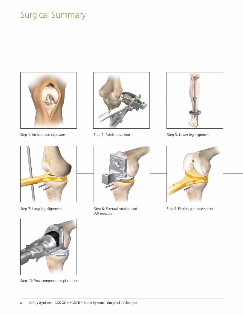
Step 8: Femoral rotation and A/P resection
Step 2: Patella resection
Step 9: Flexion gap assessment
Step 3: Lower leg alignmentStep 1: Incision and exposure
Step 7: Long leg alignment
Step 13: Final component implantation
2 DePuy Synthes LCS COMPLETE™ Knee System Surgical Technique
Surgical Summary

Step 10: Distal femoral resection
Step 4: Tibial resection
Step 11: Final femoral preparation
Step 5: Femoral sizing
Step 12: Trial reduction
Step 6: I.M. hole preparation
Surgical Technique LCS COMPLETE™ Knee System DePuy Synthes 3
Surgical Summary

The LCS COMPLETE Knee System High Performance Instrumentation is designed for use with and without DePuy Synthes Companies of Johnson & Johnson own CAS (Computer Assisted Surgery) System, for both open and less invasive approaches to the knee.
Make a straight midline skin incision starting from 2 to 4 cm above the patella, passing over the patella, and ending at the tibial tubercle (Figure 1).
The three most common approach options for the surgeon are: medial parapatellar, mini-midvastus and mini-subvastus.
For surgeons choosing the medial parapatellar (Figure 2): Make a medial parapatellar incision through the retinaculum, the capsule and the synovium, with neutral alignment or with varus deformity. The medial parapatellar incision starts proximal (4 cm) to the patella, incising the rectus femoris tendon longitudinally, and continues distally around the medial aspect of the patella and ligamentum patella stopping just medial to the tibial tubercle (Figure 2). Following this incision, evert the patella laterally to expose the entire tibio-femoral joint.
Figure 2
Figure 1
4 DePuy Synthes LCS COMPLETE™ Knee System Surgical Technique
Incision and Exposure

For surgeons choosing the mini-midvastus option (Figure 3): The midvastus approach starts 3-4 cm in the middle of the Vastus Medialis Obliquus (VMO), running distal and lateral to the muscle fibers towards the rectus femoris, splitting the VMO.
Continue the incision distally around the medial aspect of the patella and ligamentum patella stopping just medial to the tibial tubercle (Figure 3). Following this incision, evert the patella laterally to expose the entire tibio-femoral joint.
For surgeons choosing the subvastus option (Figure 4): The subvastus approach starts by lifting the VMO with a 90 degree stomp hook. A 3-4 cm incision is made in the capsule underneath the VMO, running horizontal from medial to lateral towards the mid-portion of the patella. The incision continues distally around the medial aspect of the patella and ligamentum patella stopping just medial to the tibial tubercle. Following this incision, evert the patella laterally to expose the entire tibio-femoral joint.
Figure 3
Figure 4
Surgical Technique LCS COMPLETE™ Knee System DePuy Synthes 5
Incision and Exposure

Figure 5
Excise hypertrophic synovium if present and a portion of the infrapatella fat pad to allow access to the medial, lateral and intercondylar spaces.
Remove all osteophytes at this stage as they can affect soft tissue balancing (Figure 5).
Note: Particular attention should be given to posterior osteophytes as they may affect flexion contracture or femoral rotation.
6 DePuy Synthes LCS COMPLETE™ Knee System Surgical Technique
Incision and Exposure

13-15 mm
Bone resection
Posterior
Anterior
Example: for a standard patella
25 mm thick, resect 11.6 mm of
articular surface, leaving 13.4 mm
of residual bone to accommodate
the 10.9 mm thickness implant.
Figure 8 Figure 9
Size Lg+ - resects 13 mm
Sizes Sm/Sm+/Med - resects 10 mm
Sizes Std/Std+/Lg - resects 11.6 mm
Figure 7
Warning: When using the LCS COMPLETE RPS Knee System, the patella must be resurfaced. Failure to resurface the patella has been associated with a higher incidence of postoperative patello-femoral pain potentially leading to a secondary procedure.
Resection and preparation of the patella can be performed sequentially or separately, as desired, and can be performed at any time during surgery.
Determine the thickness of the patella and calculate the level of bone resection (Figure 6). The thickness of the resurfaced patella should be the same as the natural patella. There should be equal amounts of bone remaining in the medial/lateral and superior/ inferior portions of the patella.
Select a patella stylus that matches the thickness of the implant to be used. Slide the appropriate size stylus into the saw capture of the resection guide. The minimum depth of the patella resection should be no less than 10 mm (Figure 7).
However, when the patella is small, a minimal residual thickness of 12 mm should be maintained to avoid fracture.
A 12 mm remnant stylus can be attached to the resection guide resting on the anterior surface of the patella, to avoid over resection (Figure 8).
Place the leg in extension and evert the patella. Next position the patella resection guide with the sizing stylus against the posterior cortex of the patella with the serrated jaws at the superior and inferior margins of the articular surface. Close the jaws to firmly engage the patella (Figure 9).
Figure 6
Surgical Technique LCS COMPLETE™ Knee System DePuy Synthes 7
Patella Resection

Remove the stylus and perform the resection using an oscillating saw through the saw capture and flush to the cutting surface (Figure 10).
A patella wafer can be hand placed on the resected surface if required to protect the patella bone bed.
Figure 10
Patella wafer
8 DePuy Synthes LCS COMPLETE™ Knee System Surgical Technique
Patella Resection

Tibial jig uprod
Figure 11
Tibial cutting blocks(Left/Right 7 degree)
Press down to attach cutting block
The tibia can now be resected to create more room in the joint space.
Assemble the appropriate 7 degree, left/right or symmetrical cutting block to the tibial jig uprod. Slide the tibial jig uprod into the ankle clamp assembly (Figure 11).
Note: For tibial resection using intramedullary alignment, see Appendix A. For tibial resection using a spiked uprod, see Appendix B.
Surgical Technique LCS COMPLETE™ Knee System DePuy Synthes 9
Tibial Jig Assembly

Figure 13
Center of the tibial adapter
Place the knee in 90 degrees of flexion with the tibia translated anteriorly and stabilized. Place the ankle clamp proximal to the malleoli (Figure 12). Align the proximal central marking on the tibia cutting block with the medial one third of the tibial tubercle to set rotation (Figure 13). To provide stability, insert a central pin through the vertical slot in the cutting block (Figure 14). Push the quick release button to set the approximate resection level (Figure 15).
Varus/Valgus
Align the tibial jig ankle clamp parallel to the transmalleolar axis to establish rotational alignment (Figure 14). The midline of the tibia is approximately 3 mm medial to the transaxial midline. Translate the lower assembly medially (usually to the second vertical mark), by pushing the varus/valgus adjustment wings (Figure 14). There are vertical scribe marks for reference aligning to the middle of the talus.
Slope
The tibial jig uprod and ankle clamp are designed to prevent an adverse anterior slope. On an average size tibia this guide gives approximately a 7 degree (Figure 16) tibial slope when the slope adjustment is translated anteriorly until it hits the stop.
Note: This may not give a true 7 degree slope.
Figure 15
Quick release button
Figure 12
Vertical pin slot
Varus/valgus wings
Figure 14
11 DePuy Synthes LCS COMPLETE™ Knee System Surgical Technique
Lower Leg Alignment
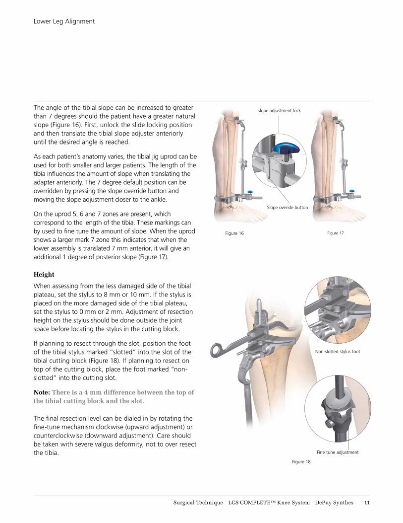
Figure 18
Figure 16 Figure 17
Fine tune adjustment
Slope overide button
Non-slotted stylus foot
Slope adjustment lockThe angle of the tibial slope can be increased to greater than 7 degrees should the patient have a greater natural slope (Figure 16). First, unlock the slide locking position and then translate the tibial slope adjuster anteriorly until the desired angle is reached.
As each patient’s anatomy varies, the tibial jig uprod can be used for both smaller and larger patients. The length of the tibia influences the amount of slope when translating the adapter anteriorly. The 7 degree default position can be overridden by pressing the slope override button and moving the slope adjustment closer to the ankle.
On the uprod 5, 6 and 7 zones are present, which correspond to the length of the tibia. These markings can by used to fine tune the amount of slope. When the uprod shows a larger mark 7 zone this indicates that when the lower assembly is translated 7 mm anterior, it will give an additional 1 degree of posterior slope (Figure 17).
Height
When assessing from the less damaged side of the tibial plateau, set the stylus to 8 mm or 10 mm. If the stylus is placed on the more damaged side of the tibial plateau, set the stylus to 0 mm or 2 mm. Adjustment of resection height on the stylus should be done outside the joint space before locating the stylus in the cutting block.
If planning to resect through the slot, position the foot of the tibial stylus marked “slotted” into the slot of the tibial cutting block (Figure 18). If planning to resect on top of the cutting block, place the foot marked “non-slotted” into the cutting slot.
Note: There is a 4 mm difference between the top of the tibial cutting block and the slot.
The final resection level can be dialed in by rotating the fine-tune mechanism clockwise (upward adjustment) or counterclockwise (downward adjustment). Care should be taken with severe valgus deformity, not to over resect the tibia.
Surgical Technique LCS COMPLETE™ Knee System DePuy Synthes 11
Lower Leg Alignment

After the height has been set, pin the block through the 0 mm set of holes (the stylus may need to be removed for access). +/-2 mm pinholes are available on the resection blocks to further adjust the resection level where needed.
The block can be securely fixed with a convergent pin. Resect the tibia using a 1.47 mm saw blade (Figure 19) and remove the resected bone.
Remove the central pin from the slot and divergent locking pin if used. The remaining tibial pins may be left in place to aid alignment during the procedure.
Check the depth and accuracy of the bone cut before removing the tibial cutting block. A 2 degree varus/valgus recut block is available if required.
Figure 19
12 DePuy Synthes LCS COMPLETE™ Knee System Surgical Technique
Tibial Resection
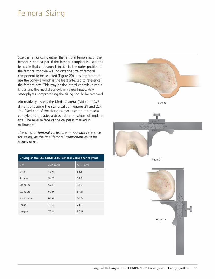
Figure 20
Figure 21
Figure 22
Size the femur using either the femoral templates or the femoral sizing caliper. If the femoral template is used, the template that corresponds in size to the outer profile of the femoral condyle will indicate the size of femoral component to be selected (Figure 20). It is important to use the condyle which is the least affected to reference the femoral size. This may be the lateral condyle in varus knees and the medial condyle in valgus knees. Any osteophytes compromising the sizing should be removed.
Alternatively, assess the Medial/Lateral (M/L) and A/P dimensions using the sizing caliper (Figures 21 and 22). The fixed end of the sizing caliper rests on the medial condyle and provides a direct determination of implant size. The reverse face of the caliper is marked in millimeters.
The anterior femoral cortex is an important reference for sizing, as the final femoral component must be seated here.
Driving of the LCS COMPLETE Femoral Components (mm)
Size A/P (mm) M/L (mm)
Small 49.6 53.8
Small+ 54.7 59.2
Medium 57.8 61.9
Standard 60.9 64.6
Standard+ 65.4 69.6
Large 70.4 74.9
Large+ 75.8 80.6
Surgical Technique LCS COMPLETE™ Knee System DePuy Synthes 13
Femoral Sizing

Depress the sizing button and slide the I.M. hole locator until the chosen femoral size appears directly above the line. Position the yoke beneath the muscle anteriorly, on the periosteum, and center the device on the anterior femoral shaft (Figure 23).
An extramedullary (EM) alignment rod can be placed through the handle of the I.M. hole locator to aid alignment.
Carefully position the I.M. hole locator between the epicondyles. The position of the femoral I.M. hole is generally 3-5 mm medial to the apex of the intercondylar notch and 7-10 mm anterior to the origin of the PCL. Drawing a centering mark or Whiteside’s Line and the pre-operative X-ray may be useful to assist precise location of the I.M. hole (Figure 24).
At this moment the ultimate rotational position of the femoral implant is not yet defined. Pins can be placed in the I.M. hole locator to assist with additional stability. The device may also be lightly impacted onto the distal femur for additional stability.
Open up the I.M. canal on the distal femur using the 9 mm I.M. starter drill (Figure 25).
Take care to ensure that the drill avoids the cortices. The drill may be toggled slightly to prevent over-pressurization of the I.M. canal.
Excessive toggling may result in an overly wide I.M. hole and should be avoided.
Remove the pins, then the I.M. hole locator and clear the canal of fat and fluid.
Figure 25
Whiteside’s line
I.M. hole location
Sizing button
Femoral size
selected line
Sm/Sm+
Med/Std+
Lg/Lg+
Figure 24
Figure 23
14 DePuy Synthes LCS COMPLETE™ Knee System Surgical Technique
I.M. Hole Preparation

Select the appropriate I.M. plate (3-8 degree angle) as determined during pre-operative X-ray analysis. Insert the I.M. plate into the distal femoral I.M. canal taking care to avoid over-pressurization (Figure 26).
Place the knee in full extension. Insert a 10 mm spacer block onto the I.M. plate and into the extension space to assess alignment (Figure 27). If the extension gap is too small for the standard 10 mm block, the 4 mm spacer block can be used.
The surgeon should be aware that the I.M. canal is providing an approximation of the correct anatomic axis.
The extension gap must be rectangular in configuration with the leg in full extension. If the gap is not rectangular, the extension gap is not balanced and appropriate soft tissue balancing must be performed.
Equal medial and lateral lift-off should not exceed 3-5 mm. This is visually assessed by judging the position of the I.M. plate relative to the tibial resection.
The extramedullary alignment rod attached through the spacer block handle may be helpful in assessing alignment (Figure 28). If the extension gap is too small for the standard 10 mm block, the 4 mm spacer block can be used. The most common cause for a tight extension gap is the presence of a fixed flexion contracture. This may be caused by posterior femoral osteophytes or a contracture of the capsule itself. In this case, removal of the osteophytes or release of the capsule may be indicated.
Figure 28
Figure 26
Figure 27
Surgical Technique LCS COMPLETE™ Knee System DePuy Synthes 15
Long Leg Alignment (Optional Simulated Distal Cut)
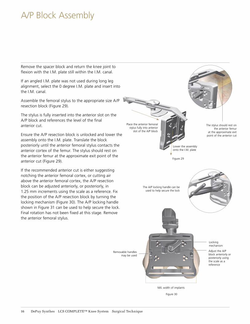
Figure 29
Remove the spacer block and return the knee joint to flexion with the I.M. plate still within the I.M. canal.
If an angled I.M. plate was not used during long leg alignment, select the 0 degree I.M. plate and insert into the I.M. canal.
Assemble the femoral stylus to the appropriate size A/P resection block (Figure 29).
The stylus is fully inserted into the anterior slot on the A/P block and references the level of the final anterior cut.
Ensure the A/P resection block is unlocked and lower the assembly onto the I.M. plate. Translate the block posteriorly until the anterior femoral stylus contacts the anterior cortex of the femur. The stylus should rest on the anterior femur at the approximate exit point of the anterior cut (Figure 29).
If the recommended anterior cut is either suggesting notching the anterior femoral cortex, or cutting air above the anterior femoral cortex, the A/P resection block can be adjusted anteriorly, or posteriorly, in 1.25 mm increments using the scale as a reference. Fix the position of the A/P resection block by turning the locking mechanism (Figure 30). The A/P locking handle shown in Figure 31 can be used to help secure the lock. Final rotation has not been fixed at this stage. Remove the anterior femoral stylus.
Figure 30
Place the anterior femoral stylus fully into anterior
slot of the A/P block
The A/P locking handle can be used to help secure the lock
Lower the assembly onto the I.M. plate
The stylus should rest on the anterior femur
at the approximate exit point of the anterior cut
Removable handles may be used
Locking mechanism
M/L width of implants
Adjust the A/P block anteriorly or posteriorly using the scale as a reference
16 DePuy Synthes LCS COMPLETE™ Knee System Surgical Technique
A/P Block Assembly

Figure 32
Figure 31
Introduce the femoral guide positioner into the joint space engaging the middle slot of the A/P resection block (Figure 31). The knee may be slightly flexed or extended until the positioner lies flat on the previously resected proximal tibia.
If the collateral ligaments are balanced and the joint space is too tight to accept the femoral guide positioner, the tibial cut and chosen A/P size may need to be reviewed. If too tight, the tibial cutting block can be placed back onto the tibial fixation pins, selecting a more proximal row of holes, lowering the block and resecting additional proximal tibial bone.
If the joint space is too lax, tibial shims may be added to ensure that the positioner fits snugly (Figure 32). If tibial shims greater than 15 mm are required to remove the laxity in flexion, the A/P sizing may need to be re-evaluated. If required, the femoral component may be upsized or downsized at this stage, by selecting the next sized A/P resection block and sliding it onto the I.M. plate.
The A/P femoral resection blocks are anterior-referencing (i.e. the same distance from the anterior cutting surface regardless of component size) so any additional resection will remove bone from the posterior condyles.
12.5 mm
Tibial Shims
15 mm
17.5 mm
20 mm
Surgical Technique LCS COMPLETE™ Knee System DePuy Synthes 17
Femoral Rotation

Figure 33
Note that down sizing by one size will result in approximately 5 mm more bone being removed from the posterior condyles, effectively increasing the flexion gap by 5 mm. Re-evalute the tibial alignment using the external alignment rod, passed through the hole in the femoral guide positioner (Figure 33).
The femoral rotation is set by the femoral guide positioner and is based on the principle of equal compartment tension and balanced collateral ligaments. Using the femoral guide positioner, this balance should automatically occur because the femur can freely rotate around the I.M. plate.
Rotation is correct when the collateral ligaments are tensioned and balanced. Conduct a final check of the anterior resection level with the visualization wing. All adjustments should be made prior to pinning the block. Pin the A/P resection block to the distal femur using the two neutral central holes (marked with a square) before cutting.
Remove the femoral guide positioner. Resect the anterior cortex through the slots using a 1.47 mm saw blade (Figure 34) and remove the resected bone. The final size of the femoral component can be checked and changed if necessary. The posterior femoral condyles are then resected.
Figure 34
18 DePuy Synthes LCS COMPLETE™ Knee System Surgical Technique
A/P Resection

Figure 35
Figure 36
Once the resections are completed, remove the pins, cutting block and I.M. plate.
To determine the flexion gap, insert the spacer block assembly into the flexion gap.
The assembly consists of a 10 mm base handle (equivalent to the final tibial baseplate and tibial insert thickness) plus a femoral shim (equivalent to the thickness of the femoral condyle on the implant) (Figure 35).
Assess medial and lateral tension, as the compartments should be equal. If necessary, a tibial shim may be added to the spacer block (Figure 36).
Make a note of the thickness of the spacer block utilized for the flexion gap. This will subsequently determine the extension gap.
Surgical Technique LCS COMPLETE™ Knee System DePuy Synthes 19
Flexion Gap Assessment
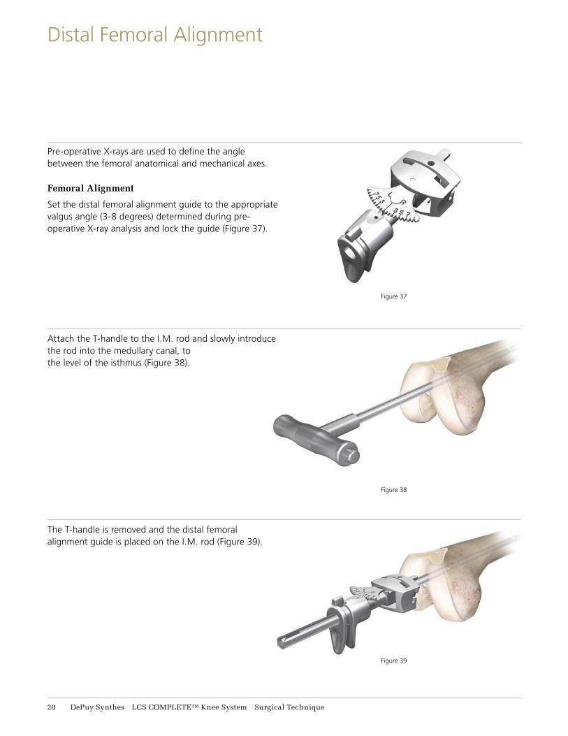
Figure 38
Figure 37
Figure 39
Pre-operative X-rays are used to define the angle between the femoral anatomical and mechanical axes.
Femoral Alignment
Set the distal femoral alignment guide to the appropriate valgus angle (3-8 degrees) determined during pre-operative X-ray analysis and lock the guide (Figure 37).
Attach the T-handle to the I.M. rod and slowly introduce the rod into the medullary canal, to the level of the isthmus (Figure 38).
The T-handle is removed and the distal femoral alignment guide is placed on the I.M. rod (Figure 39).
21 DePuy Synthes LCS COMPLETE™ Knee System Surgical Technique
Distal Femoral Alignment

Figure 42
Figure 41
The distal femoral outrigger and distal cutting block are assembled and then lowered down through the distal femoral alignment guide (Figures 40, 41 and 42).
The distal cutting block must have the pop-up saw capture open to assemble onto the distal femoral outrigger. The pop-up saw capture can be opened by inserting a sawblade into the slot.
The distal femoral alignment guide should be placed into the notch of the femur.
It is important that the body of the distal cutting block remains flush on the anterior femoral cut (Figure 42).
Figure 40
Pull together to connect cutting block
Pop-up saw capture in open position
Surgical Technique LCS COMPLETE™ Knee System DePuy Synthes 21
Distal Cutting Block Assembly
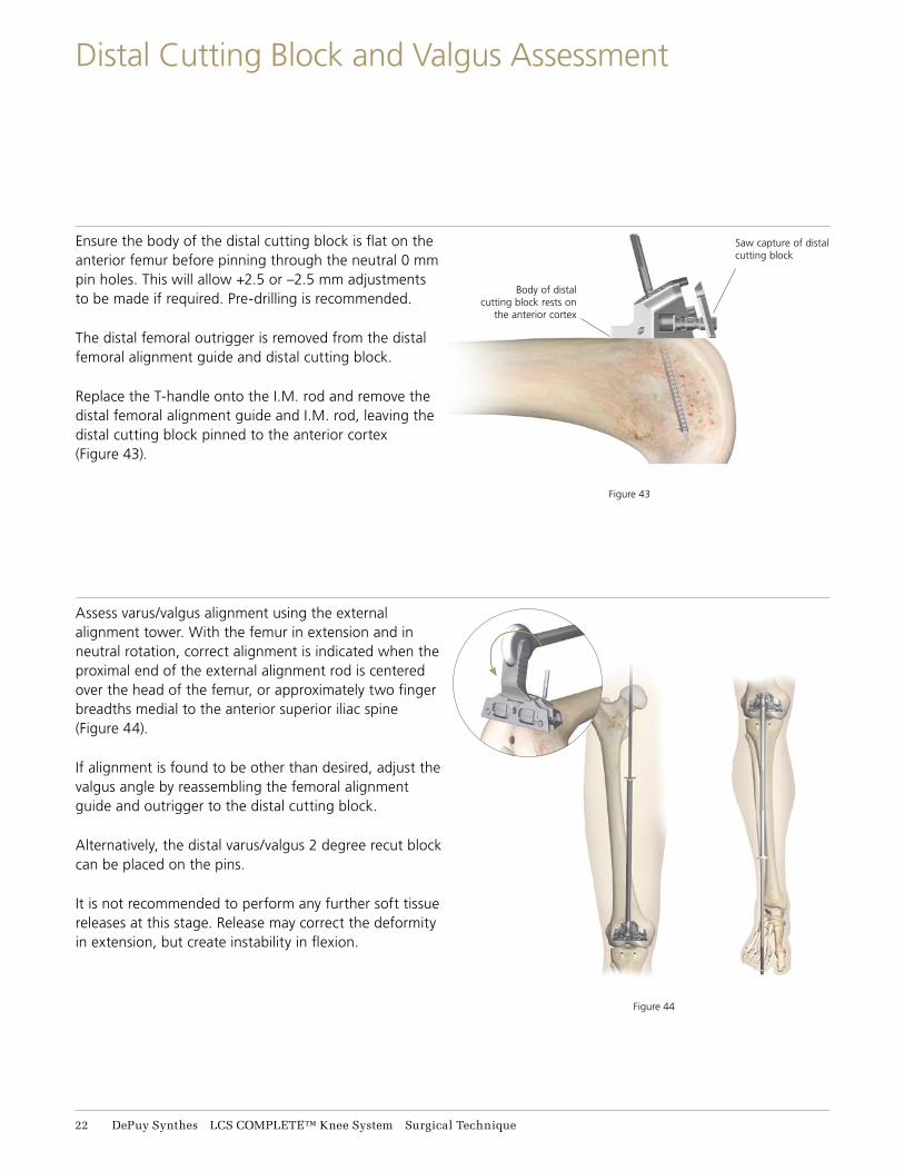
Figure 43
Figure 44
Ensure the body of the distal cutting block is flat on the anterior femur before pinning through the neutral 0 mm pin holes. This will allow +2.5 or –2.5 mm adjustments to be made if required. Pre-drilling is recommended.
The distal femoral outrigger is removed from the distal femoral alignment guide and distal cutting block.
Replace the T-handle onto the I.M. rod and remove the distal femoral alignment guide and I.M. rod, leaving the distal cutting block pinned to the anterior cortex (Figure 43).
Assess varus/valgus alignment using the external alignment tower. With the femur in extension and in neutral rotation, correct alignment is indicated when the proximal end of the external alignment rod is centered over the head of the femur, or approximately two finger breadths medial to the anterior superior iliac spine (Figure 44).
If alignment is found to be other than desired, adjust the valgus angle by reassembling the femoral alignment guide and outrigger to the distal cutting block.
Alternatively, the distal varus/valgus 2 degree recut block can be placed on the pins.
It is not recommended to perform any further soft tissue releases at this stage. Release may correct the deformity in extension, but create instability in flexion.
Body of distal cutting block rests on
the anterior cortex
Saw capture of distal cutting block
22 DePuy Synthes LCS COMPLETE™ Knee System Surgical Technique
Distal Cutting Block and Valgus Assessment

Figure 47
Figure 46
At this stage, the anticipated extension gap is assessed.
Ensure that the pop-up saw capture on the distal cutting block is pushed in. The distal face now represents the level of the cut.
Fully extend the knee, and assess the gap between the distal resection block and the cut proximal tibia.
The extension gap must equal the flexion gap. If the spacer block is parallel and aligns with the tibial cut while medial and lateral tissues are equally tensioned, the distal cutting block is correctly located. The distal cutting block can be positioned using a different row of holes (2.5 mm apart) to resect a greater or lesser amount of distal femur to ensure the spacer block will fit in the extension gap (Figure 45). Ensure that the pop-up saw capture on the distal cutting block is open. Conduct a final check of the distal resection level with the visualization wing. The distal femoral resection is performed through the cutting slot at 15 degrees using a 1.47 mm saw blade (Figure 46).
Extend the knee and insert the spacer block (with the tibial shim if it was used for the flexion gap) to check the extension gap created by the distal femoral cut (Figure 47).
If required, the distal resection can be retaken by moving the 2.5 mm cutting block back one row of pins, or by using either a 1.25 mm resection block or varus/valgus 2 degree recut block. Remove pins after the final distal resection has been made.
1.25 mm resection block and 2 degree varus/valgus block
Pop-up saw capture closed
Figure 45
Surgical Technique LCS COMPLETE™ Knee System DePuy Synthes 23
Extension Gap Assessment and Distal Femoral Resection

The appropriate sized femoral 4-in-1 cutting block is selected and positioned on the resected anterior and distal surfaces of the femur.
The fixation pin hole bosses on each side of the block correspond exactly to the M/L dimension of the final implant.
A centerline is engraved on the block representing the mid-point of the final implant. Both can be used to visually place the instrument in the correct M/L position (Figure 48).
The block is pinned in place through the fixation pinholes with at least two pins before any bone cuts are made.
Ensure the cutting block sits flush on the anterior and distal resections.
Final resections are made using a 1.47 mm saw blade in the following order: 1) Chamfer cuts (Figure 49) 2) Sulcus cut (Figure 50) 3) Peg (Lug) holes (Figure 51)
For PS final femoral preparation after chamfer cuts, see Appendix C.
Note: After femoral preparation and before implantation, it is essential to irrigate the surgical site to remove any potential debris.
Alternative Femoral Cutting Block
Select the appropriate sized femoral cutting block with feet and position on the resected anterior, posterior and distal surfaces of the femur (Figure 52). The outer edge of the posterior feet correspond exactly to the M/L dimension of the final implant.
Resection is in the same order as above. The posterior chip cut can be taken guided from the posterior distal edge of the block.
Figure 49
Figure 52
Figure 50
Figure 51
A centerline is engraved on the block representing the mid point of the final implant
Figure 48
24 DePuy Synthes LCS COMPLETE™ Knee System Surgical Technique
Final Femoral Preparation

Figure 52
Tibial Preparation
Align the tibial trial to fit with the tibia for maximum coverage or, if electrocautery marks are present, use these for alignment. Pin the trial with two pins. The tray trial allows for MBT keeled and MBT non-keeled implant preparation (Figure 53). Attach the MBT drill tower to the tray trial (Figure 54). Control the tibial reaming depth by inserting the reamer to the appropriate colored line (Figure 55). An optional modular drill stop is available to provide a hard stop when reaming. See table for appropriate size.
Note: For cemented preparation, select the “Cemented” instruments, and for non-cemented or line-to-line preparation, select the “Non-Cemented” tibial instruments. The Cemented instruments will prepare for a 1 mm cement mantle around the periphery of the implant.
Figure 53
Figure 54 Figure 55
Tray fixation pins
Tray Size Line Color
1-1.5 Green
2-3 Yellow
4-7 Blue
Surgical Technique LCS COMPLETE™ Knee System DePuy Synthes 25
Tibial Preparation

Keeled Tray Option
If an MBT keeled tray is to be employed and the bone of the medial or lateral plateau is sclerotic, it is helpful to initially prepare the keel slot with an oscillating saw or high speed burr. Assemble the MBT punch impactor to the appropriately-sized MBT keel punch by pressing the side button and aligning the vertical marks on both impactor and keel punch (Figure 56). Insert assembly into the MBT drill tower, taking care to avoid malrotation. Impact the assembly into the cancellous bone until the shoulder of the keel punch impactor is in even contact with the MBT drill tower (Figure 57).
Non-Keeled Tray Option
For a non-keeled tray option, assemble the MBT punch impactor to the appropriately sized MBT non-keeled punch (Figure 58) and follow the same routine as Figures 56 and 57.
Figure 56
Figure 58
Figure 57
26 DePuy Synthes LCS COMPLETE™ Knee System Surgical Technique
Tibial Preparation - MBT

Figure 59
Figure 60
Trialing
Remove the punch impactor from the punch by pressing the side button and also remove the drill tower. Place the appropriate tibial insert trial onto the MBT trial tray (Figure 59). The knee is placed in deep flexion.
Impact the femoral trial onto the distal femur using the femoral impactor (Figure 60).
A curved osteotome can be used to take the posterior chip cuts (Figure 61).
It is important to take the posterior chip cuts and remove any remaining osteophytes, as it may influence flexion.
Note: After tibial preparation and before implantation, it is essential to irrigate the surgical site to remove any potential debris.
Figure 61
Surgical Technique LCS COMPLETE™ Knee System DePuy Synthes 27
Trial Reduction

Figure 62
Remove the patella wafer. The three pegs are marked for the trial patella component. The template is removed and the trial patella component is pressed onto the resected patella surface in the same location (Figure 62).
Reduce the patella and evaluate tracking through flexion and extension. The metal portion of the patella should remain parallel with the knee joint. Final peg holes can be drilled when all adjustments have been made (Figure 63).
Figure 63
28 DePuy Synthes LCS COMPLETE™ Knee System Surgical Technique
Patella Preparation

Figure 64
During cementing of implants, movement of the components should be minimized while the cement is curing.
Prepare the sclerotic bone to ensure a continuous cement mantle with good cement interdigitation of 2 mm – 4 mm. This can be done by drilling holes (Figure 64) and cleansing the bone with pulsatile lavage, taking care to dry the bone afterwards. Pack residual small cavity bone defects with cancellous autograft, allograft, or synthetic bone substitutes.
Caution: Blood lamination can reduce the mechanical properties of the cement; therefore, it is vital to choose cement that reaches its working phase quickly. If applying cement to both the implant and bone, implantation should be completed early in its dough state to ensure good cement-cement adhesion and reduce the risk of dry laminations; which can weaken the cement.
Apply a thick layer of cement to the bone, the implant surface, or to both (Figure 65).
Cement should be applied to the cleaned and dried prepared tibial plateau. Also, it is critical to ensure that cement fully surrounds the cone of the tibial base implant.
Application of the cement to the roughened implant surface early in the dough state has been demonstrated to increase the fixation strength of the cement to the implant.1
Figure 65
Surgical Technique LCS COMPLETE™ Knee System DePuy Synthes 29
Cementing Technique

Locking knob
Figure 67
Figure 68
Figure 66
Tibial Implantation
Attach the MBT tibial impactor by inserting the plastic cone into the implant and tighten by rotating the lock knob clockwise. Carefully insert the tibial tray avoiding malrotation (Figure 66). When fully inserted, several mallet blows may be delivered to the top of the tray inserter. If using a cemented component remove all extruded cement using a curette.
Polyethylene Implantation
Remove loose fragments or particulates from the permanent tibial tray. The appropriate permanent tibial
insert can be inserted.
Femoral Implantation
Before insertion in a cemented application, place cement onto the femoral component and the femur.
Hyperflex the femur and sublux the tibia forward. Attach the slap hammer or universal handle to the femoral inserter/extractor. Position the appropriately sized femoral component on the inserter/extractor by depressing the two triggers to separate the arms and push the femoral component against the conforming polyethylene. Release the triggers so that the arms engage in the slots on the femoral component and rotate the handle clockwise to lock (Figure 67).
Extend the knee to approximately 90 degrees for final impaction. Release the inserter/extractor by rotating the handle counterclockwise and push the two triggers with thumb and index finger. For final femoral impaction use the femoral notch impactor to seat the femoral component (Figure 68). If using a cemented component clear any extruded cement using a curette.
Patella Implantation
If using the LCS COMPLETE RPS Knee, an LCS COMPLETE Patella Component must now be implanted.
31 DePuy Synthes LCS COMPLETE™ Knee System Surgical Technique
Final Component Implantation

Note: Before closure it is essential to irrigate the surgical site to remove any potential debris.
Release the tourniquet and control bleeding by electrocautery. If utilizing a drain, place a closed-wound suction drain in the suprapatellar pouch and bring out through the lateral retinaculum. Reapproximate the fat pad, quadriceps mechanism, patella tendon and medial retinaculum with interrupted sutures.
Fully rotate the knee from full extension to full flexion to confirm patellar tracking and the integrity of the capsular closing (Figure 69). Note the final flexion against gravity for post-operative rehabilitation. Reapproximate subcutaneous tissue and close the skin with sutures or staple.
Figure 69
Surgical Technique LCS COMPLETE™ Knee System DePuy Synthes 31
Closure

The entry point for the intramedullary alignment rod is a critical starting point for accurate alignment of the intramedullary alignment system.
In most cases, this point will be centered on the tibial spine in both medial/lateral and anterior/ posterior aspect. In some cases, it may be slightly eccentric.
The knee is flexed maximally, the tibial retractor is inserted over the posterior cruciate ligament and the tibia is subluxed anteriorly. All soft tissue is cleared from the intercondylar area. The tibial spine is resected to the highest level of the least affected tibial condyle.
Position the correct size rotating platform tray trial on the proximal tibia to aid in establishing a drill point.
Drill a hole through the tray trial to open the tibia intramedullary canal with the I.M. 9 mm starter drill (Figure 70).
The intramedullary rod is passed down through the medullary canal until the isthmus is firmly engaged (Figure 71).
Figure 71
Figure 70
32 DePuy Synthes LCS COMPLETE™ Knee System Surgical Technique
Appendix A: Tibial I.M. Jig Alignment

Tibial cutting block
release button
I.M. rod lock
A/P slide
adjustment lock
Distal proximal lock
Slope adjustment
Slope scale
Remove the handle and place the I.M. rotation guide over the I.M. rod to define the correct rotational tibia axis, referring to the condylar axis, medial 1/3 of the tibia tubercle and the center of the ankle (Figure 72). The angle can also be checked relative to the posterior condylar axis by moving the slider forward and rotating it until it is aligned with the posterior condyles. The marks on the rotation guide are in 2 degree increments and give an indication of the angle between the posterior condylar axis and the chosen rotation.
The rotation can then be marked through the slot on the rotation guide. The rotation guide can then be removed. After the correct rotation has been marked, slide the I.M. tibial jig over the I.M. rod and rotate the I.M. jig until the rotation line on the jig lines up with the line previously marked using the rotation guide. Assemble the appropriate 7 degree, left/right or symmetrical cutting block to the I.M. tibial jig in line with the marked rotation (Figure 73).
Additional posterior slope can be added through the slope adjustment knob.
Note: The number in the window indicates the amount of ADDITIONAL SLOPE that has been added.
Figure 73
Figure 72
Surgical Technique LCS COMPLETE™ Knee System DePuy Synthes 33
Appendix A: Tibial I.M. Jig Alignment

Slide the appropriate fixed or adjustable stylus in the tibial cutting block slot. When assessing from the less damaged side of the tibia plateau set the stylus to 8 mm or 10 mm. If the stylus is placed on the more damaged side of the tibia plateau, set the stylus to 0 mm or 2 mm (Figure 74).
Slide the total construct as close as possible towards the proximal tibia and lock this position. Adjust the correct degree of slope by rotating the slope adjustment screw.
The correct block height can be obtained by unlocking the distal proximal lock and lowering the bottom half of the block until the stylus is resting on the desired part of the tibia. Lock the device, by turning the distal proximal locking screw, when the correct position has been reached.
After the height has been set, insert two pins through the 0 mm set of holes in the block (the stylus may need to be removed for access). The block can be securely fixed with one extra convergent pin.
+2 and –2 mm pinholes are available on the cutting blocks to further adjust the resection level where needed.
Check the position of the resection block with an external alignment guide before making any cut. Unlock the intramedullary alignment device from the cutting block and remove the I.M. rod.
Figure 74
34 DePuy Synthes LCS COMPLETE™ Knee System Surgical Technique
Appendix A: Tibial I.M. Jig Alignment

Assemble the appropriate 7 degree, left/right or symmetrical cutting block to the spiked uprod (Figure 75). Slide the spiked uprod into the ankle clamp assembly.
Place the knee in 90 degrees of flexion with the tibia translated anteriorly and stabilized. Place the ankle clamp proximal to the malleoli and insert the larger of the two proximal spikes in the center of the tibial eminence to stabilize the EM alignment device. Loosen the A/P adjustment lock and position the cutting block roughly against the proximal tibia and lock the knob. Position the cutting block at a rough level of resection and tighten
the proximal/distal-sliding knob (Figure 76).
Varus/valgus
Establish rotational alignment by aligning the tibial jig ankle clamp parallel to the transmalleolar axis. The midline of the tibia is approximately 3 mm medial to the transaxial midline.
Translate the lower assembly medially (usually to the second vertical mark) by pushing the varus/ valgus adjustment wings.
There are vertical scribe marks for reference aligning to the middle of the talus.
Figure 75
Figure 76
A/P adjustment lock
Proximal distal adjustment lock
Surgical Technique LCS COMPLETE™ Knee System DePuy Synthes 35
Appendix B: Spiked Uprod

Slope
The spiked uprod and ankle clamp are designed to prevent an adverse anterior slope. On an average size tibia this guide will give approximately a 7 degree tibial slope when the slope adjustment is translated anteriorly until it hits the stop. In some cases a slight amount of slope will remain (1-2 degrees).
The angle of the tibial slope can be increased to greater than 7 degrees should the patient have a greater natural slope (Figure 77). First unlock the slide locking position and then translate the tibial slope adjuster anteriorly until the desired angle is reached.
As each patient’s anatomy varies, the spiked uprod can be used for both smaller and larger patients. The length of the tibia influences the amount of slope when translating the adapter anteriorly. The 7 degree default position can be overridden by pressing the slope override button and moving the slope adjustment closer to the ankle (Figure 77).
On the spiked uprod 5, 6 and 7 zones are present, which correspond to the length of the tibia. These markings can by used to fine tune the amount of slope.
When the spiked uprod shows a larger mark 7 zone, this indicates that when the lower assembly is translated 7 mm anterior, it will give an additional 1 degree of posterior slope (Figure 78).
Figure 77
Slope override button
Slope adjustment lock
Figure 78
36 DePuy Synthes LCS COMPLETE™ Knee System Surgical Technique
Appendix B: Spiked Uprod

Height
Loosen the proximal/distal adjustment lock, insert the adjustable tibial stylus into the cutting block, and adjust to the correct level of resection. When assessing from the less damaged side of the tibial plateau, set the stylus to 8 mm or 10 mm. If the stylus is placed on the more damaged side of the tibial plateau, set the stylus to 0 mm or 2 mm.
Adjustment of resection height on the stylus should be done outside the joint space before locating the stylus in the cutting block. If planning to resect through the slot, position the foot of the tibial stylus marked “slotted” into the slot of the tibial cutting block (Figure 79). If planning to resect on top of the cutting block, place the foot marked “non-slotted” into the cutting slot. Move the block and stylus assembly so that the stylus touches the desired point on the tibia. Care should be taken with severe valgus deformity, not to over resect the tibia.
Figure 80
Non-slotted stylus foot
Press release trigger to disengage the
tibial cutting block
Figure 79
Tibial Resection
After the height has been set, tighten the proximal distal lock and pin the block through the 0 mm set of holes (the stylus may need to be removed for access). +2 and -2 mm pinholes are available on the resection blocks to further adjust the resection level where needed. The block can be securely fixed with one extra convergent pin (Figure 79).
Spiked Uprod Removal
1. Loosen the proximal distal lock.
2. Connect the sla phammer to the top of the spiked uprod and disengage the spikes from the proximal tibia.
3. Press the cutting block release button to disengage from the cutting block.
Remove the tibial jig and perform the appropriate resection (Figure 80).
Surgical Technique LCS COMPLETE™ Knee System DePuy Synthes 37
Appendix B: Spiked Uprod

Warning: When using the LCS COMPLETE RPS Knee System, the patella must be resurfaced. Failure to resurface the patella has been associated with a higher incidence of postoperative patello-femoral pain potentially leading to a secondary procedure.
Femoral Sulcus and PS Box Cut
Select the appropriate sized femoral PS notch guide and position on the resected anterior and distal surfaces of the femur (Figure 81).
Ensure the notch guide sits flush on the resected femur.
The M/L edges on each side of the block correspond exactly to the M/L dimension of the final implant
(Figure 81).
Note: This M/L position should be checked before final positional cuts and lug holes are made.
Make final resections using a 1.47 mm saw blade in the following order: 1) Notch cuts (Figures 82 and 83) 2) Sulcus cut (Figure 84)
3) Peg (Lug) holes (Figure 85).
Note: Take care to ensure the saw blade remains within the box cut window and does not stray into
the condyles.
Note: After femoral preparation and before implantation, it is essential to irrigate the surgical site to remove any potential debris.
Figure 85
Figure 84
Figures 82 and 83
PS Block
Figure 81
38 DePuy Synthes LCS COMPLETE™ Knee System Surgical Technique
Appendix C: PS Final Femoral Preparation

LCS® COMPLETE – P.F.C.® SIGMA™ RP MOBILE BEARING TOTAL KNEE SYSTEM
IMPORTANT
This Essential Product Information sheet does not include all of the information necessary for selection and use of a device. Please see full labeling for all necessary information.
INDICATIONSCemented Use:
The LCS® COMPLETE – P.F.C.® SIGMA® RP Mobile Bearing Total Knee System is indicated for cemented use in cases of osteoarthritis and rheumatoid arthritis. The RPF and RPS inserts and femoral components are indicated where a higher than normal degree of post-operative flexion is required. The rotating platform prosthesis and modular revision components are indicated for revision of failed knee prostheses.
Uncemented Use:
The porous coated Keeled and Non Keeled M.B.T.™ (Mobile Bearing Tibial) Tray configurations of the LCS Total Knee System are indicated for noncemented use in skeletally mature individuals undergoing primary surgery for reconstructing knees damaged as a result of noninflammatory degenerative joint disease (NIDJD) or either of its composite diagnoses of osteoarthritis and post-traumatic arthritis pathologies. The Rotating Platform device configuration is indicated for use in knees whose anterior and posterior cruciate ligaments are absent or are in such condition as to justify their sacrifice. The P.F.C. SIGMA RP Curved bearings when used with the P.F.C. SIGMA Cruciate Retaining femoral component can be used in posterior cruciate ligament retaining procedures.
Contraindications for use with and without cement:
The use of the LCS COMPLETE – P.F.C. SIGMA RP Mobile Bearing Total Knee System is contraindicated in:
• the presence of osteomyelitis, pyrogenic infection or other overt infection of the knee joint. Every effort should be made to rule out the possibility of preoperative sepsis in a patient who has one or more of the following abnormalities:
• fever or local inflammation;
• rapid destruction or bone resorption apparent on x-rays;
• elevation of the erythrocyte sedimentation rate or white blood cell count unexplained by other disease or a marked shift in the white blood cell differential count.
• patients with any active infection at sites such as the genitourinary tract, pulmonary system, skin or any other site. Should a patient have any infection prior to implantation, the foci of the infection must be treated prior to, during and after implantation.
• patients with loss of musculature or neuromuscular compromise leading to loss of function in the involved limb or in whom the requirements for its use would affect recommended rehabilitation procedures.
• patients with severe osteoporosis or other metabolic bone diseases of the knee;
• patients with any of the following conditions:
• lesions of the supporting bone structures (e.g. aneurysmal or simple bone cysts, giant cell tumor or any malignant tumor),
• systemic and metabolic disorders leading to progressive deterioration of solid bone support,
• the presence of severe instability secondary to advanced loss of osteochondral structure or the absence of collateral ligaments, fixed deformities greater than 60° of flexion, 45° of genu varus or valgus,
• known drug or alcohol addiction,
• skeletally immature individuals and the presence of allergic reaction to implant metals or polyethylene are also contraindications for the noncemented, porous coated, M.B.T. and LCS COMPLETE – P.F.C. SIGMA RP Mobile Bearing device configurations, and for the cemented use of all device configurations of the LCS COMPLETE– P.F.C. SIGMA RP Mobile Bearing Total Knee System.
Contraindications for use without cement:
Noncemented use of the Porous Coated Keeled or Non-Keeled M.B.T. Tray device configurations is contraindicated in patients with sufficient loss in quantity or quality of bone stock (as determined on x-ray) such that successful noncemented fixation is unlikely. Additional contraindications may become apparent at the time of surgery. These include:
• vascular deficiency at the bone site;
• inadequate bone stock to assure both a firm press fit and close apposition of the cut bone surfaces to the prosthesis;
• the inability to make bone cuts so as to assure both correct component position and intimate apposition of bone and prosthetic surfaces;
• inadequate bone quality (e.g. severe osteoporosis) and lack of stability of the implanted components.
In the presence of any of the above conditions, noncemented implantation of the Porous Coated Keeled or Non-Keeled M.B.T. Tray device configurations of the LCS COMPLETE – P.F.C. SIGMA RP Mobile Bearing Total Knee System is contraindicated, and the components should be fixed with cement.
WARNINGS AND PRECAUTIONS
The P.F.C. stem extensions can only be used with M.B.T. revision trays and LCS COMPLETE Revision and Modular femoral components. LCS COMPLETE – P.F.C. SIGMA RP Mobile Bearing Total Knee components, instruments and trial prostheses should not be used together with those of another manufacturer. The implantation of the P.F.C. SIGMA RPF insert and femoral component will not in themselves guarantee a high level of post-operative flexion. The degree of post-operative flexion is multi-factorial. These factors include, but are not limited to, surgical technique, patient build, pre-operative flexion and age. The surgeon should discuss all physical and psychological limitations inherent to the use of this device with the patient preoperatively.
ADVERSE EVENTS:
The following are the most frequent adverse events after knee arthroplasty: change in position of the components, loosening, bending, cracking, fracture, deformation or wear of one or more of the components, infection, tissue reaction to implant materials or wear debris; pain, dislocation, subluxation, flexion contracture, decreased range of motion, lengthening or shortening of leg caused by improper positioning, looseness or wear of components; fractures of the femur or tibia.
Surgical Technique LCS COMPLETE™ Knee System DePuy Synthes 39
© DePuy Synthes 2015-2018. All rights reserved. DSUS/JRC/0315/0784 Rev1 DSEM/JRC/0218/1004 02/18
References:
1. Shepard, M. F., Kabo, J. M., Lieberman, J. R. (2000). Influence of cement technique on the interface strength of femoral components. Clinical Orthopaedics and Related Research, Number 381, 26-25.
DePuy Orthopaedics, Inc.700 Orthopaedic DriveWarsaw, IN 46582USATel: +1 (800) 366-8143Fax: +1 (800) 669-2530
www.depuysynthes.com
Limited Warranty and Disclaimer: DePuy Synthes products are sold with a limited warranty to the original purchaser against defects in workmanship and materials. Any other express or implied warranties, including warranties of merchantability or fitness, are hereby disclaimed.
Please also refer to the package insert(s) or other labeling associated with the devices identified in this surgical technique for additional information.
CAUTION: Federal Law restricts these devices to sale by or on the order of a physician.
Some devices listed in this surgical technique may not have been licensed in accordance with Canadian law and may not be for sale in Canada. Please contact your sales consultant for items approved for sale in Canada.
Not all products may currently be available in all markets.