LCP Superior Clavicle Plate. The anatomically precontoured ...synthes.vo.llnwd.net/o16/LLNWMB8/INT...
36
This publication is not intended for distribution in the USA. Instruments and implants approved by the AO Foundation. LCP Superior Clavicle Plate. The anatomically precontoured fixation system with angular stability for clavicle shaft and lateral clavicle. Surgical Technique
Transcript of LCP Superior Clavicle Plate. The anatomically precontoured ...synthes.vo.llnwd.net/o16/LLNWMB8/INT...

This publication is not intended fordistribution in the USA.
Instruments and implants approved by the AO Foundation.
LCP Superior Clavicle Plate. Theanatomically precontoured fixationsystem with angular stability forclavicle shaft and lateral clavicle.
Surgical Technique

LCP Superior Clavicle Plate Surgical Technique DePuy Synthes 1
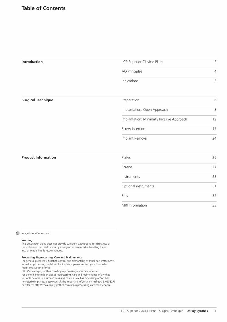
Table of Contents
Introduction
Surgical Technique
Product Information
LCP Superior Clavicle Plate 2
AO Principles 4
Indications 5
Preparation 6
Implantation: Open Approach 8
Implantation: Minimally Invasive Approach 12
Screw Insertion 17
Implant Removal 24
Plates 25
Screws 27
Instruments 28
Optional instruments 31
Sets 32
MRI Information 33
Image intensifier control
WarningThis description alone does not provide sufficient background for direct use ofthe instrument set. Instruction by a surgeon experienced in handling theseinstruments is highly recommended.
Processing, Reprocessing, Care and MaintenanceFor general guidelines, function control and dismantling of multi-part instruments,as well as processing guidelines for implants, please contact your local salesrepresentative or refer to:http://emea.depuysynthes.com/hcp/reprocessing-care-maintenanceFor general information about reprocessing, care and maintenance of Synthesreusable devices, instrument trays and cases, as well as processing of Synthesnon-sterile implants, please consult the Important Information leaflet (SE_023827)or refer to: http://emea.depuysynthes.com/hcp/reprocessing-care-maintenance

LCP Superior Clavicle Plate with lateral extension
LCP Superior Clavicle Plate. Theanatomically precontoured fixationsystem with angular stability for clavicle shaft and lateral clavicle.
Features and Benefits
Lateral holes2.7 mm locking or 2.4 mm cortex screws
Shaft holes 3.5 mm locking or 3.5 mm cortexscrews
Undercuts reduceimpairment of bloodsupply
Recon plate segments allowany necessary plate contouring
Offset screws minimizethe risk of bone splitting
Small diverging screws in lateralend ensure good screw purchaseand increased pull out strength
2 DePuy Synthes LCP Superior Clavicle Plate Surgical Technique
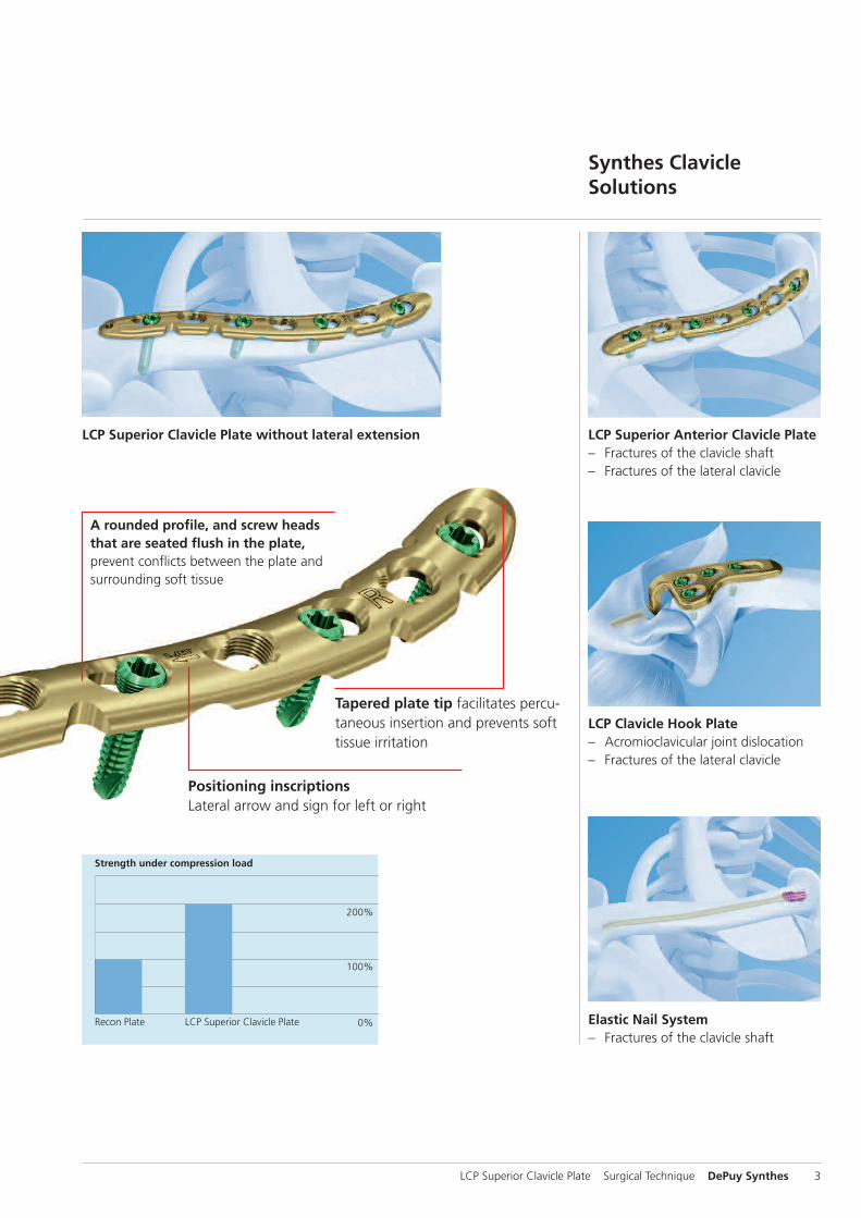
0%
100%
200%
LCP Superior Clavicle Plate Surgical Technique DePuy Synthes 3
LCP Superior Clavicle PlateRecon Plate
Strength under compression load
LCP Superior Clavicle Plate without lateral extension LCP Superior Anterior Clavicle Plate– Fractures of the clavicle shaft– Fractures of the lateral clavicle
LCP Clavicle Hook Plate– Acromioclavicular joint dislocation– Fractures of the lateral clavicle
Elastic Nail System– Fractures of the clavicle shaft
Tapered plate tip facilitates percu-taneous insertion and prevents softtissue irritation
Positioning inscriptionsLateral arrow and sign for left or right
Synthes Clavicle Solutions
A rounded profile, and screw headsthat are seated flush in the plate, prevent conflicts between the plate andsurrounding soft tissue

AO Principles
In 1958, the AO formulated four basic principles, which havebecome the guidelines for internal fixation.1, 2 Those principlesas applied to the LCP Superior Clavicle Plate are:
Anatomic reductionPrecontoured plate assists in anatomic reduction.
Stable fixationLocking screws create a fixed-angle construct providing angular stability.
Preservation of blood supplyTapered end for subcutaneous plate insertion preserves tissueviability. A limited-contact plate design reduces plate-to-bonecontact and helps to preserve the periosteal blood supply.
Early, active mobilizationEarly mobilization per standard AO technique creates an environment for bone healing, expediting a return to optimalfunction.
1 Müller ME, Allgöwer M, Schneider R, Willenegger H (1995) Manual of InternalFixation. 3rd, expanded and completely revised ed. 1991. Berlin, Heidelberg,New York: Springer
2 Rüedi TP, Buckley RE, Moran CG (2007) AO Principles of Fracture Management.2nd expanded ed. 2002. Stuttgart, New York: Thieme
4 DePuy Synthes LCP Superior Clavicle Plate Surgical Technique

Indications
– Fractures of the clavicle shaft– Fractures of the lateral clavicle– Malunions of the clavicle– Non-unions of the clavicle
LCP Superior Clavicle Plate Surgical Technique DePuy Synthes 5

034.
000.
675
AA
30
1004
04
© 0
7/20
10 S
ynth
es, I
nc.
or
its
affi
liate
s A
ll ri
gh
ts r
eser
ved
Sy
nth
es is
tra
dem
ark
of
Syn
thes
, In
c. o
r it
s af
filia
tes
0 10 20 30 40 50 60 70 80 90 100 mm
1.10 Magnification
For use only with the Original AO System ofInstruments and Implants
LCP Superior Clavicle Plate 3.5, Left
Titanium Stainless Steel Shaft holes Length (mm)04.112.081 02.112.081 6 9404.112.083 02.112.083 7 11004.112.085 02.112.085 8 123
Titanium Stainless Steel Shaft holes Length (mm)04.112.007 02.112.007 3 6904.112.011 02.112.011 4 8104.112.013 02.112.013 5 9404.112.091 02.112.091 6 11004.112.093 02.112.093 7 12404.112.095 02.112.095 8 136
Medial LateralMedial Lateral
without lateral extension with lateral extension
Ö034.000.675öAA]ä
123 mm
110 mm
94 mm
69 mm
81 mm
94 mm
110 mm
124 mm
136 mm
8 holes
7 holes
6 holes
5 holes
4 holes
3 holes
034.
000.
675
AA
30
1004
04
© 0
7 /2
010
Syn
thes
, In
c. o
r it
s af
filia
tes
All
rig
hts
res
erve
d
Syn
thes
is t
rad
emar
k o
f Sy
nth
es, I
nc.
or
its
affi
liate
s
0 10 20 30 40 50 60 70 80 90 100 mm
1.10 Magnification
For use only with the Original AO System ofInstruments and Implants
LCP Superior Clavicle Plate 3.5, Right
Titanium Stainless Steel Shaft holes Length (mm)04.112.080 02.112.080 6 9404.112.082 02.112.082 7 11004.112.084 02.112.084 8 123
Titanium Stainless Steel Shaft holes Length (mm)04.112.006 02.112.006 3 6904.112.010 02.112.010 4 8104.112.012 02.112.012 5 9404.112.090 02.112.090 6 11004.112.092 02.112.092 7 12404.112.094 02.112.094 8 136
Lateral Medial Lateral Medial
without lateral extensionwith lateral extension
Ö034.000.675öAA]ä
123 mm
110 mm
94 mm
136 mm
124 mm
110 mm
81 mm
69 mm
8 holes
7 holes
6 holes
5 holes
4 holes
3 holes
94 mm
034.
000.
540
© 1
0/20
08 S
ynth
es, I
nc.
or
its
affi
liate
s A
ll ri
gh
ts r
eser
ved
Sy
nth
es is
tra
dem
ark
of
Syn
thes
, In
c. o
r it
s af
filia
tes
0 10 20 30 40 50 60 70 80 90 100mm
1.10 Magnification
For use only with the Original AO System ofInstruments and Implants
LCP Superior Anterior Clavicle Plate, Left
Titanium Stainless Steel Shaft holes Length (mm)04.112.007 02.112.007 3 6904.112.011 02.112.011 4 8104.112.013 02.112.013 5 9404.112.009 02.112.009 6 10804.112.019 02.112.019 7 12304.112.021 02.112.021 8 135
04.112.027 02.112.027 6 9404.112.029 02.112.029 7 11004.112.031 02.112.031 8 120
120 mm
110 mm
94 mm
69 mm
81 mm
94 mm
108 mm
123 mm
135 mm
Medial Lateral Medial Lateral
without lateral extensionwith lateral extension
8 holes
7 holes
6 holes
5 holes
4 holes
3 holes
Preparation
1Preoperative planning
Complete the preoperative radiographic assessment andprepare the preoperative plan. Use the x-ray templates forLCP Superior Clavicle Plate (Art. No. 034.001.675 for rightand left clavicles) to determine the length of the plate andthe position of the screws.
6 DePuy Synthes LCP Superior Clavicle Plate Surgical Technique

2Position and prepare patient
Position the patient in a supine position on a radiolucentoperating table. Provide enough room to swing the image intensifier 45° in both directions to view the clavicle in two planes intra-operatively.
Notes – Longer tubes for anesthesia may be required.– Prepare the associated arm so that it can be intra-opera-
tively mobilized. The mobilization of the arm can be usedas reduction aid.
LCP Superior Clavicle Plate Surgical Technique DePuy Synthes 7

1Surgical approach (open)
Make a gentle curvilinear incision parallel to the skin clea-vage lines.
Subcutaneous dissection permits identification of the supra-clavicular sensory nerve branches. The major fibers ofthese nerves should be identified and protected with smallvessel loops throughout the surgery.
Carefully divide the platysma to expose the clavicle perios-teum at the deltotrapezial fascia. Minimally dissect the periosteum to expose the fracture.
Precaution: Bone fragments must not be detached from theperiosteum in order to enable proper bone healing. It is criti-cal not to strip any comminuted fragments.
Implantation: Open Approach
8 DePuy Synthes LCP Superior Clavicle Plate Surgical Technique

2Fracture reduction and temporary fixation
Normal length, axis angulation and rotation should be restored.
After exposing the fracture, the two main fragments are dis-tracted and the length of the clavicle is restored. If the boneends are angled or oblique, reduce with a pointed or serratedreduction forceps.
Any large comminuted fragments should also be reducedand held temporarily with small pointed bone clamps or Kirschner wires. Assess and plan for any temporary fixationso as to not interfere with the placement of the definitive fixation implants.
Kirschner wires can be placed through the distal end of theplate to assist with temporary maintenance of the reductionand for plate placement.
Additional options for maintaining the reduction include independent lag screws and lag screws inserted through the plate.
Precaution: Bone fragments must not be detached from the periosteum in order to enable proper bone healing. It is critical not to strip any comminuted fragments.
Option: The LCP Superior Clavicle Plate can be used for bio-logical, bridging osteosynthesis. Only the main fragments arereduced and the actual fracture zone is not engaged withany screw.
LCP Superior Clavicle Plate Surgical Technique DePuy Synthes 9

3Determine plate length and adapt plate
Optional instruments
329.291 Bending Pliers for Clavicular Plates, length 227 mm
329.040/ Bending Iron for Plates 2.4 to 3.5,329.050 length 145 mm
329.300 Bending Press, length 400 mm
Select a plate length appropriate for the fracture.
Due to varying patient anatomy, plate bending may be ne-cessary. Using the bending irons, bending pliers and/or theplate press, contour the plate as needed. For an optimum fit,the plate can be bent at each notch in the plane of the shaft.
To bend the plate, insert it into the jaws of the bending pliersfor clavicle plates at the appropriate notch.
To adjust the S-curve, place the plate between the two notches in the front of the jaws of the bending pliers.
Implantation: Open Approach
10 DePuy Synthes LCP Superior Clavicle Plate Surgical Technique

4Position plate and attach temporarily
Position the plate on the reduced bone, and attach it tem-porarily with a 3.5 mm cortex screw or plate holding forceps.
After plate insertion, check alignment on the bone using animage intensifier.
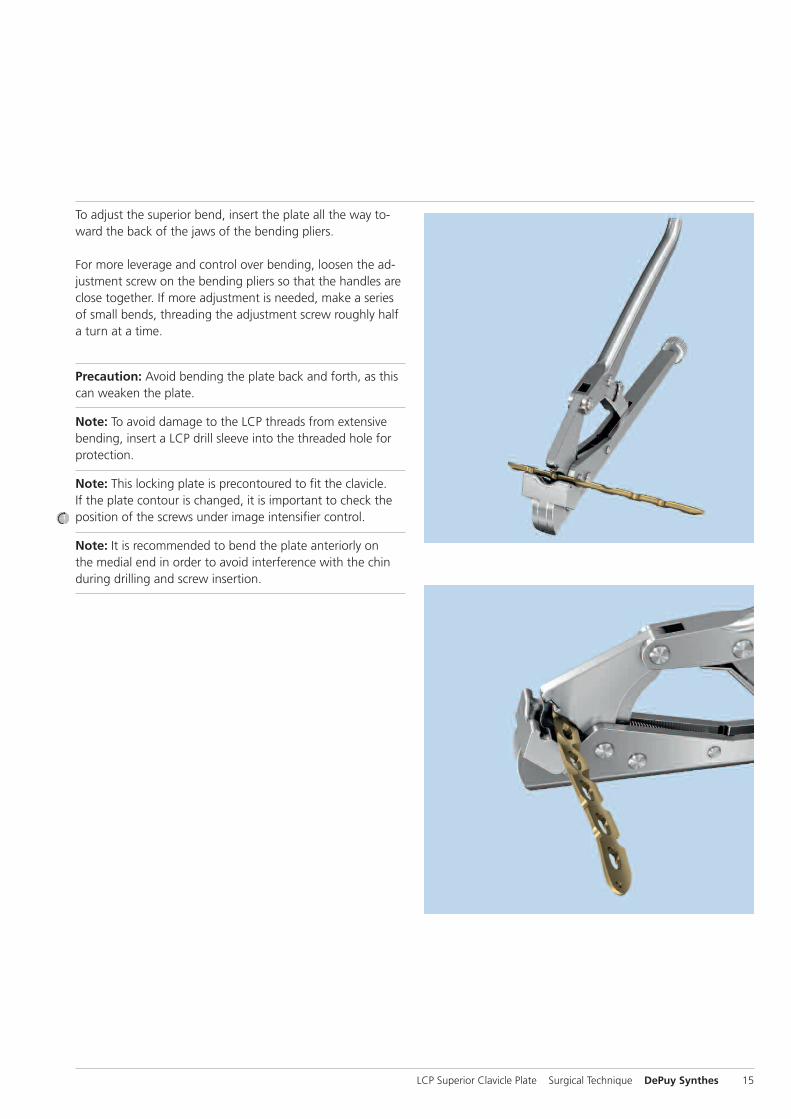
To adjust the superior bend, insert the plate all the way to-ward the back of the jaws of the bending pliers.
For more leverage and control over bending, loosen the ad-justment screw on the bending pliers so that the handles areclose together. If more adjustment is needed, make a seriesof small bends, threading the adjustment screw roughly halfa turn at a time.
Precaution: Avoid bending the plate back and forth, as thiscan weaken the plate.
Note: To avoid damage to the LCP threads from extensivebending, insert a LCP drill sleeve into the threaded hole forprotection.
Note: This locking plate is precontoured to fit the clavicle. If the plate contour is changed, it is important to check theposition of the screws under image intensifier control.
Note: It is recommended to bend the plate anteriorly on the medial end in order to avoid interference with the chinduring drilling and screw insertion.
LCP Superior Clavicle Plate Surgical Technique DePuy Synthes 11

Implantation: Minimally Invasive Approach
1Surgical approach (minimally invasive)
The operation is performed from medial towards lateral tominimize the risk of harming central vessels.
Make a 2 cm incision over the medial end of the clavicle.
Note: To reduce the chance of post-operative interferencebetween the wound and the plate, use a finger to push theskin cranially over the clavicle and cut the skin on the claviclebone. When removing the finger, the skin will glide back andthe cut will be positioned below the clavicle.
The subcutis is carefully spread and dissected to the cortex ofthe medial clavicle. Ensure that soft tissue is removed fromthe anterior medial and the superior lateral parts of the boneto enable plate placement.
12 DePuy Synthes LCP Superior Clavicle Plate Surgical Technique

2Reduce fracture
Normal length, axis angulation and rotation should be re-stored. In some cases, this can be controlled percutaneouslywith one’s fingers or with pointed forceps.
Otherwise, an additional 3 cm incision across the fractureand along the cleavage lines is done. Reduction is accom-plished through distraction and rotation, if required.
Precaution: Bone fragments must not be detached from theperiosteum in order to enable proper bone healing. It is criti-cal not to strip any comminuted fragments.
Option: The LCP Superior Clavicle Plate can be used for bio-logical, bridging osteosynthesis. Only the main fragments arereduced while the actual fracture zone is not engaged withany screws.
LCP Superior Clavicle Plate Surgical Technique DePuy Synthes 13

Implantation: Minimally Invasive Approach
3Determine plate length and adapt plate
Optional instruments
329.291 Bending Pliers for Clavicular Plates, length 227 mm
329.040/ Bending Iron for Plates 2.4 to 3.5,329.050 length 145 mm
329.300 Bending Press, length 400 mm
Select a plate length appropriate for the fracture. The opti-mal plate length can be determined by x-ray or by placing iton the skin and palpating.
Due to varying patient anatomy, plate bending may be ne-cessary. Using the bending irons, bending pliers and/or theplate press, contour the plate as needed. For an optimum fit,the plate can be bent at each notch in the plane of the shaft.
To bend the plate, insert it into the jaws of the bending pliersfor clavicle plates at the appropriate notch.
To adjust the S-curve, place the plate between the two notches in the front of the jaws of the bending pliers.
14 DePuy Synthes LCP Superior Clavicle Plate Surgical Technique
To adjust the superior bend, insert the plate all the way to-ward the back of the jaws of the bending pliers.
For more leverage and control over bending, loosen the ad-justment screw on the bending pliers so that the handles areclose together. If more adjustment is needed, make a seriesof small bends, threading the adjustment screw roughly halfa turn at a time.
Precaution: Avoid bending the plate back and forth, as thiscan weaken the plate.
Note: To avoid damage to the LCP threads from extensivebending, insert a LCP drill sleeve into the threaded hole forprotection.
Note: This locking plate is precontoured to fit the clavicle. If the plate contour is changed, it is important to check theposition of the screws under image intensifier control.
Note: It is recommended to bend the plate anteriorly on the medial end in order to avoid interference with the chinduring drilling and screw insertion.
LCP Superior Clavicle Plate Surgical Technique DePuy Synthes 15

4Insert and position plate
Instrument
323.027 LCP Drill Sleeve 3.5, for Drill Bits � 2.8 mm
LCP drill sleeves are fixed in the medial part of the plate andused as insertion handles. The plate can be palpated andguided percutaneously from the medial to the lateral frag-ment.
Position the plate on the reduced bone, and pull the bone tothe plate by inserting a 3.5 mm cortex screw in both mainfragments (see chapter “Screw Insertion” section 2a).
After plate insertion, check alignment on the bone using animage intensifier.
Implantation: Minimally Invasive Approach
16 DePuy Synthes LCP Superior Clavicle Plate Surgical Technique
Screw Insertion
Determine the combination of screws to be used for fixation.If a combination of locking and cortex screws will be used,cortex screws should be inserted first to pull the bone to theplate.
Note: If the LCP Superior Clavicle Plate is used for bridgingosteosynthesis, a minimum of two locking screws should beused in both main fragments. The actual fracture zone isgenerally not engaged with any screws.
1Verify screw placement
Since the direction of the locking screws depends on thecontour of the plate, final screw position may be verified under image intensifier control with Kirschner wires beforeinsertion. This becomes especially important when the platehas been manually contoured, applied near a joint, or fornon-standard anatomy.
Optional: Observe the direction of the drill bit while drillingunder image intensifier control.
LCP Superior Clavicle Plate Surgical Technique DePuy Synthes 17

Screw Insertion
2Screw fixation
2aFixation with � 3.5 mm cortex screws
Instruments
310.250 Drill Bit � 2.5 mm, length 110/85 mm, for Quick Coupling
323.360 Universal Drill Guide 3.5
319.010 Depth Gauge for Screws � 2.7 to 4.0 mm, measuring range up to 60 mm
314.030 Screwdriver Shaft, hexagonal, small, � 2.5 mm
311.431 Handle with Quick Coupling
Use the 2.5 mm drill bit with the 3.5 universal drill guide topre-drill the bone through both cortices.
Precaution: Avoid contact with the subclavian artery andbrachial plexus when drilling through the clavicle.
To set screws in a neutral position, press the drill guide downin the non-threaded hole. To obtain compression, place thedrill guide at the end of the non-threaded hole away fromthe fracture, being sure not to apply downward pressure onthe spring loaded tip.
For neutral position For compression
18 DePuy Synthes LCP Superior Clavicle Plate Surgical Technique

Insert the appropriate 3.5 mm cortex screw using the hexagonal screwdriver or the hexagonal screwdriver shaft.
Determine the required length of the cortex screw using thedepth gauge.
LCP Superior Clavicle Plate Surgical Technique DePuy Synthes 19

2bFixation with � 3.5 mm locking screws
Note: If a locking screw will be used as the first screw,be sure that the fracture is reduced and the plate is held securely to the bone. This prevents plate rotation as thescrew is locked to the plate.
Instruments
323.027 LCP Drill Sleeve 3.5, for Drill Bits � 2.8 mm
310.284 LCP Drill Bit � 2.8 mm, length 165 mm
319.010 Depth Gauge for Screws � 2.7 to 4.0 mm, measuring range up to 60 mm
314.030 Screwdriver Shaft, hexagonal, small, � 2.5 mmor314.116 Screwdriver Shaft Stardrive 3.5, T15
511.770/773 Torque Limiter, 1.5 Nm
397.705/ Handle for Torque Limiter/Handle with311.431 Quick Coupling
Insert the drill sleeve into a 3.5 mm locking hole until fullyseated. Drill through both cortices with the drill bit.
Precaution: Avoid contact with the subclavian artery andbrachial plexus when drilling through the clavicle.
Remove the drill guide. Use the depth gauge to determinethe screw length.
Screw Insertion
20 DePuy Synthes LCP Superior Clavicle Plate Surgical Technique

Insert the locking screw with the appropriate screwdrivershaft (hexagonal or Stardrive recess) mounted on the 1.5 Nmtorque limiter. Insert the screw manually or by power untila click is heard. If a power tool is used, reduce speed whentightening the head of the locking screw into the plate.
Repeat the above steps for all required shaft holes.
LCP Superior Clavicle Plate Surgical Technique DePuy Synthes 21

2cFixation with � 2.7 mm locking screws (only in plateswith lateral extension)
Instruments
323.061 LCP Drill Sleeve 2.7 (head LCP 2.4), with Scale up to 60 mm, for Drill Bits � 2.0 mm
323.062 Drill Bit � 2.0 mm, with double marking, length 140/115 mm, 3-flute, for Quick Coupling
313.304 Screwdriver Shaft Stardrive, T8, cylindrical, with groove
511.776 Torque Limiter, 0.8 Nm, with AO/ASIF Quick Coupling
03.110.005 Handle for Torque Limiters 0.4/0.8/1.2 Nm
Optional instruments
03.111.005 Depth Gauge for Screws � 2.0 to 2.7 mm, measuring range up to 40 mm
319.010 Depth Gauge for Screws � 2.7 to 4.0 mm, measuring range up to 60 mm
313.301 Holding Sleeve for LCP Screw Stardrive � 2.4/2.7 mm
313.300 Combined Holding Sleeve for Cortex Screws Stardrive � 2.4/2.7 mm
Insert the drill sleeve into a 2.7 mm locking hole until fullyseated. Use the drill bit to drill to the desired depth.
Precaution: Avoid contact with the subclavian artery andbrachial plexus when drilling through the clavicle.
Determine the required length of the screw by using thescale on the drill guide and the drill sleeve. If a single mark-ing is visible on the drill bit, the scale from 0–30 mm applies;if a double marking is visible, the scale from 30–60 mm applies.
Screw Insertion
22 DePuy Synthes LCP Superior Clavicle Plate Surgical Technique

If the depth gauge 319.010 is used for 2.7 mm screws, sub-tract 4 mm from the indicated length to obtain the correctscrew length.
Note: The above mentioned methods result in screws that end flush with the opposite cortex. Should bicortical screws be required, insert screws that are 1–2 mm longerthan measured. Screws near a joint should be shorter than measured.
The 2.7 mm locking screw can be inserted manually or withpower. For manual insertion, use a handle with quick cou-pling. Use the Stardrive screwdriver shaft holding sleeve ifnecessary.
For powered insertion of the 2.7 mm locking screws, use the screwdriver shaft attached to the 0.8 Nm torque limitingattachment.
Precaution: Always use a TLA when inserting LCP lockingscrews to avoid plate, screw and/or screwdriver damage.
Option: Use 2.4 mm cortex screws.
Repeat the above steps for all lateral holes to be used.
LCP Superior Clavicle Plate Surgical Technique DePuy Synthes 23

Implant Removal
Instruments
314.030 Screwdriver Shaft, hexagonal, small, � 2.5 mm
314.116 Screwdriver Shaft Stardrive 3.5, T15
313.304 Screwdriver Shaft Stardrive, T8, cylindrical, with groove, shaft � 3.5 mm, for AO/ASIF Quick Coupling
309.521 Extraction Screw for Screws, � 3.5 mm
309.510 Extraction Screw, for Screws � 1.5 mm and 2.0 mm
To remove the implants, unlock all LCP locking screws beforeremoving them completely. The plate may otherwise rotatewhile the last screw is being removed, which may damagethe soft tissue.
If the LCP locking screws cannot be removed with the screwdriver (e.g. the recess of the screw is damaged or the lockingscrew is stuck in the plate), use an extraction screw with left-handed thread. Loosen the screw by turning the handlecounter clockwise.
Note: It is very important to have the correct instrumentationavailable to ensure trouble free implant removal. The correctscrewdrivers (hexagonal or Stardrive) and the extraction screws are of special importance.
24 DePuy Synthes LCP Superior Clavicle Plate Surgical Technique

Plates
LCP Superior Clavicle Plate3.5 mm, right
Art. No. Holes Length (mm)
0X.112.080 6 94
0X.112.082 7 110
0X.112.084 8 123
LCP Superior Clavicle Plate3.5 mm, left
Art. No. Holes Length (mm)
0X.112.081 6 94
0X.112.083 7 110
0X.112.085 8 123
X = 2: stainless steelX = 4: titanium
All plates and screws are also available sterile packed. For sterile implants, add suffix “S” to article number.
LCP Superior Clavicle Plate Surgical Technique DePuy Synthes 25

Plates
Note: The LCP Superior Clavicle Plate is available in lengthsof 6 to 8 holes.
LCP Superior Clavicle Plate2.7/3.5 mm with lateral extension, right
Art. No. Holes Length (mm)
0X.112.090 6 110
0X.112.092* 7 124
0X.112.094* 8 136
LCP Superior Clavicle Plate2.7/3.5 mm with lateral extension, left
Art. No. Holes Length (mm)
0X.112.091 6 110
0X.112.093* 7 124
0X.112.095* 8 136
Note: If shorter plates are indicated, order the LCP SuperiorAnterior Clavicle Plate 3 to 5 holes.
LCP Superior Anterior Clavicle Plate 2.7/3.5 mm with lateral extension, right
Art. No. Holes Length (mm)
0X.112.006 3 69
0X.112.010 4 81
0X.112.012 5 94
LCP Superior Anterior Clavicle Plate 2.7/3.5 mm with lateral extension, left
Art. No. Holes Length (mm)
0X.112.007 3 69
0X.112.011 4 81
0X.112.013 5 94
X = 2: stainless steelX = 4: titanium
All plates and screws are also available sterile packed. For sterile implants, add suffix “S” to article number.
*Optionally available
26 DePuy Synthes LCP Superior Clavicle Plate Surgical Technique

Screws
Lateral
X02.214–230 Locking Screw Stardrive � 2.7 mm (head LCP 2.4), self-tapping, length 14–30 mm
X01.764–780 Cortex Screw Stardrive � 2.4 mm, self-tapping, length 14–30 mm
Shaft
X12.102–111 Locking Screw Stardrive � 3.5 mm, self-tapping, length 12–30 mmorX13.012–030 Locking Screw � 3.5 mm, self-tapping, length 12–30 mm
X04.812–830 Cortex Screw � 3.5 mm, self-tapping, length 12–30 mm
LCP Superior Clavicle Plate Surgical Technique DePuy Synthes 27

309.521 Extraction Screw for Screws � 3.5 mm
309.510 Extraction Screw, conical, for Screws � 1.5 and 2.0 mm
Instruments
310.250 Drill Bit � 2.5 mm, length 110/85 mm, 2-flute, for Quick Coupling
311.431 Handle with Quick Coupling
310.284 LCP Drill Bit � 2.8 mm with Stop, length165 mm, 2-flute, for Quick Coupling
313.304 Screwdriver Shaft Stardrive, T8, cylindrical,with Groove, shaft � 3.5 mm, for AO/ASIFQuick Coupling
28 DePuy Synthes LCP Superior Clavicle Plate Surgical Technique

319.010 Depth Gauge for Screws � 2.7 to 4.0 mm, measuring range up to 60 mm
314.030 Screwdriver Shaft, hexagonal, small, � 2.5 mm
323.061 LCP Drill Sleeve 2.7 (head LCP 2.4), withScale up to 60 mm, for Drill Bits � 2.0 mm
323.062 Drill Bit � 2.0 mm, with double marking,length 140/115 mm, 3-flute, for QuickCoupling
314.116 Screwdriver Shaft Stardrive 3.5, T15,self-holding, for AO/ASIF Quick Coupling
323.027 LCP Drill Sleeve 3.5, for Drill Bits � 2.8 mm
LCP Superior Clavicle Plate Surgical Technique DePuy Synthes 29

Instruments
511.776 Torque Limiter, 0.8 Nm, with AO/ASIFQuick Coupling
03.110.005 Handle for Torque Limiters 0.4/0.8/1.2 Nm
03.111.005 Depth Gauge for Screws � 2.4 to 2.7 mm,measuring range up to 40 mm
323.360 Universal Drill Guide 3.5
511.773 Torque Limiter, 1.5 Nm, for AO/ASIF Quick Coupling
329.291 Bending Pliers for Clavicular Plates, length 227 mm
30 DePuy Synthes LCP Superior Clavicle Plate Surgical Technique

LCP Superior Clavicle Plate Surgical Technique DePuy Synthes 31
399.770 Reduction Forceps w/Points, speed lock
399.790 Reduction Forceps, toothed, speed lock
399.970 Reduction Forceps w/Points, ratchet lock, L 130 mm
Optional Instruments
399.071 Reduction Forceps w/Points, soft lock, L 126 mm
399.082 Reduction Forceps, toothed, soft lock, L 146 mm
399.074 Reduction Forceps w/Points, wide, soft lock
399.990 Reduction Forceps, toothed, L 140 mm
398.410 Reduction Forceps w/Points, wide, L 132mm

Sets
01.112.038 Tray for LCP Superior Clavicle Plates (Pure Titanium), with Contents, for Vario Case or 01.112.039 Tray for LCP Superior Clavicle Plates (Stainless Steel), with Contents, for Vario Case
01.122.013 Small Fragment Basic Instruments, in Modular Tray, Vario Case System
01.122.015 Screw Insertion Instruments 3.5/4.0, inModular Tray, Vario Case System
Optional Sets
01.122.019 Small Fragment Bending Instruments, in Modular Tray, Vario Case System
01.122.014 Small Fragment Reduction Instruments, in Modular Tray, Vario Case System
01.104.007 Screw Insertion Instruments 2.7/2.4, inModular Tray, Vario Case System
32 DePuy Synthes LCP Superior Clavicle Plate Surgical Technique

LCP Superior Clavicle Plate Surgical Technique DePuy Synthes 33
MRI Information
Torque, Displacement and Image Artifacts according toASTM F2213-06, ASTM F2052-06e1 and ASTM F2119-07Non-clinical testing of a worst case scenario in a 3 T MRI system did not reveal any relevant torque or displacement ofthe construct for an experimentally measured local spatialgradient of the magnetic field of 3.69 T/m. The largest image artifact extended approximately 169 mm from theconstruct when scanned using the Gradient Echo (GE). Testing was conducted on a 3 T MRI system.
Radio Frequency (RF) – induced heating according toASTM F2182-11aNon-clinical electromagnetic and thermal simulations of aworst case scenario lead to temperature rises of 12.2 °C (1.5 T) and 5.8 °C (3 T) under MRI Conditions using RF Coils(whole body averaged specific absorption rate [SAR] of 2 W/kg for 15 minutes).
Precautions: The above mentioned test relies on non-clinicaltesting. The actual temperature rise in the patient will depend on a variety of factors beyond the SAR and time of RF application. Thus, it is recommended to pay particular attention to the following points: – It is recommended to thoroughly monitor patients
undergoing MR scanning for perceived temperatureand/or pain sensations.
– Patients with impaired thermo regulation or temperaturesensation should be excluded from MR scanning procedures.
– Generally it is recommended to use an MRI system withlow field strength in the presence of conductive implants.The employed specific absorption rate (SAR) should be reduced as far as possible.
– Using the ventilation system may further contribute to reduce temperature increase in the body.

0123
Synthes GmbHEimattstrasse 34436 OberdorfSwitzerlandTel: +41 61 965 61 11Fax: +41 61 965 66 00www.depuysynthes.com
This publication is not intended for distribution in the USA.
All surgical techniques are available as PDF files at www.synthes.com/lit ©
DeP
uy S
ynth
es T
raum
a, a
div
isio
n of
Syn
thes
Gm
bH. 2
015.
A
ll rig
hts
rese
rved
. 03
6.00
1.21
6 D
SEM
/TR
M/0
315/
0335
(1)
06/1
5


![CASE REPORT Open Access LCP external fixation ......on LCP external fixation Infection (%) Nonunion (%) Kloen [4] 2009 4 Infected nonunion 1 clavicle, 3 tibia 3.5 or 4.5 mm LCP 3 temporary,](https://static.fdocuments.in/doc/165x107/5f721fabc5180773994e074d/case-report-open-access-lcp-external-fixation-on-lcp-external-fixation-infection.jpg)