LCLS Status and Micro-Bunching Workshop at LBNL Torsten Limberg.
54
LCLS Status and Micro-Bunching Workshop at LBNL Torsten Limberg
-
Upload
alice-small -
Category
Documents
-
view
221 -
download
2
Transcript of LCLS Status and Micro-Bunching Workshop at LBNL Torsten Limberg.

LCLS Status and Micro-Bunching Workshop at LBNL
Torsten Limberg

Workshop Home Page

Workshop 0: ‘S2E & Instabilities’ in Zeuthen 2003

Zeuthen 2003

Laser ‘Heater’

Gain Calculations Zeuthen 2003
More Gain Calculations Zeuthen 2003

Back to LBNL Workshop: ‘Presentations’ Page
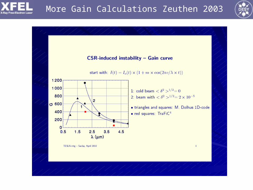
Talk Layout
• Tour Through the Workshop Program
• The LCLS COTR Problems and its Laser Heater
• LCLS Status
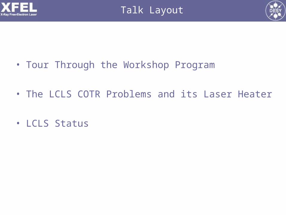
Program…
Microbunching Workshop II – LBNL, 6-8 October, 2008
Semi-Final Program Schedule [last updated 2 October 2008]
Monday, 6 October
Introduction 9:00 – 9:20
• 9:00-9:05 Welcome, S. Gourlay, LBNL AFRD Head
• 9:05–9:20 Workshop Goals + Facilty Info. “Nuts & Bolts”, W. Fawley, LBNL
• Session I - Observations of Microbunching 9:20-12:30 Chairman: M. Cornacchia
• 9:20-9:50 Microbunching Observations at LCLS -- Z. Huang, SLAC
• 9:50-10:20 Microbunching Observations at FLASH -- B. Schmidt, DESY
• 10:20-10:50 Investigation of Microbunching Instability at the SCSS test accelerator -- K. Togawa,
SPRING-8
• 10:50-11:40 Discussion & Coffee Service
• 11:40-12:10 Studies of fragmentation in electron beam energy spectra at SDL –- T. Shaftan, BNL
• Laser pulse shaping and beam structures at SDL -- S. Seletskiy, BNL
• 12:10-12:40 COTR and SASE from Compressed Beams -- A. Lumpkin, FNAL
Program…
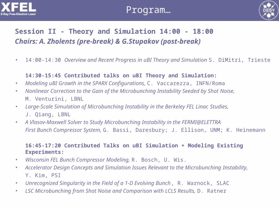
Session II - Theory and Simulation 14:00 - 18:00
Chairs: A. Zholents (pre-break) & G.Stupakov (post-break)
• 14:00-14:30 Overview and Recent Progress in uBI Theory and Simulation S. DiMitri, Trieste
14:30-15:45 Contributed talks on uBI Theory and Simulation:
• Modeling uBI Growth in the SPARX Configurations, C. Vaccarezza, INFN/Roma
• Nonlinear Correction to the Gain of the Microbunching Instability Seeded by Shot Noise,
M. Venturini, LBNL
• Large-Scale Simulation of Microbunching Instability in the Berkeley FEL Linac Studies,
J. Qiang, LBNL
• A Vlasov-Maxwell Solver to Study Microbunching Instability in the FERMI@ELETTRA
First Bunch Compressor System, G. Bassi, Daresbury; J. Ellison, UNM; K. Heinemann
16:45-17:20 Contributed Talks on uBI Simulation + Modeling Existing Experiments:
• Wisconsin FEL Bunch Compressor Modeling, R. Bosch, U. Wis.
• Accelerator Design Concepts and Simulation Issues Relevant to the Microbunching Instability,
Y. Kim, PSI
• Unrecognized Singularity in the Field of a 1-D Evolving Bunch, R. Warnock, SLAC
• LSC Microbunching from Shot Noise and Comparison with LCLS Results, D. Ratner
Program…
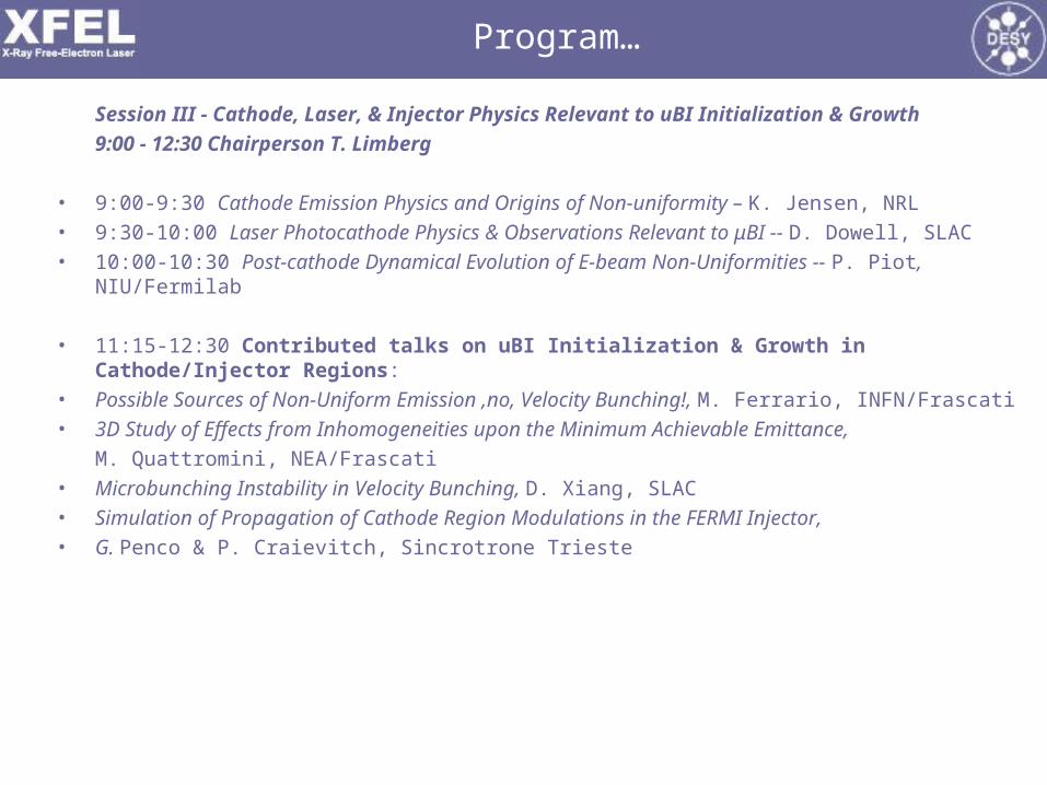
Session III - Cathode, Laser, & Injector Physics Relevant to uBI Initialization & Growth
9:00 - 12:30 Chairperson T. Limberg
• 9:00-9:30 Cathode Emission Physics and Origins of Non-uniformity – K. Jensen, NRL
• 9:30-10:00 Laser Photocathode Physics & Observations Relevant to μBI -- D. Dowell, SLAC
• 10:00-10:30 Post-cathode Dynamical Evolution of E-beam Non-Uniformities -- P. Piot, NIU/Fermilab
• 11:15-12:30 Contributed talks on uBI Initialization & Growth in Cathode/Injector Regions:
• Possible Sources of Non-Uniform Emission ,no, Velocity Bunching!, M. Ferrario, INFN/Frascati
• 3D Study of Effects from Inhomogeneities upon the Minimum Achievable Emittance,
M. Quattromini, NEA/Frascati
• Microbunching Instability in Velocity Bunching, D. Xiang, SLAC
• Simulation of Propagation of Cathode Region Modulations in the FERMI Injector,
• G. Penco & P. Craievitch, Sincrotrone Trieste

Program…
Session IV - Diagnostics & Control 13:30-17:45 Chairpersons,
D. Dowell (pre-break) & M. Ferrario (post-break)• 13:30-14:15 Current state-of-art in OTR physics & diag. setup –
R. Fiorito, U Md., & A. Lumpkin, FNAL
• 14:15-14:40 LCLS OTR setup and COTR studies –
H. Loos, SLAC
• 14:40-15:05 COTR observations at FLASH –
B. Beutner, PSI
• LCLS Laser Heater plans –
P. Emma, SLAC
• FERMI Laser Heater plans –
S. Spampinati, Sincrotrone Trieste
• 16:00-17:15 Contributed talks on Diagnostics and Control:
• E-beam High-Frequency Content on the Bunch Length Measurement and
• Longitudinal Feedback, J. Wu, SLAC
• Two Stage, Single Shot IR CTR Spectrometer, S. Wesch, DESY
• Compressing Electron Bunches with Solenoids, A. Zholents, LBNL
• COTR Mitigation with a Tilted OTR Foil, G. Stupakov, SLAC
• 17:15-17:45 Discussion

Program…
• Near-Term Future Plans at Different Labs
• 9:00-10:20 Plans @ different labs including expt. verification/benchmarking of uBI theory &
• simulation, followed by open general discussion
• DESY FLASH & XFEL plans – T. Limberg
• FERMI Plans -- Injector microbunching characterization using a low energy deflecting cavity
• BNL plans – S. Seletskiy
• Frascati Plans - M. Ferrario
• ANL/FNAL Plans, A. Lumpkin
• Shanghai plans for uBI expt. studies– Z. Huang, SLAC, speaking for D. Wong, Shanghai
• Microbunching Experimental Plans at the Upcoming PSI 250 MeV injector –
Y. Kim, PSI
• Daresbury Plans --- P. Williams
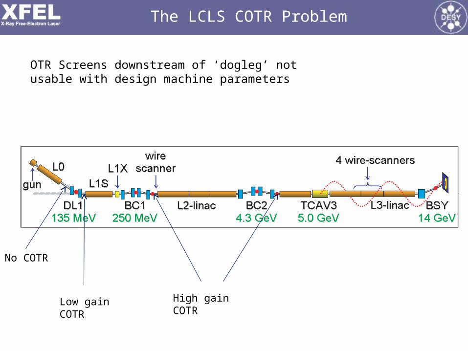
The LCLS COTR Problem
No COTR
Low gain COTR High gain COTR
OTR Screens downstream of ‘dogleg’ not usable with design machine parameters

Scanning the Dogleg Quad

The LCLSThe LCLS Laser-Heater Laser-HeaterP. Emma, P. Emma, forfor The The LCLSLCLS Commissioning Team Commissioning Team
LBNL LBNL µµ-BI Meeting-BI Meeting
Oct. 7, 2008Oct. 7, 2008
LCLSLCLS
Layout and DesignLayout and DesignStatus of InstallationStatus of InstallationCommissioning IssuesCommissioning IssuesExperiments?Experiments?

OTR screens (7)OTR screens (7)YAG screens (7)YAG screens (7)Wire scanners (7)Wire scanners (7)Dipole magnets (8)Dipole magnets (8)Beam stoppers (2)Beam stoppers (2)S-band RF acc. sections (5)S-band RF acc. sections (5)
RF GunRF Gun
SolenoidSolenoid
GunGunSpectrometerSpectrometer
RFRFDeflectorDeflector
X-band RFX-band RFacc. sectionacc. section
BC1BC1L1SL1S
L0aL0a
L0bL0b
2-km point in 3-km SLAC linac2-km point in 3-km SLAC linac
LCLSLCLS Injector Layout Injector Layout
135-MeV135-MeVSpectrometerSpectrometer
EmittanceEmittanceScreens/WiresScreens/Wires
EmittanceEmittanceScreen/WiresScreen/Wires
135 MeV135 MeV
6 MeV6 MeV
250 MeV250 MeV
TD11TD11stopperstopper
Comm
ission
ed in
‘07
Comm
ission
ed in
‘07
Laser-HeaterLaser-Heater

FEL limitFEL limit
LCLS Slice Energy Spread Tolerance
Z. Huang et al., http://prst-ab.aps.org/abstract/PRSTAB/v7/i7/e074401Z. Huang et al., http://prst-ab.aps.org/abstract/PRSTAB/v7/i7/e074401
~40 keV at 1 nC operating point~40 keV at 1 nC operating point

The LCLS Laser Heater (135 MeV)
suggested by Saldin suggested by Saldin et al.et al.


Laser Heater Simulations Z. Huang et al., FEL’04
Example of longitudinal phase space at 14 GeV with 8% initial Example of longitudinal phase space at 14 GeV with 8% initial modulation at 150-modulation at 150-µµm modulationm modulation

Layout of the Laser Heater Optical System in the Laser Lab
IR IR Laser Laser
SystemSystem
UV UV Conversion Conversion
UnitUnit
Path Length Path Length AdjusterAdjuster
PH1PH1
UV beamUV beam
PC & PC & polarizerpolarizer
Energy controlEnergy control
Waveplate Waveplate & polarizer& polarizer
PH2PH2
Pulse Pulse StretcherStretcher S
hu
tte
rS
hu
tte
r
3 lens 3 lens TelescopeTelescope
To streak To streak cameracamera
to vertical to vertical transport tubetransport tube
Adjustment of the telescope Adjustment of the telescope changes the beam size in changes the beam size in
the heater-undulatorthe heater-undulator
Sasha GilevichSasha Gilevich
photophotodiodediode
MH2MH2
MH3MH3
wave wave plateplate
shuttershutter
OTROTRscreensscreens
powerpowermetermeter
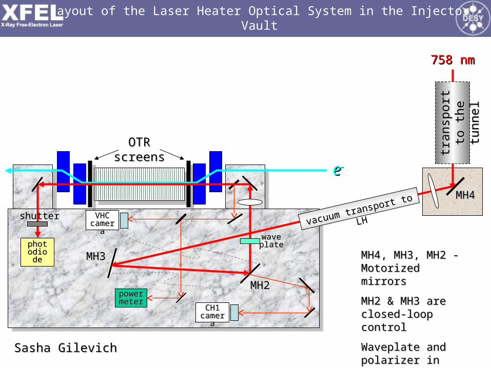
Layout of the Laser Heater Optical System in the Injector Vault
Sasha GilevichSasha Gilevich
MH4, MH3, MH2 - MH4, MH3, MH2 - Motorized mirrorsMotorized mirrors
MH2 & MH3 are MH2 & MH3 are closed-loop controlclosed-loop control
Waveplate and Waveplate and polarizer in front of polarizer in front of both cameras both cameras
vacuum transport to LH
vacuum transport to LH
tran
spor
t to
tr
ansp
ort
to
the
tunn
elth
e tu
nnel
MH4MH4
758 nm758 nm
VHCVHCcameracamera
CH1 CH1 cameracamera
ee
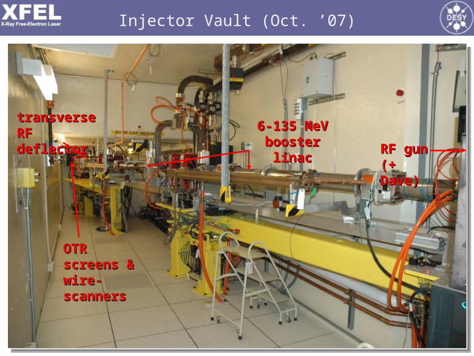
Injector Vault (Oct. ’07)
transverse transverse RF deflectorRF deflector
RF gunRF gun(+ Dave)(+ Dave)
6-135 MeV 6-135 MeV booster linacbooster linac
OTR screens OTR screens & wire-& wire-scannersscanners
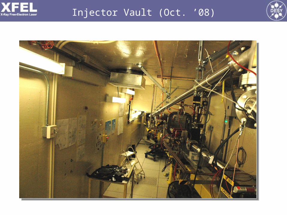
Injector Vault (Oct. ’08)

IR & UV Laser Vertical Transport in Vault
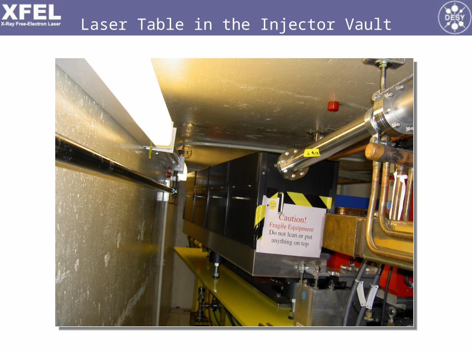
Laser Table in the Injector Vault
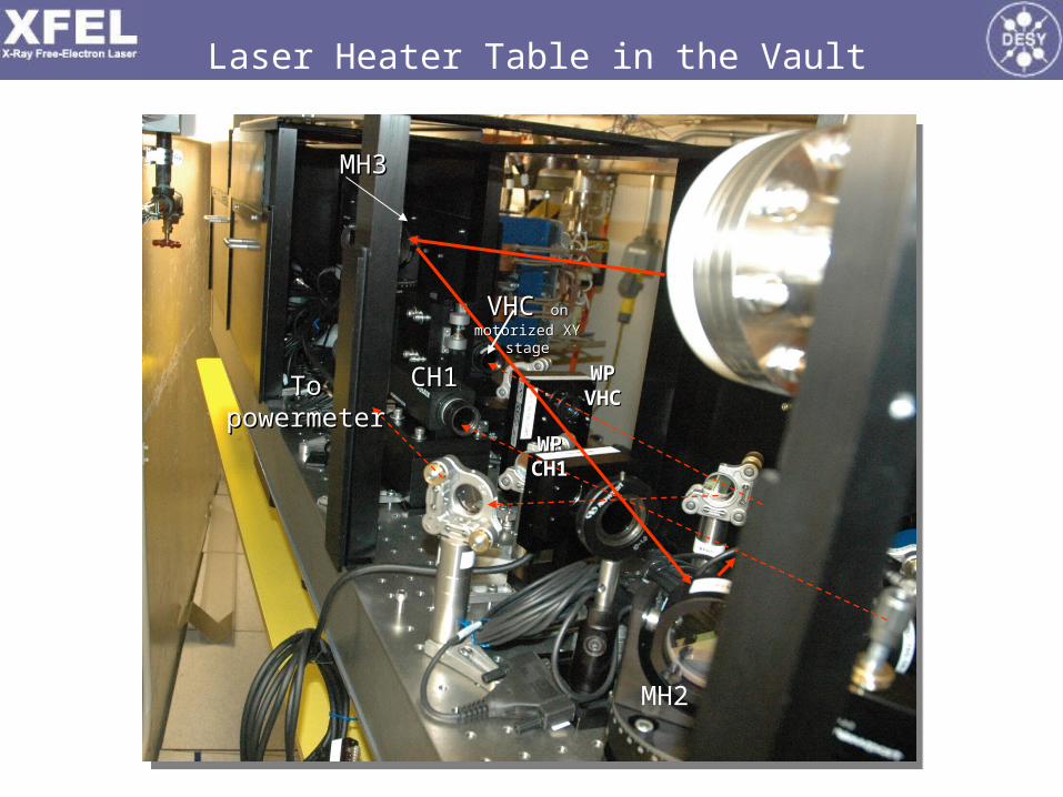
Laser Heater Table in the Vault
MH3MH3
MH2
CH1CH1
VHC VHC on on
motorized XY stagemotorized XY stage
To To powermeterpowermeter
WP WP CH1CH1
WP WP VHCVHC

Laser Heater Table in the Vault
WaveplateWaveplate
From From MH2MH2
50% 50% beamsplitterbeamsplitter
To VHCTo VHC
MH1MH1
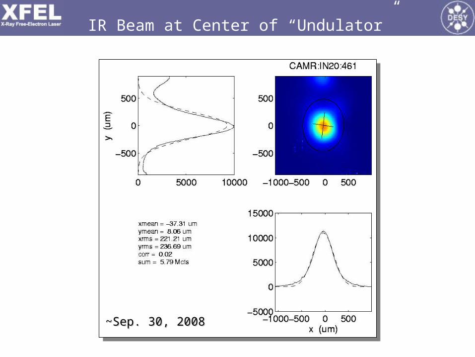
IR Beam at Center of “Undulator”
~Sep. 30, 2008~Sep. 30, 2008

Laser Heater Controls Panel
Matt BoyesMatt Boyes

Damping of COTR? (1 nC, 40 keV rms heating)
BC1BC1::
COTR suppression for: 2COTR suppression for: 2EE//EE00RR5656 >> >>
(40 keV)/(250 MeV)(40 keV)/(250 MeV)(39 mm) = 39 (39 mm) = 39 µµm >> 1 m >> 1 µµmm
BC2BC2::
COTR suppression for: 2COTR suppression for: 2EE//EE00CC11RR5656 >> >>
(40 keV)/(4.3 GeV)(40 keV)/(4.3 GeV)4.5(25 mm) = 7 4.5(25 mm) = 7 µµm >> 1 m >> 1 µµmm
similar numbers at 250 pC with similar numbers at 250 pC with EE = 20 keV = 20 keV

RF Deflector (LOLA) + RF Deflector (LOLA) + special lattice configuration special lattice configuration in spectrometer allows fine in spectrometer allows fine measurement of time-sliced measurement of time-sliced energy spread (to <6 keV)energy spread (to <6 keV)
EE 6 keV rms 6 keV rms (40 (40 m)m)
OTR screens (7)OTR screens (7)YAG screens (7)YAG screens (7)Wire scanners (7)Wire scanners (7)Dipole magnets (8)Dipole magnets (8)Beam stoppers (2)Beam stoppers (2)S-band RF acc. sections (5)S-band RF acc. sections (5)
RF GunRF Gun
SolenoidSolenoid
GunGunSpectrometerSpectrometer
RFRFDeflectorDeflector
X-band RFX-band RFacc. sectionacc. section
BC1BC1L1SL1S
L0aL0a
L0bL0b
2-km point in 3-km SLAC linac2-km point in 3-km SLAC linac
135-MeV135-MeVSpectrometerSpectrometer
EmittanceEmittanceScreens/WiresScreens/Wires EmittanceEmittance
Screen/WiresScreen/Wires
135 MeV135 MeV 250 MeV250 MeV
TD11TD11stopperstopper
Laser-HeaterLaser-Heater
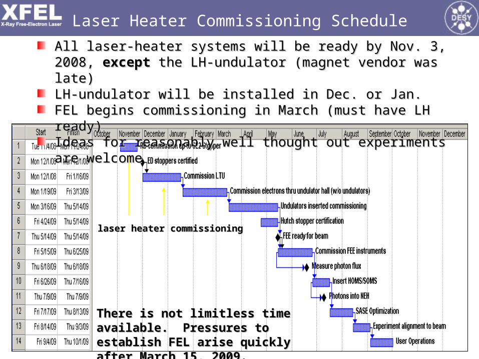
Laser Heater Commissioning Schedule
laser heater commissioninglaser heater commissioning
All laser-heater systems will be ready by Nov. 3, 2008, All laser-heater systems will be ready by Nov. 3, 2008, exceptexcept the the LH-undulator (magnet vendor was late)LH-undulator (magnet vendor was late)LH-undulator will be installed in Dec. or Jan.LH-undulator will be installed in Dec. or Jan.FEL begins commissioning in March (must have LH ready)FEL begins commissioning in March (must have LH ready)Ideas for reasonably well thought out experiments are welcomeIdeas for reasonably well thought out experiments are welcome
There is not limitless time available. There is not limitless time available. Pressures to establish FEL arise Pressures to establish FEL arise quickly after March 15, 2009.quickly after March 15, 2009.

LCLSLCLS Commissioning Status Commissioning StatusP. Emma, forP. Emma, for The The LCLSLCLS Commissioning Team Commissioning Team
LCLS SAC MeetingLCLS SAC Meeting
October 20, 2008October 20, 2008
LCLSLCLS
Machine PerformanceMachine Performance
Estimated FEL PowerEstimated FEL Power
Present StabilityPresent Stability
Ultra-Short Pulse PossibilitiesUltra-Short Pulse Possibilities

Linac Coherent Light Source at Linac Coherent Light Source at SLACSLAC
Injector (35Injector (35ºº))at 2-km pointat 2-km point
Existing 1/3 Linac (1 km)Existing 1/3 Linac (1 km)(with modifications)(with modifications)
Near Experiment HallNear Experiment Hall
Far ExperimentFar ExperimentHallHall
Undulator (130 m)Undulator (130 m)
X-FEL based on last 1-km of existing linacX-FEL based on last 1-km of existing linacX-FEL based on last 1-km of existing linacX-FEL based on last 1-km of existing linac
New New ee Transfer Line (340 m) Transfer Line (340 m)
1.5-15 Å1.5-15 Å1.5-15 Å1.5-15 Å
X-ray X-ray Transport Transport Line (200 m)Line (200 m)
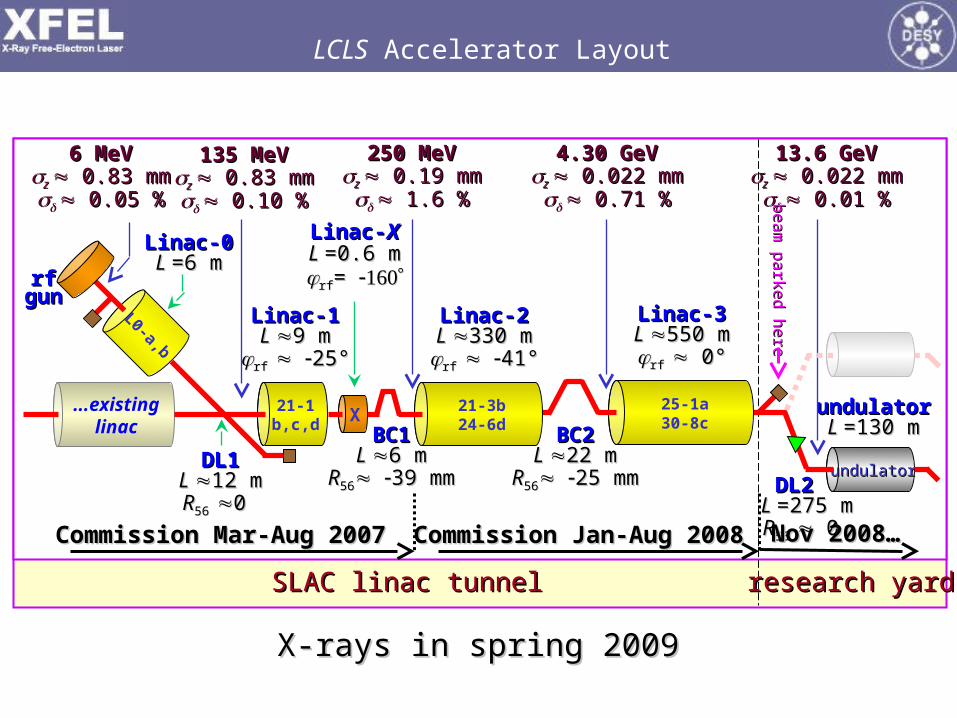
LCLS Accelerator Layout
SLAC linac tunnelSLAC linac tunnel research yardresearch yard
Linac-0Linac-0L L =6 m=6 m
Linac-1Linac-1L L 9 m9 m
rf rf 25°25°
Linac-2Linac-2L L 330 m330 mrf rf 41°41°
Linac-3Linac-3L L 550 m550 mrf rf 0° 0°
BC1BC1L L 6 m6 m
RR5656 39 mm39 mm
BC2BC2L L 22 m22 m
RR5656 25 mm25 mm DL2 DL2 L L =275 m=275 mRR56 56 0 0
DL1DL1L L 12 m12 mRR56 56 0 0
undulatorundulatorL L =130 m=130 m
6 MeV6 MeVz z 0.83 mm 0.83 mm 0.05 %0.05 %
135 MeV135 MeVz z 0.83 mm 0.83 mm 0.10 %0.10 %
250 MeV250 MeVz z 0.19 mm 0.19 mm 1.6 %1.6 %
4.30 GeV4.30 GeVz z 0.022 mm 0.022 mm 0.71 %0.71 %
13.6 GeV13.6 GeVz z 0.022 mm 0.022 mm 0.01 %0.01 %
Linac-Linac-XXL L =0.6 m=0.6 mrfrf= =
21-1b,c,d
...existinglinac
L0-a,b
rfrfgungun
21-3b24-6dX
25-1a30-8c
undulatorundulator
Commission Mar-Aug 2007Commission Mar-Aug 2007 Commission Jan-Aug 2008Commission Jan-Aug 2008 Nov 2008…Nov 2008…
X-rays in spring 2009X-rays in spring 2009
be
am
pa
rked
he
reb
ea
m p
arke
d h
ere

Phase-II Commissioning Highlights (2008)
Injector Commissioning: Apr-Aug, 2007 (DONE)
Phase-II Commissioning: Dec-Aug, 2008 (DONE)
Great drive-laser uptime (99%) and good performance
Projected emittances 0.7-1.6 m at 0.25 nC, 10 GeV
Routine 30-Hz e to 14 GeV (~24/7 with ~90% up-time)
Bunch compression fully demonstrated down to 1-2 µm
Many beam & RF feedback systems running well
Electron bunch appears bright enough to drive 1.5-Å FEL
20-pC bunch with 0.14-µm emittance (& ~10 fs length?)

Laser Spatial and Temporal Shaping in 2008
Temporal shape (6.6 ps FWHM)Temporal shape (6.6 ps FWHM)Spatial shape on cathode using irisSpatial shape on cathode using iris
S. Gilevich, G. Hays, P. Hering, A. Miahnahri, W. White S. Gilevich, G. Hays, P. Hering, A. Miahnahri, W. White
99% Drive Laser up time!99% Drive Laser up time!
22RR = 1.4 mm = 1.4 mm20082008
6.6 ps6.6 ps
20082008
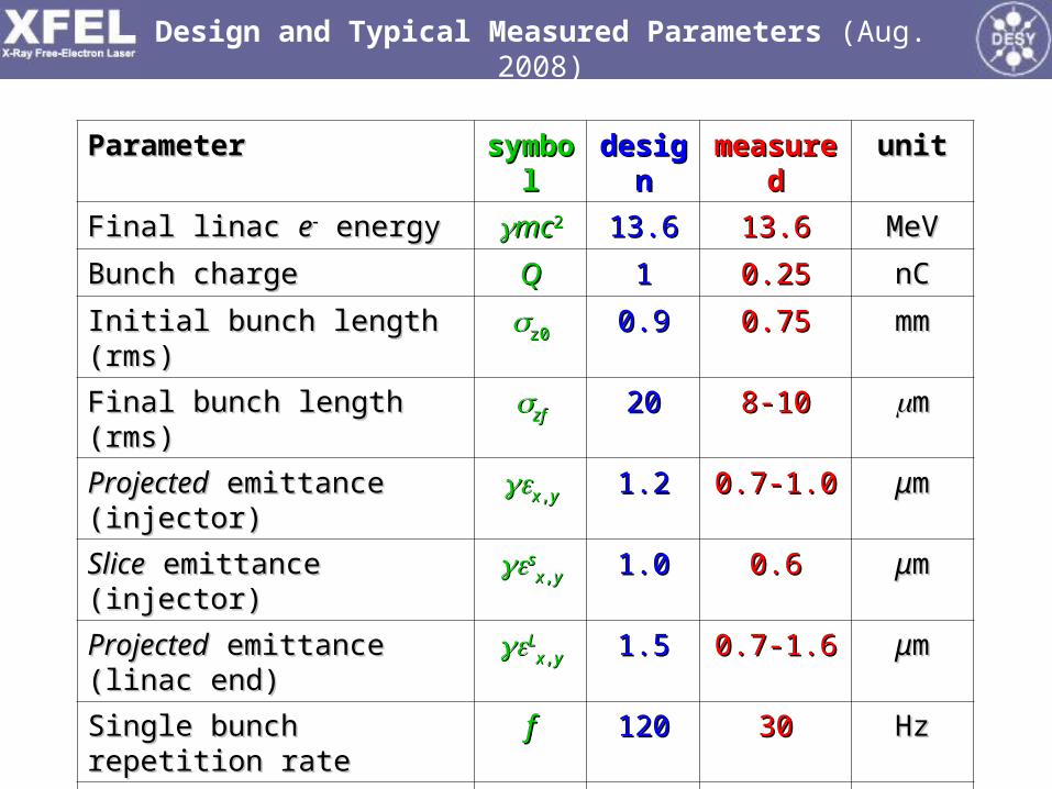
Design and Typical Measured Parameters (Aug. 2008)
ParameterParameter symbolsymbol designdesign measuredmeasured unitunit
Final linac Final linac ee energy energy mcmc22 13.613.6 13.613.6 MeVMeV
Bunch chargeBunch charge QQ 11 0.250.25 nCnC
Initial bunch length (rms)Initial bunch length (rms) z0z0 0.90.9 0.750.75 mmmm
Final bunch length (rms)Final bunch length (rms) zfzf 2020 8-108-10 mm
ProjectedProjected emittance (injector) emittance (injector) xx,,yy 1.21.2 0.7-1.00.7-1.0 μμmm
SliceSlice emittance (injector) emittance (injector) ssxx,,yy 1.01.0 0.60.6 μμmm
ProjectedProjected emittance (linac end) emittance (linac end) LLxx,,yy 1.51.5 0.7-1.60.7-1.6 μμmm
Single bunch repetition rateSingle bunch repetition rate ff 120120 3030 HzHz
RF gun field at cathodeRF gun field at cathode EEgg 120120 115115 MV/mMV/m
Laser energy on cathodeLaser energy on cathode uull 250250 20-15020-150 μμJJ
Laser diameter on cathodeLaser diameter on cathode 22RR 1.51.5 1.21.2 mmmm
Cathode quantum efficiencyCathode quantum efficiency QEQE 66 0.7-70.7-7 101055

OTR screenOTR screen
95%95%area cutarea cut
Gaussian overlay not usedGaussian overlay not used
Projected Emittance <1.2 μm at 1 nC (135 MeV)
xx = 1.07 = 1.07 μμmm
yy = 1.11 = 1.11 μμmm
mee
ts
mee
ts
inje
ctor
inje
ctor
goals
goals
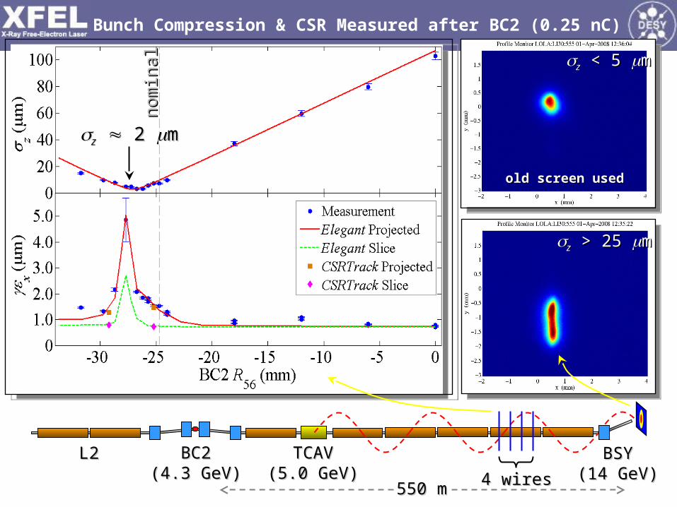
Bunch Compression & CSR Measured after BC2 (0.25 nC)
zz > 25 > 25 mm
BC2BC2(4.3 GeV)(4.3 GeV)
BSYBSY(14 GeV)(14 GeV)
TCAVTCAV(5.0 GeV)(5.0 GeV)
550 m550 m
zz < 5 < 5 mm
old screen usedold screen used
L2L2
4 wires4 wires
zz 2 2 mmno
min
alno
min
al

L0L0
gungun
L3L3L2L2XX
DL1 BC1 DL2
L1L1
zz11
1111 VV11
zz22
2222 VV22
33
VV33
00VV00
Laser & Electron-Based Feedback Systems
D. Fairley, D. Fairley, J. WuJ. Wu
BPMsBPMsCER detectorsCER detectors
Longitudinal Loops Stabilize:Longitudinal Loops Stabilize:DL1 energyDL1 energyBC1 energyBC1 energyBC1 bunch lengthBC1 bunch lengthBC2 energyBC2 energyBC2 bunch lengthBC2 bunch lengthFinal energyFinal energy
BC2
Steering LoopSteering Loop
LaserLaser
Transverse Loops Stabilize:Transverse Loops Stabilize:Laser spot on cathodeLaser spot on cathodeGun launch angleGun launch angleInjector trajectoryInjector trajectoryX-band cavity positionX-band cavity positionLinac trajectory (2)Linac trajectory (2)Undulator traj. (future)Undulator traj. (future)

Bunch Length & Energy Feedback Systems
QQ = 0.25 nC = 0.25 nC
QQ221/21/2//QQ = 1.5% = 1.5%bunchbunchchargecharge
DL1 energyDL1 energy BC1 energyBC1 energy
BC2 energyBC2 energy Final Final ee energy energy
BC2 peak currentBC2 peak currentBC1 peak currentBC1 peak current216 216 ± 12 A± 12 A 2170 2170 ± 217 A± 217 A
0.09% rms0.09% rms 0.03% rms0.03% rms
0.05% rms0.05% rms0.03% rms0.03% rms
Charge feedback:Charge feedback:
Edge Radiation
Beam
Paraboloid
Beam Splitter
Mesh Filter
Pyro Detector
Edge Radiation
Beam
Paraboloid
Beam Splitter
Mesh Filter
Pyro Detector
Edge Radiation
Beam
Paraboloid
Beam Splitter
Mesh Filter
Pyro Detector
Edge Radiation
Beam
Paraboloid
Beam Splitter
Mesh Filter
Pyro Detector
Edge Radiation
Beam
Paraboloid
Beam Splitter
Mesh Filter
Pyro Detector
Edge Radiation
Beam
Paraboloid
Beam Splitter
Mesh Filter
Pyro Detector
Edge Radiation
Beam
Paraboloid
Beam Splitter
Mesh Filter
Pyro Detector
Edge Radiation
Beam
Paraboloid
Beam Splitter
Mesh Filter
Pyro Detector
CSR-based bunch CSR-based bunch length monitorlength monitor

Normalized phase space centroid jitter after BC1 (~4% of rms beam size)
D. RatnerD. Ratner
Stability is Stability is not so far not so far from our from our
goal (~10%)goal (~10%)
… … near near end of linacend of linac (10-15% of rms beam size) (10-15% of rms beam size)
Thanks to Thanks to ControlsControls group for group for new BPM new BPM
electronics!electronics!
RMS RMS AAxNxN = 14% = 14% RMS RMS AAyNyN = 9% = 9%
EE//EE jitter jitter 0.03% 0.03%
QQ//QQ jitter jitter 1.5% 1.5%
RMS RMS AAxNxN = 3.9% = 3.9% RMS RMS AAyNyN = 3.4% = 3.4%
QQ = 0.25 nC = 0.25 nC
1-1- beam beam sizesize
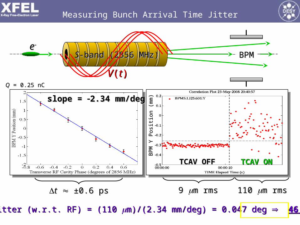
Now measure BPM jitter both Now measure BPM jitter both with transverse RF OFF, and with transverse RF OFF, and then ON (at constant phase)then ON (at constant phase)
tt ±0.6 ps±0.6 ps
slope = slope = 2.34 mm/deg2.34 mm/deg
9 9 m rmsm rms 110 110 m rmsm rms
TCAV ONTCAV ONTCAV OFFTCAV OFF
BPM
Y P
ositi
on (
mm
)B
PM Y
Pos
ition
(m
m)
Measuring Bunch Arrival Time Jitter
ee
VV((tt))
SS-band (2856 MHz)-band (2856 MHz) BPMBPM
Timing Jitter (w.r.t. RF) = (110 Timing Jitter (w.r.t. RF) = (110 m)/(2.34 mm/deg) = 0.047 deg m)/(2.34 mm/deg) = 0.047 deg 46 fsec rms46 fsec rms
QQ = 0.25 nC = 0.25 nC

long long weekend weekend
run at run at 0.25 nC 0.25 nC with no with no tuningtuning
Emittance Near End of Linac Over Long Weekend
(3.3 days) May 24, 2008 00:01 to May 27 09:00(3.3 days) May 24, 2008 00:01 to May 27 09:00
((xxyy))1/21/2 = 1.04 = 1.04 mm

Beam Appears Bright Enough for FEL Saturation at 0.15 nm
Calculation based on measured end-of-linac Calculation based on measured end-of-linac projectedprojected emittance values, emittance values, measured peak current, and design undulator parameters (assuming undulator measured peak current, and design undulator parameters (assuming undulator alignment and alignment and 0.01% rms slice energy spread – not yet measurable) 0.01% rms slice energy spread – not yet measurable)
M. Xie method, with wakesM. Xie method, with wakes
FEL Power3D Gain Length
FEL Power3D Gain Length
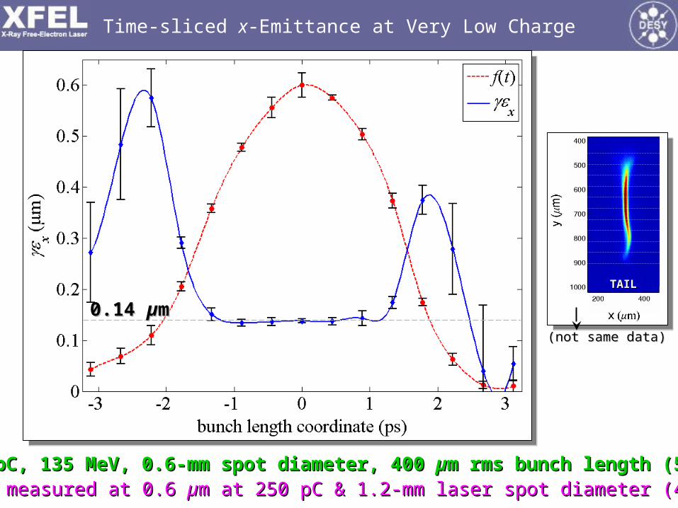
Time-sliced x-Emittance at Very Low Charge
20 pC, 135 MeV, 0.6-mm spot diameter, 400 20 pC, 135 MeV, 0.6-mm spot diameter, 400 µµm rms bunch length (5 A)m rms bunch length (5 A)
TAILTAIL
(not same data)(not same data)
Also measured at 0.6 Also measured at 0.6 µµm at 250 pC & 1.2-mm laser spot diameter (40 A)m at 250 pC & 1.2-mm laser spot diameter (40 A)
0.14 0.14 µµmm

zz 1 1 m ?m ?
8 kA?8 kA?
LiTrackLiTrack(no CSR)(no CSR)
Measurements and Simulations for 20-pC Bunch at 14 GeV
Photo-diode signalPhoto-diode signal on OTR screen after BC2 shows on OTR screen after BC2 shows minimum compression at L2-linac phase of -34.5 deg.minimum compression at L2-linac phase of -34.5 deg.
Horizontal projected emittance Horizontal projected emittance measuredmeasured at 10 GeV, at 10 GeV, after BC2, using 4 wire-scanners.after BC2, using 4 wire-scanners.
Y. DingY. Ding
LCLS FEL LCLS FEL simulationsimulation at 1.5 at 1.5 ÅÅ based on measured based on measured injector beam and injector beam and ElegantElegant tracking, tracking, with CSR, at 20 pC.with CSR, at 20 pC.
1.5 Å1.5 Å,,3.63.610101111 photons photonsIIpkpk = 4.8 kA = 4.8 kA 0.4 µm0.4 µm
SIMULATED FEL PULSESIMULATED FEL PULSE
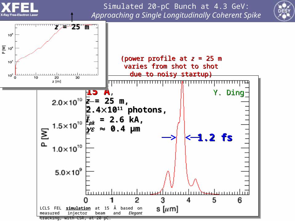
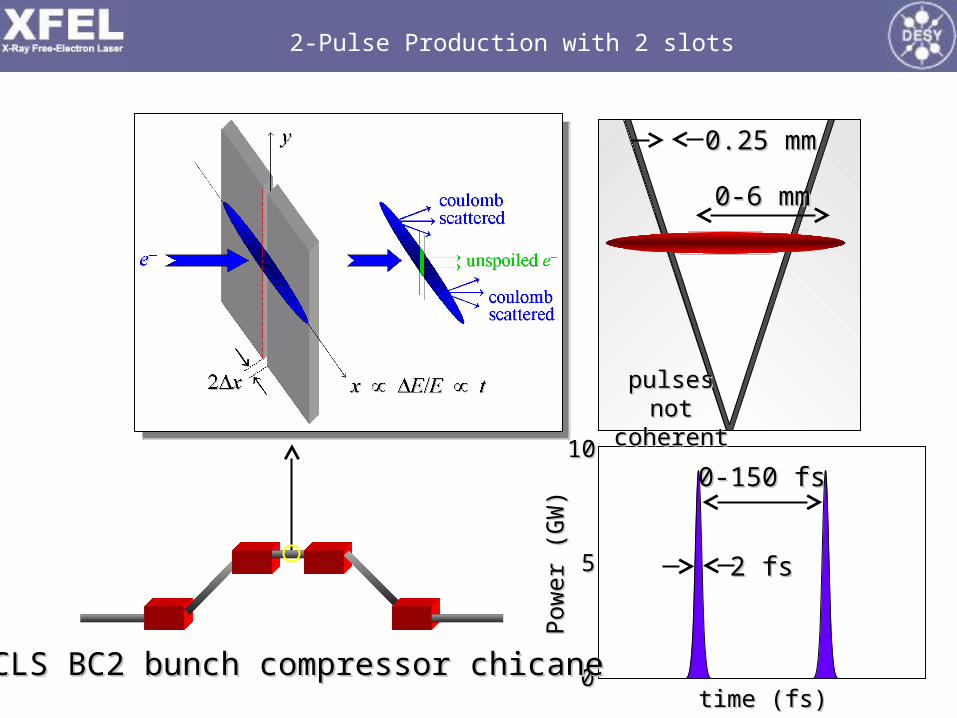
Simulated 20-pC Bunch at 4.3 GeV:Approaching a Single Longitudinally Coherent Spike
Y. DingY. Ding15 Å15 Å,zz = 25 m, = 25 m,2.42.410101111 photons, photons,IIpkpk = 2.6 kA, = 2.6 kA, 0.4 µm0.4 µm
(power profile at (power profile at zz = 25 m varies from = 25 m varies from shot to shot due to noisy startup)shot to shot due to noisy startup)
1.2 fs1.2 fs
zz = 25 m = 25 m
LCLS FEL LCLS FEL simulationsimulation at 15 at 15 ÅÅ based on measured based on measured injector beam and injector beam and ElegantElegant tracking, tracking, with CSR, at 20 pC.with CSR, at 20 pC.
time (fs)time (fs)
Pow
er (
GW
)P
ower
(G
W)
00
1010
55
LCLS BC2 bunch compressor chicaneLCLS BC2 bunch compressor chicane
0-150 fs0-150 fs
2 fs2 fs
2-Pulse Production with 2 slots
0-6 mm0-6 mm
0.25 mm0.25 mm
pulses not pulses not coherentcoherent
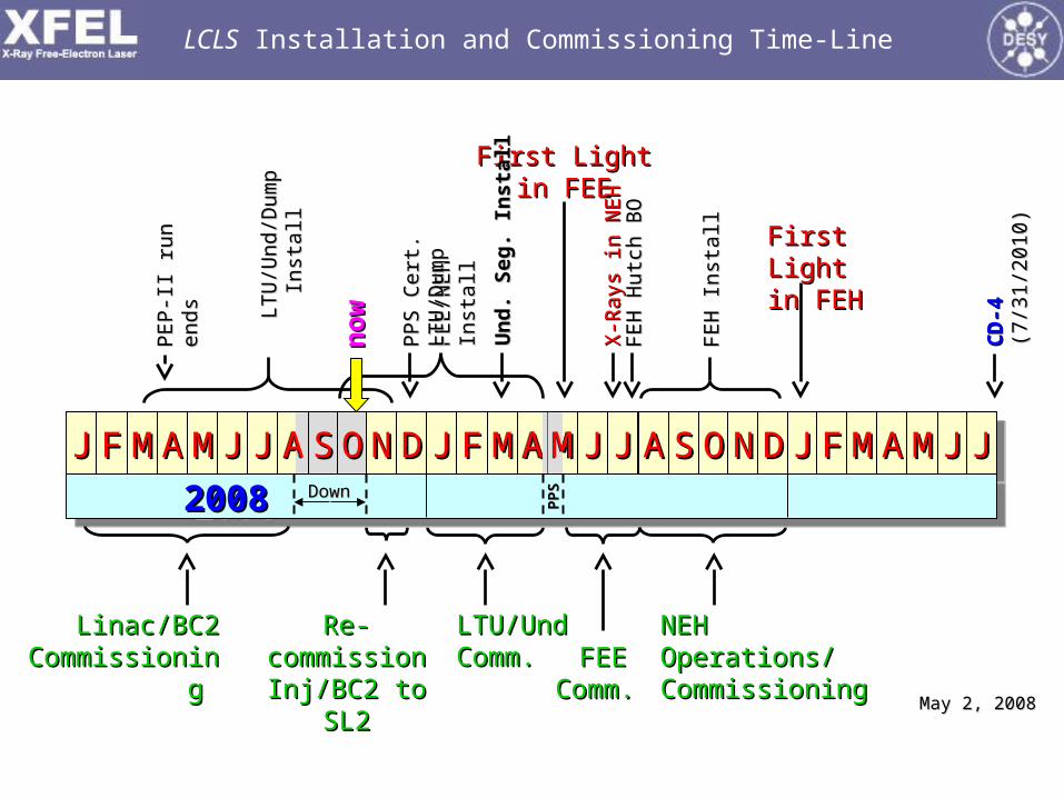
LCLS Installation and Commissioning Time-Line
LTU
/Und
/Dum
p
LTU
/Und
/Dum
p
Inst
all
Inst
all
Re-Re-commission commission
Inj/BC2 to SL2Inj/BC2 to SL2
LTU/LTU/UndUndComm. Comm.
First LightFirst Lightin FEEin FEE
PEP-I
I ru
n
PEP-I
I ru
n
ends
ends
FEE/N
EH
In
stall
FEE/N
EH
In
stall
PPS C
ert
. LT
U/D
um
pPPS C
ert
. LT
U/D
um
p
FEH
In
stall
FEH
In
stall
CD
-4C
D-4
(7
/31
/201
0)
(7/3
1/2
01
0)
X-R
ays
in N
EH
X-R
ays
in N
EH
First LightFirst Lightin FEHin FEH
NEH NEH Operations/ Operations/ CommissioningCommissioning
JJJJ FFFF MMMM AAAA MMMM JJJJ JJJJ AAAA SSSS DDDD JJJJ FFFF MMMM AAAA MMMM JJJJ JJJJ AAAA SSSS OOOO NNNN DDDD JJJJ FFFF MMMM AAAA MMMM JJJJ JJJJOONNAA
2008 2009 20102008 2009 2010 2008 2009 20102008 2009 2010DownDown
PP
SP
PS
AAMM
no
wn
ow
Linac/BC2 Linac/BC2 CommissioninCommissionin
g g FEEFEE
Comm. Comm. May 2, 2008May 2, 2008
FEH
Hutc
h B
OFE
H H
utc
h B
O
Un
d.
Seg
. In
sta
llU
nd
. S
eg
. In
sta
ll


