LCLS-II Cryogenic Facility Compressor Vibration Assessment ...
10
September 2, 2015 LCLSII-TN-15-30 LCLS-II Cryogenic Facility Compressor Vibration Assessment Woodside, California LCLS-II TN-15-30 9/2/2015 Author: WILSON, IHRIG & ASSOCIATES, INC.
Transcript of LCLS-II Cryogenic Facility Compressor Vibration Assessment ...

September 2, 2015 LCLSII-TN-15-30
LCLS-II Cryogenic Facility Compressor Vibration Assessment
Woodside, California
LCLS-II TN-15-30
9/2/2015
Author: WILSON, IHRIG & ASSOCIATES, INC.
L C L S - I I T E C H N I C A L N O T E
September 2, 2015 LCLSII-TN-15-30 2
Summary
Based on information provided by SLAC, motions on the order of a micron or less can
be tolerated by the continuous-wave superconducting linear accelerators. Recent
measurements conducted by SLAC staff at the Jefferson Laboratory (JLAB) in Newport
News, Virginia indicate that vibration caused by the cryogenic helium compressors at the JLAB
facility are well below one micron, and thus they do not pose a problem. Extrapolation of
those results to the current Project configuration indicates that the vibration in the SLAC
LINAC could be less than one nanometer, even less than the JLAB conditions. Thus, based
on this study, the SLAC criterion would be met with no additional vibration control measures.
If additional vibration reduction is desired, the compressors can be installed on vibration isolated
inertia bases; this will also require resilient attachments at all piping connections.
Background
Relevant information was taken from the following sources:
Vibration displacement measured in August 2014 at the Jefferson Laboratory
(JLAB), results summarized in document “Vibration Measurements at the JLAB
Cryoplant and Linac,” LCLSII-4.8-EN-0326-R0, by Gassner and Adolphson.
JLAB foundation slab shown in drawing S2, “12GeV Building Addition,” dated April 18,
2008.
General soils information for the Newport News area, available online from the
US Geological Survey, http://ngmdb.usgs.gov/Prodesc/proddesc_10097.htm
Project foundation slab shown in drawing S-101, 60% submittal, dated January 15, 2015.
Geotechnical investigation draft report for the Project, by Rutherford and Chekene, dated
December 15, 2014.
The following two principals were used to evaluate this information:
1. Vibration amplitudes propagate through a dense, stiff soil according to the inverse of
the distance between a measurement point and the vibration source (1/r). Vibration in
a less dense, softer soil will experience substantial damping and will attenuate more
quickly.
2. A vibration source founded on a stiff foundation and underlying soil will
impart less vibration energy into the ground than the same source founded on
a softer underlying soil.
LCLSII will provide cryogenic facilities which follow the three-stage Ganni-cycle compression,
which utilizes three different levels of compressors.
Background
Relevant information was taken from the following sources:
Vibration displacement measured in August 2014 at the Jefferson Laboratory
(JLAB), results summarized in document “Vibration Measurements at the JLAB
Cryoplant and Linac,” LCLSII-4.8-EN-0326-R0, by Gassner and Adolphson.

L C L S - I I T E C H N I C A L N O T E
September 2, 2015 LCLSII-TN-15-30 3
JLAB foundation slab shown in drawing S2, “12GeV Building Addition,” dated April 18,
2008.
General soils information for the Newport News area, available online from the
US Geological Survey, http://ngmdb.usgs.gov/Prodesc/proddesc_10097.htm
Project foundation slab shown in drawing S-101, 60% submittal, dated January 15, 2015.
Geotechnical investigation draft report for the Project, by Rutherford and Chekene, dated
December 15, 2014.
The following two principals were used to evaluate this information:
1. Vibration amplitudes propagate through a dense, stiff soil according to the inverse of
the distance between a measurement point and the vibration source (1/r). Vibration in a
less dense, softer soil will experience substantial damping and will attenuate more
quickly.
2. A vibration source founded on a stiff foundation and underlying soil will
impart less vibration energy into the ground than the same source founded on a
softer underlying soil.
LCLSII will provide cryogenic facilities which follow the three-stage Ganni-cycle compression,
which utilizes three different levels of compressors.
JLAB information
Compressors are mounted on steel skids that are directly anchored to the concrete slab
floor.
The slab floor is 24” thick, with spread footings and auger cast piles.
The compressors are oriented in an approximate north-northwest to south-southeast
direction, with their central axes positioned at an angle to the JLAB linear
accelerator (LINAC) tunnels. (See Figure 1.)
The closest portion of the JLAB LINAC is approximately 95 m from the nearest helium
compressor.
The JLAB LINAC tunnels are approximately 8 m below the ground surface.
Measurements taken at approximately 27 m from the stage 1 compressor and 13 m from
the stage 2 compressorˡ. See Figure 2.
o The corresponding vibration velocities are plotted in Figure 3. Figure 4 shows the
same velocity data with the distances adjusted for the nearest compressor (#4 or
#5). The curves for 40 Hz and 60 Hz attenuate only as a function of geometric
spreading. The effects of decoupling between the foundation slab and the
surrounding ground are thus ignored, as are the excess attenuation due to
damping caused by the local soil conditions at JLAB (which appear to affect the
vibration by about an order of magnitude).
______________
ˡ There appears to be inconsistencies in the report regarding distances. We have used the distances shown in the figure and
main body of the report

L C L S - I I T E C H N I C A L N O T E
September 2, 2015 LCLSII-TN-15-30 4
o In Figure 4, we see that the vibration measurements at Locations #3 and #4 (west
wall and south wall, respectively) follow the 1/r attenuation curve. The vibration
at location #2, near compressor #5, seems to be anomalous. The regression line
for the vibration measured in the compressor building at 40 Hz and 60
Hz frequencies is also shown.
Outside the compressor building, the measurement results appear to show some coupling
loss between the compressor building foundation and the underlying soil, since the
vibration at the location #5 (cold room), support building and north LINAC all fall well
below the regression curves in Figure 4. The decoupling effect, if any, from the
compressor floor slab to the ground surface, would be included at all three locations.
The soil is described as the Shirley Formation from the Quaternary period (Qsh), a mix of
sand, gravel, silt, clay and peat, overlain by river deposits. At this time more specific soil
properties are not available, and we have assumed that this falls in the category
of a marine deposit formation with a shear wave velocity on the order of 100 to 300 m/s.
We expect that at distance (e.g., at the LINAC tunnel), substantial attenuation was
effected by the damping in the soil, as indicated by the excess attenuation over that
predicted by the 1/r dependence in Figure 4.
Table 1 Summary of Maximum Vibration Results from JLAB (August 2014)

L C L S - I I T E C H N I C A L N O T E
September 2, 2015 LCLSII-TN-15-30 5

L C L S - I I T E C H N I C A L N O T E
September 2, 2015 LCLSII-TN-15-30 6

L C L S - I I T E C H N I C A L N O T E
September 2, 2015 LCLSII-TN-15-30 7
LCLS-II information
Compressors will be mounted on steel skids that will be directly attached to the concrete
slab floor via epoxy grout. Due to the local seismic conditions, we expect that
anchor bolts will also be used.
The slab floor will be 24” (0.6m) thick, with spread footings and drilled piers.
The compressors will be oriented in west-east orientation, with their central axes
positioned approximately parallel to the SLAC LINAC tunnel.
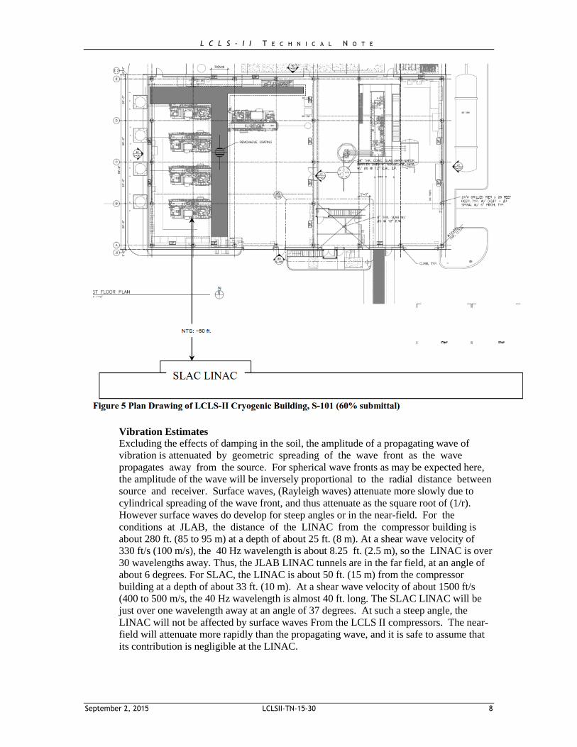
The closest portion of the SLAC LINAC will be approximately 50 ft. (15 m) from the
nearest Project helium compressor. See Figure 5.
The center of the SLAC LINAC will be about 80 ft. (24 m) from the nearest compressor
The SLAC LINAC is approximately 10 m below the ground surface.
The SLAC LINAC is founded in a sandstone formation (Whiskey Hill formation).
Geotechnical tests for the Project indicate blow counts on the order of 30 to 50 blows per
foot and higher. This is dense and stiff material, for which we expect the shear
wave velocity to be on the order of 1500 ft./s (450 to 500 m/s). This velocity is about two
to three times as fast as the shear wave velocity for the subsurface ground at JLAB.
o The vibration amplitude generated at the Project source will be
inversely proportional to \the square of shear wave velocity. Thus, the
source amplitude should be about ¼ to 1/9 as much as that at JLAB, since
similar types of equipment will be in use.
o The vibration amplitudes propagated from the compressors to the SLAC LINAC
will vary inversely with distance from the source, as assumed for the JLAB data.
The recent SLAC document authored by Gassner and Adolphson indicates that “motions
on the micron scale, which would require a significant amount of power to generate at the
frequencies of interest (above several Hz), can be tolerated.”
Cryogenic compressors will range in weight from 65,000 to 70,000 lb. ranging from 800
to 2500 horsepower capacity. Approximate base dimensions from 19 x 5 ft. to about 26 x
3 ft.
L C L S - I I T E C H N I C A L N O T E
September 2, 2015 LCLSII-TN-15-30 8
Vibration Estimates
Excluding the effects of damping in the soil, the amplitude of a propagating wave of
vibration is attenuated by geometric spreading of the wave front as the wave
propagates away from the source. For spherical wave fronts as may be expected here,
the amplitude of the wave will be inversely proportional to the radial distance between
source and receiver. Surface waves, (Rayleigh waves) attenuate more slowly due to
cylindrical spreading of the wave front, and thus attenuate as the square root of (1/r).
However surface waves do develop for steep angles or in the near-field. For the
conditions at JLAB, the distance of the LINAC from the compressor building is
about 280 ft. (85 to 95 m) at a depth of about 25 ft. (8 m). At a shear wave velocity of
330 ft/s (100 m/s), the 40 Hz wavelength is about 8.25 ft. (2.5 m), so the LINAC is over
30 wavelengths away. Thus, the JLAB LINAC tunnels are in the far field, at an angle of
about 6 degrees. For SLAC, the LINAC is about 50 ft. (15 m) from the compressor
building at a depth of about 33 ft. (10 m). At a shear wave velocity of about 1500 ft/s
(400 to 500 m/s, the 40 Hz wavelength is almost 40 ft. long. The SLAC LINAC will be
just over one wavelength away at an angle of 37 degrees. At such a steep angle, the
LINAC will not be affected by surface waves From the LCLS II compressors. The near-
field will attenuate more rapidly than the propagating wave, and it is safe to assume that
its contribution is negligible at the LINAC.
L C L S - I I T E C H N I C A L N O T E
September 2, 2015 LCLSII-TN-15-30 9
To estimate the vibration from the SLAC LCLSII cryogenic facility, we used the plotted results
and regression curves from the JLAB facility as shown in Figure 4, in which the distances were
adjusted for proximity to the nearest compressor. From these data we made adjustments for the
different soil conditions:
Amplitude reduced by a factor of 1/4 to 1/9 to account for different shear wave velocities,
and the corresponding effect on vibration transmission into the ground.
Possible decoupling effects between the LCLSII compressor building and the underlying
soil have been ignored. In particular, with the stiffer soil there may be little or
no decoupling.
Possible damping effects from JLAB data soil conditions are not included.
Possible decoupling effect between the soil and the LINAC structure have also
been ignored
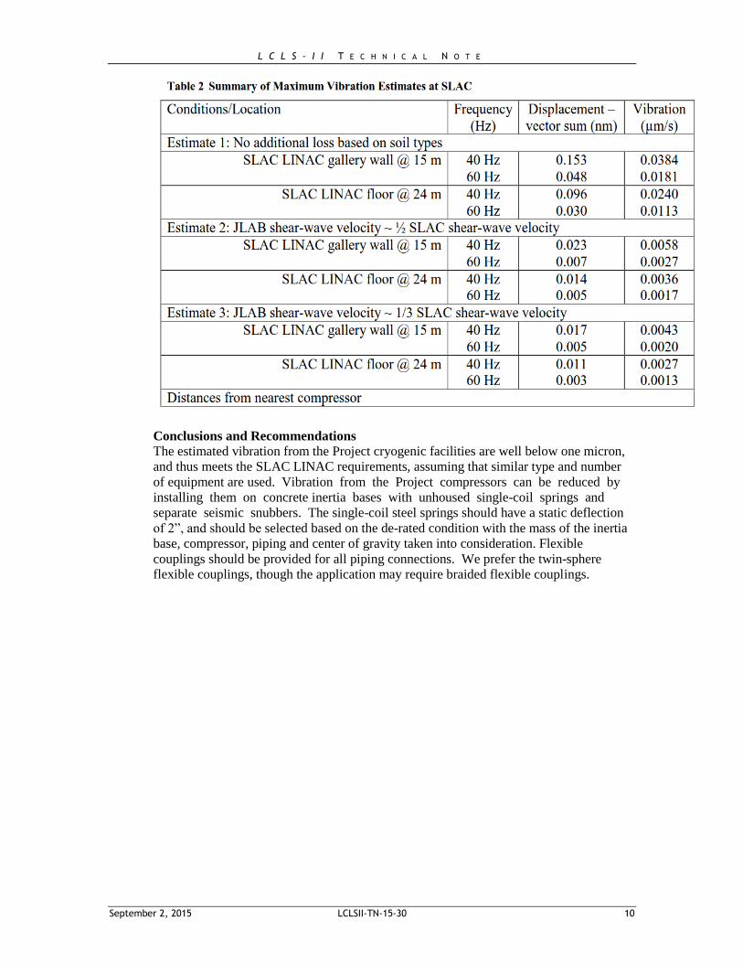
As shown in Table 2, the estimated displacement at the LINAC near gallery wall would range
from 0.017 to 0.153 nanometers at 40 Hz, well below one micron. The estimates at 60 Hz are
even lower. Thus, the expected vibration at the SLAC LINAC will be substantially lower than
what was measured at JLAB as summarized in Table 2. As shown in Table 2, vibration
displacement for all estimation methods will be less than a nanometer and well below a micron.
Therefore, no additional vibration control measures should be required.
Vibration Isolation
Vibration control measures are not necessary, as shown by the calculations in Table 2. If desired,
vibration isolation can be provided as follows:
Deeper foundation slab, on the order of 6 ft. thick throughout the compressor room could
be expected to reduce the vibration somewhat. As noted above, given the stiff soil
conditions at the Project, this effect may be small, if any. Steel-spring isolators
(approx.12) installed at load points under the skid providing a minimum 2”
deflection under loaded conditions, would reduce the vibration by a factor
of 3 to 10. All piping and conduit connections should also be resiliently connected
to control vibration transmission through the piping.
Spring-mounted inertia base would provide more rigidity for the skid and
compressor, typically with 4 to 6 springs with a minimum 2” static deflection under
loaded conditions, and would reduce the vibration by a factor of 10 to 30. All
piping and conduit connections should also be resiliently connected so that the spring
isolators are allowed to operate properly. The slab thickness should be no less than one
fifth the length or width of the slab to avoid bending wave resonances in the slab. This
may require individual inertia bases.
L C L S - I I T E C H N I C A L N O T E
September 2, 2015 LCLSII-TN-15-30 10
Conclusions and Recommendations
The estimated vibration from the Project cryogenic facilities are well below one micron,
and thus meets the SLAC LINAC requirements, assuming that similar type and number
of equipment are used. Vibration from the Project compressors can be reduced by
installing them on concrete inertia bases with unhoused single-coil springs and
separate seismic snubbers. The single-coil steel springs should have a static deflection
of 2”, and should be selected based on the de-rated condition with the mass of the inertia
base, compressor, piping and center of gravity taken into consideration. Flexible
couplings should be provided for all piping connections. We prefer the twin-sphere
flexible couplings, though the application may require braided flexible couplings.