LCC SERIES OVENS INSTRUCTION MANUAL - despatch.com C-159 Rev 11-07.pdf · The LCC series oven is a...
49
P/N 125166 REV. 11/07 C-159 LCC SERIES OVENS INSTRUCTION MANUAL Model Volts Phase Hz Heater Watts Total LCC 1-11 240 1 50/60 3,000 14.2 LCC 1-11N 240 1 50/60 3,000 14.2 LCC 1-54 240 1 50/60 6,000 26.7 LCC 1-54N 240 1 50/60 6,000 26.7 LCC 1-54NV 240 1 50/60 6,000 26.7 LCC 1-87 240 1 50/60 9,000 42.2 LCC 1-87N 240 1 50/60 9,000 42.2 LCC 1-87NV 240 1 50/60 9,000 42.2 Prepared by: Despatch Industries P.O. Box 1320 Minneapolis, MN 55420-1320 Customer Service 800-473-7373
Transcript of LCC SERIES OVENS INSTRUCTION MANUAL - despatch.com C-159 Rev 11-07.pdf · The LCC series oven is a...
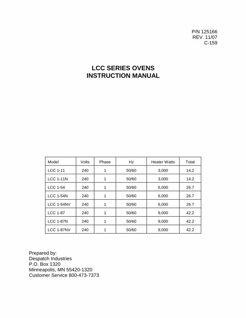
P/N 125166 REV. 11/07
C-159
LCC SERIES OVENS
INSTRUCTION MANUAL
Model
Volts
Phase
Hz
Heater Watts
Total
LCC 1-11
240
1
50/60
3,000
14.2
LCC 1-11N
240
1
50/60
3,000
14.2
LCC 1-54
240
1
50/60
6,000
26.7
LCC 1-54N
240
1
50/60
6,000
26.7
LCC 1-54NV
240
1
50/60
6,000
26.7
LCC 1-87
240
1
50/60
9,000
42.2
LCC 1-87N
240
1
50/60
9,000
42.2
LCC 1-87NV
240
1
50/60
9,000
42.2
Prepared by: Despatch Industries P.O. Box 1320 Minneapolis, MN 55420-1320 Customer Service 800-473-7373
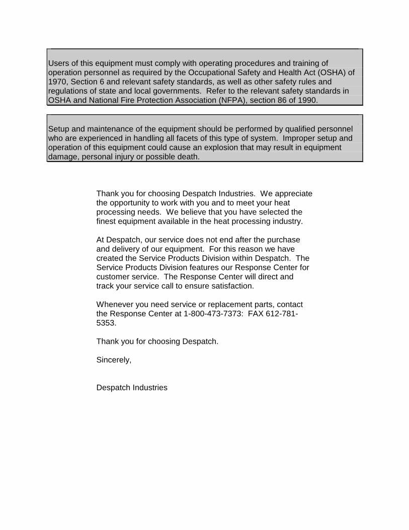
Thank you for choosing Despatch Industries. We appreciate the opportunity to work with you and to meet your heat processing needs. We believe that you have selected the finest equipment available in the heat processing industry. At Despatch, our service does not end after the purchase and delivery of our equipment. For this reason we have created the Service Products Division within Despatch. The Service Products Division features our Response Center for customer service. The Response Center will direct and track your service call to ensure satisfaction. Whenever you need service or replacement parts, contact the Response Center at 1-800-473-7373: FAX 612-781-5353. Thank you for choosing Despatch. Sincerely, Despatch Industries
Notice
Users of this equipment must comply with operating procedures and training of operation personnel as required by the Occupational Safety and Health Act (OSHA) of 1970, Section 6 and relevant safety standards, as well as other safety rules and regulations of state and local governments. Refer to the relevant safety standards in OSHA and National Fire Protection Association (NFPA), section 86 of 1990.
Caution Setup and maintenance of the equipment should be performed by qualified personnel who are experienced in handling all facets of this type of system. Improper setup and operation of this equipment could cause an explosion that may result in equipment damage, personal injury or possible death.


i
PREFACE
This manual is your guide to the Despatch oven. It is organized to give you the information you need quickly and easily. The INTRODUCTION section provides an overview of the Despatch oven. The THEORY OF OPERATION section details the function and operation of assemblies and subassem-blies on the Despatch oven. The INSTRUCTIONS section provides directions on unpacking, installing, operating and maintaining the Despatch oven. The APPENDIX section contains Special Instructions for operating the control instrument, a Troubleshoot-ing Table, and a list of Accessories. An efficient way to learn about the oven would be to read the manual while working with the corresponding oven control system. This will give you practical hands-on experience with information in the manual and the oven. Before operating the equipment, be sure you understand all of the technical information contained in this manual. Information skipped, not understood or misunderstood could create the possibility of operating the equipment in an unsafe manner. This can cause damage to the oven or personnel or reduce the efficiency of the equipment.
NOTE: Read the entire INTRODUCTION and THEORY OF OPERATION before installing the oven.
WARNING: Failure to heed warnings in this instruction manual and on the oven could result in personal injury, property damage or death.

ii

iii
TABLE OF CONTENTS
INTRODUCTION ............................................................................................................. 1
Special Features .................................................................................................. 1 SPECIFICATIONS .......................................................................................................... 2
Dimensions ........................................................................................................... 2 Capacities ............................................................................................................. 3 Power ................................................................................................................... 3 Temperature ......................................................................................................... 4
THEORY OF OPERATION ............................................................................................. 5
Construction ......................................................................................................... 6 Cooling ................................................................................................................. 6 Inert Atmosphere .................................................................................................. 6 HEPA Filters ......................................................................................................... 7
Definitions .................................................................................................. 7 Packaging and Shipping ............................................................................ 7 Handling ..................................................................................................... 8 HEPA Filter Validation Testing .................................................................. 8
D.O.P. Testing ................................................................................ 8 Class 100 Testing ........................................................................... 8 Validation Testing ........................................................................... 9
The Necessity of the Burn-off Process ...................................................... 9 Filter Unit Replacement ............................................................................ 9
CONTROL Instrument ........................................................................................ 10 HIGH LIMIT Instrument ...................................................................................... 10
Product High Limit Instrument ................................................................. 10 Oven High Limit Instrument ..................................................................... 11
INSTRUCTIONS ........................................................................................................... 12
Unpacking and Inspection .................................................................................. 12 Set-up ................................................................................................................. 13
HEPA Filter Installation ............................................................................ 15 HEPA Filter Burn-off ................................................................................ 16
OPERATING ................................................................................................................. 18
Loading the Oven ............................................................................................... 18 Pre-Startup Checklist .......................................................................................... 19 Startup ................................................................................................................ 19
Shut Down ............................................................................................... 22 Maintenance ....................................................................................................... 23
Checklist .................................................................................................. 23 Tests ................................................................................................................... 24
Nitrogen Supply Check ........................................................................... 24
iv
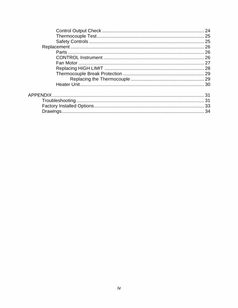
Control Output Check .............................................................................. 24 Thermocouple Test .................................................................................. 25 Safety Controls ........................................................................................ 25
Replacement ...................................................................................................... 26 Parts ........................................................................................................ 26 CONTROL Instrument ............................................................................. 26 Fan Motor ................................................................................................ 27 Replacing HIGH LIMIT ............................................................................ 28 Thermocouple Break Protection .............................................................. 29
Replacing the Thermocouple ........................................................ 29 Heater Unit ............................................................................................... 30
APPENDIX .................................................................................................................... 31
Troubleshooting .................................................................................................. 31 Factory Installed Options .................................................................................... 33 Drawings ............................................................................................................. 34

v

1
INTRODUCTION This section provides an overview of the Despatch LCC Series oven. The LCC offers HEPA filtration for processes where minimization of contamination is essential. Fresh air and nitrogen (noted with an N suffix) models are available.
Special Features The removable HEPA (High Efficiency Particulate Air) filter is designed to provide a constant flow of 99.97% clean air to the product. Other special features include:
Digital TEMP CONTROL and manual reset HIGH LIMIT to protect the chamber workload as well as the oven itself.
Stainless steel interior with all interior seams continuously welded on the insulation side to protect the work chamber from contamination and to permit chamber washing without damaging insulation.
Silicon door seals, shaft seals and gasketing (Viton Fluorocarbon on NV models).
Door seals and interior chamber walls are removable for cleaning.
Heater with a five year warranty.
Cooling coil to provide rapid cooldown and low temperature operation (nitrogen models only).
Scratch-resistant SilverClay® baked enamel exteriors and a stainless steel interior for easy cleaning.
Silicon-free construction on NV models.
Nitrogen operation (N and NV models only)
2
SPECIFICATIONS
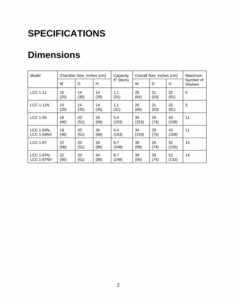
Dimensions Model
Chamber Size, inches (cm)
Capacity, ft
3 (liters)
Overall Size, inches (cm)
Maximum Number of Shelves
W
D
H
W
D
H
LCC 1-11
10 (25)
14 (35)
14 (35)
1.1 (31)
25 (64)
21 (53)
32 (81)
5
LCC 1-11N
10 (25)
14 (35)
14 (35)
1.1 (31)
26 (66)
21 (53)
32 (81)
5
LCC 1-54
18 (46)
20 (51)
26 (66)
5.4 (153)
34 (153)
29 (74)
43 (109)
11
LCC 1-54N, LCC 1-54NV
18 (46)
20 (51)
26 (66)
5.4 (153)
34 (153)
29 (74)
43 (109)
11
LCC 1-87
22 (56)
20 (51)
34 (86)
8.7 (248)
39 (99)
29 (74)
52 (132)
14
LCC 1-87N, LCC 1-87NV
22 (56)
20 (51)
34 (86)
8.7 (248)
39 (99)
29 (74)
52 (132)
14

3
Capacities Model
LCC 1-11
LCC 1-11N
LCC 1-54
LCC 1-54N, LCC 1-54NV
LCC 1-87
LCC 1-87N, LCC 1-87NV
Maximum Load
Lbs
25
25
150
150
200
200
Maximum Shelf Load
Lbs
10
10
25
25
25
25
Recirculating Fan
CFM H.P.
265 1/4
265 1/4
400 1/4
400 1/4
990 3/4
990 3/4
Approximate Net Weight
Lbs. KG
285 129
285 129
380 172
380 172
500 227
500 227
Shipping Weight (approximate)
Lbs. KG
400 181
400 181
615 279
615 279
750 341
750 341
Power Line voltages may vary in some geographical locations. If your line voltage is much lower than the oven voltage rating, warm up time will be longer and motors may overload or run hot. If your line voltage is higher than name plate rating, the motor may run hot and draw excessive amps. If the line voltage varies more than 10% from the oven voltage rating, some electrical components such as relays, temperature controls, etc. may operate erratically. Model
Volts *
Amps
Hertz
Heater Phase
KW
Cord and Plug
LCC 1-11
240
14.2
50/60
1
3
None, Hardwired
LCC 1-11N
240
14.2
50/60
1
3
None, Hardwired
LCC 1-54
240
26.7
50/60
1
6
None, Hardwired
LCC 1-54N
240
26.7
50/60
1
6
None, Hardwired
LCC 1-54NV
240
26.7
50/60
1
6
None, Hardwired
LCC 1-87
240
42.2
50/60
1
9
None, Hardwired
LCC 1-87N
240
42.2
50/60
1
9
None, Hardwired
LCC 1-87NV
240
42.2
50/60
1
9
None, Hardwired
* Oven designed for 240 volts (see nameplate on oven) will operate satisfactorily on a minimum of 208 volts, but with a 25%
reduction in heater power. If your power characteristics are lower, contact Despatch Industries.

4
Temperature Model
LCC 1-11
LCC 1-11N
LCC 1-54
LCC 1-54N, LCC 1-54V
LCC 1-87
LCC 1-87N, LCC 1-87NV
Time to Temperature (approximate minutes)
25 C -
100 C
4
4
5
5
4
4
25 C -
200 C
13
13
14
14
12
12
25 C -
260 C
20
20
23
23
18
18
Recovery Time Door Open 1 Minute (approximate minutes)
125 C
0.5
0.5
1
1
1
1
200 C
1
1
2
2
2
2
260 C
2.5
2.5
3
3
3
3
Temperature Uniformity at (maximum)
125 C
± 1 C
± 1 C
± 2 C
± 2 C
± 1 C
± 1 C
200 C
± 2 C
± 2 C
± 2 C
± 2 C
± 2 C
± 2 C
260 C
± 3 C
± 3 C
± 3 C
± 3 C
± 3 C
± 3 C
Maximum Operating Temperature
260 C
260 C
260 C
260 C
260 C
260 C
Minimum Operating Temperature Above Ambient (approximate)
Without Water Cooling
48 C
53 C
34 C
85 C
54 C
116 C
With Water Cooling
9 C
9 C
18 C
18 C
35 C
40 C
Cooling Time Empty Oven (approximate minutes)
200 C -
50 C
63
64
48
58
54
78
Control Stability
± 0.3 C
± 0.3 C
± 0.3 C
± 0.3 C
± 0.3 C
± 0.3 C
Repeatability
± 0.5 C
± 0.5 C
± 0.5 C
± 0.5 C
± 0.5 C
± 0.5 C
5
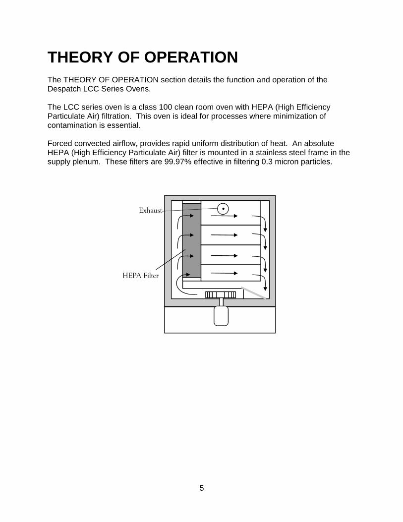
THEORY OF OPERATION The THEORY OF OPERATION section details the function and operation of the Despatch LCC Series Ovens. The LCC series oven is a class 100 clean room oven with HEPA (High Efficiency Particulate Air) filtration. This oven is ideal for processes where minimization of contamination is essential. Forced convected airflow, provides rapid uniform distribution of heat. An absolute HEPA (High Efficiency Particulate Air) filter is mounted in a stainless steel frame in the supply plenum. These filters are 99.97% effective in filtering 0.3 micron particles.

6
Construction The LCC series oven has a type 304-2B stainless steel interior. All interior seams are continuously welded on the insulation side. This protects the work chamber from contaminated air and permits chamber washing without damaging the insulation. Interior chamber walls and silicon door gaskets (Viton Fluorocarbon on NV models) can be easily removed for cleaning. Heater frame, fan wheel and motor shaft are constructed of stainless steel.
Exteriors are steel finished in SilverClay enamel, baked to a 2H hardness for chip and scratch resistance. All controls are mounted on the front of the oven for easy operation and readability. Two electropolished stainless steel wire shelves are provided. The shelves are removable and adjustable on two inch centers.
Cooling Air models have an adjustable fresh air damper which allows cooling of the oven. Nitrogen models have a stainless steel water coil. When used in conjunction with the optional flowmeter the cooling coil permits rapid cooldown and low temperature operation.
Inert Atmosphere An inert atmosphere option offers the advantages of both a clean room oven and inert atmosphere oven. The nitrogen portion for the LCC series oven includes a manual three way valve and two flowmeters, connected by piping to the inlet connection on the lower back panel marked nitrogen supply.

7
HEPA Filters Absolute HEPA (High Efficiency Particulate Air) filters are used to limit particulate size in the work chamber to 0.3 microns or less. The gentle entrance and exit air velocity to and from the HEPA filter results in high efficiency and long life for the HEPA filters.
Definitions HEPA - High Efficiency Particulate Air Burn-Off - A process for getting rid of the binder and D.O.P. contained in the filter from the manufacturing and testing function. D.O.P. - Dioctyl Phthalate - Aerosol particles of submicron size used in the testing phase to spot defects or measure filter efficiency. Binder - An organic substance that is used in the construction of the filter that gives some structural strength to the media.
Packaging and Shipping Packaging practice varies among the filter unit manufacturers. Normally units are packaged in cardboard cartons with various approaches for internal strengthening and impact-resistance of the container. The shipping carton normally is marked with a vertical arrow and "This Side Up". A filter unit is placed in the carton so that the pleated folds are vertical (running from top to bottom - not side to side). Filters should be shipped, handled and stored with the pleats in the vertical position. If shipped with the pleats in the horizontal position, the filter medium may break at the adhesive line. If handled or stored with the pleats in the horizontal position the pleats may sag. Moreover, the filter unit should be installed with the pleats in the vertical position. When installed in the horizontal position the pleats form shelves for the collection of entrapped material. The accumulated weight of this material causes sagging and leads to an early failure of the unit.
NOTE: Chamber temperature transitions must not
exceed 1.5 C/minute in order to maintain class 100 chamber conditions. Optional
filter is available for transition rates up to 5 C/minute. Consult the factory.

8
Handling The filter is shipped in the original carton or package that the filter manufacturer uses. This will give good storage and maximum protection from dirt and moisture. HEPA filters should be stored and moved in the shipping carton with in the upright position. Handling should be kept to a minimum. During installation the filter should be removed from the shipping carton and installed directly into the oven. If for any reason an unpackaged filter unit must be placed with its face on the floor or other surface, the surface must be cleared of every object or irregularity which might damage the filter pack.
HEPA Filter Validation Testing This section describes the Despatch position and recommendations for HEPA filter testing and oven validation procedures. Despatch guarantees that the filters will meet specified efficiency ratings when the filter is:
properly installed
run at or below 200 C, at a constant temperature
run before burn-in
D.O.P. Testing In D.O.P. testing aerosol particles of submicron size are used to spot defects or measure filter efficiency. Degenerative by-products of this test are distributed throughout the oven chamber upon heat-up. Therefore Despatch does not recommend D.O.P. filter testing.
Class 100 Testing Despatch guarantees the environment within the oven to be Class 100. This classification is based upon measurement of the particulate level within the oven work chamber. Class 100 testing may be performed before or after a proper filter burn-in procedure has been performed. Despatch will guarantee Class 100 conditions measurements based on two methods of test. The direct method of test employs an extraction type particulate analyzer. The indirect method involves particle settling over a specified
9
period of time onto a clean disk.
Validation Testing Based on the issues discussed in this section, Despatch recommends the following test sequence for pharmaceutical Class 100 ovens. 1. Proper installation of the HEPA filters. 2. Cold D.O.P. challenge to determine integrity of oven chamber and filter gaskets. 3. Proper filter burn-off procedure. 4. Class 100 testing inside the work chamber.
The Necessity of the Burn-off Process HEPA filters contain a binder material which protects the filter media during production and shipping. This smoke is typically not desirable during normal operation of the oven. Burning off the binder will ensure a clean process at elevated temperatures. When the binder is burned out of the filter media, the filter becomes very fragile, too fragile to withstand normal shipping and handling. For this reason, Despatch does not perform the burn-off procedure.
Filter Unit Replacement Replacement of the filter unit will be necessary for various reasons.
Resistance, or pressure drop, across the filter unit. Maximum level of resistance in inches (water gauge) will vary depending upon the operation of the filter and the available fan capacity. Adequate fan capacity must be available.
Loss of efficiency (leakage), determined from air-sampling measurements made downstream of the filter unit.
Visible damage or rupture of the filter media in a unit.
Change in process application.
Excessive build-up of lint or combustible particulate matter on the filter unit.

10
Water droplets in airstream through filter, free water (RH = 100%), will saturate filter very quickly and may cause burnout or holes in burned off filter media.
High level of radiation in the vicinity of the filter unit.
CONTROL Instrument The CONTROL instrument operates the heating element in response to the entered temperature setpoint. It provides digital indication of the setpoint and actual oven temperature. Please refer to the operator’s manual for the CONTROL instrument provided with the oven, for detailed operating instructions.
HIGH LIMIT Instrument The purpose of the HIGH LIMIT instrument is to protect the product and/or the oven from excessively high temperatures. If the setting on the HIGH LIMIT is exceeded, the heating process will discontinue. The HIGH LIMIT instrument must be set to a temperature slightly higher than the CONTROL instrument setpoint or to a temperature that should not be exceeded in the process. The instrument must be manually reset by pushing the red button.
Product High Limit
Instrument If the product being processed has a critical high temperature limit, the HIGH LIMIT instrument should be used as a product high limit instrument. The HIGH LIMIT instrument should be set to a temperature somewhat below the temperature at which the product could be damaged. Use the CONTROL instrument or a pyrometer to determine the product setting. If the destructive temperature of the product is already known, this could be used as a point below which the product HIGH LIMIT is set.
NOTE:
Despatch Industries cannot be responsible for either the process, the process temperature used, or for the quality of the product being processed. It is the responsibility of the purchaser and operator to see that the product undergoing processing in a Despatch oven is adequately protected from damage. Carefully following the instructions in this manual will assist the purchaser and operator in fulfilling that responsibility.

11
Oven High Limit Instrument If the product does not have a critical high temperature limit, the HIGH LIMIT can be used as an oven HIGH LIMIT instrument. An oven HIGH LIMIT instrument protects oven equipment. Since the HIGH LIMIT instrument does not show the temperature, it can be properly set only after oven is in operation. Until then, the HIGH LIMIT should be set at maximum position so all preliminary testing and adjusting can be done. Never operate the oven at a temperature in excess of the maximum operating
temperature of 260 C (500 F).
12
INSTRUCTIONS The INSTRUCTIONS section provides directions on unpacking, installation, operation and maintenance of the Despatch LCC Series Ovens.
Unpacking and Inspection Remove all packing materials and thoroughly inspect the oven for damage of any kind that could have occurred during shipment.
See whether the carton and plastic cover sheet inside carton are still in good condition.
Look at all outside surfaces and corners of the oven for scratches and dents.
Check the oven controls and indicators for normal movement, bent shafts, cracks, chips or missing parts such as knobs and lenses.
Check the door and latch for smooth operation.
Check the filter carton for damage. If there is damage that could have happened during shipment follow these instructions: 1. Contact the shipper immediately and file a written damage claim. 2. Contact Despatch Industries to report your findings and to order replacement
parts for those that were damaged or missing. 3. Please send a copy of your filed damage claims to Despatch. 4. Check to make sure you have received all the required materials. Your shipment
should include:
One (1) Despatch oven,
One (1) Filter,
One (1) oven instruction manual,
One (1) control instrument instruction manual,
One (1) high limit instrument manual,
One (1) Warranty card,
Two (2) Shelves
One (1) Package containing four rubber pads If any of these items are missing from the packaged contents, contact Despatch

13
Industries to have the appropriate materials forwarded to you. Any optional accessories ordered will be shipped separately.
5. Complete the warranty card and mail it to Despatch within 15 days after receipt
of the equipment.
Set-up 1. Remove adhesive backing sheet from the rubber pads. 2. Attach rubber pads to the bottom corners of the oven. 3. Place oven on a bench top or an optional
cabinet base. The oven must have a minimum of two (2) inches clearance in the rear to provide proper ventilation. The oven may be placed next to another cabinet, or next to another oven, with three-quarters (¾) of an inch clearance (the doors are still open).
4. Make sure oven is level and plumb; this will assure proper heat distribution and
operation of all mechanical components. 5. (Nitrogen models only) Connect the
nitrogen supply line (from your plant nitrogen system) to the inlet marked nitrogen supply on the oven rear panel. The nitrogen supply to the oven must not exceed 40 PSI.
6. (Nitrogen models only) Install water
connection for cooling coils.
a. Pipe the coil with a three-way water supply/drain valve on the inlet (bottom fitting) and a vacuum breaker valve at the high point of the drain line. This will keep water moving through the cooling coil, minimizing steam generation. The water supply to the oven must not exceed 100 PSI.
b. Mount the optional cooling water flowmeter (included in cooling kit part
number 090020.)
WARNING: DO NOT use oven in wet, corrosive, or explosive atmosphere.
WARNING: DO NOT use with other than inert gases (nitrogen model only).
CAUTION: The design and piping of the drain system should preclude the possibility of operator injury from high temperature or pressure buildup. Piping must be able to withstand
short periods of up to 450 temperatures. Drain lines should be insulated or warning labels installed for the distance that a hazard exists.
14
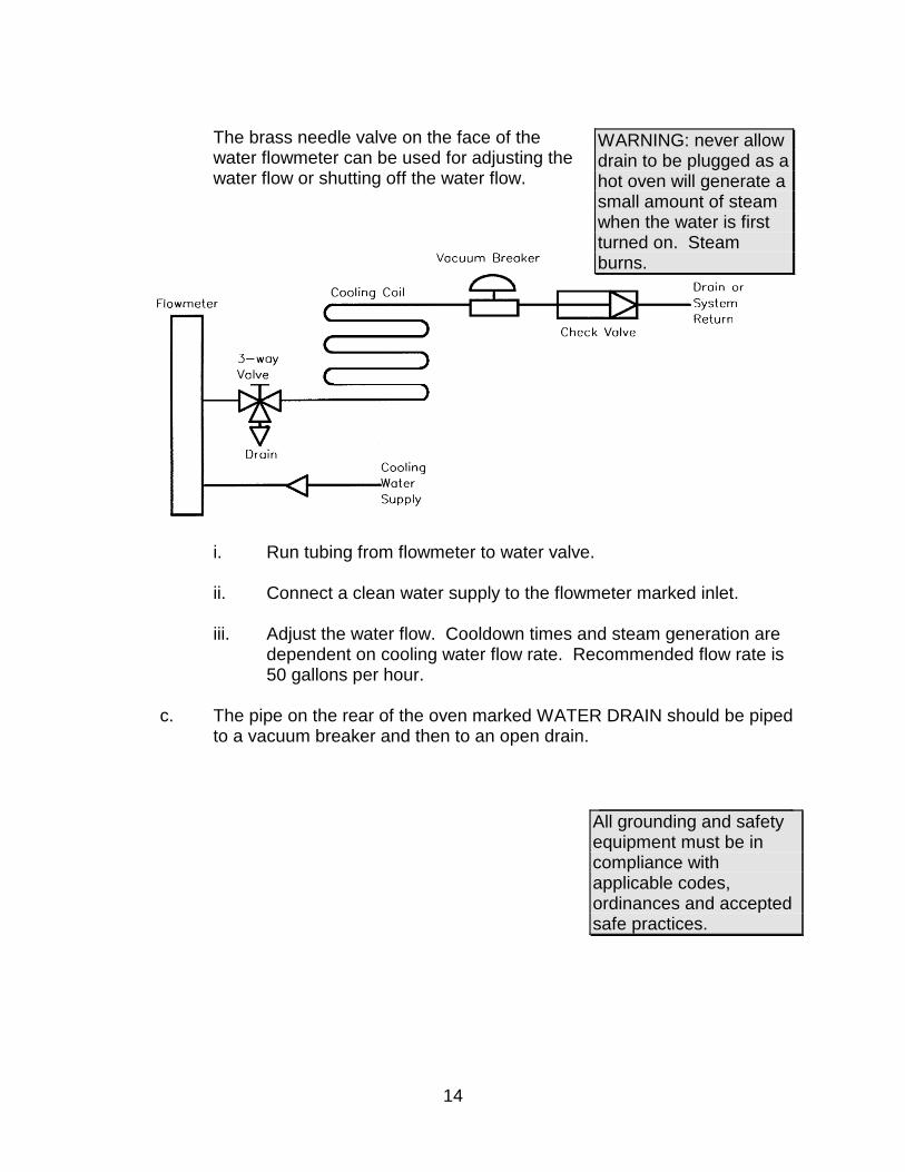
The brass needle valve on the face of the water flowmeter can be used for adjusting the water flow or shutting off the water flow.
i. Run tubing from flowmeter to water valve.
ii. Connect a clean water supply to the flowmeter marked inlet.
iii. Adjust the water flow. Cooldown times and steam generation are dependent on cooling water flow rate. Recommended flow rate is 50 gallons per hour.
c. The pipe on the rear of the oven marked WATER DRAIN should be piped
to a vacuum breaker and then to an open drain.
WARNING: never allow drain to be plugged as a hot oven will generate a small amount of steam when the water is first turned on. Steam burns.
WARNING: All grounding and safety equipment must be in compliance with applicable codes, ordinances and accepted safe practices.
15
7. Identify correct power source indicated on the specification plate. Power requirements are also listed on the cover of this manual.
8. Hardwire oven directly to a disconnect switch and wire the disconnect switch
directly to the electric supply. Refer to the electrical schematic in the back of this manual and the power requirements table in the Specifications section.
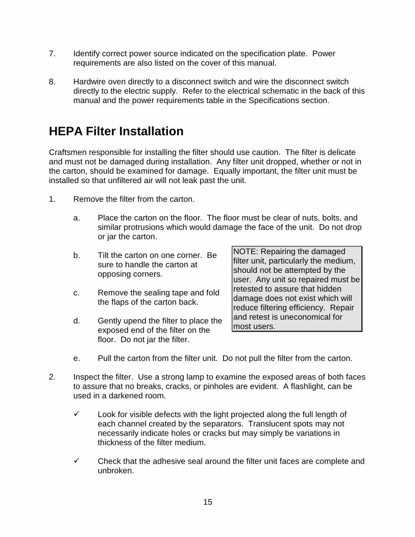
HEPA Filter Installation Craftsmen responsible for installing the filter should use caution. The filter is delicate and must not be damaged during installation. Any filter unit dropped, whether or not in the carton, should be examined for damage. Equally important, the filter unit must be installed so that unfiltered air will not leak past the unit. 1. Remove the filter from the carton.
a. Place the carton on the floor. The floor must be clear of nuts, bolts, and similar protrusions which would damage the face of the unit. Do not drop or jar the carton.
b. Tilt the carton on one corner. Be
sure to handle the carton at opposing corners.
c. Remove the sealing tape and fold
the flaps of the carton back.
d. Gently upend the filter to place the exposed end of the filter on the floor. Do not jar the filter.
e. Pull the carton from the filter unit. Do not pull the filter from the carton.
2. Inspect the filter. Use a strong lamp to examine the exposed areas of both faces
to assure that no breaks, cracks, or pinholes are evident. A flashlight, can be used in a darkened room.
Look for visible defects with the light projected along the full length of
each channel created by the separators. Translucent spots may not necessarily indicate holes or cracks but may simply be variations in thickness of the filter medium.
Check that the adhesive seal around the filter unit faces are complete and
unbroken.
NOTE: Repairing the damaged filter unit, particularly the medium, should not be attempted by the user. Any unit so repaired must be retested to assure that hidden damage does not exist which will reduce filtering efficiency. Repair and retest is uneconomical for most users.
16
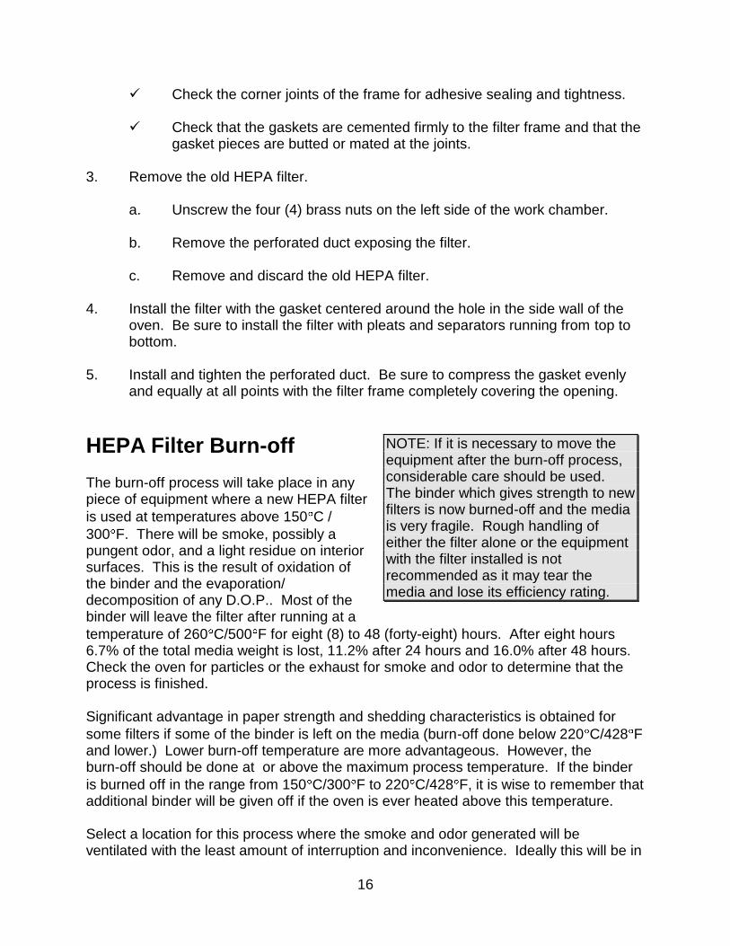
Check the corner joints of the frame for adhesive sealing and tightness.
Check that the gaskets are cemented firmly to the filter frame and that the gasket pieces are butted or mated at the joints.
3. Remove the old HEPA filter.
a. Unscrew the four (4) brass nuts on the left side of the work chamber.
b. Remove the perforated duct exposing the filter.
c. Remove and discard the old HEPA filter. 4. Install the filter with the gasket centered around the hole in the side wall of the
oven. Be sure to install the filter with pleats and separators running from top to bottom.
5. Install and tighten the perforated duct. Be sure to compress the gasket evenly
and equally at all points with the filter frame completely covering the opening.
HEPA Filter Burn-off The burn-off process will take place in any piece of equipment where a new HEPA filter
is used at temperatures above 150 C /
300 F. There will be smoke, possibly a pungent odor, and a light residue on interior surfaces. This is the result of oxidation of the binder and the evaporation/ decomposition of any D.O.P.. Most of the binder will leave the filter after running at a
temperature of 260 C/500 F for eight (8) to 48 (forty-eight) hours. After eight hours 6.7% of the total media weight is lost, 11.2% after 24 hours and 16.0% after 48 hours. Check the oven for particles or the exhaust for smoke and odor to determine that the process is finished. Significant advantage in paper strength and shedding characteristics is obtained for
some filters if some of the binder is left on the media (burn-off done below 220 C/428 F and lower.) Lower burn-off temperature are more advantageous. However, the burn-off should be done at or above the maximum process temperature. If the binder
is burned off in the range from 150 C/300 F to 220 C/428 F, it is wise to remember that additional binder will be given off if the oven is ever heated above this temperature. Select a location for this process where the smoke and odor generated will be ventilated with the least amount of interruption and inconvenience. Ideally this will be in
NOTE: If it is necessary to move the equipment after the burn-off process, considerable care should be used. The binder which gives strength to new filters is now burned-off and the media is very fragile. Rough handling of either the filter alone or the equipment with the filter installed is not recommended as it may tear the media and lose its efficiency rating.
17
the final location for the oven. However, it may be a receiving dock, some well ventilated space or even outside if the weather is acceptable. If this location is a very clean area, then special attention must be given to an exhaust hook-up that will capture the smoke and odor. The following procedure is recommended: 1. Locate the equipment exhaust opening where chamber air is being expelled.
If the oven filter is burned off in a clean area, be sure to handle the equipment exhaust appropriately. If the equipment is large and the exhaust stack is a permanent service connection, it should be connected before the burn-off process is run. If the equipment is small with no permanent exhaust duct required, arrange a temporary connection out of the clean area that will handle the maximum temperature of the equipment. Direct the smoke and odor outside, or to a highly ventilated area.
2. Filters for 260 C/500 F and below: Set the temperature control at the maximum process temperature.
Filters for above 260 C/500 F: To maximize the life of the filter, set the control to
ramp the oven temperature at 1 C (1.8 F) per minute or slower. Program a 3
hour soak at 75 C/167 F, and a 3.5 hour soak at 105 C/220 F during the first heating ramp. The limited ramp rate and soaks will cure the ceramic adhesive in these filters for maximum strength.
3. Start the fan after making the electrical power connections. 4. Energize the equipment heater.
Use enough fresh air or purge nitrogen to remove the smoke, while still being able to achieve and maintain the necessary temperature. The completion of the burn-off period should be based on the particle level in the oven or smoke-free exhaust and minimal odor level.
The filter hold-down nuts should be checked after burn-off and tightened again if necessary. For best oven particle control, this step should be repeated on a regular basis.
18
OPERATING Users and operators of this oven must comply with operating procedures and training of operating personnel as required by the Occupational Safety and Health Act (OSHA) of 1970, Section 5 and relevant safety standards, and other safety rules and regulations of state and local governments. Refer to the relevant safety standards in OSHA and National Fire Protection Association (NFPA), Section 86 of 1990.
Loading the Oven Despatch Industries cannot be responsible for either the process or process temperature used, or for the quality of the product being processed. It is the responsibility of the purchaser and operator to see that the product undergoing processing in a Despatch oven is adequately protected from damage. Carefully following the instructions in this manual will help the purchaser and operator in fulfilling that responsibility. When loading the oven avoid spills of anything onto the heater elements or onto the floor of the oven. Do not place the load on the oven floor plate. This may cause the load to heat unevenly and the weight may cause shorting out of the heater elements. Use the shelves provided. The two shelves are designed to be pulled out about half way without tipping. The support capacity of the shelves is listed in the Capacities Table in the Specifications section in this manual. Do not overload the shelves. Distribute the workload evenly so that airflow is not restricted. Do not overfill your oven. The workload should not take up more than two-thirds of any dimension of the inside cavity.
19
Pre-Startup Checklist Know the system. Read this manual carefully. Make use of its instructions and
explanations. The know how of safe, continuous, satisfactory, trouble-free operation depends primarily on the degree of your understanding of the system and of your willingness to keep all parts in proper operating condition.
Check line voltage. This must correspond to nameplate requirements of motors
and controls. A wrong voltage can result in serious damage. Refer to the section on power connections in the INTRODUCTION of this manual.
Check fresh air & exhaust dampers (Non-atmosphere models only). Do not be
careless about restrictions in and around the fresh air and exhaust openings and stacks. Under no condition, permit them to become so filled with dirt that they reduce airflow.
Startup For fastest oven heat-up time, close the vent (fresh air models). After desired temperature is reached, vent may be adjusted as needed. 1. Start fan.
a. Open oven door.
b. Press POWER toggle switch to the ON position. You will hear the recirculating fan start.
c. Shut oven door.
d. Check that the amber LED on the CONTROL panel is on.
2. Enter setpoint on the CONTROL instrument.
3. Set HIGH LIMIT instrument to a temperature 10 C - 15 C higher than the setpoint or to a temperature that should not be exceeded in the process. It will be necessary to reset the HIGH LIMIT instrument whenever it has tripped. To reset, allow the oven to cool slightly or increase the HIGH LIMIT setpoint above the actual temperature. Press the RESET button.
WARNINGS: Do not use any flammable solvent or other flammable material in this oven. Do not process closed containers of any substance or liquid in this oven because they may explode under heat.
WARNING: DO NOT touch cooling coil drain piping during chamber operation - steam can be generated in the cooling coil and STEAM BURNS.

20
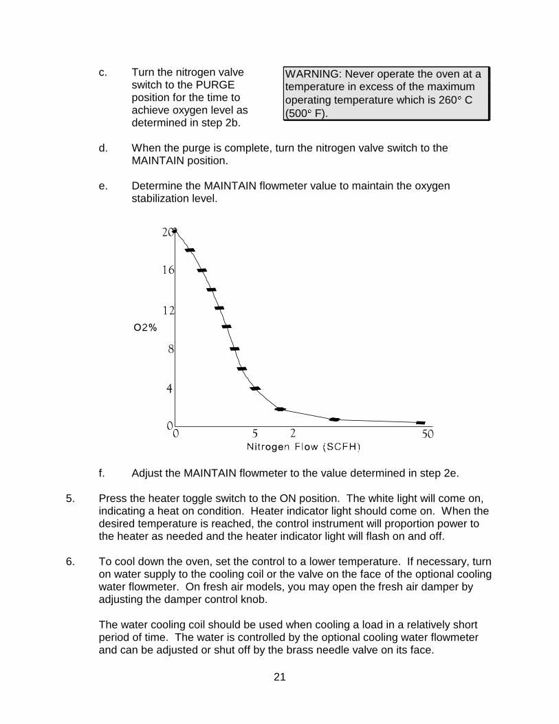
4. For the inert atmosphere ovens, adjust flow rate.
a. Determine the desired
oxygen level.
b. Use the following chart to determine the time to achieve the desired oxygen level.
NOTE: When operating the oven without the optional water cooling, the minimum operating temperature is approximately
78 C (nitrogen models) and
approximately 20 C (non-nitrogen models) over the ambient room temperature. This is the result of the heat generated by the recirculating fan.
NOTE: This graph is an approximate measure. Actual conditions will vary. The grade of the inlet gas used will also affect performance.
21
c. Turn the nitrogen valve switch to the PURGE position for the time to achieve oxygen level as determined in step 2b.
d. When the purge is complete, turn the nitrogen valve switch to the
MAINTAIN position.
e. Determine the MAINTAIN flowmeter value to maintain the oxygen stabilization level.
f. Adjust the MAINTAIN flowmeter to the value determined in step 2e.
5. Press the heater toggle switch to the ON position. The white light will come on,
indicating a heat on condition. Heater indicator light should come on. When the desired temperature is reached, the control instrument will proportion power to the heater as needed and the heater indicator light will flash on and off.
6. To cool down the oven, set the control to a lower temperature. If necessary, turn
on water supply to the cooling coil or the valve on the face of the optional cooling water flowmeter. On fresh air models, you may open the fresh air damper by adjusting the damper control knob.
The water cooling coil should be used when cooling a load in a relatively short period of time. The water is controlled by the optional cooling water flowmeter and can be adjusted or shut off by the brass needle valve on its face.
WARNING: Never operate the oven at a temperature in excess of the maximum
operating temperature which is 260 C
(500 F).
WARNING: Never operate the oven at a temperature in excess of the maximum
operating temperature which is 260 C
(500 F).
22
7. After heating cycle is complete, turn the heater toggle switch to the OFF position.
Do not turn the power off until the oven chamber temperature is below 100 C
(212 F).
Shut Down 1. Push the heater switch to OFF after the heating cycle is complete.
2. Do not turn the power off until the oven temperature is below 150 C (302 F). If the oven is turned off before it is properly cooled, the fan shaft and motor bearings may become overheated, shortening the life of the motor.
3. Turn the nitrogen control valve to OFF (nitrogen models). 4. Turn off the water supply to the cooling coil or the valve on the face of the
optional cooling water flowmeter (nitrogen models). 5. Push the POWER switch to OFF.
23
Maintenance Do not attempt any service on this oven before opening the main power disconnect switch.
Checklist
Keep equipment clean. Gradual dirt accumulation retards air flow. A dirty oven can result in unsatisfactory operation such as unbalanced temperature in the work chamber, reduced heating capacity, reduced production, overheated components, etc. Keep the walls, floor and ceiling of the oven work chamber free of dirt and dust. Floating dust or accumulated dirt may produce unsatisfactory work results. Keep all equipment accessible. Do not permit other materials to be stored or piled against it.
Protect controls against excessive heat. This is particularly true of controls, motors or other equipment containing electronic components. Temperatures
greater than 51.5 C (125 F) should be avoided.
Establish maintenance & checkup schedules. Do this promptly and follow the schedules faithfully. Careful operation and maintenance will be more than paid for in continuous, safe and economical operation.
Maintain equipment in good repair. Make repairs immediately. Delays may be costly in added expense for labor and materials and in prolonged shut down.
Practice safety. Make it a prime policy to know what you are doing before you do it. Make CAUTION, PATIENCE, and GOOD JUDGEMENT the safety watchwords for the operation of your oven.
Lubrication, Fan motor bearings are permanently lubricated. All door latches, hinges, door operating mechanisms, bearing or wear surfaces should be lubricated to ensure easy operation.
24
Tests Tests should be performed carefully and regularly. The safety of personnel as well as the condition of equipment may depend upon the proper operation of any one of these controls at any time.
Nitrogen Supply Check This test is necessary in nitrogen models only. 1. Turn the inert atmosphere valve on
the control panel to the OFF position.
2. Screw the adjusting knob on the
flowmeters clockwise all the way to the OFF position. The adjusting knobs must be off on both the PURGE and MAINTAIN flowmeters.
3. Open the tank valve on the nitrogen supply and set the pressure regulator to
about 40 psi. 4. Check the nitrogen plumbing for leaks using a soapy water solution. As nitrogen
gas is odorless, all leaks should be stopped to prevent the possibility of suffocation in a small work area in which a nitrogen leak might displace much of the oxygen in the atmosphere.
Control Output Check
1. On a cool oven (< 100 C or 212 F), adjust CONTROL setpoint to 20 F (11 C) higher than current actual chamber temperature.
2. Set HEATER switch to ON. 3. When the CONTROL output indicator light is on, the HEATER indicator should
also be on. 4. When the CONTROL output indicator light turns off, the HEATER indicator light
should also turn off. If the HEATER light remains on, the SSR may be shorted. You can also verify the CONTROL output by measuring across the output (+ and -) terminals with a voltage meter. The output should measure >4 VDC when on,
WARNING: High voltage is present on terminals, voltage checks should be made only by qualified electrical maintenance personnel: e.g. electrician or technician. Failure to heed this warning can result in serious bodily injury, property damage, or death.
25
and < 1 VDC when off. 5. Reconnect line power to the control. 6. Replace the SSR if shorted or replace the CONTROL instrument if the output
does not measure properly.
Thermocouple Test 1. Place a jumper or short the thermocouple terminals on the control. The display
should read ambient temperature and be very stable. 2. Replace the CONTROL if the unit is not stable.
Safety Controls Make these tests carefully and do them regularly. The safety of personnel as well as the equipment may depend upon the proper operation of any one of these controls at any time. Temperature Control (every 40 hours) - The heater indicator light should flash every 1 to 2 seconds when the control is operating at a steady set point temperature. HIGH LIMIT (every 40 hours) - With the oven operating at a given temperature, gradually lower the high limit setpoint to the setpoint operating temperature. Verify that the HIGH LIMIT trips (heater indicator will turn off and remain off). Return the HIGH LIMIT to its original setting and press the high limit reset button.

26
Replacement
Parts To return parts contact Despatch Industries to obtain an MRA (material return authorization) number. This number must be attached to the returned part for our identification. If required, a new part will be sent and invoiced to you. When the return part is received, credit will be given, if in warranty. When ordering parts or service, be sure to specify the model, serial number and part number. This will expedite the process of obtaining your replacement part.
CONTROL Instrument (Tools needed: one quarter (¼) inch socket set) 1. Disconnect power. 2. Remove screws from the face of the control panel and slide it forward. 3. Remove wires from the old control, noting which numbered wires connect to
which terminals. 4. Replace old control with new control. 5. Reattach wires to the new CONTROL instrument. Make sure that the wires are
connected correctly. Refer to the wiring diagram in the appendix of this manual. 6. Replace control panel.
WARNING: Shut down nitrogen supply and disconnect main power switch or power cord before attempting any repairs or adjustments.

27
Fan Motor (Tools needed: Screwdriver, Allen wrench, crescent wrench) 1. Disconnect power. 2. Remove filter cover and filter from left side. 3. Remove floor plate.
a. Remove screws from the floor plate.
b. Lift floor plate out of the oven. 4. Remove the screws from the heater frame then tip up and to the right. 5. Loosen set screws on fan wheel inside fan housing. 6. Remove the screws from the face of the control panel and slide it forward to
uncover motor. 7. Tip oven on its back. 8. Remove outside floor. 9. Unbolt the four bolts holding the motor to the motor mount. 10. Remove motor. After fan wheel has run at temperature for a while it will stick to
the shaft. Some force may be required to separate the two. Suggest holding the fan wheel against the insulated wall while using a mallet and center punch to loosen the shaft from the fan.
11. Disconnect motor leads from terminal block. 12. Hold new motor in place while you remount fan wheel to motor shaft. Reattach
motor to motor mount. 13. Attach motor lead wires to terminal block (see wiring diagram). 14. Replace oven control panel and bottom, then tip oven upright again. 15. Adjust fan wheel for 3/16 inch clearance between wheel and inlet ring.

28
16. Tighten set screws making sure set screws hit the flats machined into the motor shaft.
17. Bolt heater back in place. 18. Replace interior floor. 19. Replace filter and filter cover. 20. Reconnect power.
Replacing HIGH LIMIT (Tools needed: Screwdriver, one quarter (¼) inch socket set) 1. Disconnect power. 2. Remove screws from face of control panel and slide it forward. 3. Remove wires from HIGH LIMIT noting which numbered wires connect to which
terminals. Refer to wiring diagram in this manual. 4. Replace old HIGH LIMIT with new HIGH LIMIT. 5. Reattach wires to the new HIGH LIMIT. Make sure the wires are connected
correctly. 6. Replace control panel.
29
Thermocouple Break Protection If the thermocouple breaks, the control instrument will shut off power to the heater, preventing excessive temperature in the chamber.
Replacing the Thermocouple (Tools needed: Small screwdriver and small crescent wrench) The controller thermocouple is type J (iron/constantan) and is replaceable using the following procedure: 1. Disconnect power and remove screws from the face of the control panel and
slide it forward. 2. Locate thermocouple along the left side of the control chamber. 3. Loosen the nut on the fitting holding the thermocouple in place. 4. Pull thermocouple out of brass fitting. 5. Feed new thermocouple through the nut and ferrule and place back into the
fitting. 6. Re-tighten the fitting nut. 7. Remove old thermocouple from terminals on the CONTROL and HIGH LIMIT
instruments. 8. Attach new thermocouple leads to the proper terminals of the CONTROL and
HIGH LIMIT instruments. 9. Replace oven control panel.
30
Heater Unit (Tools needed: Crescent wrench, screwdriver, one quarter (¼) inch socket set) 1. Disconnect power. 2. Remove filter cover and filter from left side. 3. Remove floor plate.
a. Remove screws from the floor plate.
b. Lift floor plate out of the oven. 4. Disconnect heater leads from heater element with wrench. Note which wires go
on which terminals. 5. Unscrew screws holding the frame to the oven body. 6. Remove heater and discard. 7. Screw down new heater frame. 8. Attach heater leads to appropriate terminals. 9. Replace interior floor and screws. 10. Replace filter and filter cover. 11. Reconnect power.
31
APPENDIX
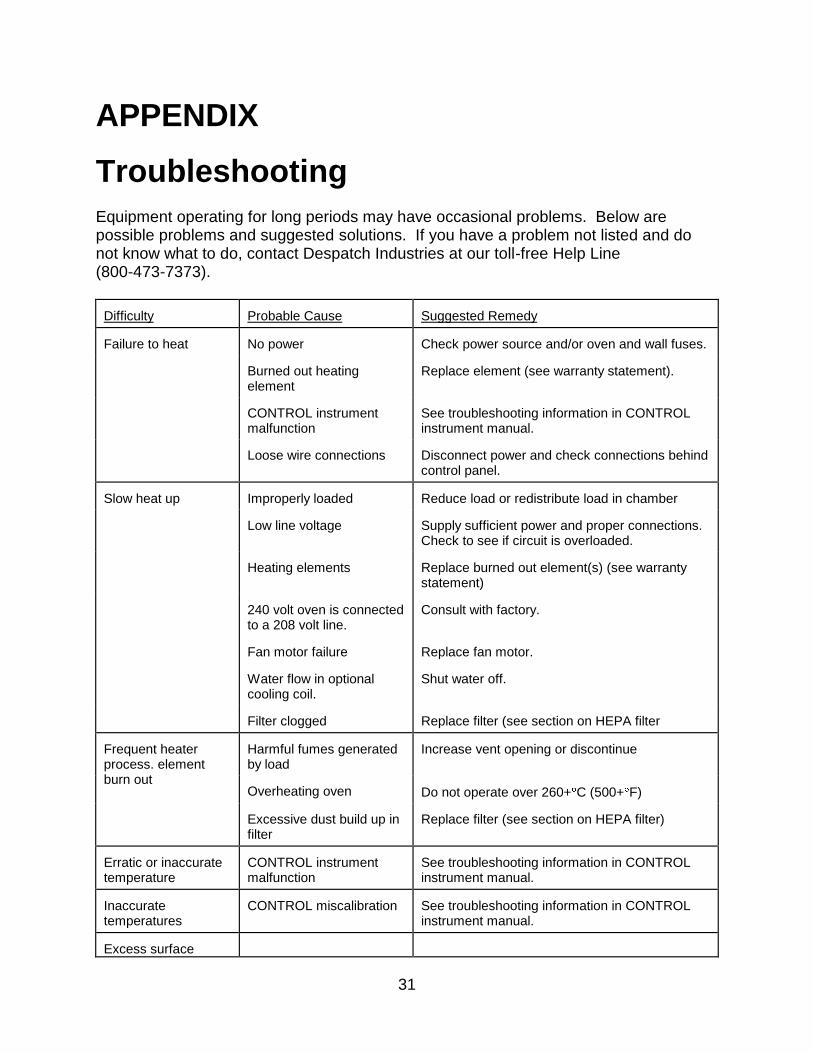
Troubleshooting Equipment operating for long periods may have occasional problems. Below are possible problems and suggested solutions. If you have a problem not listed and do not know what to do, contact Despatch Industries at our toll-free Help Line (800-473-7373). Difficulty
Probable Cause
Suggested Remedy
Failure to heat
No power
Check power source and/or oven and wall fuses.
Burned out heating element
Replace element (see warranty statement).
CONTROL instrument malfunction
See troubleshooting information in CONTROL instrument manual.
Loose wire connections
Disconnect power and check connections behind control panel.
Slow heat up
Improperly loaded
Reduce load or redistribute load in chamber
Low line voltage
Supply sufficient power and proper connections. Check to see if circuit is overloaded.
Heating elements
Replace burned out element(s) (see warranty statement)
240 volt oven is connected to a 208 volt line.
Consult with factory.
Fan motor failure
Replace fan motor.
Water flow in optional cooling coil.
Shut water off.
Filter clogged
Replace filter (see section on HEPA filter
Frequent heater process. element burn out
Harmful fumes generated by load
Increase vent opening or discontinue
Overheating oven
Do not operate over 260+ C (500+ F)
Excessive dust build up in filter
Replace filter (see section on HEPA filter)
Erratic or inaccurate temperature
CONTROL instrument malfunction
See troubleshooting information in CONTROL instrument manual.
Inaccurate temperatures
CONTROL miscalibration
See troubleshooting information in CONTROL instrument manual.
Excess surface

32
Difficulty
Probable Cause
Suggested Remedy
temperature around door
Door seal deterioration Replace door seal.
Improper airflow
Fan motor failure
Replace fan motor.
Unbalanced fan heel
Replace fan heel.
Filter clogged
Replace filter.
Excessive vibration
Dirty fan wheel
Clean fan.
Unbalanced fan wheel
Replace fan.
Oven will not control at setpoint
HIGH LIMIT instrument set too low
Set the HIGH LIMIT instrument higher.
HIGH LIMIT is out of calibration
Recalibrate the HIGH LIMIT
Solid state relay malfunction
Replace solid state relay.
Control instrument malfunction
See troubleshooting information in CONTROL instrument manual.
Air friction of recirculation fan
The minimum operating temperature is around
65 C above ambient room temperature. Use optional water cooling coil.
Heater does not shut off until the temperature reaches the high limit setting
Solid state relay shorted
Replace solid state relay.
Excessive O2 levels
Door seal deterioration
Replace door seal.
Pressure relief valve leaking
Replace valve
Fan shaft seal leaking
Replace shaft seal (remove fan motor first)

33
Factory Installed Options Access Ports
Circular openings welded into top or rear of chamber. Standard sizes available include 1, 2, 3 and 4 inches in diameter and come complete with a threaded cap.
Door Switch
A switch activated by the chamber door which will disable the heater, or the heater and recirculation fan.
High limit/end of cycle alarm
Alarm horn and red light which will indicate a HIGH LIMIT condition or the end of a process cycle.
Auto nitrogen
Solenoid valves actuate the purge and maintain flows of nitrogen. Valves are controlled by event outputs on the control instrument, or by a switch on the control panel.
Auto H20
Solenoid valves actuate the cooling water flow. Valves are controlled by event output on the control instrument, or by a switch on the control panel. Includes flow meter.
Door lock
Pneumatic cylinder locks closed chamber door. Cylinder is actuated by solenoid valve which is controlled by event output on the control instrument. Requires an air supply.

34
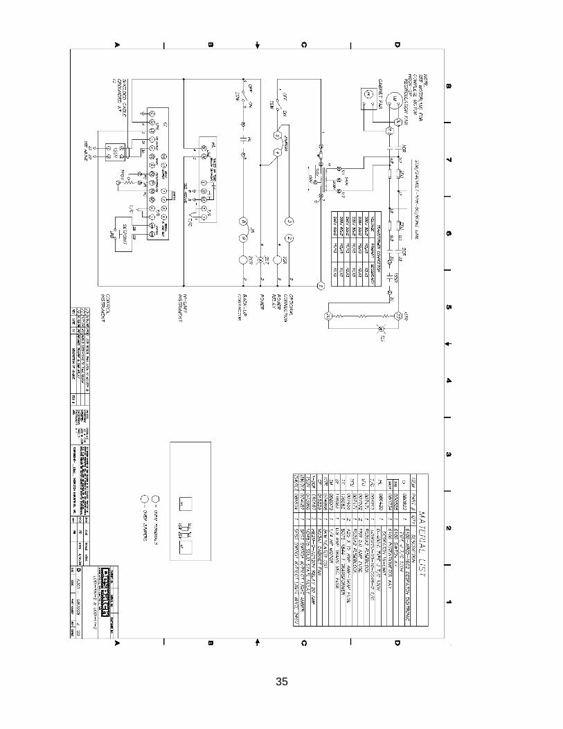
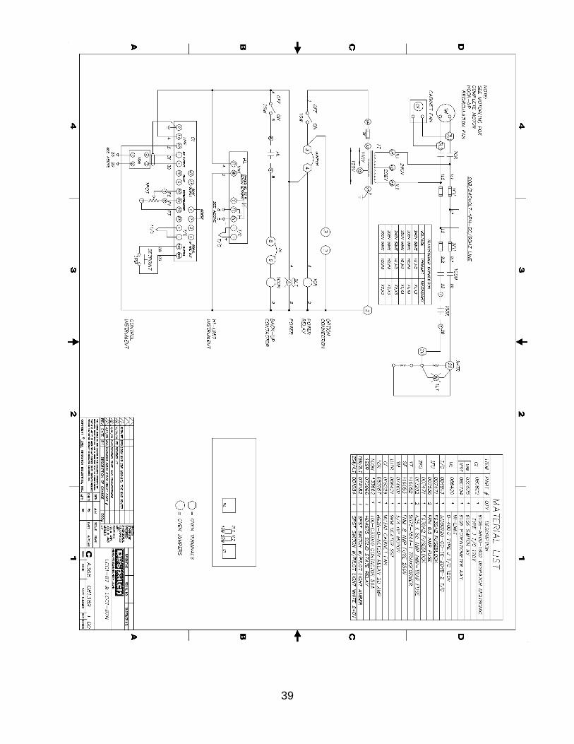
Drawings The drawings on the next pages are the electrical schematics for the following ovens:
LCC 1 - 11 - 2 & LCC 1 - 11N – 2
Digitronic Controller DA351-080928J00
MIC1462 Controller DA351-140028B00
LCC 1 - 54 - 2 & LCC 1 - 54N - 2 & LCC 1 - 54NV – 2
Digitronic Controller CA351-054552T00
MIC1462 Controller DA351-140029B00
LCC 1 - 87 - 2 & LCC 1 - 87N - 2 & LCC 1 - 87NV – 2
Digitronic Controller CA368-081389I00
MIC1462 Controller DA351-140030B00
35

36

37

38
39

40