
Layering and structural inheritance controls on fault zone ...
16
Layering and structural inheritance controls on fault zone structure in three dimensions: a case study from the northern Molasse Basin, Switzerland Vincent Roche 1,2* , Conrad Childs 1,2 , Herfried Madritsch 3 & Giovanni Camanni 1 1 Fault Analysis Group, UCD School of Earth Sciences, University College of Dublin, Belfield, Dublin 4, Ireland 2 Irish Centre for Research in Applied Geosciences, UCD School of Earth Sciences, University College Dublin, Belfield, Dublin 4, Ireland 3 Nagra, Hardstrasse 73, CH-5430 Wettingen, Switzerland VR, 0000-0002-9992-7433; CC, 0000-0001-8669-213X; GC, 0000-0001-9690-2583 Present address: GC, DiSTAR, Università degli Studi di Napoli ‘Federico II’, 80126 Naples, Italy * Correspondence: [email protected] Abstract: Mechanical heterogeneity of a sedimentary sequence exerts a primary control on the geometry of fault zones and the proportion of offset accommodated by folding. The Wildensbuch Fault Zone in the Swiss Molasse Basin, with a maximum throw of 40 m, intersects a Mesozoic section containing a thick (120 m) clay-dominated unit (Opalinus Clay) over- and underlain by more competent limestone units. Interpretation of a 3D seismic reflection survey indicates that the fault zone formed by upward propagation of an east–west-trending basement structure, through the Mesozoic section, in response to NE– SW Miocene extension. This configuration formed an array of left-stepping normal fault segments above and below the Opalinus Clay. In cross-section a broad monoclinal fold is observed in the Opalinus Clay. Folding, however, is not ubiquitous and occurs in the Opalinus Clay where fault segments above and below are oblique to one another; where they are parallel the fault passes through the Opalinus Clay with little folding. These observations demonstrate that, even in strongly heterogeneous sequences, here a four-fold difference in both Young’s modulus and cohesion between layers, the occurrence of folding may depend on the local relationship between fault geometry and applied stress field rather than rheological properties alone. Received 26 March 2019; revised 8 November 2019; accepted 13 November 2019 A key control on the geometry and nature of structures formed in response to extensional strains is the mechanical properties of the deformed rocks. This is most evident in sedimentary sequences where, for instance, the mode of fracture (Ferrill & Morris 2003), fracture or fault dip (Peacock & Sanderson 1992; Ferrill et al. 2017) and fault displacement gradients (Muraoka & Kamata 1983; Ferrill & Morris 2008; Roche et al. 2012) can change across bedding interfaces between lithologies of contrasting competence. Where the compe- tence contrast between interbedded lithologies is large, structures can step or become decoupled across the less competent units so that the sequence of rocks of varying mechanical properties, referred to as the mechanical stratigraphy (Corbett et al. 1987; Wilkins & Gross 2002; Laubach et al. 2009; Ferrill et al. 2017), has a significant impact on the propagation and evolution of extensional faults and fractures (e.g. Peacock & Zhang 1994; Childs et al. 1996; Vasquez et al. 2018). The impact of mechanical stratigraphy on extensional faulting is well documented for small faults at outcrop (Peacock & Sanderson 1992; Wilkins & Gross 2002; Ferrill & Morris 2003; Roche et al. 2012; Agosta et al. 2015) but until the advent of 3D seismic reflection data, studying this relationship in three dimensions was challenging (see Mansfield & Cartwright 1996; Kattenhorn & Pollard 2001). Over the past 10 years there have been many seismic- based studies of the impact of sequence on fault geometry and, in particular, on sequences that contain continuous thick salt units where extensional fault systems are entirely decoupled across the salt layer (Baudon & Cartwright 2008; Jackson & Rotevatn 2013; Tvedt et al. 2013; Wilson et al. 2013; Lăpădat et al. 2017; Deng & McClay 2019). Here we use a 3D seismic reflection survey to examine the impact of a thick (>120 m), clay-dominated, incompetent unit on normal fault geometry. Displacement across fault zones is accommodated by a combination of discontinuous and continuous deformation, which vary in relative importance over a fault (e.g. Grant & Kattenhorn 2004; Ferrill et al. 2011; Childs et al. 2017; Delogkos et al. 2017; Homberg et al. 2017). The continuous component is defined as a change in shape produced by structures that are below the scale of observations. This definition is scale dependent and continuous deformation includes, for example, deformation associated with faulting below the limit of seismic resolution. In contrast, discontinuous deformation is expressed as discrete discontinuities, such as fault offsets. Significant continuous deformation occurs at forced folds above upward propagating normal faults, particularly above less competent units within the faulted sequence (Ferrill et al. 2004; Jackson et al. 2006; Conneally et al. 2017; Lă pădat et al. 2017; Roche et al. 2017). Continuous deformation also occurs at relay zones between adjacent segments within a segmented fault array that serves to transfer displacement between adjacent segments leading, for example, to relay ramp development between normal faults that overlap one another along-strike (Peacock & Sanderson 1991; Childs et al. 1995; Camanni et al. 2019). In recent years, a number of seismic-based studies have analysed the variation in discontinuous and continuous deformation (Conneally et al. 2017; Lă pă dat et al. 2017) and demonstrated the complex spatial and temporal variation in the proportion of continuous deformation within fault zones. These and other studies demonstrate that, although the nature of the mechanical sequence is expected to exert a significant control on the distribution of ductile deformation, there are other geometrical controls that are less well understood. © 2020 The Author(s). This is an Open Access article distributed under the terms of the Creative Commons Attribution 4.0 License (http://creativecommons.org/ licenses/by/4.0/). Published by The Geological Society of London. Publishing disclaimer: www.geolsoc.org.uk/pub_ethics Research article Journal of the Geological Society Published online January 6, 2020 https://doi.org/10.1144/jgs2019-052 | Vol. 177 | 2020 | pp. 493–508 by guest on December 20, 2021 http://jgs.lyellcollection.org/ Downloaded from
Transcript of Layering and structural inheritance controls on fault zone ...

Layering and structural inheritance controls on fault zonestructure in three dimensions: a case study from the northernMolasse Basin, Switzerland
Vincent Roche1,2*, Conrad Childs1,2, Herfried Madritsch3 & Giovanni Camanni11 Fault Analysis Group, UCD School of Earth Sciences, University College of Dublin, Belfield, Dublin 4, Ireland2 Irish Centre for Research in Applied Geosciences, UCD School of Earth Sciences, University College Dublin, Belfield,Dublin 4, Ireland
3 Nagra, Hardstrasse 73, CH-5430 Wettingen, SwitzerlandVR, 0000-0002-9992-7433; CC, 0000-0001-8669-213X; GC, 0000-0001-9690-2583
Present address: GC, DiSTAR, Università degli Studi di Napoli ‘Federico II’, 80126 Naples, Italy*Correspondence: [email protected]
Abstract: Mechanical heterogeneity of a sedimentary sequence exerts a primary control on the geometry of fault zones and theproportion of offset accommodated by folding. The Wildensbuch Fault Zone in the Swiss Molasse Basin, with a maximumthrow of 40 m, intersects a Mesozoic section containing a thick (120 m) clay-dominated unit (Opalinus Clay) over- andunderlain by more competent limestone units. Interpretation of a 3D seismic reflection survey indicates that the fault zoneformed by upward propagation of an east–west-trending basement structure, through the Mesozoic section, in response to NE–SW Miocene extension. This configuration formed an array of left-stepping normal fault segments above and below theOpalinus Clay. In cross-section a broad monoclinal fold is observed in the Opalinus Clay. Folding, however, is not ubiquitousand occurs in the Opalinus Clay where fault segments above and below are oblique to one another; where they are parallel thefault passes through the Opalinus Clay with little folding. These observations demonstrate that, even in strongly heterogeneoussequences, here a four-fold difference in both Young’s modulus and cohesion between layers, the occurrence of folding maydepend on the local relationship between fault geometry and applied stress field rather than rheological properties alone.
Received 26 March 2019; revised 8 November 2019; accepted 13 November 2019
A key control on the geometry and nature of structures formed inresponse to extensional strains is the mechanical properties of thedeformed rocks. This is most evident in sedimentary sequenceswhere, for instance, the mode of fracture (Ferrill & Morris 2003),fracture or fault dip (Peacock & Sanderson 1992; Ferrill et al. 2017)and fault displacement gradients (Muraoka&Kamata 1983; Ferrill &Morris 2008; Roche et al. 2012) can change across bedding interfacesbetween lithologies of contrasting competence. Where the compe-tence contrast between interbedded lithologies is large, structures canstep or become decoupled across the less competent units so that thesequence of rocks of varyingmechanical properties, referred to as themechanical stratigraphy (Corbett et al. 1987; Wilkins & Gross 2002;Laubach et al. 2009; Ferrill et al. 2017), has a significant impact onthe propagation and evolution of extensional faults and fractures (e.g.Peacock & Zhang 1994; Childs et al. 1996; Vasquez et al. 2018).
The impact of mechanical stratigraphy on extensional faulting iswell documented for small faults at outcrop (Peacock & Sanderson1992; Wilkins & Gross 2002; Ferrill & Morris 2003; Roche et al.2012; Agosta et al. 2015) but until the advent of 3D seismicreflection data, studying this relationship in three dimensions waschallenging (see Mansfield & Cartwright 1996; Kattenhorn &Pollard 2001). Over the past 10 years there have been many seismic-based studies of the impact of sequence on fault geometry and, inparticular, on sequences that contain continuous thick salt unitswhere extensional fault systems are entirely decoupled across thesalt layer (Baudon & Cartwright 2008; Jackson & Rotevatn 2013;Tvedt et al. 2013; Wilson et al. 2013; Lapa dat et al. 2017; Deng &McClay 2019). Here we use a 3D seismic reflection survey toexamine the impact of a thick (>120 m), clay-dominated,incompetent unit on normal fault geometry.
Displacement across fault zones is accommodated by acombination of discontinuous and continuous deformation,which vary in relative importance over a fault (e.g. Grant &Kattenhorn 2004; Ferrill et al. 2011; Childs et al. 2017; Delogkoset al. 2017; Homberg et al. 2017). The continuous component isdefined as a change in shape produced by structures that are belowthe scale of observations. This definition is scale dependent andcontinuous deformation includes, for example, deformationassociated with faulting below the limit of seismic resolution. Incontrast, discontinuous deformation is expressed as discretediscontinuities, such as fault offsets. Significant continuousdeformation occurs at forced folds above upward propagatingnormal faults, particularly above less competent units within thefaulted sequence (Ferrill et al. 2004; Jackson et al. 2006;Conneally et al. 2017; Lapa dat et al. 2017; Roche et al. 2017).Continuous deformation also occurs at relay zones betweenadjacent segments within a segmented fault array that serves totransfer displacement between adjacent segments leading, forexample, to relay ramp development between normal faults thatoverlap one another along-strike (Peacock & Sanderson 1991;Childs et al. 1995; Camanni et al. 2019). In recent years, anumber of seismic-based studies have analysed the variation indiscontinuous and continuous deformation (Conneally et al. 2017;Lapa dat et al. 2017) and demonstrated the complex spatial andtemporal variation in the proportion of continuous deformationwithin fault zones. These and other studies demonstrate that,although the nature of the mechanical sequence is expected toexert a significant control on the distribution of ductiledeformation, there are other geometrical controls that are lesswell understood.
© 2020 The Author(s). This is an Open Access article distributed under the terms of the Creative Commons Attribution 4.0 License (http://creativecommons.org/licenses/by/4.0/). Published by The Geological Society of London. Publishing disclaimer: www.geolsoc.org.uk/pub_ethics
Research article Journal of the Geological Society
Published online January 6, 2020 https://doi.org/10.1144/jgs2019-052 | Vol. 177 | 2020 | pp. 493–508
by guest on December 20, 2021http://jgs.lyellcollection.org/Downloaded from
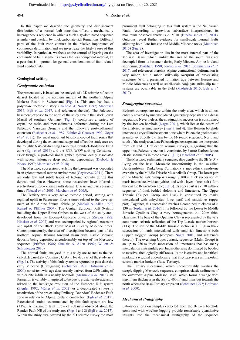
In this paper we describe the geometry and displacementdistribution of a normal fault zone that offsets a mechanicallyheterogeneous sequence in which a thick clay-dominated sequenceis under- and overlain by thick carbonate-rich formations. Differentparts of the fault zone contrast in the relative importance ofcontinuous deformation and we investigate the likely cause of thisvariability. In particular, we focus on the control of layering on thecontinuity of fault segments across the less competent interval, anaspect that is important for general considerations of fault-relatedfluid conductivity.
Geological setting
Geodynamic evolution
The present study is based on the analysis of a 3D seismic reflectiondataset located at the northern margin of the northern AlpineMolasse Basin in Switzerland (Fig. 1). This area has had apolyphase tectonic history (Diebold & Noack 1997; Madritsch2015; Egli et al. 2017, and references therein). The Paleozoicbasement, exposed to the north of the study area in the Black ForestMassif of southern Germany (Fig. 1), comprises a variety ofcrystalline rocks and metasediments deformed during the LatePaleozoic Variscan Orogeny and the following post-collisionalextension (Eisbacher et al. 1989; Echtler & Chauvet 1992; Geyeret al. 2011). The most important basement-rooted fault zones thatdeveloped during the extensional stage and affect the study area arethe roughly NW–SE-trending Freiburg–Bonndorf–Bodensee Faultzone (Egli et al. 2017) and the ENE–WSW-striking Constance–Frick trough, a post-collisional graben system locally associatedwith several kilometre deep sediment depocentres (Diebold &Noack 1997; Madritsch et al. 2018).
The Mesozoic succession overlying the basement was depositedin an epicontintental marine environment (Geyer et al. 2011). Thereare only few and subtle traces of tectonic activity during thisdepositional phase. However, some researchers have inferred areactivation of pre-existing faults during Triassic and Early Jurassictimes (Wetzel et al. 2003; Marchant et al. 2005).
The Tertiary was a very active tectonic period, starting withregional uplift in Paleocene–Eocene times related to the develop-ment of the Alpine flexural forebulge (Sinclair & Allen 1992;Kempf & Pfiffner 2004). The Central European Rift System,including the Upper Rhine Graben to the west of the study area,developed from the Eocene–Oligocene onwards (Ziegler 1992;Hinsken et al. 2007) and was accompanied by regional extensionand uplift of the Black Forest Massif in early Miocene times.Contemporaneously, the area of investigation became part of thenorthern Alpine flexural foreland basin with clastic Molassedeposits being deposited unconformably on top of the Mesozoicsequence (Pfiffner 1986; Sinclair & Allen 1992; Willett &Schlunegger 2010).
The normal faults analysed in this study are related to the so-called Hegau–Lake Constance Graben, located east of the study area(Fig. 1). The activity of this fault system is reported to post-date theearly Miocene (Burdigalian) (Schreiner 1992; Hofmann et al.2000), consistent with age data recently derived fromU/Pb dating ofvein calcite infills in a nearby borehole (Mazurek et al. 2018). Itsformation is variably interpreted to be due to crustal-scale extensionrelated to the late-stage evolution of the European Rift system(Ziegler 1992; Müller et al. 2002) or a deep-seated strike-slipreactivation of the pre-existing Freiburg–Bonndorf–Bodensee Faultzone in relation to Alpine foreland contraction (Egli et al. 2017).Extensional strains accommodated by this fault system are low(<1%). A maximum fault throw of 200 m is observed along theRanden Fault NE of the study area (Figs 1 and 2) (Egli et al. 2017).Within the study area covered by the 3D seismic survey the most
prominent fault belonging to this fault system is the NeuhausenFault. According to previous subsurface interpretations, itsmaximum observed throw is c. 50 m (Birkhäuser et al. 2001).Outcrops reveal further evidence for small-scale normal faultsaffecting both Late Jurassic and Middle Miocene rocks (Madritsch2015) (Fig. 2).
The area of investigation lies in the most external part of theMolasse Basin, which, unlike the area to the south, was notdecoupled from its basement during Early Miocene Alpine forelandshortening (Burkhard 1990; Jordan et al. 2015; Sommaruga et al.2017, and references therein). Alpine contractional deformation isvery minor, but a subtle strike-slip overprint of pre-existingstructures (with a presumed formation age between Eocene andMiddle Miocene) as well as small-scale conjugate strike-slip faultsystems are observable in the field (Madritsch 2015; Egli et al.2017).
Stratigraphic succession
Bedrock outcrops are rare within the study area, which is almostentirely covered by unconsolidated Quaternary deposits and a densevegetation. Nevertheless, the stratigraphic succession is constrainedby the Benken borehole (Nagra 2001), which lies at the centre ofthe analysed seismic survey (Figs 3 and 4). The Benken boreholeintersects a crystalline basement horst where Paleozoic gneisses andgranites are directly overlain by the Mesozoic sequence. North andsouth of the study area, Late Paleozoic graben segments are interpretedfrom 2D and 3D reflection seismic surveys, suggesting that theuppermost Paleozoic section is constituted by Permo-Carboniferousclastic sediments in these areas (Fig. 1) (Marchant et al. 2005).
TheMesozoic sedimentary sequence dips gently to the SE (c. 5°).Lying on the basal Mesozoic unconformity is the so-calledBundsandstein (Dinkelberg Formation) a metre-thick sandstoneoverlain by the Middle Triassic Muschelkalk Group. The lower partof the Muschelkalk Group is a roughly 100 m thick succession ofmarls intercalated with anhydrites and with a layer of rock salt (13 mthick in the Benken borehole; Fig. 3). Its upper part is a c. 70 m thicksequence of thick-bedded dolomite and limestone. The UpperTriassic (Keuper Group and Lias) is constituted by marls,intercalated with anhydrites (lower part) and sandstones (upperpart). Together, this succession reaches a combined thickness of c.130 m (Jordan et al. 2016). It is followed by the Lower to MiddleJurassic Opalinus Clay, a very homogeneous, c. 120 m thickclaystone. The base of the Opalinus Clay is represented by the verycontinuous seismic reflection of the Top-Liassic marker horizon(TLi). The rest of the Middle Jurassic section is a c. 80 m thicksuccession of marls intercalated with sand-rich limestone beds(Upper Dogger Group) (compare Nagra 2001, and referencestherein). The overlying Upper Jurassic sequence (Malm Group) isan up to 250 m thick succession of limestones that has marlyintercalation in its middle part but is otherwise dominated by beddedto massive, rheologically stiff rocks. Its top is erosive and karstified,marking a regional unconformity that also represents an importantseismic marker horizon (Base-Tertiary).
The Tertiary succession, which unconformably overlies thesteeply dipping Mesozoic sequence, comprises clastic sediments ofthe outermost Alpine Molasse Basin, which forms a wedge withmaximum thickness in the SE (c. 400 m) and thins out towards thenorth where the Base-Tertiary crops out (Schreiner 1992; Hofmannet al. 2000).
Mechanical stratigraphy
Laboratory tests on samples collected from the Benken boreholecombined with wireline logging provide remarkable quantitativeinsights into the mechanical stratigraphy of the sequence
494 V. Roche et al.
by guest on December 20, 2021http://jgs.lyellcollection.org/Downloaded from
(Nagra 2001; Giger & Marschall 2014). Rock properties for thedifferent formations encountered in the boreholewere calculated frommeasured P- and S-wave velocities and the density log, whichtogether can be used to assess depth variation in dynamic Young’smodulus, using the method presented by Roche & Van der Baan(2015) (Fig. 3). The calculations of Young’s modulus were calibratedto the results of a laboratory test programme performed on core plugssampled from the Benken borehole (Nagra 2001, and references
therein), which measured static Young’s modulus, cohesion andinternal friction. Although a detailed mechanical analysis based onthese properties is beyond the scope of this paper these data allowfor quantitative comparison between the mechanical properties ofthe units within the faulted sequence. This indicates that theunderlying and overlying Muschelkalk and Malm Groups aresignificantly stiffer and stronger than the Opalinus Clay, whichtherefore constitutes a less competent unit between more competent
Fig. 1. (a) Tectonic map of central northern Switzerland showing the location of the study area (modified after Nagra 2014). (b) and (c) show profiles 4.7and 4.2 respectively, modified after Jordan et al. (2015).
495Layering and structural controls on fault zone
by guest on December 20, 2021http://jgs.lyellcollection.org/Downloaded from

units. The Dogger Group and the Keuper Group are more mixedunits. A more detailed analysis of this mechanical stratigraphy andits effect on the faulting is presented in the discussion section.
Seismic data and interpretation
The 3D seismic dataset analysed in this study covers c. 50 km2 andwas acquired by the Swiss National Cooperative for RadioactiveWaste Disposal (Nagra) in 1997. The initial processing workflowand interpretation has been reported in detail by Birkhäuser et al.(2001). Prestack depth migration was carried out later to improveimage quality and reduce uncertainty in interpreted fault position.The 3D velocity model needed for this reprocessing was developediteratively on the basis of a pre-existing regional velocity model thatincluded five Mesozoic intervals (Meier et al. 2014), constrained byadditional well data and tomographic analysis. Initial results ofvelocity modelling were calibrated along the Benken borehole(Nagra 2001; see Fig. 4 for location). At the margins of the datacube, regional 2D seismic profiles that were previously depthmigrated (compare Meier et al. 2014, and references therein) wereconsidered as model control points. Compared with the originallegacy dataset the updated prestack depth migration cube has arevised polarity (SEG-inverse EU) and shows a generally increasedinterpretability (continuity of reflection, homogeneity of amplitudedistribution). The seismic interpretation referred to here andillustrated in Figure 4 was done on this reprocessed seismicdataset and may therefore vary slightly from previously publishedinterpretations based on the legacy dataset (Birkhäuser et al. 2001;Marchant et al. 2005).
Faults were mapped in three dimensions using a combination ofinline and crossline interpretation and horizon and seismic
attributes. The seismic horizon to well ties were based on syntheticseismograms derived for the Benken borehole (Meier et al. 2014)(Fig. 3). Our interpretation of the reprocessed data cube generallyagrees with the initial interpretation results of the legacy dataset byBirkhäuser et al. (2001), revealing the same overall structuralcharacteristics of the area. The Mesozoic sequence dips gentlytowards the SSE with a wedge of the Cenozoic Molasse depositsthickening continuously in the same direction. The most importantfault recognized in the study area is the Neuhausen Fault imaged inthe northeastern part of the seismic cube (Fig. 4). This normal faultis related to the Miocene evolution of the previously mentionedFreiburg–Bonndorf–Bodensee Fault zone (Egli et al. 2017).Another deformation zone, referred to as ‘Strukturzone vonNiderholz’ by Birkhäuser et al. (2001), is located in the SW ofthe survey area. It is constituted by a complex array of minor faultsascribed to a Triassic rifting event byMarchant et al. (2005) and wasnot interpreted in detail during this investigation. The interpretationof the Base-Mesozoic marker horizon reveals an east–westcrystalline horst structure in the central part of the survey area thatseparates Late Paleozoic graben elements of the Post-VariscanConstance–Frick trough system (compare Marchant et al. 2005;Madritsch et al. 2018). The southern and northern border faults ofthis feature, referred to as the Benken Horst, were apparentlyreactivated in post-Paleozoic times and are associated with twomore deformation zones in the overlying sedimentary sequence.The Rafz–Marthalen flexure occurs at the southern border of theBenken Horst and is characterized by a gentle east–west-trendingmonocline underlain by a number of similar-striking faults thatextend from the basement structure into the Mesozoic sequence(Figs 1 and 4). In the north, the Wildensbuch Fault Zone(‘Wildensbuch flexure’ of Birkhäuser et al. 2001 and Marchant
Fig. 2. Examples of normal faults cropping out in the area. (a) Panoramic view of the Randen Fault slip surface; corrugations and striations demonstratenormal movements (Egli et al. 2017). (b) Interpretation and rose diagram showing the strike of the fault. (c, d) Normal fault in the clastic sediments of theUpper Marine Molasse showing several metres of vertical offset. In the rose diagrams each circle represents 10% of data, the arrowhead represents theaverage value and the number of data are indicated (mesh elements orientation from photogrammetry in (b) and field measurements in (d)). Locations ofthese outcrops are indicated in Figure 1a.
496 V. Roche et al.
by guest on December 20, 2021http://jgs.lyellcollection.org/Downloaded from

Fig. 3. Stratigraphic sequence recorded in the Benken borehole (location shown in Fig. 4). From left to right: stratigraphy, lithostratigraphy, some of themain horizons identified in the seismic cube, P-wave velocities, density, impedance and RC series. Young’s modulus is calculated from the variation indensity and velocity. The Young’s modulus from laboratory tests is an average value derived from tests on samples collected in the borehole in differentintervals (Nagra 2001; Giger & Marschall 2014). Finally, a simplified fracture core log is indicated.
Fig. 4. (a) Simplified structural overview showing the main seismically imaged structures in the Muschelkalk. (b) A representative seismic section andinterpretation along the profile AA’ indicated in (a) with a vertical exaggeration of ×3.
497Layering and structural controls on fault zone
by guest on December 20, 2021http://jgs.lyellcollection.org/Downloaded from

et al. 2005) is characterized by a series of east–west-trending enechelon fault segments that occasionally extend from the basementup into the Molasse deposits. A more detailed structuralcharacterization of this complex fault zone was the main focus ofthis study and is presented in the following section.
The Wildensbuch Fault Zone
Field outcrops of the Wildensbuch Fault Zone are very scarce. Itsgeometry is entirely constrained by interpretation of 3D seismicdata. Accordingly, it has a complex 3D structure with strainpartitioned between discontinuous deformation accommodated by asystem of interacting fault segments and continuous deformation(i.e. folding). As will be demonstrated, partitioning of strain in threedimensions is strongly controlled by the sedimentary layering. Inthe following sections we first describe the 3D arrangement of thefault segments based on 3D seismic data with a series of maps(Fig. 5), seismic attributes (Fig. 6), a strike projection of the faultsurface (Fig. 7) and 3D views of faulted horizons (Fig. 8). We nextanalyse the orientation of the segments and the partitioning between
continuous and discontinuous deformations based on along-strikeand down-dip displacement profiles (Figs 9 and 10). In the finalsection, we broaden the analysis using data from the nearbyNeuhausen Fault.
3D segmentation
The geometry of the Wildensbuch Fault Zone varies through theMesozoic section. From the Base-Mesozoic to the Top-Lias theWildensbuch Fault Zone consists of two main segments referred toas segment A and segment B (Fig. 5c). These left-stepping segmentsinteract via a relay zone that is most readily mapped at the Base-Mesozoic level and can be seen in a map of seismic coherence at thislevel (Fig. 6a). Minor fault segments, labelled C and D in Figure 5,have been mapped between segments A and B, but these do nottransect the relay zone, which is therefore considered to be intact.The maximum throw on fault segments A and B at the Base-Mesozoic is 40 m (Fig. 9d). These two segments tip-out upwards onthe majority of the seismic lines within the Top-Muschelkalk (20%)or the Top-Lias (60%) (Fig. 7a); however, parts of segments A and
Fig. 5. Fault trace maps of the Wildensbuch Fault Zone in the Malm (IMm) (a), the Opalinus Clay (b) and the Base-Mesozoic formations (BMz) (c). In therose diagrams of fault strike each circle represents 10% of data and the arrow represents the average value. The strike data correspond to the strike measuredon areas of the fault surfaces above the Opalinus Clay (a), in the Opalinus Clay (b), and below the Opalinus Clay (c). SA–SD and S1–S5 refer to thedistinct fault segments as discussed in the text.
498 V. Roche et al.
by guest on December 20, 2021http://jgs.lyellcollection.org/Downloaded from

B are readily mapped across the Opalinus Clay and are continuousfrom the Base-Mesozoic up to the Malm. Locally, the upper tip ofsegment B bifurcates upwards to form a series of poorly resolvedsmall left-stepping relay zones (Bi. in Fig. 7a).
In the Jurassic section above the Opalinus Clay, the upper part ofthe Wildensbuch Fault Zone consists of a left-stepping en echelonarray of fault segments (Fig. 5a). The two largest segments within
the array, with maximum throws of 20–30 m, are located at theeastern and western extremities of the structure; these segmentsconnect downwards to segments A and B mapped in the lower partsof the Mesozoic section (Figs 5–7 and 9). Between those segments,several smaller faults with throws of 10 m or less are seen on seismicsections (Fig. 7, Section (2)) but unlike the larger faults are noteasily identifiable on seismic coherence maps (Fig. 6a). Unlike
Fig. 6. (a) Seismic variance attribute map and (b) horizon dip at the Malm (IMm), at the Top-Opalinus (TOp), at the Top-Lias (TLi), in the Muschelkalk(IMk) and at the Base-Mesozoic (BMz). SA, SB, S2, S3, S4 and S5 indicate the location of the fault segments labelled in Figure 5. NHF-E and NHF-Cindicate the eastern and the central segments of the Neuhausen Fault labelled in Figure 11. Variance attribute is a measure of the trace-to-trace similarity ofwaveforms and is commonly used to image discontinuities in seismic data such as at a fault (e.g. Saqab & Bourget 2015).
499Layering and structural controls on fault zone
by guest on December 20, 2021http://jgs.lyellcollection.org/Downloaded from

segments A and B these smaller faults cannot be traced across theOpalinus Clay but tip-out downwards within the Upper Dogger orthe Opalinus Clay formations. Most of the faults mapped in theUpper Mesozoic section offset the Base-Tertiary and extend into theTertiary Molasse, confirming that the faulting is of at least EarlyMiocene age, which is in line with the previously establishedregional tectonic history (Schreiner 1992; Madritsch 2015; Egliet al. 2017). The upper tips of the fault segments are difficult to
define because of the lack of reliable reflectors in this unit but smallfaults currently exposed at surface are associated with the studiedstructures (Fig. 2).
Finally, in the middle of the Mesozoic sedimentary sequence,constituted by the Lias and the Opalinus Clay intervals, we do notobserve significant faulting along the Wildensbuch Fault Zone. Theexceptions are segments A and B, which are present above andbelow the Opalinus Clay and are locally continuous through the
Fig. 7. (a) Strike projection of the Wildensbuch Fault Zone. The fault surfaces are represented in grey and fine black lines represent tip-lines. (b) Fourseismic sections and their interpretation at the locations indicated in (a). The colour coding and the terminology for the horizon are as in Figure 3. Thesegment names are as in Figure 5. Bi. indicates small fault bifurcations.
Fig. 8. A 3D view of two horizons centred on the Wildensbuch Fault Zone. The horizons have been rotated along a horizontal axis to remove the regionalSE tilt and highlight the local deformation. The fine lines correspond to depth contours of 10 m. The vertical exaggeration is ×3. The names of thesegments are as in Figures 5 and 11.
500 V. Roche et al.
by guest on December 20, 2021http://jgs.lyellcollection.org/Downloaded from
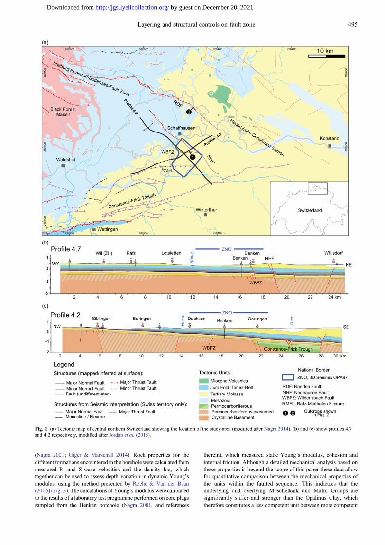
entire section (Figs 5 and 6 and sections (1) and (4) in Fig. 7b).Where discrete throws are mapped within the Opalinus Clay (e.g.section (1) in Fig. 7b) they are lower than the throw on both the over-and underlying Malm and the Muschelkalk intervals (Figs 9 and10). This locally low value in throw could potentially indicatelinkage between initially unconnected upper segments in the Malmand lower segments in Muschelkalk throughout the Opalinus Clay.However, there is no clear evidence to support this conclusion as nooverlapping areas are observed that would confirm the earlierexistence of down-dip relay zones. Therefore, there is a region in thecentre of the Wildensbuch Fault Zone at the level of the OpalinusClay where the mapped throws are reduced and locally absent,resulting in a hole within the 3D fault surface (Fig. 7), where faultoffset is accommodated by folding.
It is possible to locally map segments of the Wildensbuch FaultZone and their throws below the Base-Mesozoic into the Paleozoicbasement. Seismic interpretation at these levels is challenging and isnot presented here. As described above, and discussed in previoussections, previous work has identified the presence of a deep-seatednorthward dipping Paleozoic normal fault (Marchant et al. 2005),
which underlies the Wildensbuch Fault Zone and probably acted asthe locus for its formation.
Fault strike
Vertical variations in the structure of the Wildensbuch Fault Zoneare accompanied by changes in the strike of the component faultsegments. In the lower part of the fault, in the Muschelkalk interval,fault segments strike 105° on average (Fig. 5c). In the upper part ofthe fault, in the Malm interval, the en echelon fault segments strikeon average 125° (Fig. 5a), with significant variability in fault strikealong the segments with notably few portions striking more east–west; for instance, along segments B, 5 and 3 in Figure 5a. The twofault segments within the Opalinus Clay strike 110° on average,which is an intermediate value between the averages obtained forthe Muschelkalk and theMalm intervals. This rotation in fault strikewith depth, together with the en echelon trace map pattern aretypical of oblique reactivation of a pre-existing basement structure(Grant & Kattenhorn 2004; Giba et al. 2012; Worthington &Walsh2017). This hypothesis is discussed below.
Fig. 9. East–west along-strike displacement profiles in the Malm (a), the Top-Opalinus (b), the Top-Lias (c) and the Base-Mesozoic (d). Black, discretethrow; grey, total throw (i.e. discrete throw plus continuous deformation). The total throw profiles are calculated using a trim distance of 300 m on each sideof the fault (see text). The uncertainty in throw is c. 10 m. The colour coding and labels are as in Figures 3 and 5.
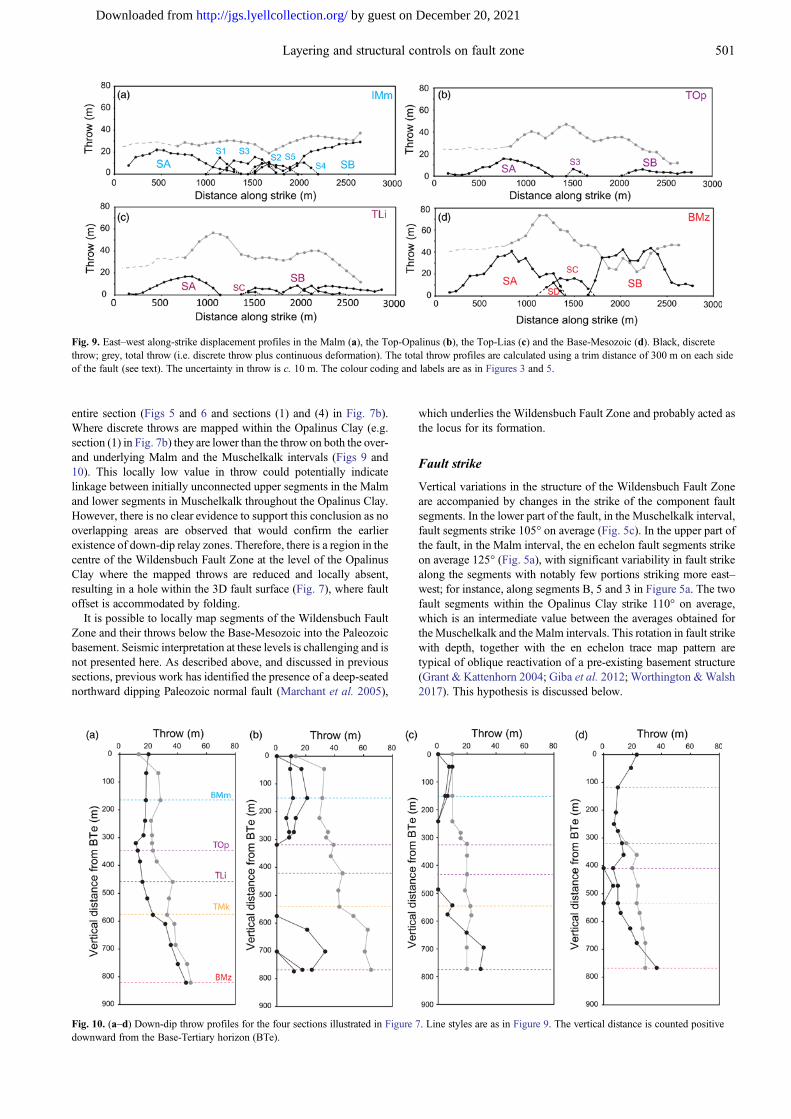
Fig. 10. (a–d) Down-dip throw profiles for the four sections illustrated in Figure 7. Line styles are as in Figure 9. The vertical distance is counted positivedownward from the Base-Tertiary horizon (BTe).
501Layering and structural controls on fault zone
by guest on December 20, 2021http://jgs.lyellcollection.org/Downloaded from

Continuous and discontinuous deformation
Continuous deformation occurs within relay zones allowing transferof displacement between fault segments. In bedded sequences thiscontinuous deformation is expressed as ramps of elevated bed dipbetween the relay bounding faults. Relay ramps are difficult toidentify where (1) layer dips in the relay ramp are low (i.e.displacement gradients on the bounding faults are low), and(2) where the spacing between the relay ramp-bounding faults isvery large or very small. Case (1) occurs for many segmentboundaries in theWildensbuch Fault Zone where throws are <40 m.However, the largest relay zones, for example, the one between faultsegments A and B within the Muschelkalk (Fig. 8), are readilymapped.
In addition to relay zones between fault segments, continuousdeformation within the Wildensbuch Fault Zone occurs as syntheticdip in the footwall and/or the hanging wall of the discrete faults (seeFerrill et al. 2005) and as open monoclines without any resolvablefaults (see Conneally et al. 2017). This deformation is clearly visiblein cross-section (Fig. 7b) and its distribution can be observed onhorizon dip maps (Fig. 6b). Monoclinal folding is most notablydeveloped within the Opalinus Clay, where a continuous monocli-nal limb is up to 300 m wide. In the upper and lower parts of thefault zone, in the Malm and Muschelkalk formations respectively,folding is more restricted and is focused between the fault segments.Continuous deformation progressively diminishes to the westtowards the tip of the Wildensbuch Fault Zone. However, a broadmonocline also occurs between segment A and the Neuhausen Faulttoward the west, indicating transfer of displacement between thesefaults (Fig. 8).
The total throw across theWildensbuch Fault Zone is measured asthe vertical difference between two along-strike profiles of horizonelevation drawn on the upthrown and downthrown sides of the zoneat the outer limits of deformation. Profiles of total throwmeasured inthis way along-strike and down-dip are shown in Figures 9 and 10,respectively. The magnitude of the continuous component of throwcan be estimated by the difference between the total throw and thediscrete throw represented by the profiles of fault throw. Althoughthere is a degree of subjectivity in measurement of absolute valuesfor the total offset across the Wildensbuch Fault Zone (for instance,owing to the Mesozoic succession’s regional dip), we consider thatthe estimated relative contributions of continuous and discontinuousdeformation are robust. Our estimates of total throw are locallyslightly lower than the discontinuous throw. This situation ariseswhere reflections are rotated slightly counter to the fault dipdirection either as a result of the very low regional dip or betweenadjacent faults. These minor errors are not corrected to avoidintroducing additional measurement subjectivity.
Displacement profiles along fault strike (Fig. 9) and selecteddown-dip profiles (Fig. 10) demonstrate that continuous deform-ation makes a relatively minor contribution to the total throw in theupper (Malm and Dogger units, Fig. 9a) and lower (i.e. the TriassicMuschelkalk unit, Fig. 9d) parts of the faulted section whereas thereis significant folding within the Opalinus Clay. The contribution ofcontinuous deformation varies over the fault surface; in theOpalinus Clay the contribution is generally over 60% but locally100% of the total throwwhereas above and below the contribution isgenerally c. 20%. The highest percentages are observed in thecentral part of the Wildensbuch Fault Zone.
The profiles of throw show that the Opalinus Clay is prone todeforming in a continuous manner with the development of openmonoclinal folding. Across theMalm and theMuschelkalk intervalsdeformation is predominantly by discrete faulting and continuousdeformation is largely associated with relay zones between faultsegments. It is apparent that lithology is the primary control on therelative importance of continuous deformation; however, there is
significant along-strike variability as demonstrated by comparisonbetween the seismic lines shown in Figure 7b and the associatedthrow profiles (Fig. 10). In section (1) in Figure 7b there is acontinuous fault cutting through the entire section, including theOpalinus Clay, whereas in section (2) in Figure 7b, 200 m to thewest, there are no discrete faults imaged and the throw isaccommodated entirely by folding. This lateral variability indicatesa second control on the occurrence of continuous deformation. Toinvestigate this secondary control we compare the throw distributionin the Wildensbuch Fault Zone with the nearby Neuhausen Fault.
The Neuhausen Fault
The Neuhausen Fault (Fig. 4) lies close to the northeastern limit ofthe seismic cube so that parts of the fault are not well imaged. Thoseparts of the fault that are well imaged (e.g. Fig. 11) provide a usefulcomparison with theWildensbuch Fault Zone as the two fault zonesshare the same geological setting and formed during Mioceneextension (Birkhäuser et al. 2001;Madritsch 2015; Egli et al. 2017).The Neuhausen Fault is composed of three main segments, referredto here as the Neuhausen Fault’s western, central and easternsegments (Fig. 11). The Neuhausen Fault’s western segment, closeto the edge of the data, is poorly imaged and is not further studiedhere. The central and eastern segments strike NW–SE and east–west, respectively. Regional mapping shows that the overall trend ofthe Neuhausen Fault is NW–SE and parallel to the larger RandenFault (Figs 1 and 2). Consequently, the Neuhausen Fault’s easternsegment represents a dog-leg in the main fault trace (Fig. 1). Despitetheir difference in strike, these two segments are clearly elements ofthe same fault and the continuity in their displacements along themapped length indicates that they formed at the same time. TheWildensbuch Fault Zone appears as an along-strike continuation ofthe eastern segment and follows the east–west trend parallel to theinferred basement structure (Marchant et al. 2005). TheWildensbuch Fault Zone can be mapped to the kink at the junctionbetween the Neuhausen Fault’s central and eastern segments, againindicating that it is kinematically related to the Neuhausen Fault.
Figure 11 shows examples of seismic sections and down-dipdisplacement profiles across the Neuhausen Fault. Within theseismic survey it has a generally higher throw than theWildensbuchFault Zone; that is, about 60 m on average and locally exceeding100 m. The upper end of this range is higher than previous estimatesbased on seismic interpretations in the time domain (Birkhäuseret al. 2001). The profiles show a slight downward decrease in throwacross the Neuhausen Fault’s eastern segment (Fig. 11c and d) and aslight downward increase in throw on its central segment (Fig. 11eand f). In all sections, the fault is continuous across the Mesozoicsection including the Opalinus Clay and the pronounced monoclinedevelopment seen in the Wildensbuch Fault Zone is absent on theNeuhausen Fault. There are, however, more subtle expressions ofthe impact of the Opalinus Clay on fault geometry and throwdistribution. For example, there is a slight decrease in thediscontinuous components of throw, observable in the displacementprofiles (see Fig. 11), and also a local change in fault dip at the baseof the Opalinus Clay (Top-Liassic), with higher dips in the lowerportion of the sequence than in the upper portion. This refractioncould be due to a change in friction angle, a change in failure mode,or linkage between earlier formed steep segments across a dip relayzone (for review, see Ferrill et al. 2017). Irrespective of origin,refracted fault traces reflect a sediment layering control on faultgeometry.
Fault geometric control on continuous deformation
TheWildensbuch Fault Zone displays significant variability in faultstrike above and below the Opalinus Clay. This is not a feature of the
502 V. Roche et al.
by guest on December 20, 2021http://jgs.lyellcollection.org/Downloaded from

Neuhausen Fault, on which, despite the difference in strike betweenthe Neuhausen Fault’s central and eastern segments, the fault tracesmapped on the Muschelkalk and Malm horizons have the samestrike. This difference between the two faults is represented in across-plot of fault strike above and below the Opalinus Claymeasured on selected representative sections (Fig. 12a). Themeasured difference in the strike of faults above and below theOpalinus Clay (angle β) for both theWildensbuch Fault Zone and theNeuhausen Fault is positively correlatedwith the proportion of throwaccommodated by continuous deformation within the Opalinus Clay(Fig. 12b). This illustrates that the larger the mismatch in throwacross the Opalinus Clay, the greater is the proportion of continuousdeformation. This relationship is defined primarily by datapointsderived from the Wildensbuch Fault Zone and is consistent with theobservation that the two areas where the Wildensbuch Fault Zoneforms a continuous fault surface across the Opalinus Clay withlimited folding are those where the strikes of faults in theMuschelkalk and the Malm intervals are parallel at c. 120°(compare Fig. 5a and c). These observations indicate that there is arelationship between fault geometry and the proportion ofcontinuous deformation within the Opalinus Clay and that, althoughthis relatively weaker lithology is more prone to continuous
deformation than other parts of the sequence, significant continuousdeformation occurs only in certain geometrical circumstances. Thedistribution of continuous deformation in sections above and belowthe Opalinus Clay is largely controlled by the locations of relayzones so that there is no relationship between β and the magnitude ofcontinuous deformation within these levels (Fig. 12c).
Discussion
Comparison between fault geometry and mechanicalstratigraphy
Rheological sequence has been identified as a primary control onthe occurrence of continuous deformation within fault zones on arange of scales from outcrop to seismic scale (e.g. Jackson et al.2006; Ferrill et al. 2017; Lapa dat et al. 2017; Deng & McClay2019); however, the actual mechanical properties of the sequenceare rarely reported (Morris et al. 2009; Roche et al. 2014; Ferrillet al. 2017), particularly at the large scale studied here. An extensiveprogramme of laboratory tests on samples collected from theBenken borehole in the centre of the study area (Nagra 2001; Giger& Marschall 2014) provides the data with which to constrain the
Fig. 11. (a, b) Maps of the Neuhausen Fault showing the main fault segments observed below and above the Opalinus Clay, respectively. (c–f ) Examples ofsections and down-dip throw profiles for the Neuhausen Fault showing no strong evidence of segmentation down fault dip. Line styles, colours coding andlabels are as in Figures 3, 5 and 9.
503Layering and structural controls on fault zone
by guest on December 20, 2021http://jgs.lyellcollection.org/Downloaded from

mechanical stratigraphy in the study area. The Young’s modulus ofthe Opalinus Clay is on average c. 10 GPa, in contrast to the muchstiffer rocks constituting the underlying and overlying Muschelkalkand Malm interval respectively with Young’s moduli of c. 40 GPa(Fig. 4). The Opalinus Clay has a low cohesion of 4 MPa and a lowfriction angle of 23° compared with the surrounding Malm andMuschelkalk with a cohesion greater than 20 MPa and a frictionangle higher than 40°. In the study area, a maximum temperature ofc. 85°C for the Opalinus Clay was reached during the Cretaceous fora depth of 1050 m, and a maximum burial depth of 1650 m wasreached during the Miocene for a temperature of c. 66°C (Mazureket al. 2006). Considering the evidence for late Miocene to recenterosion of c. 1000 m in the region of the northern Molasse Basin(Mazurek et al. 2006; von Hagke et al. 2012) the measured rockproperties probably do not equal those at the time of faulting (post-early Miocene) when the Molasse section overlying the faultedMesozoic units was thicker. Nevertheless, the relative strength andcompetence contrasts between the various units are unlikely to havebeen significantly different, particularly as the Jurassic Opalinus
Clay was already compacted at this time. The measured rockproperties for the Opalinus Clay are therefore consistent with theseismic observations of widespread continuous deformation in thisunit at the seismic scale.
Seismic mapping indicates that the sections above and below theOpalinus Clay are more likely to accommodate extension bydiscrete faulting than the Opalinus Clay. It is clear that themonoclinal folding in the Opalinus Clay is not a poorly resolvednormal fault, as the wavelength of the monocline is up to 300 m(Fig. 6b) and adjacent sections demonstrate that faults are readilyimaged across it elsewhere (e.g. Fig. 7b, section (1)). Borehole data,however, indicate that the Opalinus Clay is generally less prone todevelopment of brittle structures at the small scale. In theSchlattingen-1 borehole located about 5 km NE of our study area,and already within the adjacent Hegau–Lake Constance grabensystem, the Opalinus Clay is almost devoid of fractures whereasfault zones, shear fractures and veins are recorded above and below(Mazurek et al. 2018). The preferential location of fractures in theMalm and Muschelkalk competent units relative to the Opalinus
Fig. 12. (a) Plot of average fault strike at the Malm (IMm) v. average fault strike at the Base-Mesozoic (BMz) of selected locations along the WildensbuchFault Zone (WBFZ) and the Neuhausen Fault (NHF). (b, c) Plots of continuous deformation expressed as a percentage of the total throw v. β at the Top-Opalinus (TOp) and the Top-Lias (TLi) levels (b), and at the Malm (IMm) and Base-Mesozoic (BMz) levels (c). The β angle is the difference between thelocal strikes of the fault in the Malm and at the Base-Mesozoic levels. (d) Rose diagrams showing fault strike below (red) and above (blue) the OpalinusClay and the McCoss construction for the Wildensbuch Fault Zone (McCoss 1986). The orientations (1) and (2) correspond to the average orientations ofthe fault zone below and above the Opalinus Clay, respectively. The grey arrow indicates the direction of extension obtained from the McCoss constructionaccording to the two average orientations. The orientation (3) corresponds to the strike of a hypothetical normal fault formed without influence of pre-existing structures according to the direction of extension.
504 V. Roche et al.
by guest on December 20, 2021http://jgs.lyellcollection.org/Downloaded from

Clay incompetent unit is in accordance with differential stresses thatare higher in stiffer formations as suggested from numericalmodelling of the studied sequence (Hergert et al. 2015). However,the Schlattingen-1 borehole is located outside any monoclinalstructure, and therefore may not be representative of the fracturefrequency occurring in the Wildensbuch Fault Zone. Fracture datafrom the closer Benken borehole also show low fracture densities inthe Opalinus Clay, but a collection of sub-seismic-scale veins andshear fractures occurs within a narrow zone near 700 m depth (Fig. 3;Nagra 2001, and references therein). From an Opalinus Clay rocklaboratory at Mont Terri, located c. 100 km west of our study area in areverse fault regime, meso- and small-scale deformation of OpalinusClay is also reported to be dominantly brittle (Laurich et al. 2017;Jaeggi et al. 2018). Consequently, the possibility that the broadmonocline associated with the Wildensbuch Fault Zone is accom-modated by displacement on a numberof small faults that individuallyare below the limit of seismic resolution cannot be ruled out.
Structural inheritance and fault zone geometry
The Wildensbuch Fault Zone forms a left-stepping array ofsegments at the level of the Malm unit. The available outcrop data(Madritsch 2015; Egli et al. 2017) indicate that these are normal
fault segments and fault geometries and displacements areconsistent with normal offset. The en echelon arrangement of thesegments suggests that they formed under the influence of anunderlying basement structure. By comparing the overall trend ofthe fault zone (c. 090°) and the average strike of the segments withinthe zone (c. 125°), the McCoss construction (McCoss 1986;Worthington & Walsh 2017) can be used to derive the extensiondirection responsible for the formation of the segmented array; theresulting extension direction is c. 060° (Fig. 12d). This orientation isperpendicular to the trend of the Neuhausen Fault central segment(Fig. 11a) and the small-scale normal faults observed in the Tertiarysand (Fig. 2), and is consistent with previous field studies(Madritsch 2015; Egli et al. 2017) that report similar strikingnormal faults at surface invoking a NE–SW Miocene extensiondirection. We infer that the Neuhausen Fault and the WildensbuchFault Zone formed under the same Miocene extension and that theWildensbuch Fault Zone localized above a pre-existing east–westbasement structure. Although the seismic imaging within thebasement does not allow such deeper structures to be clearlyidentified, a Permo-Carboniferous normal fault with this trendbeneath the Wildensbuch Fault Zone is considered plausible from aregional geological perspective (Marchant et al. 2005; Madritschet al. 2018).
Fig. 13. Models of upward propagation of a pre-existing structure in a heterogeneous sequence. (a) The pre-existing structure is well oriented relative to thedirection of extension, resulting in a continuous vertical propagation through the layered sequence. (b) The pre-existing structure is oblique relative to thestress field, resulting in the formation of a monocline in the less competent unit and the formation of an en echelon structure with segments striking with adifferent orientation than the pre-existing structure. (c) The pre-existing structure is locally oblique. In (a)–(c) 1, 2 and 3 are successive steps showingvertical propagation. For illustration, we represent a different portion of the sedimentary sequence in the different steps. The grey arrows represent thedirection of extension at the time of reactivation. The grey layer corresponds to a less competent unit but continuous deformation extended above the layer.
505Layering and structural controls on fault zone
by guest on December 20, 2021http://jgs.lyellcollection.org/Downloaded from

Beneath the Opalinus Clay the individual fault segments strike c.20° anticlockwise of those above (Fig. 5); that is, intermediate inorientation between the general trend of the Wildensbuch FaultZone and the trend of the fault segments in the Malm unit. Thisstrike change is attributed to upward bifurcation and twisting of thefault from a continuous basement fault at depth. Upward twisting offault segments from a single reactivated basement structure has beendescribed from seismic data (Giba et al. 2012) and is well knownfrom analogue models of fault reactivation (Clifton et al. 2000;Corti 2008). In the case of the Wildensbuch Fault Zone this upwardtwisting is interrupted by the Opalinus Clay, across which there is astepwise change in the strike of fault segments presumed to be dueto mechanical decoupling across this weaker interval; similarstepwise changes in fault orientation are observed in reactivatedfault systems in the presence of highly ductile salt units (Jackson &Rotevatn 2013).
The Neushausen Fault cutting through the Mesozoic sectiondeveloped in response to Miocene extension. Egli et al. (2017)suggested that it also nucleated along a pre-existing basementstructure trending parallel to it and perpendicular to the inferredMiocene extension direction (i.e. NW–SE). Hence it was notreactivated in an oblique manner as was the Wildensbuch FaultZone. Asmentioned previously, the Neuhausen eastern segment hasan anomalous strike, forming a dog-leg in the otherwise continuousfault trace, and is aligned with the trace of the Wildensbuch FaultZone (Fig. 1). We interpret that at this location, the Neuhausen Faulthas locally followed the trace of the same roughly east–west-strikingbasement structure that lies beneath the Wildensbuch Fault Zone.This portion of the Neuhausen Fault does not seem to be segmentedin the sameway as theWildensbuch Fault Zone but its location at theedge of the seismic dataset does not allow for a similarly detailedinterpretation.
Model of formation of the fault zone under structuralinheritance and layering control
In this section we discuss aspects of the development of theWildensbuch Fault Zone that can be constrained by inspection of itsdisplacement distribution. Whereas the degree of partitioning of thedisplacement into continuous and discontinuous components variesover the fault, with a locally significant continuous componentwithin the Opalinus Clay, the distribution of the total displacementis largely unaffected by the Opalinus Clay and profiles of totaldisplacement vary systematically, both along-strike and down-dip(Figs 9 and 10). Therefore, the various components of the fault arrayare all parts of a single coherent structure. In this context,monoclines seen on seismic lines act to transfer displacementbetween fault segments above and below (e.g. Fig. 10c) and areeffectively dip relay zones between fault segments.
It could be considered that dip segmentation initially occurredalong the entire length of the Wildensbuch Fault Zone and that thefault segments above and below the Opalinus Clay later establishedlinkages at some locations to give the present-day 3D fault geometry(see Kattenhorn & Pollard 2001; Jackson& Rotevatn 2013; Lapa datet al. 2017; Deng & McClay 2019). However, we do not considerthis to be the case, partly because we do not see pronouncedmonocline development or overlapping fault segments, suggestiveof pre-existing relay zones, associated with those parts of theWildensbuch Fault Zone or the Neuhausen Fault that are continuousacross the Opalinus Clay. Also, the total throw associated withcontinuous fault traces is not significantly larger than that associatedwith fault traces that are segmented in cross-section and socontinuity is not established as throw increases, as would beexpected if a continuous fault was established by linkage of diprelay zones. Instead, we favour a model in which the degree ofsegmentation of the fault across the Opalinus Clay reflects
conditions during its initial propagation through the sequence andthe fault propagated across the Opalinus Clay more readily at somelocations than at others apparently depending on the faultorientation with respect to the direction of extension (Fig. 13).Faults that are continuous across the Opalinus Clay occur where thefault segments above and below the Opalinus Clay are parallel,suggesting that the fault was locally optimally oriented to propagatethrough the section. In contrast, in those areas where the fault isdiscontinuous across the Opalinus Clay, the segments above andbelow are oblique to one another, suggesting that the fault was notoptimally oriented at the time of fault propagation, fault propagationwas retarded by the Opalinus Clay, and a new and unconnected faultsegment formed above the Opalinus Clay. In the case of theWildensbuch Fault Zone, the orientations of these decouplednormal fault segments are compatible with the direction of Mioceneextension.
Conclusions
The Wildensbuch Fault Zone is formed by oblique reactivation of apre-existing basement structure that propagated upwards through apronounced mechanically layered stratigraphy. Throw is transferredbetween fault segments both laterally and vertically via relay zonesand open monoclines, so that a coherent displacement distribution ismaintained even for segments that are widely separated in map viewrelative to their displacement. The unit of key importance for faultzone development is the Opalinus Clay, a weak claystone that isover- and underlain by much more competent rock units. Whereasthe overlying and underlying units deformed in a brittle manner, theOpalinus Clay commonly deformed in a largely continuous mannerresulting in open monoclines. However, folding is by no meansubiquitous and despite its relatively low Young’s modulus andfailure angle, faults can be continuous across the Opalinus Clay onboth the Wildensbuch Fault Zone and the related Neuhausen Faultwith little or no continuous deformation. Folding is mostpronounced when fault segments above and below the OpalinusClay Formation have oblique strike to each other and is muchreduced to absent when the fault has the same strike above andbelow the Opalinus Clay. Therefore, the impact of an incompetentunit such as the Opalinus Clay on the geometry of fault zones is notsimply a function of the mechanical contrast at the time of faultingbut is also a function of the orientation of the fault zone to theextension direction. Increasing obliquity to the extension direction(e.g. owing to reactivation of precursor structure) favours faultsegmentation across such units, which show a tendency to deform ina continuous instead of discontinuous manner, whereas faultsstriking perpendicular to extension may show no segmentationdespite a strong mechanical contrast within sedimentary layering.
Acknowledgements Fault analyses were performed using TrapTester(Badley Earth Science) and Move software (Midland Valley). We thank themembers of the Fault Analysis Group and SilvioGige for many useful discussionson this topic, and D. Ferrill and C. Nussbaum for useful reviews of the paper.
Funding This research was supported by Nagra (Swiss National Cooperativefor the Disposal of Radioactive Waste) and by a consortium-sponsored projectbrokered by the Industry Technology Facilitator, and funded by Anadarko,ConocoPhillips (UK), Eni, ExxonMobil, Equinor, Shell, Total E&P UK andWoodside Energy. C. Childs is funded by Tullow Oil. This publication benefitedfrom research supported in part by a research grant from Science FoundationIreland (SFI) under Grant Number 13/RC/2092 and co-funded under theEuropean Regional Development Fund and by PIPCO RSG and its membercompanies.
Author contributions VR: Conceptualization (Lead), Formal analysis(Lead), Investigation (Lead), Methodology (Lead), Writing – Original Draft(Lead); CC: Conceptualization (Equal), Methodology (Equal), Supervision(Lead), Writing – Original Draft (Equal), Writing – Review & Editing (Equal);HM: Resources (Lead), Writing – Review & Editing (Equal); GC:
506 V. Roche et al.
by guest on December 20, 2021http://jgs.lyellcollection.org/Downloaded from

Conceptualization (Supporting), Formal analysis (Supporting), Investigation(Supporting), Methodology (Supporting)
Scientific editing by Karel Schulmann
ReferencesAgosta, F., Wilson, C. & Aydin, A. 2015. The role of mechanical stratigraphy on
normal fault growth across a Cretaceous carbonate multi-layer, central Texas(USA). Italian Journal of Geosciences, 134, 423–441, https://doi.org/10.3301/IJG.2014.20
Baudon, C. & Cartwright, J. 2008. Early stage evolution of growth faults: 3Dseismic insights from the Levant Basin, Eastern Mediterranean. Journal ofStructural Geology, 30, 888–898, https://doi.org/10.1016/j.jsg.2008.02.019
Birkhäuser, P., Roth, P., Meier, B. & Naef, H. 2001. 3D-Seismik: RäumlicheErkundung der mesozoischen Sedimentschichten im Zürcher Weinland. NagraTechnical Report, NTB 00-03. Nagra, Wettingen.
Burkhard, M. 1990. Aspects of the large-scale Miocene deformation in the mostexternal part of the Swiss Alps (sub-Alpine molasse to Jura fold belt). EclogaeGeologicae Helvetiae, 83, 559–583.
Camanni, G., Roche, V. et al. 2019. The three-dimensional geometry of relayzones within segmented normal faults. Journal of Structural Geology, 129,103895, https://doi.org/10.1016/j.jsg.2019.103895
Childs, C., Watterson, J. & Walsh, J.J. 1995. Fault overlap zones withindeveloping normal fault systems. Journal of the Geological Society, London,152, 535–549, https://doi.org/10.1144/gsjgs.152.3.0535
Childs, C., Nicol, A., Walsh, J.J. & Watterson, J. 1996. Growth of verticallysegmented normal faults. Journal of Structural Geology, 18, 1389–1397,https://doi.org/10.1016/S0191-8141(96)00060-0
Childs, C., Manzocchi, T., Nicol, A., Walsh, J.J., Soden, A.M., Conneally, J.C. &Delogkos, E. 2017. The relationship between normal drag, relay ramp aspectratio and fault zone structure. In: Childs, C., Holdsworth, R.E., Jackson, C.A.-L., Manzocchi, T., Walsh, J.J. & Yielding, G. (eds) The Geometry and Growthof Normal Faults. Geological Society, London, Special Publications, 439,355–372, https://doi.org/10.1144/SP439.16
Clifton, A.E., Schlische, R.W., Withjack, M.O. & Ackermann, R.V. 2000.Influence of rift obliquity on fault-population systematics: results ofexperimental clay models. Journal of Structural Geology, 22, 1491–1509,https://doi.org/10.1016/S0191-8141(00)00043-2
Conneally, J., Childs, C. & Nicol, A. 2017. Monocline formation during growthof segmented faults in the Taranaki Basin, offshore New Zealand.Tectonophysics, 721, 310–321, https://doi.org/10.1016/j.tecto.2017.06.036
Corbett, K., Friedman, M. & Spang, J. 1987. Fracture development andmechanical stratigraphy of Austin Chalk, Texas. AAPG Bulletin, 71, 17–28.
Corti, G. 2008. Control of rift obliquity on the evolution and segmentation of themain Ethiopian rift. Nature Geoscience, 1, 258–264, https://doi.org/10.1038/ngeo160
Delogkos, E., Manzocchi, T. et al. 2017. Throw partitioning across normal faultzones in the Ptolemais Basin, Greece. In: Childs, C., Holdsworth, R.E.,Jackson, C.A.-L., Manzocchi, T., Walsh, J.J. & Yielding, G. (eds) TheGeometry and Growth of Normal Faults. Geological Society, London, SpecialPublications, 439, 333–353, https://doi.org/10.1144/SP439.19
Deng, H. &McClay, K. 2019. Development of extensional fault and fold system:Insights from 3D seismic interpretation of the Enderby Terrace, NW Shelf ofAustralia. Marine and Petroleum Geology, 104, 11–28, https://doi.org/10.1016/j.marpetgeo.2019.03.003
Diebold, P. & Noack, T. 1997. Late Paleozoic troughs and Tertiary structures inthe eastern folded Jura. In: Pfiffner, O.A. et al. (eds) Deep Structure of theSwiss Alps–Results From NRP 20, Birkhäuser Boston, Cambridge, MA. 20,59–63.
Echtler, H.P. & Chauvet, A. 1992. Carboniferous convergence and subsequentcrustal extension in the southern Schwarzwald (SW Germany). GeodinamicaActa, 5, 37–49, https://doi.org/10.1080/09853111.1992.11105218
Egli, D., Mosar, J., Ibele, T. & Madritsch, H. 2017. The role of precursorystructures on Tertiary deformation in the Black Forest–Hegau region.International Journal of Earth Sciences, 106, 2297–2318, https://doi.org/10.1007/s00531-016-1427-8
Eisbacher, G.H., Lüschen, E. & Wickert, F. 1989. Crustal-scale thrusting andextension in the Hercynian Schwarzwald and Vosges, central Europe.Tectonics, 8, 1–21, https://doi.org/10.1029/TC008i001p00001
Ferrill, D.A. & Morris, A.P. 2003. Dilational normal faults. Journal of StructuralGeology, 25, 183–196, https://doi.org/10.1016/S0191-8141(02)00029-9
Ferrill, D.A. & Morris, A.P. 2008. Fault zone deformation controlled bycarbonate mechanical stratigraphy, Balcones fault system, Texas. AAPGBulletin, 92, 359–380, https://doi.org/10.1306/10290707066
Ferrill, D.A., Sims, D.W., Waiting, D.J., Morris, A.P., Franklin, N.M. & Schultz,A.L. 2004. Structural framework of the Edwards Aquifer recharge zone insouth–central Texas. Geological Society of America Bulletin, 116, 407–418,https://doi.org/10.1130/B25174.1
Ferrill, D.A., Morris, A.P., Sims, D.W., Waiting, D.J. & Hasegawa, S. 2005.Development of synthetic layer dip adjacent to normal faults. In: Sorkhabi, R.& Tsuji, Y. (eds) Faults, Fluid Flow, and Petroleum Traps. AAPG Memoirs,85, 125–138.
Ferrill, D.A., Morris, A.P., McGinnis, R.N., Smart, K.J. & Ward, W.C. 2011.Fault zone deformation and displacement partitioning in mechanically layered
carbonates: The Hidden Valley fault, central Texas. AAPG Bulletin, 95,1383–1397, https://doi.org/10.1306/12031010065
Ferrill, D.A., Morris, A.P., McGinnis, R.N., Smart, K.J., Wigginton, S.S. & Hill,N.J. 2017. Mechanical stratigraphy and normal faulting. Journal of StructuralGeology, 94, 275–302, https://doi.org/10.1016/j.jsg.2016.11.010
Geyer, O.F., Gwinner, M.P., Geyer, M., Nitsch, E. & Simon, T. 2011. Geologievon Baden-Württemberg. Schweizerbart, Stuttgart.
Giba, M., Walsh, J.J. & Nicol, A. 2012. Segmentation and growth of an obliquelyreactivated normal fault. Journal of Structural Geology, 39, 253–267, https://doi.org/10.1016/j.jsg.2012.01.004
Giger, S. & Marschall, P. 2014. Geomechanical properties, rock models andin-situ stress conditions for Opalinus Clay in Northern Switzerland. NagraWorking Report, NAB 14-01. Nagra, Wettingen.
Grant, J.V. &Kattenhorn, S.A. 2004. Evolution of vertical faults at an extensionalplate boundary, southwest Iceland. Journal of Structural Geology, 26,537–557, https://doi.org/10.1016/j.jsg.2003.07.003
Hergert, T., Heidbach, O., Reiter, K., Giger, S.B. & Marschall, P. 2015. Stressfield sensitivity analysis in a sedimentary sequence of the Alpine foreland,northern Switzerland. Solid Earth, 6, 533–552, https://doi.org/10.5194/se-6-533-2015
Hinsken, S., Ustaszewski, K. & Wetzel, A. 2007. Graben width controlling syn-rift sedimentation: the Palaeogene southern Upper Rhine Graben as anexample. International Journal of Earth Sciences, 96, 979–1002, https://doi.org/10.1007/s00531-006-0162-y
Hofmann, F., Schlatter, R. & Weh, M. 2000. Erläuterungen zum Blatt 1011Beggingen (Südhälfte) mit SW-Anteil von Blatt 1012 Singen. GeologischerAtlas der Schweiz, 1:25.000.
Homberg, C., Schnyder, J., Roche, V., Leonardi, V. & Benzaggagh, M. 2017. Thebrittle and ductile components of displacement along fault zones. In: Childs, C.,Holdsworth, R.E., Jackson, C.A.-L., Manzocchi, T., Walsh, J.J. & Yielding, G.(eds) TheGeometry andGrowth of Normal Faults. Geological Society, London,Special Publications, 439, 395–412, https://doi.org/10.1144/SP439.21
Jackson, C.A.L. & Rotevatn, A. 2013. 3D seismic analysis of the structure andevolution of a salt-influenced normal fault zone: a test of competing faultgrowth models. Journal of Structural Geology, 54, 215–234, https://doi.org/10.1016/j.jsg.2013.06.012
Jackson, C.A.L., Gawthorpe, R.L. & Sharp, I.R. 2006. Style and sequence ofdeformation during extensional fault-propagation folding: examples from theHammam Faraun and El-Qaa fault blocks, Suez Rift, Egypt. Journal ofStructural Geology, 28, 519–535, https://doi.org/10.1016/j.jsg.2005.11.009
Jaeggi, D., Laurich, B., Nussbaum, C., Schuster, K. & Connolly, P. 2018.Tectonic structure of the ‘Main Fault’ in the Opalinus Clay, Mont Terri rocklaboratory (Switzerland). In: Bossart, P. & Milnes, A. (eds) Mont Terri RockLaboratory, 20 Years. Swiss Journal of Geosciences, Supplement, vol 5.Birkhäuser, Cham, 68–86.
Jordan, P., Malz, A., Heuberger, S., Pietsch, J., Kley, J. & Madritsch, H. 2015.Regionale geologische Profilschnitte durch die Nordschweiz und 2D-Bilanzierung der Fernschubdeformation im östlichen Faltenjura: Arbeitsberichtzu SGT Etappe 2. Nagra Arbeitsbericht, NAB 14. Nagra, Wettingen.
Jordan, P., Pietsch, J.S. et al. 2016. The middle to late Triassic Bänkerjoch andKlettgau formations of northern Switzerland. Swiss Journal of Geosciences,109, 257–284, https://doi.org/10.1007/s00015-016-0218-3
Kattenhorn, S.A. & Pollard, D.D. 2001. Integrating 3-D seismic data, fieldanalogs, and mechanical models in the analysis of segmented normal faultsin the Wytch Farm oil field, southern England, United Kingdom. AAPGBulletin, 85, 1183–1210, https://doi.org/10.1306/8626CA91-173B-11D7-8645000102C1865D
Kempf, O. & Pfiffner, O.A. 2004. Early Tertiary evolution of the North AlpineForeland Basin of the Swiss Alps and adjoining areas. Basin Research, 16,549–567, https://doi.org/10.1111/j.1365-2117.2004.00246.x
La pa dat, A., Imber, J., Yielding, G., Iacopini, D., McCaffrey, K.J., Long, J.J. &Jones, R.R. 2017. Occurrence and development of folding related to normalfaulting within a mechanically heterogeneous sedimentary sequence: a casestudy from Inner Moray Firth, UK. In: Childs, C., Holdsworth, R.E., Jackson,C.A.-L., Manzocchi, T., Walsh, J.J. & Yielding, G. (eds) The Geometry andGrowth of Normal Faults. Geological Society, London, Special Publications,439, 373–394, https://doi.org/10.1144/SP439.18
Laubach, S.E., Olson, J.E.&Gross,M.R. 2009.Mechanical and fracture stratigraphy.AAPG Bulletin, 93, 1413–1426, https://doi.org/10.1306/07270909094
Laurich, B., Urai, J.L. & Nussbaum, C. 2017. Microstructures and deformationmechanisms in Opalinus Clay: Insights from scaly clay from the Main Fault inthe Mont Terri Rock Laboratory (CH). Solid Earth, 8, 27–44, https://doi.org/10.5194/se-8-27-2017
Madritsch, H. 2015. Outcrop-scale fracture systems in the Alpine foreland ofcentral northern Switzerland: kinematics and tectonic context. Swiss Journal ofGeosciences, 108, 155–181, https://doi.org/10.1007/s00015-015-0203-2
Madritsch, H., Naef, H., Meier, B., Franzke, H.J. & Schreurs, G. 2018.Architecture and kinematics of the Constance–Frick Trough (NorthernSwitzerland): implications for the formation of post-Variscan basins in theforeland of the Alps and scenarios of their Neogene reactivation. Tectonics,37, 2197–2220, https://doi.org/10.1029/2017TC004945
Mansfield, C.S. & Cartwright, J.A. 1996. High resolution fault displacementmapping from three-dimensional seismic data: evidence for dip linkage duringfault growth. Journal of Structural Geology, 18, 249–263, https://doi.org/10.1016/S0191-8141(96)80048-4
507Layering and structural controls on fault zone
by guest on December 20, 2021http://jgs.lyellcollection.org/Downloaded from

Marchant, R., Ringgenberg, Y., Stampfli, G., Birkhäuser, P., Roth, P. &Meier, B.2005. Paleotectonic evolution of the Zürcher Weinland (northernSwitzerland), based on 2D and 3D seismic data. Eclogae GeologicaeHelvetiae, 98, 345–362, https://doi.org/10.1007/s00015-005-1171-8
Mazurek, M., Hurford, A.J. & Leu, W. 2006. Unravelling the multi-stage burialhistory of the SwissMolasse Basin: integration of apatite fission track, vitrinitereflectance and biomarker isomerisation analysis. Basin Research, 18, 27–50,https://doi.org/10.1111/j.1365-2117.2006.00286.x
Mazurek, M., Davis, D.W., Madritsch, H., Rufer, D., Villa, I.M., Sutcliffe, C.N.& Traber, D. 2018. Veins in clay-rich aquitards as records of deformation andfluid-flow events in northern Switzerland. Applied Geochemistry, 95, 57–70,https://doi.org/10.1016/j.apgeochem.2018.05.010
McCoss, A.M. 1986. Simple constructions for deformation in transpression/transtension zones. Journal of Structural Geology, 8, 715–718, https://doi.org/10.1016/0191-8141(86)90077-5
Meier, B., Kuhn, P., Roth, P. & Madritsch, H. 2014. Tiefenkonvertierung derregionalen Strukturinterpretation der Nagra 2D-Seismik 2011/12. NagraWorking Report, NAB 14-34. Nagra, Wettingen.
Morris, A.P., Ferrill, D.A. & McGinnis, R.N. 2009. Mechanical stratigraphy andfaulting in Cretaceous carbonates. AAPG Bulletin, 93, 1459–1470, https://doi.org/10.1306/04080909011
Müller, W.H., Naef, H. & Graf, H.R. 2002. Geologische Entwicklung derNordschweiz, Neotektonik und Langzeitszenarien Zürcher Weinland. Nagra,Wettingen.
Muraoka, H. & Kamata, H. 1983. Displacement distribution along minor faulttraces. Journal of Structural Geology, 5, 483–495, https://doi.org/10.1016/0191-8141(83)90054-8
Nagra 2001. Sondierbohrung Benken – Untersuchungsbericht. NagraTechnischer Bericht, NTB 00-01. Nagra, Wettingen.
Nagra 2014. SGT Etappe 2: Vorschlag weiter zu untersuchender geologischerStandortgebiete mit zugehörigen Standortarealen für die Oberflächenanlage:Geologische Grundlagen / Dossier II. Nagra Technical Report NTB 14-02.Wettingen, Nagra.
Peacock, D.C.P. & Sanderson, D.J. 1991. Displacements, segment linkage andrelay ramps in normal fault zones. Journal of Structural Geology, 13,721–733, https://doi.org/10.1016/0191-8141(91)90033-F
Peacock, D.C.P. & Sanderson, D.J. 1992. Effects of layering and anisotropy onfault geometry. Journal of the Geological Society, London, 149, 793–802,https://doi.org/10.1144/gsjgs.149.5.0793
Peacock, D.C.P. & Zhang, X. 1994. Field examples and numerical modelling ofoversteps and bends along normal faults in cross-section. Tectonophysics, 234,147–167, https://doi.org/10.1016/0040-1951(94)90209-7
Pfiffner, O.A. 1986. Evolution of the north Alpine foreland basin in the CentralAlps. In: Allen, P.A. & Homewood, P. (eds) Foreland Basins. InternationalAssociation of Sedimentologists, Special Publications, 8, 219–228.
Roche, V. & Van der Baan, M. 2015. The role of lithological layering and porepressure on fluid-induced microseismicity. Journal of Geophysical Research:Solid Earth, 120, 923–943, https://doi.org/10.1002/2014JB011606
Roche, V., Homberg, C. & Rocher, M. 2012. Fault displacement profiles inmultilayer systems: from fault restriction to fault propagation. Terra Nova, 24,499–504, https://doi.org/10.1111/j.1365-3121.2012.01088.x
Roche, V., Homberg, C., David, C. & Rocher, M. 2014. Normal faults, layeringand elastic properties of rocks. Tectonophysics, 622, 96–109, https://doi.org/10.1016/j.tecto.2014.03.006
Roche, V., Homberg, C., van der Baan, M. & Rocher, M. 2017. Widening ofnormal fault zones due to the inhibition of vertical propagation. In: Childs,C., Holdsworth, R.E., Jackson, C.A.-L., Manzocchi, T., Walsh, J.J. &Yielding, G. (eds) The Geometry and Growth of Normal Faults. GeologicalSociety, London, Special Publications, 439, 271–288, https://doi.org/10.1144/SP439.5
Saqab, M.M. & Bourget, J. 2015. Structural style in a young flexure-inducedoblique extensional system, north-western Bonaparte Basin, Australia.Journal of Structural Geology, 77, 239–259, https://doi.org/10.1016/j.jsg.2015.06.002
Schreiner, A. 1992. Hegau und westlicher Bodensee. Geologische. Karte vonBaden-Württemberg 1:50 000, Erläuterungen.
Sinclair, H.D. & Allen, P.A. 1992. Vertical versus horizontal motions in theAlpine orogenic wedge: stratigraphic response in the foreland basin. BasinResearch, 4, 215–232, https://doi.org/10.1111/j.1365-2117.1992.tb00046.x
Sommaruga, A., Mosar, J., Schori, M. & Gruber, M. 2017. The role of theTriassic evaporites underneath the North Alpine Foreland. In: Soto, J.I.,Flinch, J.F. & Tari, G. (eds) Permo-Triassic Salt Provinces of Europe, NorthAfrica and the Atlantic Margins, Elsevier, Amsterdam, 447–466.
Tvedt, A.B., Rotevatn, A., Jackson, C.A.L., Fossen, H. & Gawthorpe, R.L. 2013.Growth of normal faults in multilayer sequences: a 3D seismic case study fromthe Egersund Basin, Norwegian North Sea. Journal of Structural Geology, 55,1–20, https://doi.org/10.1016/j.jsg.2013.08.002
Vasquez, L., Nalpas, T., Ballard, J.F., Veslud, C.L.C.D., Simon, B., Dauteuil, O.& Bernard, X.D. 2018. 3D geometries of normal faults in a brittle–ductilesedimentary cover: Analogue modelling. Journal of Structural Geology, 112,29–38, https://doi.org/10.1016/j.jsg.2018.04.009
von Hagke, C., Cederbom, C.E., Oncken, O., Stöckli, D.F., Rahn, M.K. &Schlunegger, F. 2012. Linking the northern Alps with their foreland: the latestexhumation history resolved by low temperature thermochronology.Tectonics, 31, TC5010, https://doi.org/10.1029/2011TC003078
Wetzel, A., Allenbach, R. & Allia, V. 2003. Reactivated basement structuresaffecting the sedimentary facies in a tectonically “quiescent” epicontinentalbasin: an example from NW Switzerland. Sedimentary Geology, 157,153–172, https://doi.org/10.1016/S0037-0738(02)00230-0
Wilkins, S.J. & Gross, M.R. 2002. Normal fault growth in layered rocks at SplitMountain, Utah: influence of mechanical stratigraphy on dip linkage, faultrestriction and fault scaling. Journal of Structural Geology, 24, 1413–1429,https://doi.org/10.1016/S0191-8141(01)00154-7
Willett, S.D. & Schlunegger, F. 2010. The last phase of deposition in the SwissMolasse Basin: from foredeep to negative‐alpha basin. Basin Research, 22,623–639, https://doi.org/10.1111/j.1365-2117.2009.00435.x
Wilson, P., Elliott, G.M., Gawthorpe, R.L., Jackson, C.A.L., Michelsen, L. &Sharp, I.R. 2013. Geometry and segmentation of an evaporite-detachednormal fault array: 3D seismic analysis of the southern Bremstein FaultComplex, offshore mid-Norway. Journal of Structural Geology, 51, 74–91,https://doi.org/10.1016/j.jsg.2013.03.005
Worthington, R.P. & Walsh, J.J. 2017. Timing, growth and structure of areactivated basin-bounding fault. In: Childs, C., Holdsworth, R.E., Jackson,C.A.-L., Manzocchi, T., Walsh, J.J. & Yielding, G. (eds) The Geometry andGrowth of Normal Faults. Geological Society, London, Special Publications,439, 511–531, https://doi.org/10.1144/SP439.14
Ziegler, P.A. 1992. European Cenozoic rift system. Tectonophysics, 208, 91–111,https://doi.org/10.1016/0040-1951(92)90338-7
508 V. Roche et al.
by guest on December 20, 2021http://jgs.lyellcollection.org/Downloaded from