Laura Williams Journal PART C Final
30
description
Â
Transcript of Laura Williams Journal PART C Final


PART C

0\�UVW�LWHUDWLRQ�ZDV�QRW�LQIRUPHG�E\�DQ\�SDUWLFXODUO\�LQVLJKWIXO�PHWKRGRORJ\��,�ZDV�YDJXHO\�WU\LQJ�WR�QG�D�9RURQRL�
seed that produced a lot of large faces oriented upstream.
It is obviously not particularly effective as indicated by the
lack of particles inside and vice versa. Lots of particles
were bouncing off the closed cell at the periphery, which
was a wasted opportunity. The upper exit point is also at
the end of an effectively straight line between 4 cells. This
is not establishing a barrier to the particles’ release.
ITERATION 1.
58 PROJECT PROPOSAL
LITTER FLOW & CELL CONFIGURATION
In my Part B crit it was suggested that I use computational fluid dynamics to explore the configurations of cells in the proposed filtration system. This was a very constructive suggestion as it helped me to approach the development process in a more systematic and evidence-based manner. I used Maya, an Autodesk animation, modelling and simulation software package, to test various cell configurations for their ability to retain particles.
In Maya it is possible to set up particle emitters, attractors and colliders in a way that you can see how particles interact with a static obstacles when acted on by a force. To test my iterations I set up a section of the creek with the design intervention midway along the length. Particle emitters were installed upstream and Newton forces were placed downstream (one near the exit points of the system to imitate the lateral suction, another further along to represent the pull downstream). The system was designated as a passive particle collider, meaning that particles would have to interact with it as a solid object. I opted to go with this method because I felt that the particle (litter) behaviour was my key concern.
I ran a simulation in Maya after creating each iteration and incorporated the lessons from that version into the subsequent proposal. I documented this process in the following pages. The images on top are from my Maya trials; the images below are from Rhino and have been included for clarity. The colourful dots are the particles released into the simulation. The aim was to achieve the maximum number of particles inside the system and a minimum outside. All simulations were run under the same conditions.
I acknowledge that there is a flaw in the logic of this method. In theory, the most effective system would be the one that blocked off the entire stream, as it would allow zero particles to pass through. However, damming the stream is not the objective and would be prohibitive to the movement of any aquatic fauna. I chose to stop projecting the intervention out into the stream when I felt that the vast majority of particles were being retained by system. The particles typically gathered around the forces (designated by the little black asterisk shapes) in the screen shots, so the amount of particles you see in the screen shots is more or less the total amount of particles operating in the simulation. Therefore, when there are no particles accruing near the forces this is because they are being successfully retained by the simulation. As such, there is a point when it is no more effective to project further outwards and therefore it is unnecessary to block off the stream.
C.1 DESIGN CONCEPT

Opening that outer cell and relocating an exit point
did improve retention, but there were still a lot of
particles bypassing the whole system. This iteration
did not project far enough out into the Creek.
ITERATION 2.
An intervention that projected further into the creek did extract
more particles, but it’s obvious that there are a lot of inactive
FHOOV�LQ�WKLV�LWHUDWLRQ��7KLV�PDWHULDO�LQHIFLHQF\�VHHPHG�OLNH�D�betrayal of the attempted environmental conscientiousness
of the project and should be avoided where possible.
ITERATION 3.
PROJECT PROPOSAL 59

Here I tried to mimic the reach of the previous iteration but with
larger, fewer cells to minimise material wastage. As indicated
by the cluster at the bottom left of the image, this was not
entirely successful. There was a relatively direct route between
3 cells that meant particles were spilling out an exit point.
ITERATION 4.In this iteration I tried to install further obstacles (by
creating a Voronoi diagram within a Voronoi cell selecting
sub-cells) to direct the flow of the particles into the
OWUDWLRQ�V\VWHP�DQG�PLWLJDWH�WKH�VXFWLRQ�RXW�RI�WKH�system. This was only partially effective because particles
were spilling both towards and away from the design. I
evidently chose the wrong geometry for the obstacles.
ITERATION 5.
60 PROJECT PROPOSAL

I changed both the obstacles and the seed of the Voronoi used
IRU�WKH�OWUDWLRQ�V\VWHP��,�ZDV�ORRNLQJ�IRU�D�VHHG�ZHUH�WKH�FHOOV�at the periphery downstream projected out further than the
cells upstream. I thought I could use this as an opportunity for
an additional entry, but didn’t create the apertures optimally.
Also, there were too many openings aligned again.
ITERATION 6.
In this iteration I inserted a couple more obstacles to
control the flow inside and outside the intervention. One
obstacle channels the flow of particles more precisely into
the system and the other blocks one of the exit points.
ITERATION 7.
PROJECT PROPOSAL 61

7KLV�QDO�LWHUDWLRQ�VLPSO\�LQFOXGHG�D�FRXSOH�PRUH�LQWHUQDO�obstacles to stop the direct flow of litter out of the system.
ITERATION 8.
62 PROJECT PROPOSAL
FINAL CONFIGURATION

PROJECT PROPOSAL 63
I attempted to verify my results from the Maya simulation XVLQJ� D� JHQXLQH� FRPSXWDWLRQDO� XLG� G\QDPLFV� SURJUDP��RealFlow was recommended because it enables users to combine solvers so that you can, for example, accurately WHVW�WKH�EHKDYLRXU�RI�XLGV�DQG�VROLG�ERGLHV�ZLWKLQ�WKH�RQH�simulation. I struck a snag insofar as geometry can only be LPSRUWHG� LQWR� 5HDO)ORZ� XVLQJ� WKH� QDWLYH� OH� IRUPDW� ��VG���It’s possible to get a plug-in for some Autodesk products to FRQYHUW�OHV�LQWR�WKLV�IRUPDW��+RZHYHU��ZKLOVW�LWV�IUHH�WR�WULDO�RealFlow, you have to buy a license to access their plug-ins. Unfortunately, I’m not in a position to do this at the moment.
The image above shows in more detail the final iteration from the Maya simulations.

2.SUBDIVIDE
VORONOI CELLS
3.DETERMINE OBSTACLE
FOOTPRINT
CURVE
POPULATE GEOMETRY
BREP INTERSECTION
VORONOI
Create rectangle generously bounding site; set
rectangle in Grasshopper. Populate rectangle with
points and apply Voronoi. Apply seed arrangement
XVHG�LQ�QDO�LWHUDWLRQ�RI�0D\D�WHVWV��1XPEHU�SRLQWV�RI�Voronoi cells. Set curve that approximates river bank.
Use List Item to select cells within site boundary. Find
intersection of selected Voronoi cells and curve.
Set bounding box around cells determined to need
obstacles. Populate cell with points and apply
Voronoi. Vary Voronoi parameters until desired size
and geometry of sub-cells has been reached.
Use List Item to pick cell that will redirect
particle flow favourably. Use Brep
Intersection if sub-cell is to be cropped.
REC
SEED
LIST ITEM
INDEX
1.DETERMINE
FILTRATION SYSTEM FOOTPRINT
LIST ITEMS
INDEX
BOUNDING BOX
COUNT
POPULATE GEOMETRY
VORONOI
SEEDCOUNT
LIST ITEMS
INDEX
BREP INTERSECTION
64 CRITERIA DESIGN
UPDATED FILTER DESIGN PROCESS

3.DETERMINE OBSTACLE
FOOTPRINT
4.EXTRUDE FRAME
& OBSTACLES
5.MAKE FILTER CELL
BASES & LIDS
OFFSET
SOLID TRIM
Use List Item to pick cell that will redirect
particle flow favourably. Use Brep
Intersection if sub-cell is to be cropped.
Extrude the products of the previous step along the
z-axis to create the internal and external obstacles.
&DS�H[WUXVLRQ��2IIVHW�WKH�OWUDWLRQ�V\VWHP�IRRWSULQW�internally with a negative value to establish the
MXQFWLRQ�RI�WKH�IUDPH�ZLWK�WKH�OWUDWLRQ�FHOOV��([WUXGH�and cap both. Solid trim the capped footprint
extrusion against the offset walls to create the frame.
Move offset wall boundary along the z-axis to
HOHYDWH�OWHU�FHOO�ERWWRP�DERYH�WKH�EDVH�OHYHO�RI�the frame. Offset this perimeter to create the inner
OWHU�FHOO�ERXQGDU\��H[WUXGH�ERWK�XSZDUGV�DQG�FDS��6SOLW�WKH�OWHU�FHOOV�ZLWK�WKH�FDS�IURP�WKH�SUHYLRXV�
step to separate the cells into lids and bases.
EXTRUDEZ AXIS
CAP
MOVELIST ITEMS
INDEX
BREP INTERSECTION
EXTRUDEZ AXIS
CAP
Z AXIS
OFFSET
EXTRUDE CAP
Z AXIS
SPLIT
CRITERIA DESIGN 65
UPDATED FILTER DESIGN PROCESS

66 PROJECT PROPOSAL
HEIDELBERG ROAD
MERRI CREEK
10M
N

PROJECT PROPOSAL 67
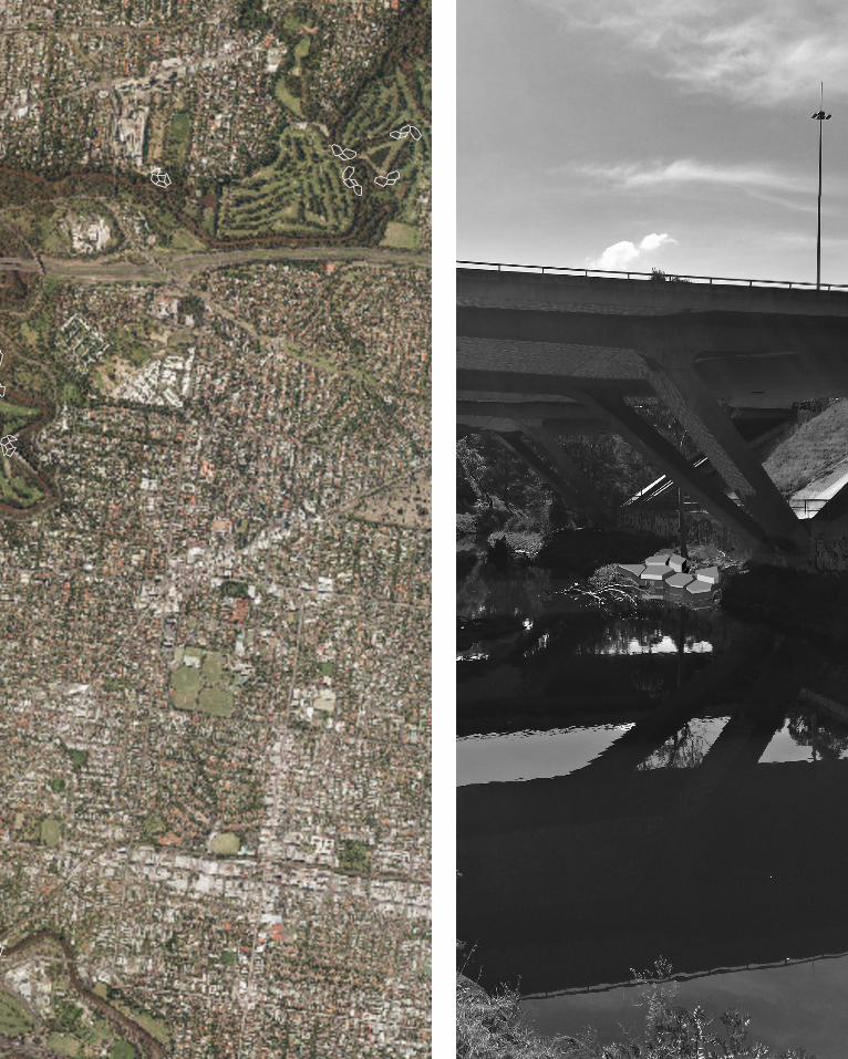
SITE JUSTIFICATION
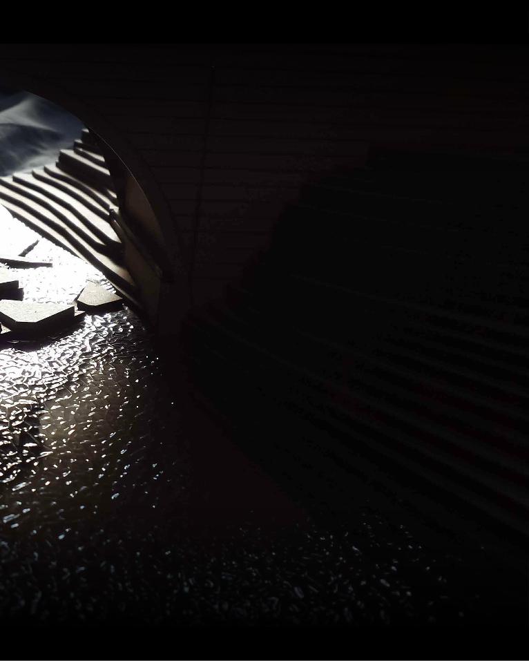
In my crit it was suggested that the location was undesirable or inappropriate for recreational use on the grounds that it would just be too unpleasant for people to want to pause and hang around. Whilst I agree that at present the site is not in a great condition, I’d suggest that the site is intriguing and does have inherent beauty. The bridge, both aesthetically and functionally, was an important reason for choosing the VLWH��,�WKLQN�WKHUHV�DSSHDO�LQ�LWV�GLJQLHG�DQG�KLVWRULF�IRUP�alone. Standing under it is one of the only points in this stretch of trail where site users get an uninterrupted view along the water because of the density of the trees, which is also an appealing aspect of the site. The way the light refracts off the water casts delicate, dynamic patterns on the barrel of the bridge that are quite captivating and make the space interesting to observe. The variable angle of the sun in the sky as the seasons change also mean that the bridge provides shade in the summer but its underside is well let in winter, which is ideal in terms of thermal comfort needs.
FIG.30 (LEFT): SITE PLAN.FIG. 31 (RIGHT): LIGHT PLAYING ON UNDERSIDE OF BRIDGE.
FIG.32 (BELOW): VIEW ALONG RIVER FROM UNDERNEATH BRIDGE.

68 PROJECT PROPOSAL
APPLICABILITY BEYOND MY CHOSEN SITE
FIG.33 (IMMEDIATE RIGHT): MAP OF STUDLEY PARK REGION WITH SUGGESTIONS OF WHERE ADDITIONAL FILTER SYSTEMS COULD GO (NOT TO SCALE).FIG. 34: (FAR RIGHT): DEMONSTRATION OF FILTRATION SYSTEM APPICABILITY TO ANOTHER ENVIRONMENT.
:KLOVW�WKH�FRQJXUDWLRQ�RI�WKH�9RURQRL�FHOOV�LQ�P\�SURSRVDO�KDV�EHHQ�FKRVHQ� IRU� LWV�VSHFLF� IXQFWLRQDOLW\�DW� WKH�SRLQW�where Heidelberg Road crosses Merri Creek, the principle behind the system is much more broadly applicable. 7KH� OWUDWLRQ� V\VWHP� LV� DSSURSULDWH� IRU� ZDWHUZD\V�throughout urban environments and could be implemented systematically along others such as the Yarra River and the Maribyrnong River. Intersections of waterways and roadways as well as stormwater drains are key sites where OWUDWLRQ�V\VWHPV�VKRXOG�EH�SODFHG��EHFDXVH�WKH�LQFLGHQFH�of pollution here is much higher. Bends in waterways are also key areas for consideration. Water must slow down as it follows bends, which means there is naturally a process of aggradation of sediment and litter at these points.
The aerial view of Melbourne in Figure X demonstrates where IXUWKHU�OWHUV�FRXOG�EH�SODFHG��3OHDVH�QRWH�WKDW�WKH�9RURQRL�diagrams overlain on the photo are representative only of a proposed location, they do not represent a proposed FRQJXUDWLRQ�
PROJECT PROPOSAL 69
70 PROJECT PROPOSAL
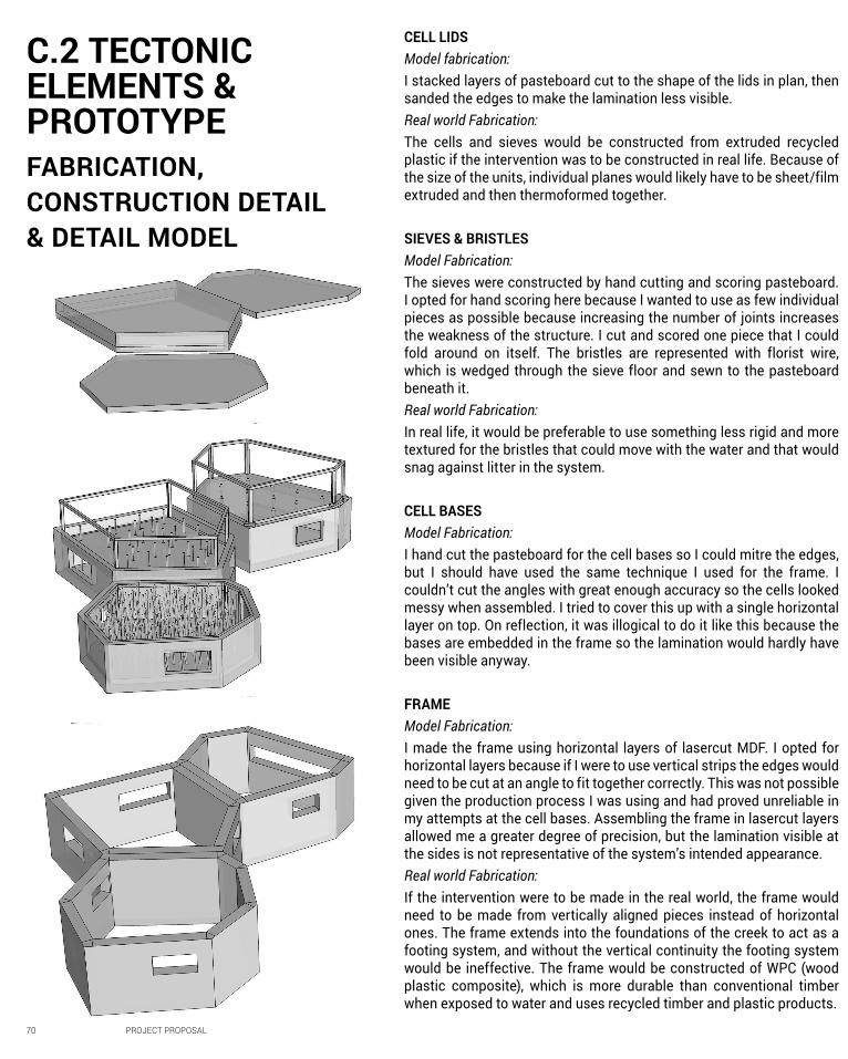
FABRICATION, CONSTRUCTION DETAIL & DETAIL MODEL
CELL LIDSModel fabrication:I stacked layers of pasteboard cut to the shape of the lids in plan, then sanded the edges to make the lamination less visible. Real world Fabrication:The cells and sieves would be constructed from extruded recycled plastic if the intervention was to be constructed in real life. Because of the size of the units, individual planes would likely have to be sheet/film extruded and then thermoformed together.
SIEVES & BRISTLESModel Fabrication:The sieves were constructed by hand cutting and scoring pasteboard. I opted for hand scoring here because I wanted to use as few individual pieces as possible because increasing the number of joints increases the weakness of the structure. I cut and scored one piece that I could fold around on itself. The bristles are represented with florist wire, which is wedged through the sieve floor and sewn to the pasteboard beneath it. Real world Fabrication:In real life, it would be preferable to use something less rigid and more textured for the bristles that could move with the water and that would snag against litter in the system.
CELL BASESModel Fabrication:I hand cut the pasteboard for the cell bases so I could mitre the edges, but I should have used the same technique I used for the frame. I couldn’t cut the angles with great enough accuracy so the cells looked messy when assembled. I tried to cover this up with a single horizontal layer on top. On reflection, it was illogical to do it like this because the bases are embedded in the frame so the lamination would hardly have been visible anyway.
FRAMEModel Fabrication:I made the frame using horizontal layers of lasercut MDF. I opted for horizontal layers because if I were to use vertical strips the edges would need to be cut at an angle to fit together correctly. This was not possible given the production process I was using and had proved unreliable in my attempts at the cell bases. Assembling the frame in lasercut layers allowed me a greater degree of precision, but the lamination visible at the sides is not representative of the system’s intended appearance.Real world Fabrication:If the intervention were to be made in the real world, the frame would need to be made from vertically aligned pieces instead of horizontal ones. The frame extends into the foundations of the creek to act as a footing system, and without the vertical continuity the footing system would be ineffective. The frame would be constructed of WPC (wood plastic composite), which is more durable than conventional timber when exposed to water and uses recycled timber and plastic products.
C.2 TECTONIC ELEMENTS & PROTOTYPE

PROJECT PROPOSAL 71
FIG.35: UNDERSIDE OF LID IN DETAIL MODEL.
FIG.36: SIEVE BLOCKS CONSTRUCTION DETAIL.
FIG.37: DETAIL MODEL OF SEVERAL CELLS COMPRISING THE SYSTEM.

72 PROJECT PROPOSAL
CONSTRUCTION DETAIL & USER INTERACTION3ULPDULO\�� WKH� GHVLJQ� LV� D� OWUDWLRQ� V\VWHP� WKDW� UHTXLUHV�active participation by community groups to maintain. As such, I tried to design the system in a way that could easily be navigated by a couple of people. Sieves sit permanently in the cells and are lifted upwards during cleaning, combing out rubbish that has collected in the cells. This prevents users from having to rummage through the water in the cell and pick pieces of litter out from between the bristles. There are small subtractions from the corners of the sieve frames in which blocks can be placed to keep the sieves suspended whilst they are being emptied.
Through it’s peculiarity in the landscape, the intervention will naturally attract curiosity. This is an opportunity to bring to the attention of site users information about the FUHHN�DQG�WKUHDWV�WR�LW��DV�ZHOO�DV�VSHFLF�LQIRUPDWLRQ�DERXW�WKH�OWUDWLRQ�V\VWHP��WKH�ELRPLPHWLF�SULQFLSOHV�RQ�ZKLFK�LW�was based and directories on how to become involved with the maintenance. On the lids of the cells will be QR codes which will lead to a website providing information on these topics. I thought a website would be preferable to a static sign because it can more easily be kept up-to-date.

PROJECT PROPOSAL 73
FIG.38 (ABOVE, TOP): SEQUENCE SHOWING OPERATION OF SIEVES.FIG. 39: SECTION THROUGH BRIDGE..

74 PROJECT PROPOSAL
SITE MODEL & DETAIL MODEL
C.3 FINAL MODEL

PROJECT PROPOSAL 75
FIG.39 (LEFT): SITE MODEL IN PLAN, BRIDGE REMOVED.FIG.40 (RIGHT, ABOVE): DETAIL MODEL, CLOSED AND OPEN.
FIG.41 (RIGHT, BELOW): SITE MODEL IN PERSPECTIVE.FIG.42 (NEXT PAGE): VIEW LOOKING NORTH UNDER THE BRIDGE.

76 PROJECT PROPOSAL
PROJECT PROPOSAL 77

78 PROJECT PROPOSAL
C.4 ADDITIONAL WORKCREEK WATER LEVEL & FILTRATION CELL APERTURES
MEAN LEVEL OF MERRI CREEK 2010 - 20151
Day of the YearBand indicating values that would fall within opening
dimensions ranging from 0.2m - 0.5m above creek level
1 MELBOURNE WATER, ‘RAINFALL AND RIVER LEVEL: NORTHCOTE’ (2015) < HTTP://WWW.MELBOURNEWATER.COM.AU/WATERDATA/RAINFALLANDRIVERLEVELDATA/PAGES/RAINFALL-AND-RIVER-LEVEL-NEW.ASPX> [ACCESSED 23 MAY 2015].
Band indicating values that would fall within opening
dimensions ranging from 0.1m - 0.9m above creek level
8SRQ�UHHFWLRQ�RQ�WKH�3DUW�%�FULW�,�UHDOLVHG�LW�ZRXOG�QRW�EH�advisable to narrow the openings vertically as I originally intended because that would mean there are times when water would be stagnant in the system as creak levels change. As such, the apertures could only be made smaller horizontally.
Melbourne Water record information on rainfall and water levels for various waterways in Melbourne. Unfortunately, WKHUH� ZDV� QRW� D� GDWD� FROOHFWLRQ� SRLQW� DW� P\� VSHFLF� VLWH��but there was one approximately one kilometre upstream at a comparable site in Northcote. I used the information to approximate what proportion of time the water level of the creak would fall within the aperture dimensions of the system.
Present dimensions only allow for water entry 79.4% of the WLPH�� 7KLV� H[FOXGHV� WLPHV� RI� VHYHUH� RRGLQJ� ZKHQ� OLWWHU�pollution is highest and, theoretically, it is most important that the system is operating.
6LJQLFDQW�HQODUJHPHQW�RI�RSHQLQJV�FHOOV�ZRXOG�PHDQ�WKH�platform has to be elevated. It was important to the design that the platform was a level between the pedestrian path and the water because it makes the Creek more immediate and encourages greater engagement, but if the thrust of my design is functional it didn’t make sense to compromise that functionality for some symbolic design intention.

PROJECT PROPOSAL 79
0.0M
0.2M
0.5M
Creek Bed
Min. Entry
Max. Entry
79.4%
11.2%
9.4%
the percentage of
days with creek water
levels that lie within the
initial proposed filtration
cell opening dimensions
the percentage of days
with water levels that exceed
the maximum height of the
filtration cell openings
the percentage of days
with water levels that do not
meet the minimum height of
the filtration cell openings

80 PROJECT PROPOSAL
CHANGING APERTURE DIMENSIONS TO INCREASE FUNCTIONALITY
After assessing the functionality of my initial system dimensions against the water levels of the creek, it became apparent that it was necessary to increase the dimensions of the apertures. By increasing the size of the openings from 0.3m to 0.8m, the percentage of time for which the mean height of the creek sits within the system apertures increases from 79.4% to 95.7%. This is achieved without greatly increasing the height of the frame, which still allows for a difference in levels between the pedestrian path and WKH�OWUDWLRQ�V\VWHP�
The varying height of the lids is intended to accommodate people using the site as chairs and tables. There are three KHLJKWV�� 2QH� KHLJKW� VLWV� XVK� ZLWK� WKH� IUDPH�� DQRWKHU� LV�0.25m taller than the frame; another is 0.5m taller than the frame. Each cell is surrounded by 0.2m of frame, so where two cells abut one another there would be a gap of 0.4m. This distance is intended to be a comfortable distance to walk between but also a safe distance to bridge if stepping from lid to lid.
FIG.43 (ABOVE): NORTH ELEVATION.FIG. 44 (RIGHT): DIAMGRAM SHOWING FINAL HEIGHTS OF CELLS, FRAME AND APERTURES.

PROJECT PROPOSAL 81
0.25M
1M
0.5M
0.8M
95.7% the percentage of days
with creek water levels that
lie within the revised filtration
cell opening dimensions

82 PROJECT PROPOSAL
Whilst I think my project was very simple relative to what VRPH�RI�P\�SHHUV�KDYH�SURGXFHG��,�GR�WKLQN�LW�VDWLVHV�PRVW�of the learning objectives.
0\� OWUDWLRQ� V\VWHP� LV� UHHFWLYH� RI� GHVLJQ� ZRUNRZV� LQ�the age of optioneering. I chose a computational design tool appropriate to the function of my design vision (Voronoi diagram – biomimetic in its own way, but that also geometrically made sense to employ because it easily builds indirect pathways), used CAD tools to develop various LWHUDWLRQV�� XQGHUWRRN� GLJLWDO� VLPXODWLRQV� DQG� WKHQ� UHQHG�my proposal based on the outcomes of these simulations. Iterations were produced by altering key parameter inputs for the Voronoi diagram in grasshopper and by selecting from these the proposals that possessed qualities shown to be most effective through my Maya simulations.
Granted I was starting from a very low base, but I do feel this subject has really forced me to extend myself and my technical abilities. I’ve been forced to explore various digital design tools, most notably Rhino and grasshopper, and have GHQLWHO\�LQFUHDVHG�P\�FRPSHWHQF\�LQ�WKHP�DV�D�UHVXOW��
The analytical diagramming component of this subject has been of particular interest to me. Design is fundamentally about communication, and the best idea in the world won’t be convincing if it is not conveyed in an approachable and persuasive manner. I believe practicing analytical diagramming in this subject has improved my ability to communicate my ideas by forcing me to break things down into their salient points and to explain those points in a logical sequence. I think this relates closely to the impact that Grasshopper itself as a visual programming language has had on my thought process. At the beginning of this
C.4 LEARNING OBJECTIVES & OUTCOMES

PROJECT PROPOSAL 83
semester Grasshopper was visually so confronting and incomprehensible to me, but I think it has forced me to understand simple objects (eg. a circle) in more complex terms (eg. circle as a combination of plane of alignment, origin point, radius etc). It has helped me to understand to a greater extent the relationships between components of a whole.
As a result of attempting to fabricate part of my models by KDQG��,�DP�GHQLWHO\�VROG�RQ�GLJLWDO�IDEULFDWLRQ��7KH�SUHFLVLRQ�of digital fabrication is unparalleled by that of manual models. However, in Part A it was so forcefully emphasised that part of digital fabrication’s lure is the speed it brings to design and the potential it has to increase the pace of the design process. This was not my experience. Obviously if I ZHUH�ZRUNLQJ�DW�D�ODUJH�GHVLJQ�UP�ZLWK�DQ�LQ�KRXVH�GLJLWDO�fabrication unit things would be different. But we had to book an appointment a week in advance at the Fab Lab to get a
consultation for 3D printing, and laser cutting took 4 days when I was submitting my job. I made part by hand because it was quicker than digital fabrication. I would argue that digital fabrication at university just changes the loading of the design process to make the beginning much more top heavy because it requires so much more preparation.
I still feel limited in terms of what I can produce using computational techniques. But maybe part of the lesson is that parametric design is not appropriate for every situation.
Going forward, I feel greatly advantaged by being exposed to the computational design techniques in Studio Air. It has expanded my imagination, my ability to engage critically with the built environment and my faculty for design conceptualisation, not to mention provided me with real technical skills.

84 CONCEPTUALISATION
Melbourne Water, ‘Rainfall and River Level: Northcote’ (2015) < http://www.melbournewater.com.au/waterdata/rainfallandriverleveldata/Pages/Rainfall-and-river-level-new.aspx> [accessed 23 may 2015].
C.5 REFERENCE LISTTEXT SOURCES
IMAGE SOURCES
FIGURE 33: Aerial photograph of Melbourne, retrieved from <http://services.land.vic.gov.au/maps/mpmo.jsp> [accessed 15 June 2015].