Latrine Logger - Data Acquisition Unit · Latrine Logger - Data Acquisition Unit Date: 19/06/14...
15
Latrine Logger - Data Acquisition Unit Date: 19/06/14 Version: 1.0 By: Matt Little The LatrineLoggger is an Arduino data acquisition unit which stores data to an SD card (as a .csv file). It uses a real time clock with a back-up battery for accurate data logging and time-stamping. It uses a 555 timer circuit with a capacitance sensor to read when 'flushes' occur in a plastic pipe. The change in capacitance is detected and the length of the flush is measured. This data is written to an SD card in human readable format for analysing later. It is designed to be low-cost, robust and easy to install. This was developed by James Fowkes, Nicola Greene and Matt Little for Water For People. It utilises an Arduino UNO brain. Note: This requires an FTDI USB to serial 3V3 cable for programming. Note: This requires 3 x D cell batteries and an SD card (8Gb size best). Parts required: There are three main parts: • The main logger unit • The sensor • The sensor cable
Transcript of Latrine Logger - Data Acquisition Unit · Latrine Logger - Data Acquisition Unit Date: 19/06/14...

Latrine Logger - Data Acquisition Unit
Date: 19/06/14 Version: 1.0 By: Matt Little
The LatrineLoggger is an Arduino data acquisition unit which stores data to an SD card (as a .csv file). Ituses a real time clock with a back-up battery for accurate data logging and time-stamping.It uses a 555 timer circuit with a capacitance sensor to read when 'flushes' occur in a plastic pipe.The change in capacitance is detected and the lengthof the flush is measured.This data is written to an SD card in human readable format for analysing later.
It is designed to be low-cost, robust and easy to install.
This was developed by James Fowkes, Nicola Greene and Matt Little for Water For People.
It utilises an Arduino UNO brain.
Note: This requires an FTDI USB to serial 3V3 cable for programming.Note: This requires 3 x D cell batteries and an SD card (8Gb size best).
Parts required:
There are three main parts:• The main logger unit• The sensor• The sensor cable

You will also need:• a high quality SD card with a capacity 4Gb or greater.• 3 x high quality D size batteries• A Philips/cross-head screwdriver
You may also need (not supplied):• a computer with the Arduino IDE installed • a FTDI USB to serial cable with code: TTL-232R-3V3, such as this:
Available here (among other places): http://www.ftdichip.com/Products/Cables/USBTTLSerial.htm

Installation:
Step: 1 Wrap the sensor around the waste pipe
Unfold the sensor carefully – it contains sensitive electronic connections.Wrap around the waste pipe.Close the velcro strap to ensure a good fit.
Step: 2 Plug in sensor cable

The sensor cable goes from the sensor to the main logging unit.The plug/socket on the sensor is notgreat, so please be careful here.
Plug into the main logging unit – ensure the pins match up.
Ensure the locking ring is locked.
Ensure the cable is kept free of any snags and is firmly attached. Use cable ties if possible.
Step: 3 Insert batteries

Open the main logger box with a cross head/Philips screwdriver.
Ensure the unit is switched OFF.
The unit requires 3 x D cell batteries. Use good quality batteries (Duracell, Everready) only.
Ensure correct polarity (check battery boxes)
Step: 4 Insert an SD Card
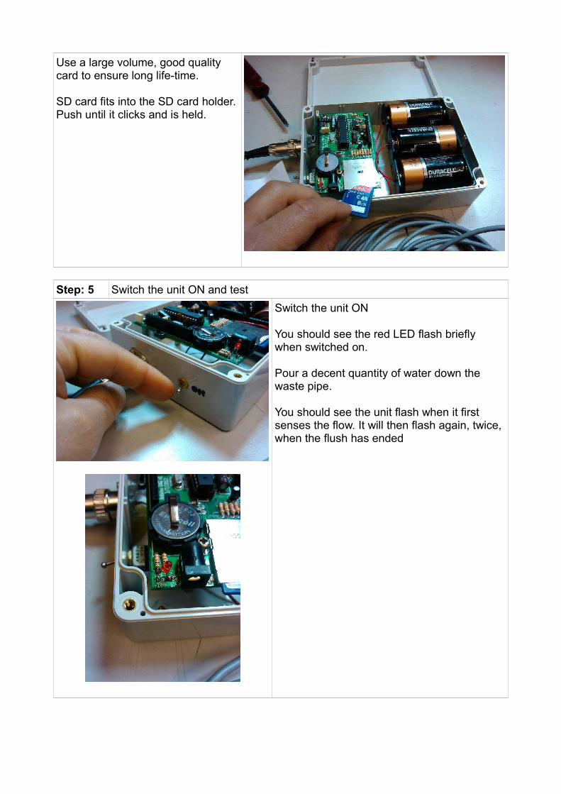
Use a large volume, good quality card to ensure long life-time.
SD card fits into the SD card holder.Push until it clicks and is held.
Step: 5 Switch the unit ON and test
Switch the unit ON
You should see the red LED flash briefly when switched on.
Pour a decent quantity of water down the waste pipe.
You should see the unit flash when it first senses the flow. It will then flash again, twice, when the flush has ended

Step: 6 Check Data is OK
Follow the 'Data Download' instructions.
Check data is being recorded OK.
If not:Check cable connected correctly and SD
Step: 7 Leave to monitor
Unit should not need any intervention, but checking the data regularly for testing is sensible.
Data download:
Step: 1 Switch the unit OFF
Its always best to switch the unit OFF when removing or inserting the SD card.

Step: 2 Remove the SD card
Push the SD card slightly in and it will then release and spring slightly out.
Step: 3 Insert the SD card into a computer
You might need USB to SD card converter. A lot of computers have them built in.
Step: 4 Load data

If using Windows:You will get a pop up 'AutoPlay' box.
Click on 'Open folder to view files'
You will see a list of the files (one is created each day, unless there was no data).
Step: 5 Check data is valid
Double click on the file and it should open with Excel, or some spreadsheet program.
You can also open the spreadsheet program and navigate to open the file from there.
When the data opens you might see some data is shown as ### symbols. This is due to the fact it is too big for the data holder.
Select everything and then double click on one of the vertical lines. This will auto size thecells and all the data should be visible.
Data is in human-readable format, with the flush time, the duration in seconds and the battery voltage.
If the battery voltage is below 3.3V then the data might not be valid due to power supply issues.

Step: 6 Remove SD card
Always ensure you use the 'Eject Disk' function.
Never just remove the disk as this could cause data corruption.
Calibration and setup:
This is more detailed information for changing the time, date and reference and also uploading new programming code into the Arduino. For information only.
Step: 1 Switch OFF the unit
Step: 2 Plug in the FTDI cable
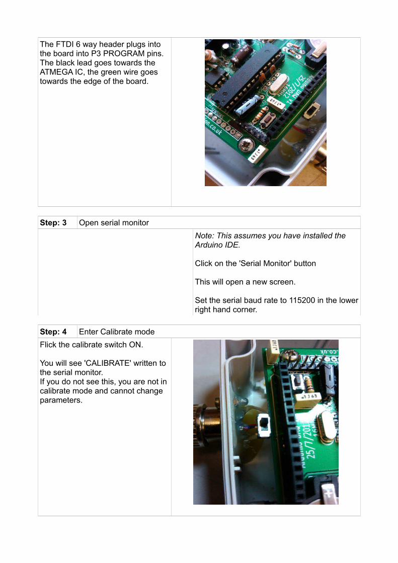
The FTDI 6 way header plugs into the board into P3 PROGRAM pins.The black lead goes towards the ATMEGA IC, the green wire goes towards the edge of the board.
Step: 3 Open serial monitor
Note: This assumes you have installed the Arduino IDE.
Click on the 'Serial Monitor' button
This will open a new screen.
Set the serial baud rate to 115200 in the lowerright hand corner.
Step: 4 Enter Calibrate mode
Flick the calibrate switch ON.
You will see 'CALIBRATE' written to the serial monitor. If you do not see this, you are not in calibrate mode and cannot change parameters.

Step: 5 Change Date
Write DxxxxxxE, where xxxxxx is DDMMYY, DD is the date (eg. 2nd is 02), MM is the month (eg. May is 05) and YY isthe year (eg. 2014 is 14)
Send this to the device.
This will return the correct stored date. Double check this is correct.
Step: 6 Change Time
Write TxxxxxxE, where xxxxxx is HHMMSS, HH is the hour (eg. 2pm is 14), MM is the minutes (eg. 5 mins past is 05) and SS is the seconds.
It is best to set the time to a 'whole' number of seconds slightly in the future (say 14:30:00, when the time is actually 14:29:37), write this into the serial send screen (but do not send).Open a clock on screen and wait until it is exactly 14:30:00.
Press send at exactly that moment to update.

This will return the correct stored time. Double check this is correct.
Step: 7 Change Reference
Write RxxE, where xx is a reference number from 00 to ZZ. This can be done when there are lots of units and you wouldlike to keep a different reference in each one.
I would adjust this once, write it on the unitand never change it.
This is written into the data, which might be useful for future data processing.
Step: 8 Check data
Switch OFF calibrate mode (set switch back).
You can fake a 'flush' by putting your hand into the sensor.You should see the words 'Flush Started...) when you put your hand in.When you remove your hand, you should see 'Flush finished. DurationX seconds'.
Then the data written to the SD card will appear as a text string.
The data will appear at 115300 baud to the serial.
Step: 9 Upload new program
WARNING: Only perform this if you know what you are doing. You can potentially render the unit useless if this is not done correctly.
Open the new 'sketch' within the Arduino IDE.
Click on the 'Upload' button.

Wait for the Arduino IDE to say 'Done Uploading'
Check the function of the new program, asrequired.
Technical information:
Please see this list for the Arduino pin allocations:
Pin Number
Type of data
Allocation
D0 Digital Serial Rx
D1 Digital Serial Tx
D2 Digital Clock interrupt at 1 second
D3 Digital Available
D4 Digital LED indicator
D5 Digital 555 timer frequency monitoring
D6 Digital SD card - Card detect
D7 Digital Calibrate switch
D8 Digital Available
D9 Digital Available
D10 Digital SD card - Chip select - Cannot be used
D11 Digital SD card - MOSI - Cannot be used
D12 Digital SD card - MISO - Cannot be used
D13 Digital SD card - Clock - Cannot be used
A0 Analogue Battery Voltage
A1 Analogue Available
A2 Analogue Available
A3 Analogue Available
A4 Analogue RTC - SDA - Cannot be used
A5 Analogue RTC - SCL - Cannot be used
Arduino code information:
Some example code, including the main Latrine Logger program is available at www.re-innovation.co.uk, via the GITHUB account.
Overview of the code:
A PCF8563 Real Time Clock is used to timestamp the data. Each logger has a reference (user adjustable from 00-99 & AA-ZZ).

Data is written to a .csv file created on an SD card.A new file is created each day. If file alreay present then data is appended.The file name is created from the reference number and the date in the format:RXXDXXXX.csv, where RXX is the reference number and DXXXX is the date in the formatDDMM.
Data is stored with human readable headers:"Reference, Time, Date, Flush Duration,Vbattery"
As mentioned in the set-up instructions:You can adjust the parameters of the device using serial commands. These parameters are stored in EEPROM.These are:
1. R??EThis will change the reference number to ??
2. T??????EThis will change the time to HHMMSS
3. D??????EThis will change the date to DDMMYY
Flow diagram of code:
****TO DO****
Contact details:
Renewable Energy [email protected]
Hopkinson Gallery21 Station Street
NottinghamNG7 6PD
Please email [email protected] with any questions or comments.
More technical information can be found via www.re-innovation.co.uk.
Circuit schematic: