LATHE BED DESIGN - archive.org
51
PRICE 25 CENTS I* LATHE BED DESIGN A REVIEW OF THE HISTORY, DEVELOPMENT AND PRESENT PRACTICE IN THE DESIGN OF LATHE BEDS BY JOSEPH C. HORNER MACHINERY'S REFERENCE BOOR NO. Ill PUBLISHED BY MACHINERY, NEW YORK
Transcript of LATHE BED DESIGN - archive.org

PRICE 25 CENTS I*
LATHE BED DESIGN A REVIEW OF THE HISTORY, DEVELOPMENT AND
PRESENT PRACTICE IN THE DESIGN OF LATHE BEDS
BY JOSEPH C. HORNER
MACHINERY'S REFERENCE BOOR NO. Ill PUBLISHED BY MACHINERY, NEW YORK
MACHINERY'S REFERENCE BOOKS
This treatise H one unit In a corner eh*-naive Series of Reference hooks originated
by Machinery, and including an indefinite number of compact units, each covering
one subject thoroughly The whole series comprises a complete working library
of mechanical literature. The price of each hook is 25 cents (one shilling) de¬
livered anywhere in the world,
LIST OP REFERENCE BOOKS
No, 1, Worm Gearing.—Culeulu ting Dlmmalun*: El<it**; Location of Pitch turtle. Self Looking Worm Gearing. tic.
No. 2, Hiiftlng: ttoum Fraotica,—System*: Trse- Inf, Leltertaf and Mounting.
No. 8. Drill Jlga.—Principle* of Prill Jlg»T Jig Plate*; Kxaiuple* of Jlga.
No, 4, Milling FUtorii**—Principle* of fl*. tori', Ptaiitpli’i' of lie*L|£ii,,
No, 3, f trvt PftmMplof of Tbmrtlitit Meehan Jus,
Na, 0. Pit nd a. ml DU Work,—Priori [tic* of Ptmeb iihI* I Hi* Work' kinking mol Using I Hr*; Hu and Puteb Design.
No, 7, Latte ami Planer Tool**—Cutting Tool*: Hiring Toni* Kf*n r«i of Kintulard Simp FWntlng Tt*d*,
No, 8* Working Drawing* anil Drafting-Roora Kmlu,
No, ft* Designing ami Cutting Cam*.—Dmfling t*f Cttioo, Cam Curves. Cam Design aud Cam Catliagp
No, 10, Examples of Machin* Shop Froctla*. Cutting Jtevvl Geur*; Making u Worm-Gear; Spindle Cons trin tlutt,
No. 11. Bearing*.—Design of Bearing*; Can**-* nf lint Bvirlain. Alloy * for Bearing*. Friction amt Lull flea tkm.
No* tft* Out of prltiL
No, 18, Blanking Dloi,—Making Blanking Hie*: Planking a ml Piercing Hies; Split Dies. Novel MeUe in IHe Making,
No, 14* Details of Machine Tool Design.—Cone „ Pulley a tt oil tutu: Strength of tkomtcrshiifU; Tumbler Gear iVsign, Paulin of Iron Castings,
No. 18, Spur Osorlng,—PJnirnMvnN; Design; Strength; Dumb Lilly.
No* 18* Machine Tool Drioei.—Speed* amt FWd*; single Pulley Drives; Drlrra for High Speed Cutting Tool*.
No* IT# Strength of Cylinders.—Format**, Clmrta, and Diagram*.
No* 18. Shop Arithmetic for the Machinist,— Tjtfwra; Chung" Gears; Cut* Jug Speed.*; Feeds; indexing* Gearing for Cnltlng spiral*. Anglos,
No, 18* Hie of Formalas In Mechanics,—With numerous applications
No* 20* Spiral Gearing.—ItatM* Formula** and Diagram** etc.
No* 8L IfaMttria^ Tools.—R|*lory of Standard ilraaufement*; Call pen; comp* **♦'*. Micrometer Tuib; Pmtrarjors.
No Sfft, Calculilloa of Elam rata of Markin* IV algm-Vmciut *U Safety : Striuigth **f Dolt- Riser *4 jAiuts S*y* anil tUy stays^^ggl*' joriM»,
^BfcaUl* hark go % a
No. 21, Theory of Oru« Deaign,—Jth Crwoee; Shafts, Lie*r», and Rearing*; Force to Mono Crane Trolley*; Pillar Cranes.
No. 24* Examplca of Calculating Design*.— Clluft* In Dralgulug; Punch and Riveter Frames. Slmar l‘rimn-p; Billet nod Par Panovs, etc,
No. 2fi. Deep Hole Drilling.—Mi-HukI* of Hr til tug; Construction of Hriii*.
No. 30, Modern Fufivli ami Dio Cvftstrutrtloa,— rofmtruetlon Olid |!m> of rojiiprcw* Hies; IPideru Blanking (Hr Con strum km; Drawing and Conning Die*.
No* 87, Locomotive Design. Pari L—Holler* t y linden* Pipe* ami IVfimt
No, 2i, I*ol a motive Design, Furl El —Stephen* «ni nnd \\ nlmliiivru Valve Motion*: Theory* Cal vtllatlou itin) tK'sIgii*
No, 28. LoootiLoUvrv Design, Part III —ftnudee ima; Iflibauat Pipe; Franu**; Cme* iiends; Gnld* hare; fV»rmvvtlng-n*ur Crank-pins; All**; Driving Vi beet*,
No. 88, LooomatiTe Deaign* Part 1Y.—Springs, Track*, Cat* ami Tender.
No. 31, Ben?* Thread Tools and Gage*.
No. 82. Screw Thread Cutting,—ImtUn Change Gram; Thread Trail*; Kink*.
No, 83, Syittnta and Ffmelico of tho Draftings Room*
Ha. 34. Caro ami Repair of Dynamo* and Motors.
No, 3fi. Taklss and Formulas far Shop and Drafting-Room,—77ie Csv bf Furfiuilas, K^lutlvu »»f Trio tig le* I Kir vug th uf Msterini*; Gearing, Krrew Thread*; Tap HrltU; Drill Ktrca; Tupors; Ki jfl, i‘tc.
No, 38, Iron and Stool,—Principle* of Mnmi failure and ireatment.
No. 37* Etvsl Gearing, -Rule# aod Fnrnmlus; Ksamplva *4 CaleutoHoii. Tootli Outlines; Strength and Huroh iilty , HcaJgu; Ala Diode af Cutting Tcidh.
No* 38. Out uf print, See No. fl8.
No. 38, Fans, Yeali)«tl0li and Heating*—Fans; lie* left; Shop Ilia ting.
No. 40, Fly* Wh oela. —Tliel f PuftJOno* Cilcfilk Hun and Itaulgn.
No, 41, Jig* and Fixtures, Part L—Prlaetpl^r of Design, Drill Jig lluiiblugs; Lueatlng IVdnWi Clnniplug HcYleeu*
No, 43, Jig* and Fixtures* Part tl*—Open and Ctowed Drill digs,
No, 41* Jjg* and Fliturra* Pari 111*— Ikurlng ami Mill mg Future*
No* 44, Kaolins filaekaniilllng,— fly items. Tool* and Mmcklava uasd.
for addition*! utlesl
r

MACHINERY'S REFERENCE SERIES EACH NUMBER IS ONE UNIT IN A COMPLETE LIBRARY OF
MACHINE DESIGN AND SHOP PRACTICE REVISED AND REPUBLISHED FROM MACHINERY
NUMBER 111
LATHE BED DESIGN By Joseph G. Horner
: CONTENTS-... • * » • *** •'*
The Sections of Lathe Beds ------ 3
The Longitudinal Forms of Lathe Beds - - - 37
Copyright, 1918, The Industrial Pro—, Publisher* of llAGBimi
49-66 Lafayette Street, New York City


CHAPTER I
THE SECTIONS OP LATHE BEDS
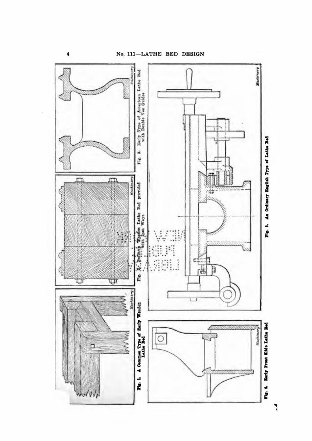
All the early lathe beds were made of wood. Engravings showing some of these wooden beds may be seen in old works on turning. They are to be found now only in some of the lathes used by wood-turners, and in some pattern-shops, although in the latter case, lathes with iron beds are now almost exclusively used. Fig. 1 shows a wooden lathe bed or stand. Different methods were used for attaching the bearers or shears to the uprights. At a very early date the wear of the top surfaces of the wooden bearers was prevented by screwing thin fiat iron plates onto them. Strips of wrought iron were also fitted, having curved edges chipped and filed to shape, as shown in Fig. 2. There was not a great deal of durability in these shears, but the chief objection to this construction was that when the timber warped, as it was bound to do in the course of time, it pulled the iron strips with it, and threw the headstock, tailstock, and rest out of alignment
The first all-iron beds were of triangular section, the form prob¬ ably originating with Henry Maudslay. The bed was built of two bars of triangular section, secured in brackets bolted onto the legs. There was a very good reason for the adoption of this form of bed in pref¬ erence to any other. There were no planing machines at that period— in the latter part of the ^htefcnfh/cebth/y^-rSO rthat it was an impor¬ tant consideration to be. able, tor teduqje 'Capping and filing to a minimum on a single bar. 9eside^.lf the, tyro upper faces were true, it made no difference whether the: botConu^ne was true or not, because there was clearance between it. and, the tailstock and rest
Lathe beds with a single: of .triangular section have often been built, although they are' seldom sedn rfow, except in the lathes used by watch- and clock-makers. These beds are sufficiently rigid for light duty, and chips do not lodge on them. The triangular-section lathe bed also possesses the virtue of insuring self-alignment of the tailstock and rest, which bear on the upper edges only. The essentials of the triangular bar section have been revived and perpetuated in the Pittler bed—referred to later—but in a modified and stronger, stiffer, and steadier form. The Pittler bed consists of a bar of trapezoidal section. The bar is hollow, and the lead-screw, passing through the hollow section, is thus protected. In some watchmakers’ lathes, the essential features of the triangular bed are retained, but the lower side is of convex form. Some lathe beds are of cylindrical cross-section, either solid or hollow. All these types are simply variations of the single bar type, and are illustrated later in this treatise. Mention may also be made of square and rectangular beds, the latter being employed in a few of the peculiar French lathes used for screw threading.

LATHE BED DESIGN 6
Early Development of Lathe Beds
Since a single triangular bed was not stiff enough to resist the torsional stresses of heavy cuts, which produce vibration and cause the bed to spring, an early development was that of using two deep parallel bars or beam sections, cast separately and bolted together. In the next stage the two bars were cast in one piece with connecting ribs. It was still, however, necessary to reduce the labor of chipping and filing to the least amount consistent with the practical require¬ ments of the time; hence the form shown in Fig. 6, in which the top vees of the triangular bars were still retained, represented standard practice, with or without the internal stiffening ribs which were cast to increase the rigidity in the lateral direction. Then modifications of the design in Fig. 6 were introduced as shown in Fig. 7, where one vee is dispensed with, but the other retained for guidance. In Fig.
8, the width of the flat bearing surface is increased. This type of bed also made it easier than with two vees to fit the parts to a nicety. This construction is, for the same reason, employed instead of two vees in many lathes and grinding machines to-day. At last both bearing faces were made flat as shown in Fig. 9, and the longitudinal means for guidance offered by the vees was, therefore, abandoned. The lateral play was then prevented by making tenons on the heads fit between the edges of projecting internal ribs, as shown in Fig. 9. All finished surfaces were still kept narrow, however, until, after the Invention of the planer, they developed into the present forms.
As the slide-rest developed, the battle of the vees and flats became intensified. The older upstanding vees are still retained—with modi¬ fications—as the only guiding elements in standard American practice. At a comparatively recent date slight modifications have been made in some forms, in which a flat is combined with the vees; but the principal difference which exists even now is that of using either two or four distinct vee-ways. In the latter design. Fig 3, the two inner
6 No. Ill—LATHE BED DESIGN
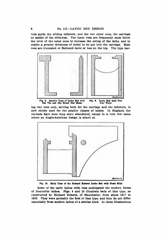
vees guide the sliding tailstock, and the two outer ones, the carriage or saddle of the slide-rest The inner vees are frequently sunk below the level of the outer ones to increase the swing of the lathe, and to enable a greater thickness of metal to be put into the carriage. Both vees are truncated or flattened more or less on the top. The type hav¬
ing two vees only, serving both for the carriage and the tailstock, is now chiefly used for the smaller classes of lathes. In England, the vee-beds have been long since abandoned, except in a very few cases where an Anglo-American design is aimed at
Some of the early lathes with vees anticipated the modern forms of front-slide lathes. Figs. 4 and 10 Illustrate beds of this type, as constructed by Richard Roberts, of Manchester, from about 1817 to 1820. They were probably the first of that type, and they do not differ essentially from modern lathes of a similar kind. In these illustrations

LATHE BED DESIGN 7
two variations are shown. In one, dependence is placed on the guid¬ ance of one vee only, and the lower edge of the front slide bears against a plain face. In the other, a bottom vee is included, with a setting-up strip. Note in Fig. 4 that the centers of the heads are brought forward in front of the bed center. The remainder of the design is in harmony with the practice of that period.
Fig. 11 illustrates the section of the bed of a large lathe which also
Fir. 11. Early Type of Bed for Heary Lathee
was designed to perform the function of a boring mill; it was built by a Dundee firm before 1847. In this case the bed is very shallow, and its ways flat, with internal inverted vees. The plate A represents both the base of the tailstock and the carriage of the slide-rest. Hook-bolts embracing the vees and passing up through the plate, were used for
clamping. In this machine, as in some others of that period, no power feed was available to the carriage, but only a hand traverse of the tool-holder. The carriage was adjusted by hand through a pinion and rack. In this lathe, the movements of the carriages of fifty years earlier were thus retained.
In the usual type of English lathe bed, Fig. 12, the vees are aban¬ doned for ways having broader surfaces, and their place as guides is taken by the edges of the ways. The inner edges take care of the alignment of the headstock and tailstock, and the outer ones take care of the slide-rest or carriage. The outer guides may either both be in

8 No. Ill—LATHE BED DESIGN
the form of vees, as in Figs. 5 and 12, or one may be square and one vee-ahaped, as in Fig. 13. In some cases both edges may be square. These types have long been standardized, but there are many varia¬ tions. It is from this starting point that we propose to consider the forms of lathe beds as they are designed to-day.
Flat vs. V-Shaped Lathe Shears
The transition from the upstanding vees to the fiat ways has been a gradual one. The adoption of one flat with one vee, which dates a century back, has gone through various phases of development, besides those shown in previous illustrations. In America, an old type of bed by the Brown 4b Sharpe Mfg. Co. (who do not now make ordinary turn-
Fif. IS. Anathir Entliafc Lathe Bed of Standard Deaifn
ing or “engine” lathes) was substituted for the beds with four vees. In this case the vee was employed for guidance, in conjunction with a suspended weight The carriage was also glbbed on the square edge, which was situated at the back of the lathe. The Pratt 4b Whitney Co.*s tool-room lathe has a bed of the vee and flat type, as shown in Fig. 14. This design is also interesting because of the use made of a coiled spring in place of the suspended weight which, through its inertia, is liable to cause vibration.
The battle between the vees and flats has given occasion to much fruitless controversy, since both types are retained tenaciously. There is much to be said in favor of the guiding qualities of an upstanding vee, and much also for the greater durability of a broad flat surface, and of the solidity of the carriage employed in conjunction with the latter. That these differences were recognized at an early period is evidenced by the frequent combination of a vee with a flat, and also by the use of two sets of vees, the outer set being reserved for the slide-rest or carriage. This not only divides the wear due to the move-

LATHE BED DESIGN 9
ments of the tailstock and the carriage between two sets of vees, bnt also affords a broader base for the carriage, with corresponding gain in its stability. The self-aligning property of the vees is too obvious to require demonstration. In the flat beds self-alignment is absent If the tenons of the tailstock wear, a loose fit results. In many lathes, however, provision is incorporated for clamping the tongue of the tail- stock against the edge of one way only, thus not attempting to make a fit against the other. As a rule, the headstocks are then not fitted at
Vis. 11 Bed of Tool-room Lotto built by the Pratt a Whitaey Go., Hartford, Oona.
all, but are adjusted by means of screws passing through the tenons. Though the wear on the vee-ways is uniform, they lack the advan¬
tage which the flat ways with vee-edges possess, namely, that of pre¬ venting the saddle of the slide-rest from being lifted during cutting. Hence all the early beds were commonly united only at the ends, leav¬ ing the entire length clear for a holding-down device, frequently con¬ sisting of a center-weight suspended from the carriage, and traveling with it, as shown in Fig. 16. When increased duty was demanded.

10 No. Ill—LATHE BED DESIGN
and the beds were tied together with cross-ribs, the suspended weight could not be used. Then clamping or gib-plates were introduced under¬ neath the edges of the bed, as in those English designs which have square edges. Sometimes the gib or gibs are fitted underneath the internal edges. An example of this, taken from an Italian lathe, is shown in fig. 16, where one gib strip is located on the outer lip of the back shear, and another on the Inner lip of the front shear, this arrangement being adopted because the construction of the carriage does not provide room for a strip at the front edge. Gibs bearing against both the inner and outer lips are also employed.
The points in favor of vee-shears may be summarized as follows: The wear is uniform, and loose fits cannot develop as in flat ways with
square edges; the chips fall off freely; the rapidity of the wear can be largely minimized by increasing the length of the carriage; and the clamping of the heads on the vees helps to tie the sides of the bed together c^nd stiffen them. The risk of damage to the edges of the vees, which might be mentioned as an objection to vee-shears, can be lessened by rounding them. The arguments in favor of flat ways and against vees are briefly: Wear is so long delayed that little account need be taken of it; its effects can be counteracted by fitting the tenons of the tailstock to the edge of one shear, and as regards the saddle by the setting-up of the gibs; the elevation of the vees permits of less swing than do the flat ways.
Location of Lead-screw and Feed-rod
Inseparable from the design of the bed sections are the problems of the location of the lead-screw and feed-rod. It is an interesting fact
LATHE BED DESIGN 11
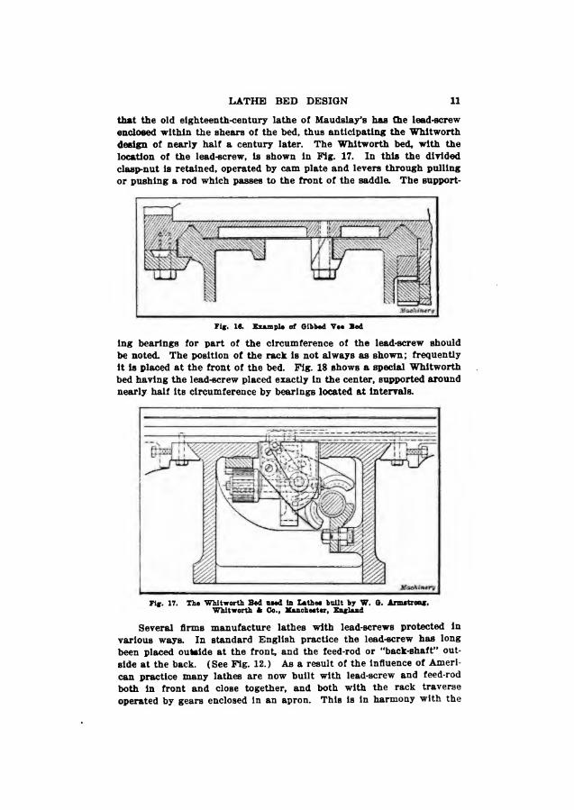
that the old eighteenth-century lathe of Maudslay’s has the lead-screw enclosed within the shears of the bed, thus anticipating the Whitworth design of nearly half a century later. The Whitworth bed, with the location of the lead-screw, is shown in Fig. 17. In this the divided clasp-nut is retained, operated by cam plate and levers through pulling or pushing a rod which passes to the front of the saddle. The support-
Vwfuntrg
Pig. 16. Example of Gibbod Vee Bed
ing bearings for part of the circumference of the lead-screw should be noted. The position of the rack is not always as shown; frequently it is placed at the front of the bed. Fig. 18 shows a special Whitworth bed having the lead-screw placed exactly in the center, supported around nearly half its circumference by bearings located at intervals.
Fif. 17. The Whitworth Bed used la Lathee built by W. G. Armstrong, Whitworth A Co., Manchester, England
Several firms manufacture lathes with lead-screws protected in various ways. In standard English practice the lead-screw has long been placed outside at the front, and the feed-rod or “back-shaft” out¬ side at the back. (See Fig. 12.) As a result of the influence of Ameri¬ can practice many lathes are now built with lead-screw and feed-rod both in front and close together, and both with the rack traverse operated by gears enclosed in an apron. This is in harmony with the
12 No. Ill—LATHE BED DESIGN
Idea of obtaining the motion required for screw cutting and feed from a gear box on the bed in front of the headstock; it also permits a more compact arrangement of the carriage. It may be stated as a general rule that the best English makers now place the feed-rod in front in preference to placing it at the back, and there seems to be no doubt but that in a short time the old “back-shaft” will disappear.
Development of the Sellers Lathe Bed
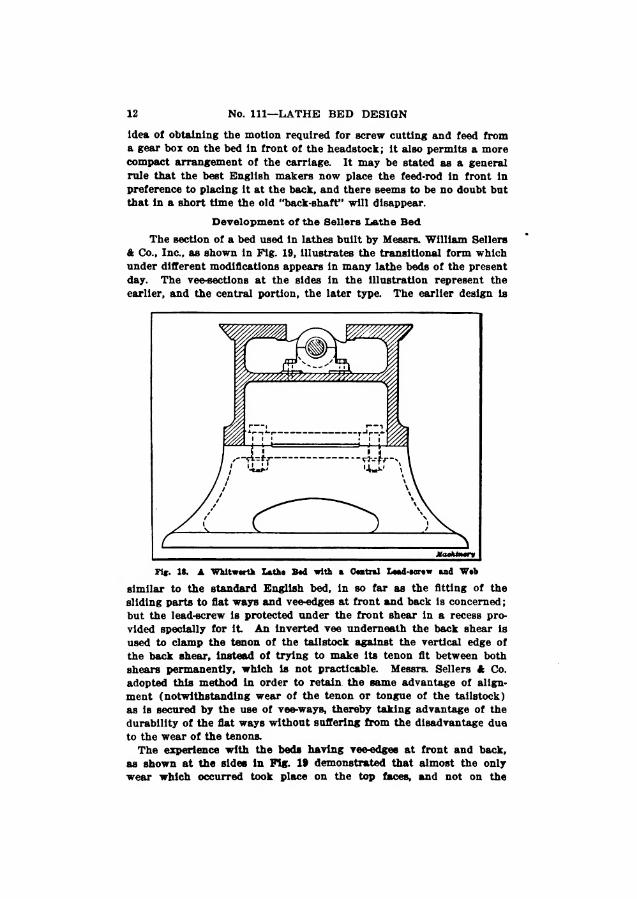
The section of a bed used in lathes built by Messrs. William Sellers ft Co., Inc., as shown in Fig. 19, illustrates the transitional form which under different modifications appears in many lathe beds of the present day. The vee-sections at the sides in the illustration represent the earlier, and the central portion, the later type. The earlier design is
Fig. 18. A Whitworth Lathe Bed with a Central Lead-screw and Web
similar to the standard English bed, in so far as the fitting of the sliding parts to flat ways and vee-edges at front and back is concerned; but the lead-screw is protected under the front shear in a recess pro¬ vided specially for it An inverted vee underneath the back shear is used to clamp the tenon of the tail stock against the vertical edge of the back shear, instead of trying to make its tenon fit between both shears permanently, which is not practicable. Messrs. Sellers ft Co. adopted this method in order to retain the same advantage of align¬ ment (notwithstanding wear of the tenon or tongue of the tailstock) as is secured by the use of vee-ways, thereby taking advantage of the durability of the flat ways without suffering from the disadvantage due to the wear of the tenons.
The experience with the beds having vee-edges at front and back, as shown at the sides in Fig. 19 demonstrated that almost the only wear which occurred took place on the top faces, and not on the
LATHE BED DESIGN 13
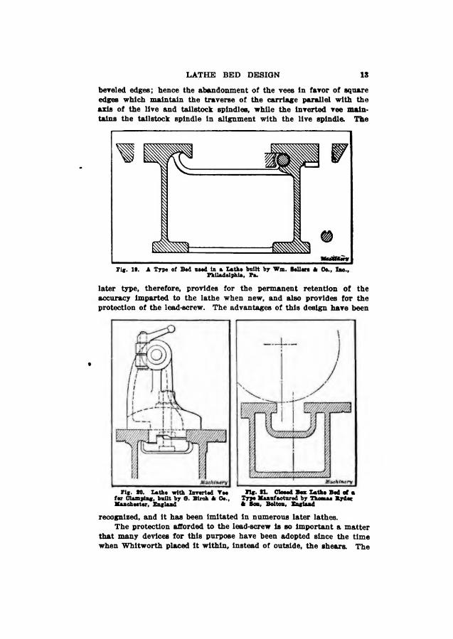
beveled edges; hence the abandonment of the vees in favor of square edges which maintain the traverse of the carriage parallel with the axis of the live and tailstock spindles, while the Inverted vee main- tains the tailstock spindle In alignment with the live spindle. The
Fig. 19. A Type of Bod uood in a Latha built by Wm. Boilers A Oo., Imo., Philadelphia, Pa.
later type, therefore, provides for the permanent retention of the accuracy Imparted to the lathe when new, and also provides for the protection of the lead-screw. The advantages of this design have been
Fig. to. Lathe with Inverted Vee Kg. SL Closed Boa Laths Bed of a for Clamping, built by O. Biroh A 0e., Type Manufactured by Thomas Ryder Manoheeter, England A Boa, Bolton, England
recognized, and It has been Imitated In numerous later lathes. The protection afforded to the lead-screw is so Important a matter
that many devices for this purpose have been adopted since the time when Whitworth placed It within. Instead of outside, the shears. The
14 No. Ill—LATHE BED DESIGN
Sellers* design embodies a decided improvement, for in it the lead-screw is supported along its entire length by the recess which is provided for it, and, therefore, it cannot be deflected. But the half-nut is single* and only extends around a rather small arc of the circle. These Sellers* beds also were among the first American designs which em¬ bodied the use of cross-ribs.
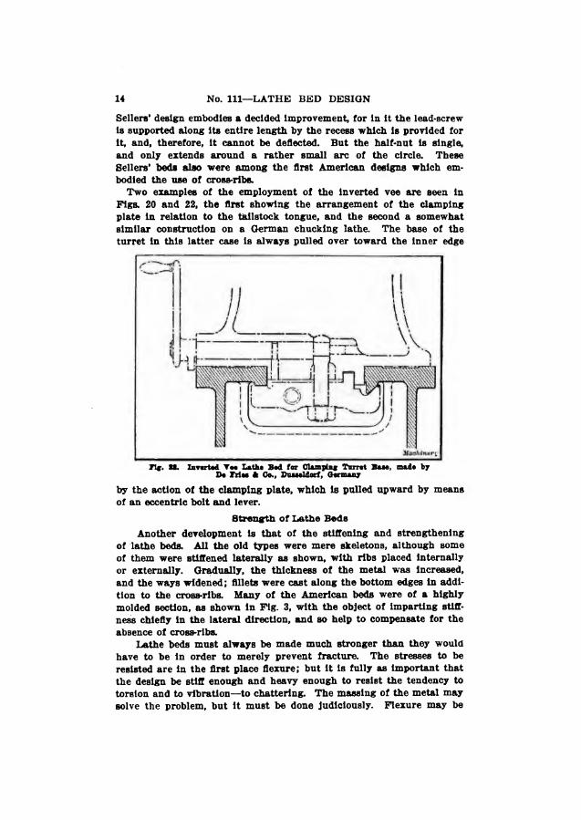
Two examples of the employment of the Inverted vee are seen in Pigs. 20 and 22, the first showing the arrangement of the clamping plate in relation to the tailstock tongue, and the second a somewhat similar construction on a German chucking lathe. The base of the turret in this latter case is always pulled over toward the inner edge
n*. 8*. Inverted Vee Lathe Bed for Clamping Turret Baee, made by Be Fries a Go., Bueeeldorf, Germany
by the action of the clamping plate, which is pulled upward by means of an eccentric bolt and lever.
Strength of Lathe Beds
Another development is that of the stiffening and strengthening of lathe beds. All the old types were mere skeletons, although some of them were stiffened laterally as shown, with ribs placed internally or externally. Gradually, the thickness of the metal was Increased, and the ways widened; fillets were cast along the bottom edges in addi¬ tion to the cross-ribs. Many of the American beds were of a highly molded section, as shown in Fig. 3, with the object of imparting stiff¬ ness chiefly in the lateral direction, and so help to compensate for the absence of cross-ribs.
Lathe beds must always be made much stronger than they would have to be in order to merely prevent fracture. The stresses to be resisted are in the first place flexure; but it is fully as important that the design be stiff enough and heavy enough to resist the tendency to torsion and to vibration—to chattering. The massing of the metal may solve the problem, but it must be done judiciously. Flexure may be

LATHE BED DESIGN 15
met by Increasing the depth, because the strength increases as the square of the depth. Torsion is more difficult to prevent, while resist¬ ance to vibration demands a mass of metal obtained only by consider¬ ably increasing the dimensions which are required to prevent flexure and torsion. Experiments have been undertaken at various times from which certain broad deductions have been made; but lathe beds are, notwithstanding, mainly evolved from previous practical experience. Although the general movement has been going on for a century, this evolution has been especially noteworthy since the advent of high¬ speed steel.
The flexure of a lathe bed is more than allowed for by the propor¬ tions given to it for general strength. A very light bed might possibly be bent by the placing of a very heavy piece of work between the
centers, or by the stress of heavy cutting near the center of the bed. In some American beds the standards or legs have been set a certain distance inward from the ends in order to shorten the length of the unsupported portion. Sometimes the beds are cambered or fish-bellied; long beds have legs in addition to those at the ends; or in heavy lathes, the bed is continuous and rests on foundations located at intervals. An unsupported length which will not bend, provided the bed is of box section, is given by Mr. Richards as one which is not more than twelve times its depth.
An interesting example of the gradual increase in bed dimensions for one size of lathe is shown in Fig. 23. This engraving illustrates the evolution of the lathe bed of Messrs. John Lang A Sons, of John¬ stone, Scotland. The ordinary English type is seen in dotted outline; this type was employed by the firm previous to 1900. The thin full lines show the first narrow guide type of bed of 1900, and the thick full lines the present type.

16 No. Ill—LATHE BED DESIGN
Torsion can be best avoided, as far as the shape of the bed is con¬ cerned, by making it of a box section. Comparatively few lathe beds are, however, constructed in that manner, the general design being that of two shears connected by cross-bars or ribs, thus leaving the top and bottom edges unconnected. That this is a poor design is admitted, but it is one which is more easily molded than a box shape. Long ago Prof. Sweet had some castings made for a test, as indicated in Fig. 24. These castings represent, respectively, the open-frame and the box
type of beds, with the same amount of metal in each. The box casting proved much stlffer laterally, and thirteen times more rigid against torsion.
9 m B i i i i i I H i
IP™ ■■Pi
f!». U, The Bioharda Box Bod
Several firms now construct beds which are wholly or partially boxed. It is, of course, necessary to leave some provision in the form of openings for the escape of chips and oil. Messrs. George Richards ft Co., Ltd., of Manchester, England, though they have now given up the manufacture of ordinary lathes, were in the field when this depart¬ ure was made. Their first lathe beds were made as shown in Fig. 25. The beds were practically encased along the top, and well tied to the

LATHE BED DESIGN 17
cross-ribs along the bottom with broad flanges. Holes cast in the top casing permitted the chips to fall through. The holes were surrounded by a rib to prevent loss of strength due to the cutting of the holes. Otherwise in its general design, the bed is of ordinary English type, with flat ways, vee-edges, and a gap.
In Fig. 21 is shown a section of the beds of the lathes manufactured by Messrs. Thos. Ryder 4b Son, of Bolton, England. These beds are of solid box section. In this design the practice of bringing the lathe centers considerably behind the center of the bed is adopted, in order to afford additional support to the cutting tool when turning large diam¬ eters. The depth of the rear guide strip of the bed is also deepened to increase its durability.
Dr. Nicolson has stated that if the same amount of metal put into
the ordinary beds were put into the box-shaped or the circular form, these types would be from six to ten times as strong to resist twisting. This is not so high an estimate as that given many years ago by Prof. Sweet, but it is amply high enough to justify that departure from the old practice which several lathe makers now have adopted. The solid box form is practicable, and easily manufactured; but the circular form is not, except in light lathes, such as those used by watch- and dock- makers, amateurs, and scientific workers. For such purposes, several examples of this type are built The circular bed must have a longi¬ tudinal guide or guides for the headstock and slide-rest or carrb and it is here that the difficulty arises in massive designs. In ftp heavy designs, the circular bed may be dismissed as nearly imp ble, or at least undesirable, in face of the fact that boxed be* tangular section can be and are constructed better and mi and of equal strength.

18 No. Ill—LATHE BED DESIGN
The circular bed is cheaply made for small lathes of, say, from 6- to 10-inch swing. It is used for these, not bo much because it happens to be the stiffest form, but because of the advantage which it offers for swivelling the rest to different angles, thus making it a kind of uni¬ versal tool for all kinds of cutting. This design is adopted in the recent lathes of that type built by Messrs. Drummond Brothers, Ltd., of Guild¬ ford, England. The bed, of cast iron, 3 inches in diameter, is of hollow form, ground on the outside to a limit of 0.0001 inch, and on it the heads and saddle fit As seen in Fig. 26, there is a slot in the under side of the bed which receives a tongue or bush secured to the bolt that passes up to transmit the motion from the lead-screw. By tightening
the nut on this bolt the swivelling portion A is locked. The range of swivel is indicated by the radiating center lines. Fig. 27 shows the complete tool-rest, with the upper part held in the split socket of the saddle, thus permitting of a horizontal swivel movement which enables the tool, or the top of the rest, to be moved in a universal manner.
This lathe, in its swivel action, resembles the Pittler lathe, although the latter is designed in a different way. In the Pittler lathe, the longi¬ tudinal guidance is provided for by a section of trapezoidal shape, with¬ in which the lead-screw passes. The form of this bed is plainly indi¬ cated in Fig. 28. The swivel motion is provided for by making the outside of the sliding carriage circular, and fitting the saddle of the slide-rest to it In this way the sliding movement is com¬ bined with a circular movement through a complete circle. The stem of the tool-rest can be swiveled in the socket in the split saddle. The

remarkable revolution in lathe construction—the application ot the principle ot the narrow snide. This principle, although so lately taken up In earnest. Is not by any means new. To determine the period of its first application would seem impossible, but illustrations showing the idea applied to lathe carriages appeared some twenty-five years ago. The three illustrations Figs. 30, 31 and 32, are taken from Joshua Rose’s “Modern Machine Shop Practice,” and show how the principle was applied many years ago. All three of these illustrations are re sen ted in recent practice, and it is noteworthy how the const* has been brought into prominence chiefly by the development speed lathes. Messrs. John Lang ft Sons, when they re-dee

20 No. Ill—LATHE BED DESIGN

LATHE BED DESIGN 21
on the front shear, or by an under hanging strip, without affecting the principle Sometimes the strip is raised above the general level of the bed surfaces, and sometimes it is formed by m*iHng a recess or channel in the front shear, although this is open to the objection that such a recess easily collects and stores the chips. The upstanding ledge, again, is more liable to become damaged.
Pig. 34 illustrates the Lang bed with its saddle. It is possible with this design to obtain a length of guide of as much as ten times the
riff. St. The E. X. LoBload Mtohiai Tool Co.’s Desiffm of Lathe Bod
width between the guiding surfaces, which has the effect of producing a very steady movement, with a much greater amount of freedom from twisting than is the case when the saddle fits on the f
outer edges of the shears. The setting-up of the tai can have no possible tendency to spring the sides as it might possibly have in the ordinary type cJ
In conjunction with the narrow guide, it bring the lead-screw as close as is practicab
22 No. Ill—LATHE BED DESIGN
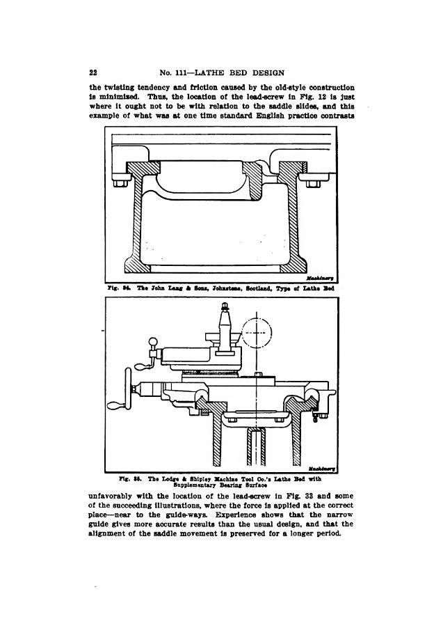
the twisting tendency and friction caused by the old-style construction is minimised. Thus, the location of the lead-screw in Fig. 12 is just where it ought not to be with relation to the saddle slides, and this example of what was at one time standard English practice contrasts
of the succeeding illustrations, where the force is applied at the correct place—near to the guide-ways. Experience shows that the narrow guide gives more accurate results than the usual design, and that the alignment of the saddle movement is preserved for a longer period.
23 LATHE BED DESIGN
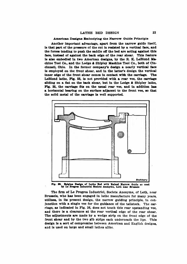
American Designs Embodying the Narrow Guide Principle
Another important advantage, apart from the narrow guide itself, is that part of the pressure of the cut is resisted by a vertical face, and the forces tending to push the saddle off the bed are acting against this face, instead of against the back edge of the rear shear. This feature is also embodied in two American designs, by the R. K. LeBlond Ma¬ chine Tool Col, and the Lodge A Shipley Machine Tool Co., both of Cin¬ cinnati, Ohio. In the former company's design a nearly vertical face is employed on the front shear, and in the latter’s design the vertical inner edge of the front shear comes in contact with the carriage. The LeBlond lathe. Fig. 33, is not provided with a rear vee, the carriage sliding on a flat on the back shear, but in the Lodge A Shipley lathe. Fig. 35, the carriage fits on the usual rear vee, and in addition has a horizontal bearing on the surface adjacent to the front vee, so that the solid metal of the carriage is well supported.
The firm of Le Progres Industrie^ Societe Anonyme, of Loth, near Brussels, who has been engaged in lathe manufacture for many years, utilizes, in its present design, the narrow guiding principle, in con¬ junction with a single vee for the guidance of the tailstock. The car¬ riage, as indicated in Fig. 36, does not touch this rear upstanding vee, and there is a clearance at the rear vertical edge of the rear shear. The adjustments are made by a wedge strip on the front edge of the front shear and by the two gib strips each underneath the lips. This design is a sort of compromise between American and English designs, and is used on large and small lathes alike.

24 No. Ill—LATHE BED DESIGN

LATHE BED DESIGN

26 No. Ill—LATHE BED DESIGN
s* flifis
hill
or 1 3 ” n !ip
*0 rCl M
H

LATHE BED DESIGN 27
way. In design the proportion of length to width of the narrow guide is about 4 to 1, but, as mentioned previously, in some cases where a strip is employed, the proportion may be as high as 10 to 1. Some firms who retain the front shear for guidance, as in the example Just referred to, lengthen the wings of the saddle to the right and left In order to increase the bearing length. The tailstock slides be¬ tween these wings up to the main body of the saddle.
Another design of a new 20-inch high-speed lathe, made by Messrs. Smith A Coventry, Ltd., of Manchester, England, is shown in Figs. 41
and 42. The two views here given illustrate the method of fitting the saddle and the tailstock. The front shear constitutes the narrow guide, with its take-up strip on the front face. The horizontal bearing is amply provided for by three ways; on the two at the rear the tailstock slides, as shown by Fig. 41. Gib strips are located under the front and rear edges.
Messrs. Ward, Haggas A Smith, of Keighley, England, fit their lathes with a narrow guide of the type shown in Fig. 43. This design is of the inverted type, the take-up strip drawing the saddle against the inside sloping face of the hanging lip of the front shear. These sur¬ faces are thus out of the way of the chips, and a great proportion of length to width of bearing surface is secured. The lead-screw and rack are brought very close to the guiding area. Fig. 44 Illustrates the method of tightening the tailstock by a clamping plate which presses against a sloping face on the inside of the rear way, thus draw-


LATHE BED DESIGN 29
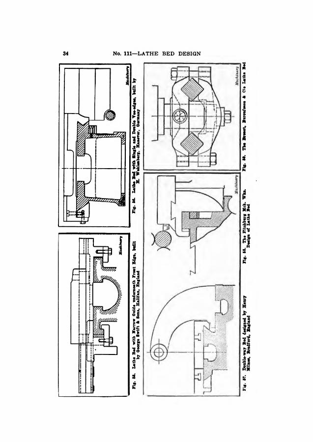
ing the tailstock against the back vertical edge of the shear. As this edge is not subjected to wear from the saddle, which clears it, the alignment is preserved indefinitely. Another example of an under- hanging lip employed as a guide is that of the high-speed lathes built by Messrs. George Swift ft Sons, of Halifax, England, as shown in Fig. 55, which shows the saddle without its apron.
In certain types of lathes one shear is employed alone to guide and support the carriage. This design is met with in a certain type of boring and turning lathe, where two duplicate carriages are run each on its own way, and are entirely fhdependent of each other. A
lower slideway or tier takes the overhang of the carriages. In another instance, that of the Libby turret lathe, made by the International Machine Tool Co., Indianapolis, Ind., the carriage fits over the front shear, as shown in Fig. 45, and a lower vee-guide opposes the tilting tendency of the carriage.
The principle of affording support to the carriage at some point situated below the general level of the bed surfaces is met with in several designs. One of the most successful examples is that of Messrs. Darling ft Sellers, Ltd., of Keighley, England. A bed section of one of their lathes is shown in Fig. 48. The auxiliary or “lower-tier" bed is made in the form of a strong lip, projecting out from the front of the bed near the bottom. The saddle has a bearing on this, as well as on the top surfaces of the bed. The overhanging weight of the saddle is thus supported in a very satisfactory manner, and it will be seen that the actual effective width of the bed is increased

3

LATHE BED DESIGN 31
ledge, which helps to resist the forces tending to separate the gears and rack and pinion, while under heavy duty. With a similar object in view, some makers support the rack-pinion by the metal of the saddle, in order (see Fig. 5) to prevent the springing away of the pinion. Another device is to alter the position of the rack and pinion to a vertical location, and support the pinion shaft In bearings on both sides of the pinion. A design of this kind is shown in Fig. 50, showing the construction in a lathe made by Messrs. Joshua Buck- ton & Co., Ltd., Leeds, England.
A different kind of lower-tier bed is made by Messrs. Drummond Brothers, Ltd., of Guildford, England. This bed is employed for their
lathes having 15- and 18-lnch swing. The gap is permanently open, and the saddle is guided by two lower tiers or slide-rails, so that it can be brought along on these past the gap and close up to the largest faceplate, with a minimum of tool overhang.
Another example of a lower-tier bed is that used in a lathe built by Schaerer & Co., of Karlsruhe, Germany, in which the advantages previously mentioned regarding the support of the carriage below the top level of the bed are obtained. There are two lower-tier vee-ways, as shown in Fig. 62, set at different heights (by which it is claimed that twisting is eliminated), and directly underneath the regular ways, so that chips cannot fall into them. The top of the bed is arranged with a vee and a flat to carry the headstock. The carriage has no bearing on the top, but only in the vee-ways. The position of the lead-screw and rack should be noted.

32 No. Ill—LATHE BED DESIGN
Methods for Protecting- the Ways of Lathe Beds from Chip
A few instances are met with in which lathe beds are modified specifically for the purpose of protection. The bed is either cast of such a form that the slides come below the top surface, as in the example just noted, or extra covering plates or guards are fitted to keep the chips away from the bearing surfaces. A bed made by the London firm George Richards, Ltd., Fig. 51, has a top portion A which serves as a cover over the slides, and at the same time guides the saddle at the front, forming a narrow guide between its inner face and the outer front edge of the main bed. The surfaces B, on which the carriage slides are, therefore, absolutely protected from chips, and
Flff. 61. ▲ German Type of Lathe Bod with Guard Plates ever the Slides
the lubricant does not become dirty. At the top of the portion A the saddle clears this casting.
Fig. 63 shows a German bed section which has the slideways ar¬ ranged a little below the top surface. Steel covering plates, screwed on as guards, prevent chips from falling onto the ways. The tail- stock slides on the top part of the bed, between the inner edges of the covering plates.
Messrs. John Lang & Sons build a range of surfacing and boring lathes (chucking lathes) without tailstocks, in which curved cast-iron guards, supported on short studs at each end, extend from the tail-end of the bed up to the chuck, so that chips cannot fall upon the flat ways of the bed, but are deflected by the guards and thrown off to one side. The section of a bed with its saddle cored to pass the guards, is shown in Fig. 64. It will be noticed that the saddle bears against the vertical edges of the front shear only, giving a narrow guide-way with a relation of length to width of about 7 to 1. The cross-slide (not shown) also fits on the same principle, being gibbed to the two edges of one slideway.

LATHE BED DESIGN 33
A rather carious type of bed is shown in Fig. 56. This type re¬ sembles an English bed at the back shear, bat has a doable "vertical” yee at the front edge. This lathe is made by H. Wohlenberg, of Hanover, Germany.
Double-way Type of Lathe Bede
Among the lathe beds which are made to bat a limited extent are those of the double-way type, that is, beds with separate ways for the carriage and the tailstock. They are useful for work where it is required to move the carriage rapidly ont of the way, and bring the tailstock up to the head without having to remove the carriage each time. The illustration Fig. 67 shows an example of this class, con¬ structed by Henry Mllnes, of Bradford, England. The tailstock slides on a back shear, below the carriage ways.
A special type of double-way bed. Fig. 60, the speciality of Messrs. Dron & Lawson, Ltd., of Glasgow, Scotland, comprises a flat-topped way carrying the tailstock, the tongue of which has a tapered adjust¬ ing strip to maintain the lit In the groove, and a loose bed A, resting on two extensions B which project from the main bed. The auxiliary bed A can be swivelled on the extensions for taper turning, and can be adjusted to and from the centers. The slide-rest is carried on bed A, and is fitted by a narrow guide at the front The slide-rest can be moved past the tailstock, and the center of the latter need not over¬ hang. Motion is conveyd to the screw of the slide-rest for feeding, through a universal-joint shaft from the gear box in front of the head- stock. Graduations indicate the amount of taper when the bed is swivelled. A similar principle is employed in the Niles lathes for turning printing-press cylinders, paper-machine rolls, etc., there being
sequent freed* vibration. By carrying the webs up between the two bes f”tg. 73, the two bearings axe ftnx&i \keA
34 No. Ill—LATHE BED DESIGN
LATHE BED DESIGN 3S
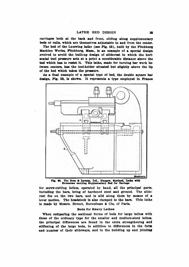
carriages both at the back and front, sliding along supplementary beds or rails, which are themselves adjustable to and from the center.
The bed of the Lo-swing lathe (see Fig. 68), built by the Fitchburg Machine Works, Fitchburg, Mass., is an example of a special design evolved to avoid the built-up design of slide-rest in which the hori¬ zontal tool pressure acts at a point a considerable distance above the bed which has to resist it This lathe, made for turning bar work be¬ tween centers, has the tool-holder situated but slightly above the lip of the bed which takes the pressure.
As a final example of a special type of bed, the double square bar design. Fig. 69, is shown. It represents a type employed in France
for screw-cutting lathes, operated by hand, all the principal parts. Including the bars, being of hardened steel and ground. The slide- rest fits on the two bars, and is slid along them by means of a lever motion. The headstock is also clamped to the bars. This lathe is made by Messrs. Brenot, Buronfosse & Cie, of Paris.
Beds for Heavy Lathes
When comparing the sectional forms of beds for large lathes with those of the ordinary type for the smaller and medium-sized lathes, the principal differences are found in the extra strengthening and stiffening of the large beds, in addition to differences in the fora and number of their slideways, and in the building up and jointing

No. Ill—LATHE BED DESIGN 36
of the sections, which for manufacturing reasons sometimes take the place of a single large casting. Extra ribbing or webbing is one of the first changes introduced as the sixes of beds increase, as shown in Fig. 46, where webs are carried down on the inside from the top, and in Fig. 47, where the inner ribs completely duplicate the outer webs. Many variations of this type exist, which it is impossible to illustrate here. It may be mentioned that the bed in Fig. 46 is from a large lathe by Messrs. Hulse k Co., Ltd., of Manchester, England, provided with the firm’s non-rotating twin lead-screws. There is one screw on each side of the bed, as shown, so that the saddle is propelled in a perfectly even manner, without risk of twisting.
The number of ways is increased to three, four, and even more, in large beds, according to the design of saddles employed, and their number. Three ways, as shown in Fig. 61, are frequently employed
when there are independent front and rear saddles, which fit on the front and back ways, respectively, and rest partly on the central one so that they may pass each other. The edges may be square or of vee form as indicated in the illustration. Beds with four slide-ways for two or more independent saddles are often used in place of the type in Fig. 61, in the larger lathes. The fitting of saddles and rests for turning large diameters on faceplate work introduces the use of wing or sole-plates, extending from the side of the main bed, or in some cases cast with it and provided with a slide-way. For certain functions, as in wheel lathes, a long cross-bed passes across in front of the face¬ plate, and Is bolted to wings extending from the sides of the main bed. In any case, for turning large diameters, it is necessary to make the effective width of the bed sufficient to bring the tool-rests out to the required radius.
In some types of lathes for facing only, there Is no bed at all, but only a stand to carry the headstock, and a T-slotted plate in front of this, which has no slide-ways, but which simply supports the tool- rest

CHAPTER II
THE LONQITUDINAIj FORMS OF LATHS BEDS
The remarks made In the previous chapter relative to the flexure and torsion of lathe beds need not be repeated here* but we shall consider, with the aid of the representative illustrations, how flexure is best resisted, and how the longitudinal shapes are modified to serve different functions. The principal differences which are made in the forms of beds are those arising from variations in dimensions, while subsidiary differences are produced by special deidgna of lathes or additional functions or by the particular class of work which is done in the lathe Thus the shapes of beds of similar dimensions for ordinary screw-catting or engine lathes and those for turret lathes are very often radically different In the one case provision has to be included for the screw-cutting and feeding devices for the carriage motions and for the tailstock, while in many turret lathes these features are absent, and the bed is plainer, with provision only for clamping the turret base and the cross-slide. On the other hand, the arrangements for lubricating the cutting tools and work often intro¬ duce complications into the design of turret lathe beds and the casting Is of a more elaborate character below the bed proper—around the top of the legs or standards
The length of a bed has an important influence upon its construction and the number of supporting points and if a gap is included, this also modifies the form to a considerable degree. The number of sup¬ ports ranges from the single cabinet standard in some small lathes and the two standards or legs in those of ordinary dimensions, to the three or more supports in longer beds A continuous bed of full depth for the whole length is employed in lathes for heavy work and large swing, and is supported solidly on concrete foundations The truth and rigidity of a lathe bed depends to a certain extent upon how it is fastened down. Ordinarily, beds are bolted rigidly to their foundation, which may be a wooden floor or a stone or concrete base.
Many years ago Pro! Sweet suggested the adoption of a tripod support for lathe beds, and this suggestion has been acted upon In practice. One end of the lathe is bolted down by the usual means, and the other is pivoted on a pin which passes through lugs in the bed and in the leg. The only support at that end is the pin on which the leg is free to adjust itself. Many firms also adopt the three-point support principle without any pivoting device: sometimes there are three points of contact with the foundation, and sometimes the bed is united to the legs at three points. The effect of an untrue foundation is thereby neutralised. Another method of affording good support is that of casting the bed with, or bolting it to, a single column of box form, which makes the lathe self-contained, and obviates

38 No. Ill—LATHE BED DESIGN
any risk of distortion or winding. This construction is employed both for small ordinary lathes, and for turret lathes up to fairly large dimensions.
Legs or Supports for Lathe Beds
When legs are used to support the bed, it is the custom of some makers to spread the legs under the head to a greater extent than those under the right-hand end, to resist the vibration, which is more pronounced at the headstock end. Other firms do not put ordinary ribbed legs at all under the headstock, but prefer a boxed cabinet support, even when there are legs at the other end. The principle of this seems faulty, since, if it is considered necessary to put a box support under the headstock end, the use of a flimsy support at the other end of a heavy bed appears unreasonable. Many makers view the matter in this light, and place the bed on equally solid and sub¬ stantial supports at both ends; sometimes the supports are of identical pattern, but frequently they are a little larger at the headstock end, in order to afford more cupboard room for tools and appliances.
The practice of placing the supports a certain distance inward from the ends, mentioned in the previous chapter, is followed in many Instances, and a further development of this principle is found in the case of some lathes, particularly those with gaps, where the metal of the boxed bed is carried down to a considerable depth under the head- stock, gradually tapering off towards the ends. A great many turret lathes have their supports placed some distance inward from the ends of the bed, and the under side of the latter is often tapered or curved upward from the outside of the legs to the ends of the bed.
Gap Lathes
The question of forming a gap in a lathe bed has long been the subject of controversy. A gap lathe bed is practically as common in England as a straight bed. Theoretical considerations have been urged against it, chiefly on the ground that the bed is weakened, because its continuity is broken; but an English lathe maker would argue that the metal which is removed can be more than compensated for by extra metal placed underneath and beyond the gap, and in the heavier lathes by metal brought down to the ground in the form of a broad foot The real objection to a gap is its unalterable dimensions—it is wider than is required for some jobs, and not wide enough for others. The fitting of the bridge-piece is also liable to become slightly inaccurate when a lathe has done much service, but this can be rectified. Thirty or forty years ago such lathes predominated over all others, but gradually, with the growth in specialization, they were displaced, to some extent, by straight-bed lathes on the one hand, and by regular facing lathes, and vertical turning and boring mills, on the other.
The movable gap is used to a moderate extent, in medium and large sizes of lathes, and would be adopted more extensively but for the fact of the ever-growing specialization. The breadth of gap is adjust-

40 No. Ill—LATHE BED DESIGN
able within a wide range, or it may be closed up entirely, the object being, of course, to support the carriage as close as practicable to the cutting point of the tool under all conditions. The most serious defect in gap lathes, perhaps, is the fact that the lead-screw has to be kept low down to be out of the way. In the movable-gap lathes an¬ other difficulty arises in the driving of the lead-screw, which has to be done from gears at the right-hand end of the bed.
Fig. 37 shows the form of a good type of bed, supported on box standards at both ends. The bed is equipped for the use of cutting lubricant or oil, though not in such a perfect manner as some beds shown later. A more elaborate type of bed for a 20-inch high-speed lathe, built by Smith k Coventry, Ltd., of Manchester, England, is
Jiff. 64. Bed for Saudi Lethe
shown in Fig. 65. The cross-sectional shape of this bed is shown in the previous chapter. The details of the boxing and cross-ribbing and the Joining of the bed to its standards will be observed. The right-hand standard is surrounded by an oil rim which conducts the lubricant into the trough, and at the top of the bed, close to the headstock, a space is left for the oil and chips to drop down into the trough.
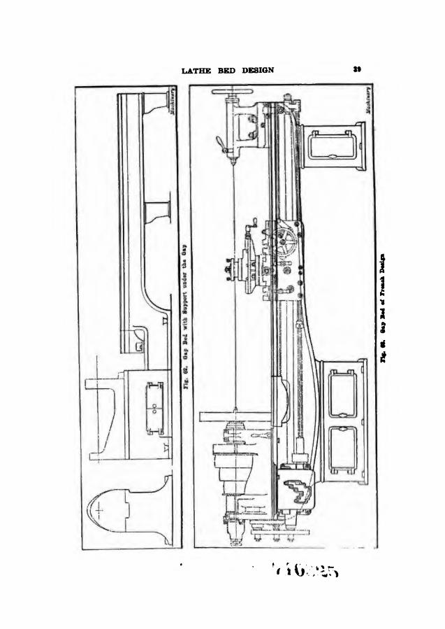
The two principal designs of gap lathes are represented in Figs. 38 and 62, the first having the gap compensated for by the usual deepen¬ ing underneath, and the other having a continuous base, such as is adopted for heavier lathes. In each case an intermediate leg is located under the bed, owing to its length. It will be noticed that in one case the gap-piece entirely fills the opening, while in the other it only partially does so, leaving a space for a large face-plate or chuck to remain in place, and still providing sufficient length for the support of the saddle.
Fig. 63 shows a French design of gap bed in which the metal is carried down in a graceful curve under the gap. The bed is well

LATHE 41

42 No. Ill—LATHE BED DESIGN
is o
f th
e box t
yp
e, w
ith a
mp
le s
up
po
rt u
nder
nea
th t
he h
ead-
Th
e ar
rangem
ents fo
r lu
bri
cati
on
of
the
cutt
ing
tool
and

LATHE BED DESIGN 43
Bed fo
r S
mal
l L
ath
e w
ith H
ead and
Oil F
as
oaa
t S
elid w
ith It

>. Ill—LATHE BED DESIGN

46 No. Ill—LATHE BED DESIGN
wit
h
all-
gea
red
hea
ds,
the w
ebbin
g
exte
ndin
g np
fro
m th
e
to
rece
ive
big
cone
pu
lley
s o
r gea
rs,
whic
h
could
not
be
bed
to
form
th
e lo
wer h
alf
of
the gea
r g
uar
ds.
Th
ere
is
done
if th
e hea
d
wer
e m
ade
sep
arat
ely
.
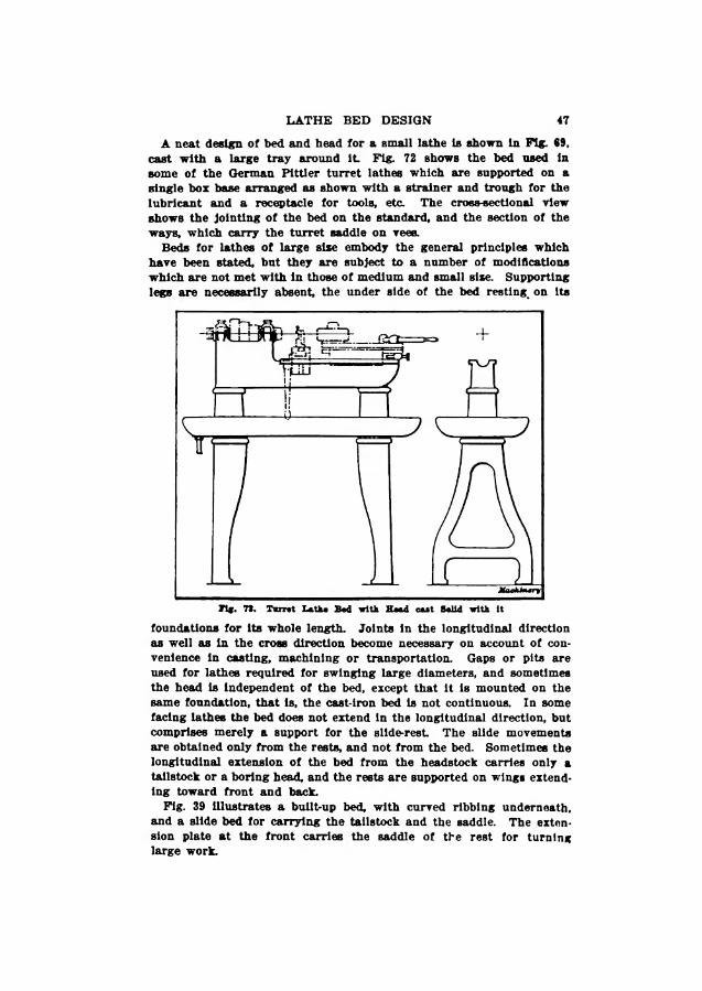
LATHE BED DESIGN 47
A neat design of bed and head for a small lathe is shown in Tig. €9, cast with a large tray around it Fig. 72 shows the bed used in some of the German Pittler turret lathes which are supported on a single box base arranged as shown with a strainer and trough for the lubricant and a receptacle for tools, etc. The cross-sectional view shows the jointing of the bed on the standard, and the section of the ways, which carry the turret saddle on vees.
Beds for lathes of large size embody the general principles which hare been stated, but they are subject to a number of modifications which are not met with in those of medium and small size. Supporting legs are necessarily absent, the under side of the bed resting, on its
foundations for its whole length. Joints in the longitudinal direction as well as in the cross direction become necessary on account of con¬ venience in casting, machining or transportation. Gaps or pits are used for lathes required for swinging large diameters, and sometimes the head is independent of the bed, except that it is mounted on the same foundation, that is, the cast-iron bed is not continuous. In some facing lathes the bed does not extend in the longitudinal direction, but comprises merely a support for the slide-rest The slide movements are obtained only from the rests, and not from the bed. Sometimes the longitudinal extension of the bed from the headstock carries only a tailstock or a boring head, and the rests are supported on wings extend¬ ing toward front and back.
Fig. 39 illustrates a buildup bed, with curved ribbing underneath, and a slide bed for carrying the tailstock and the saddle. The exten¬ sion plate at the front carries the saddle of the rest for turning large work.

Machinery is the leading journal in the machine-build¬
ing field and meets the requirements of the me¬ chanical engineer* super¬ intendent, designer, tool¬ maker and machinist, as no other journal does* Machinery is a monthly and deals with machine design* tool design* ma¬ chine construction, shop practice, shop systems and shop management The reading matter in Machinery is written by practical men and edited by mechanical men of long practical training. The twelve numbers a year contain a thousand
pages of carefully selected and edited mechanical information. Each number of Machinery contains a variety of articles on
machine shop practice. These articles include carefully prepared descriptions of manufacturing methods and current mechanical developments. Shop systems and shop management are ably handled by the foremost writers. Every number contains the most extensive and complete monthly record published by any journal, or in any form, of new machinery and tools and acces¬ sories for the machine shop. A special department is devoted to **Letters on Practical Subjects/1 to which practical mechanics contribute their experiences. There is a department of Shop Kinks—brief, concise little contributions which contain ideas of value to the man in the shop or at the drafting table.
The mechanical engineer, machine designer and draftsman are also well provided for in Machinery. Every number con tains articles on the theory and practice of machine design, on the properties of materials, and on labor-saving methods and systems. There are reviews of research work in the mechanical field, valuable results of carefully made experiments are recorded* and the world's progress in every field of mechanical endeavor is closely watched.
One of the most valuable features is the four-page monthly Data Sheet Supplement printed on strong m anil a paper. These Data Sheets contain high-grade, condensed mechanical data* covering machine design, machine operation and kindred subjects. They are the cream of mechanical information.

No* 41, Drop Forging.—t#ag rml of Plant: IlHb (vl* of Drop Forging; Die*.
No, *6. Hardening and Tempering.—tug Flant*; Treating lllgb Wpred HfeH riardmlng Gage*.
No. IT. Electric Oterhead CrawM,—Drrlgn ami CVnUttlatkui.
No, 46. File* and Filing—Type* nf HI#-*; l oins and UaMi'g riles-
No* 49, Girder* for Electric Overhead Cr*am,
No. 40. Ftiaoipki and Pra^Uo* of IhubVIIbi Machine Tool*, Part I-
Na. 61 Principle* and Practice of AiacmbUng Machine Toot*, Fart It.
No, 62. Advanced Shop Arithmetic for the Mneblakt.
No, U. Uw of Logarithm* and Logarithmic Tablet.
No. M. Salu lion of Trfanfkt* 1‘ifl 1 — Mrltmrt*. I;nlt« *1*4 lUantplet,
No. 66 Solution of trtuflH. Pirt tt — Titbit* **f Vaturel Fmulkeia,
No. 61, Natl l«H»N.-“l,tlucl|il*» of MM»*i i an*i rut Uim*
No. 67, Hotel Spinning,—Machine*, Tool* and U tl.J.lll 1 '*• it*
No. 61 RoLSrol nod Elliptic Springe.—(kind*. h>m and [w*igu.
Mo, 69, Machlnee, Took and Method* of Into, mobile Manufacturer
No* m, Cone traction end Manufacture of Aula- mobile*.
No, 61. Bleckemith Shop Practice.— M«ki IMtiletmlfli Shopi Welding; Forging of liwh* end riieina, MkcWUainwu*.
No, Gf, KerdnoM end DitnWiUj Testing of Medal!*
No, AS, Meet Traetmcnt of Steel.—Birilfning, Two fW,rb> s. Caeo-flard riling.
No. 64* G*t* Kmhiag and Lapping.
No. 96. Form u lee and Com teat a fur Gal Eogine Oentgau
No, 61* Heating end Ventilation of Shop! and Offices.
No* 67* Boiler*.
No* 66. Boiler Furnace* and Chinmejr*.
No* m* Feed Water Appliance*,
No, TO, Steam Sofia «*-
No, 71. Steam Turbine**
No. 7f. Pump*, Condwteori* Steam end Water Piping*
No, TS* Principle* and Application* of Eire- irltity.—Static ItortrHtfi ffleclrlcal Me-**u re*
|t*uurin.
Xo, 74 Principle* and Application of Eke Uldlfi-Kapi^iMl Nlr. lro Mapm U*uj, Werlrti IQ* tin*’
No, 76* Principle* and Application* of Eko- trtaltg,—DpHnoi; Motor*; Clectflr llaliwiij*.
No. 71. Msdlslte and Application* of Elec trieitj. Fieriirk Lighting.
No, 77* Priaetpk* and Applicationl of Eke- iri.Jlp. ami Telephone
No. 74. Piiliclpk* and Application* ul Kl#i Ulelty — Tratt*mlealon of |Vo*r.
No. 79, tocotnaiito Building,—M* tot and Side It ode.
No. €0. Locometire BulliUof*—VTliiwIai A*W; Dti* lug ItOlrW,
Me. 61* t&comotir* Building, —t'jrllndv** and Ffeim**-
No, 62. Locomotive Building*—V a We Motion*
No. 66, Locomotive Building,—Bolter SWp t*fairiler.
Mo, 64, Locomotive BuHdlng.—Erecting,
Me, AS, Mechanical Drawing. — In elm men I*; MetcrWle; Geometrical ProUkuu.
No. tt, Mechanical Drawing,— Projection,
No, 67, Mechanical Drawing,—Machine Detail*.
No. 66. Mechanical Drawing,—Machine Defalk
No, St, The Theory of Shrinkage and Forced Pita.
Na, 90. Railway Repair Simp Practice.
No. 61. Operation of Machine Took*—Tim I a the. Fart 1
No. It. Operation of Machine Toole. 1 hr Fetlm. l>rl II
Mo, 96. Oprfoiloe of M*r,!»loe Tool*. - PlM«t. KliApfr, Xltdler.
No. 64. Opiratlon of Machine Tool*, —Drilling MecUlaau,
No, 65. Operation of Machine Took.—Boring MncMnoe*
No, #B, Operation o«f Machine Took,—Milling MocMuea, Fart I.
No, 67. Operation of Machine Took,—Milling Me filing, Part IL
No, 66, Operation of Machine Toole,—-Grinding Marti 1m.
No. Automatic Screw Maobina Prat-tier.— tllmnltou of tbu Brown A Slurp* Automatic Screw MocUbie.
No, 100. AutomatiO Screw Machine Practice.— n^Mlgirlitg oml fulling Came for Tlu» Antuinalk Screw Machine,
No, 101. An tome tie Screw Machine Practice,— Clrt tiler Farming and Cut off Toole*
No. 106, Automatic Screw Machine Practice.— Nlftaruai Cutting Toola.
No. 106. Automatic Screw Machine Praotioe,— Internal Cut ting Took.
No, 104, Automatic Screw Machine Practice.— Thriiadlng Ojiera Ilona*
No. IPS Automatic Screw Machine Frmetioe,— KniixHug U jo.1 rati one.
No. 166, Automatic Screw Machine Practice,— Cross Drilling, Burring and Slotting Operntlaiia
No, 107. D^op Forging Die* and Die-Sfahlag.— A OtNUpkte Tree Hat? on Dle-ilnklng Method*,
No, 169. Die Casting Machined*
No, 10S. Die Canting,—:Method* and Machine* t i**d; the Making «*f Dice for Die Cimting,
No, 110, Th* Eatirueion of Mitila-Wirhlwe mid Mi'lbM* ITnH In a l.Ulle kmmn Field **t Metal WufWbg,
Na, 111. Lethe Bed Benign.
No. Ilf. Mavhloe Stupe, Tripe and Looking It* eioei,—Atm la elude* H*trfalng Meehan I line end Clamping Detier*
tfigmcKti Tmn wux iif. ahnouncm w m.cffnuAT ritiH tt. tv«s.

MACHINERY'S DATA SHEET SERIES
Machinery's Data Sheet Books include the well-known serlea of Data Sheet* originated by Macuixehy* and issued monthly as supplements to the publication, of these Data Sheets over 600 have been published* and 6,000,000 copies sold. Be- vised and greatly amplified, they are now presented In book form, kindred sub- jecta being grouped together. The price of each hook is 25 cents (one shilling)
1 delivered anywhere in the world
CONTENTS OF DATA SHEET BOOKS
Na l, Screw Thrciiii,--tTnlt«1 States. TYUlt- wimh* Sharp V- and BritHh A«*oMftiiou Thread*; ftfigg* Plpv Thread; Oil Well Caning Oifn; Fire lli-'1 t'uuuvciiun*Atmir. Wurui und Metric TbrvndB; Mmliluf, Wood, Lag Srrvw, und Cni*- iimifi: Bolt TbrvbfU, rt<*.
No. 2, Sciewa. Belli anti Wills,—Fillister lurnl, HrOdbim, Coltif In ari utut Hvxagmi livid S*tvw*; ^lumlurd ami Nut*; TmU», T'txrftK and Waatn*rn; n>QUb BCfiWIi and N u i*; Mach Luh< Screw Lifutij. \Vr>mi Scmn; Taj* PriUn,
No. 3, TAp* and Dies.—Hand, MacbUiv, Tapper nail Jluchlfti' HltvA T«|Tui-ivt U:- I r - Hubs: Strew Mmlnm Tups; Straight and Taper Itullvr Tape; Stay tmlt. Wauhtnii, nail Pairh, bolt
Pipe Tbjm hi id Hob* Tiihendlng tHra,
No, 4, Roomers, Backet*, DtUIi and Milling Cutters,—II.ind BctftlftrH; Sb*-H Rcium-r* and Ac born; I'lpii Kcitmvr*; Tupvr Pin* uih! Kraiimr*; Brown A Sharpe* Mo mo nud Janto TB|m* SovkH* and Rea ra era; Drill*; Win* Gngva; Milling Cotters; Setting Angle* fur Milling Teolta lit End MUIt 4j.11 tl Angular Cutters, elf.
No* S. Spar Getting*—GlurirKrart and Circular Pitch: DUai'iiataue of Mj>tir Gear*; Table* of Pttvh PlaHMtttff*: (Mnningritph TsMvaj Uniting Mill lu it , String tb of spur Gear*; Horuepowivr Trans* inittrd by Coat Iron and ituwtiide Plnhm*; De*lgu of Spur Gtsir*; EptiryclU! Grating.
No, e. Bev*I, Spiral and Worm Gearing, —Rule* and Formula* for Hot*1! Grata; Strength of Sb-wl (IvatB; Itadgn of Rcfet Gciira; Hub* and /Winulna fur Spiral Gear*: Diagram for Outturn for Spiral Goars; Ral»i and Formula* for Worm Gvarlug, etc.
No. 7. ShaTLlng, Keyi and Keywayi.—norao- powvr of Shafting; Strength of Shafting; Porting* Driving* Shrinking and llntming Pit*: VVtMwtnilI Key*: Sinmturd: Key*; Gib Key*; Milling Key- way as DapltX Key**
No, S. Bearings* Coupling*' Clutch** „ Craae drain and Hooka.—Pillow Bluett*; Babbitted Belt Inga* Boll «iid Roller Hearings; Clamp Couplings; Flange Coupttnga; Tooth (Satclinc; Criih cVmplinjf*; i'AAm dutches; rnlifi*r*al JolM*; Cram- Chllm; (Vane Hooks; Drum Score*.
No* B, Sprinirs, Slide* and Machine Details,— Furnuilah and Tables for Spring Cflb ulutlotis Ma¬ chine Slide*; Machine Handle* and LeVrhi: Collar*; Baud Wheel*: Pina and Cettem; Tilrii-bucUea.
No* 10, Motor HtWc* Speeds ami Feedi, Change Gearing, and Boring Bar*,^—Power minim! for Machine Tool*: Cutting Speeds mid P*artja for Cartu>n *nd HljfliJtpefd Steel; Screw Mu eh Inc Spvedi and Peed*: Heat Treatment of Htab wpi'etl Steel Tool*; Tapvr Turning; t’houije Gearing for tile T*thr; Boring Bara and Tool*,
Ni>, It, Milling Xa chip a In do ling. Clamping Dv vices and Plan nr Jack**—Table* for MUllng Ala- thlm* Deleting; rbangi^ Gcura for Milling Splral« Angle* for eel ting Iioletlug Head when Milling llutcliva; Jig natutdug Betlcea,
No* 12. Pipe and! Pipe Tltlingi.—Pipe Tbrraja and Pu*t iron Plitbiga* Bronco Flltinga; 1*14*0 t'bi uif e- „ Ptpv Bends* B1|k Clamp* and Hanger*.
No* 13. Baiters and Chlmneya,—■ plue Spacing mo) HfriivUig ti>r Boilers, Htrengtli of Bollwr Jui^ti; lUrellng; Boiler Selling: i Lilmurja,
Wo. II, TocoEnotlve and Hallwny DaU*— Lock siiti11 * * Hattara; Eirnrlng Proaabrws fur ljun»tnot)T* Journals, Loeoinnflvt* ClaBBlbcntUxia; ttiili Sectiona; CrotTi, Swllrbe* and t'nmw^irvn; Mire*; Trtrdm I Foive; Inertia of Trulii*; Brake lanehs.
No. Ifi. Steam and Go* Emdsn***—^ft*twrat*,| SI emit; Sleum IHpe tftavM: sfenifi Kugiuv In-mgn* Volume of Cylln^b rh; sruinog Bogta: Hettlxig Cor- 11 h» Kiiglno VuBe Geiira; CoddOdtOr and Air Vtinip Jblta; llorHepower of Gauotbie Kogtru**; Aut+>ioo bile ling die CrunkahufU* etc.
No* 13. Mathematical Tahiti* — Srpj&rr* of UUvd N’umtirrn; rnnetloti^ of Practtoua; CIpcuiii- fvrenee and BbiiJieterH r>f t'lrelea; 'fablva for Wjt*ae* hig off Clrelvn; Solution af TrlungUai Forninta* for Solving Regular Polygon*; QiOnWflal Pro gren*lonf ett*
Nn, 17. Kechanioi atnl Strength of Matoriala*— Work, Energy; CfnlrtfugHl Pofev; tVnier of Gras ify* Motion; Krlrtlnn; IVndnliJin ; Fulling BudW; Stmigtli of MatoyliH*: Strength of Plat Plat***; Strength, of Thick Cylinder*, etc.
No. IS* Bears Formulas and Structural Design, Benin Formula*, Seetintio] Moduli of SlrurBrrwl
ShiijM.'*; Benin Charts. Net Aren* of Strtn tbral Afiglra: UliM’t Sputlng; SpMci« for Fhacincla and I benma; Stre*eea In Iiuuf Truaaea, etc.
No. 10.—Bolt, Rope alii Chain DrlTo*,—^Dlmet> elouH nf I'uHeyw; Wetgbte of Pulley*’, !k>r*vpot*er of Belting; Belt Velocity; Aeyulnr Bell HrWea: ncirm?4)ower tmiivintiled by Hope*; Sliestm for Hope Drive: Striwea In wife KOj Bpmckcti fnr link Cbatmi; For uni In n nml Tabtita for Driving Chain*
No, 20. Wiring DUrrams, Heating and VantUa- lion, ami Miacelbkneoua Tables. Typical Motor Wiring Diagram*; B^ifttOTni' of Bound tVfppr W1f4L; t’urrent Bt*r»Jtl*’« for V*nrltnih Cuntaetx and M.itii'biD:; Oeotrlfugnl Fun and Blower OapaeD tic*; Mol Water Main dipnoittat; lipelniift) r.^itlvn* leHtn, Metric CanWH*b>tl Table*. Weight# nnd Spin-lfle Gmivity of Mels!*. Drafting room Voaw Tvntluna etc.
MArnticBBT, the leading journal In the machine-building field, the originator of the 25-cent Reference and Data Books, Published monthly, Subscription, $2*0i) yearly. Foreign subscription, 13,00.
The Induetrial Pretis* Publishers of Machinery,
49-55 Lateyett© Street, New York City* tJ. 8. A*