
Lathe Accessories
63
1 Lathe Accessories Session 7
-
Upload
kabir-khan -
Category
Documents
-
view
52 -
download
6
Transcript of Lathe Accessories

1
Lathe Accessories
Session 7

2
Lathe Accessories
• Divided into two categories• Work-holding, -supporting, and –driving
devices• Lathe centers, chucks, faceplates• Mandrels, steady and follower rests• Lathe dogs, drive plates
• Cutting-tool-holding devices• Straight and offset toolholders• Threading toolholders, boring bars• Turret-type toolposts

3
Lathe Centers
• Work to be turned between centers must have center hole drilled in each end
• Provides bearing surface
• Support during cutting
• Most common have solid Morse taper shank60º centers, steel with carbide tips
• Care to adjust and lubricate occasionally

4
Lathe Centers

5
Revolving Tailstock Centers• Replaced solid dead centers for most
machining operations• Used to support work held in chuck or
when work is being machined between centers
• Contains antifriction bearings which allow center to revolve with workpiece
• No lubrication required between center and work
• Types: revolving dead center, long point center, and changeable point center

6
Revolving Tailstock Centers

7
Microset Adjustable Center• Fits into tailstock spindle
• Provides means of aligning lathe centers or producing slight tapers on work machined between centers
• Eccentric slide (dovetail) allows center to be adjusted limited amount to each side of center

8
Microset Adjustable Center
9
Self-Driving Live Center
• Mounted in headstock spindle• Used when entire length of workpiece is being
machined in one operation• Chuck or lathe dog could not be used to drive work
• Grooves ground around circumference of lathe center point provide drive
• Work usually soft material such as aluminum

10
Self-Driving Live Center

11
Chucks
• Used extensively for holding work for lathe machining operations
• Work large or unusual shape
• Most commonly used lathe chucks• Three-jaw universal• Four-jaw independent• Collet chuck

12
Three-jaw Universal Chuck
• Holds round and hexagonal work• Grasps work quickly and accurate
within few thousandths/inch• Three jaws move simultaneously when
adjusted by chuck wrench• Caused by scroll plate into which all three
jaws fit
• Two sets of jaw: outside chucking and inside chucking

13
Three-jaw Universal Chuck
14
Four-Jaw Independent Chuck• Used to hold round, square,
hexagonal, and irregularly shaped workpieces
• Has four jaws• Each can be adjusted independently by
chuck wrench
• Jaws can be reversed to hold work by inside diameter

15
Four-Jaw Independent Chucks

16
Headstock Spindle Types1. Threaded spindle nose
• Screws on in a clockwise direction
2. Tapered spindle nose• Held by lock nut that tightens on chuck
3. Cam-lock spindle nose• Held by tightening cam-locks using T-
wrench• Chuck aligned by taper on spindle nose

17
Threaded Spindle Nose

18
Tapered Spindle Nose

19
Cam Lock Spindle Nose

20
Collet Chucks
• Most accurate chuck• Used for high-precision work• Spring collets available to hold round,
square, or hexagon-shaped workpieces• Each collet has range of only few
thousandths of an inch over or under size stamped on collet
21
Spring Collet Chucks
• Spring-collet chuck• One form: Handwheel draws collet into
tapered adapter• Another form: Uses chuck wrench to
tighten collet on workpiece• Can hold larger work than draw-in type

22
Spring Collet Chucks
|

23
Spring Collet Chucks

24
Jacobs Collet Chuck
• Jacobs collet chuck• Utilizes impact-tightening handwheel to
close collets• Wider range than spring-collet chuck

25
Jacobs Collet Chuck

26
Magnetic Chucks
• Used to hold iron or steel parts that are too thin or may be damaged if held in conventional chuck
• Fitted to an adapter mounted on headstock spindle
• Used only for light cuts and for special grinding applications

27
Magnetic Chucks

28
Faceplates
• Used to hold work too large or shaped so it cannot be held in chuck or between centers
• Usually equipped with several slots to permit use of bolts to secure work
• Angle plate used so axis of workpiece may be aligned with lathe centers
• Counterbalance fastened to faceplate when work mounted off center
• Prevent imbalance and resultant vibrations

29
Faceplates

30
Faceplates

31
Steadyrest• Used to support long work held in chuck
or between lathe centers• Prevent springing
• Located on and aligned by ways of the lathe
• Positioned at any point along lathe bed
• Three jaws tipped with plastic, bronze or rollers may be adjusted to support any work diameter with steadyrest capacity

32
Steadyrest

33
Follower Rest
• Mounted on saddle
• Travels with carriage to prevent work from springing up and away from cutting tool
• Cutting tool generally positioned just ahead of follower rest
• Provide smooth bearing surface for two jaws of follower rest

34
Follower Rest

35
Mandrel
• Holds internally machined workpiece between centers so further machining operations are concentric with bore
• Several types, but most common• Plain mandrel• Expanding mandrel• Gang mandrel• Stub mandrel

36
Plain Mandrel

37
Expanding Mandrel

38
Gang Mandrel

39
Stub Mandrel

40
Lathe Dogs
• Drives work machined between centers
• Has opening to receive work and setscrew to fasten the dog to work
• Tail of dog fits into slot on driveplate and provides drive to workpiece
• Made in variety of sizes and types to suit various workpieces

41
Standard bent-tail lathe dog• Most commonly used for
round workpieces• Available with square-head
setscrews of headless setscrews

42
Standard bent-tail lathe dog• Bent tail engages in slot on
drive plate

43
Straight-tail lathe dog
• Driven by stud in driveplate• Used in precision turning

44
Safety clamp lathe dog
• Used to hold variety of work
• Wide range of adjustment

45
Heavy Duty Lathe Dog
• Wider range than others
• Used on all shapes

46
Cutting-Tool-Holding Devices• Available in three styles
• Left-hand offset• Right-hand offset• Straight
• Each has square hole to accommodate square toolbit held in place by setscrew
• Angle of approximately 15º to 30º to base of toolholder

47
Left-Hand Offset Toolholder• Offset to the right
• Designed for machining work close to chuck or faceplate and cutting right to left
• Designated by letter L

48
Right-Hand Offset Toolholder
• Offset to the left• Designed for machining work close to the
tailstock and cutting left to right• Also for facing operations
• Designated by letter R

49
Straight Toolholder
• General-purpose type
• Used for taking cuts in either direction and for general machining operations
• Designated by letter S
50
Carbide Toolholder
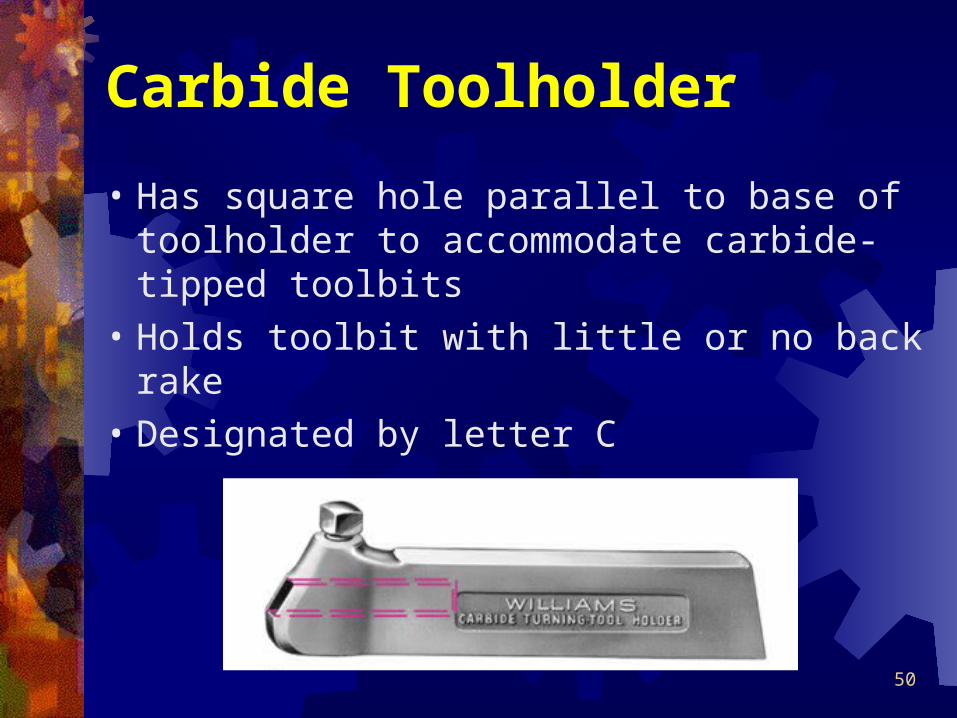
• Has square hole parallel to base of toolholder to accommodate carbide-tipped toolbits
• Holds toolbit with little or no back rake
• Designated by letter C

51
Cutting-Off (Parting) Tools• Used when work must be grooved or
parted off• Long, thin cutting-off blade locked
securely in toolholder by either cam lock or locking nut
• Three types of parting toolholders• Left-hand• Right-hand• Straight

52
Threading Toolholder
• Designed to hold special form-relieved thread-cutting tool
• Has accurately ground 60º angle• Maintained throughout life of tool• Only top of cutting surface sharpened
when becomes dull

53
Styles of Boring Toolholders• Held in standard toolpost
• Light boring toolholder• Used for small holes and light cuts
• Medium boring toolholder• Suitable for heavier cuts• May be held at 45º or 90º to axis of bar
• Mounted on compound rest of lathe• Heavy-duty boring bar holder
• Three bars of different diameters• May be held at 45º or 90º to axis of bar

54
Compound Rest Tooling Systems• Standard, or round, toolpost
• Generally supplied with conventional engine lathe
• Fits into T-slot of compound rest• Provides means of holding and adjusting
type of toolholder or cutting tool required• Concave ring and the wedge or rocker
provide for adjustment of cutting-tool height

55
Conventional ToolPosts

56
Modular (Quick-Change) Tooling• Initially developed for CNC machine
tools to improve accuracy, reduce tool-change time and increase productivity
• Benefits realized on conventional lathes with systems designed for these machines
• Modular tooling system must be rigid, accurate and have quick-change capabilities
• Basic clamping unit or turret can hold variety of cutting tool modules

57
Modular (Quick-Change) Tooling• Initially developed for CNC machine
tools to improve accuracy, reduce tool-change time and increase productivity
• Benefits realized on conventional lathes with systems designed for these machines
• Modular tooling system must be rigid, accurate and have quick-change capabilities
• Basic clamping unit or turret can hold variety of cutting tool modules

58
Modular Tooling System• Principal function is to reduce cost of
keeping large tool inventory• Tools can be specifically mounted to suit
characteristics of workpiece• More common systems available
• The Super Quick-Change Toolpost• The Quadra* Index Toolpost• The Super-Six Index Turret• The Vertical Index Turret

59
Super Quick-Change Toolpost• Provides fast, accurate, and reliable
method of quickly changing and setting various toolholders for different operations
• Locking system has two sliding gibs forced out against toolholder
• Handle pulled into lock position• Provides rigid, positive lock with zero
backlash

60
Super Quick-Change Toolpost

61
Quadr* Index Toolpost
• Allows four tools to be mounted on turret at same time
• Each tool locked independently• Provides flexibility to use from one to four
tools simultaneously
• Unique indexing system of turret allows it to be set in 24 positions (every 15º)

62
Super-Six Index Turret
• Designed to simplify and increase machining productivity on engine lathes when multi-operation jobs require use of more than one tool
• Up to six tools for external and internal machining operations
• Allows height adjustment for each tool
• Tool changes can be made in less than 1 sec

63
Vertical Index Turret (VIT)• Designed to give highest accuracy,
fastest tool change and greatest rigidity of any tool system available for engine lathes
• Same concept as indexing turrets on CNC lathes
• Can hold up to six or eight tools• Closest to performance of CNC lathes


