
Latest News Petts Hill Underbridge Reconstruction · 2014-07-09 · Balfour Beatty Birse Rail hands...
12
Transcript of Latest News Petts Hill Underbridge Reconstruction · 2014-07-09 · Balfour Beatty Birse Rail hands...
Latest News
Birse Rail completes 'Access
for All' improvements at
Slough Station
May is Sustainability Month at
Balfour Beatty
Birse Rail hands back ‘Access
For All’ scheme at
Sittingbourne Station
Birse Rail awarded £16m
contract on the Birmingham
Gateway project
Birse Rail awarded two
Building and Civils Delivery
Partnership Contracts
News Archive >>
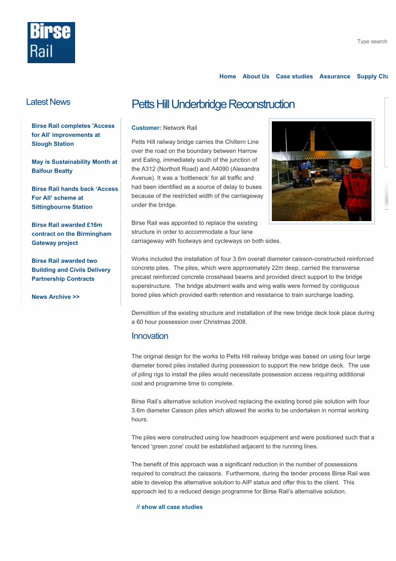
Petts Hill Underbridge Reconstruction
Customer: Network Rail
Petts Hill railway bridge carries the Chiltern Line
over the road on the boundary between Harrow
and Ealing, immediately south of the junction of
the A312 (Northolt Road) and A4090 (Alexandra
Avenue). It was a ‘bottleneck’ for all traffic and
had been identified as a source of delay to buses
because of the restricted width of the carriageway
under the bridge.
Birse Rail was appointed to replace the existing
structure in order to accommodate a four lane
carriageway with footways and cycleways on both sides.
Works included the installation of four 3.6m overall diameter caisson-constructed reinforced
concrete piles. The piles, which were approximately 22m deep, carried the transverse
precast reinforced concrete crosshead beams and provided direct support to the bridge
superstructure. The bridge abutment walls and wing walls were formed by contiguous
bored piles which provided earth retention and resistance to train surcharge loading.
Demolition of the existing structure and installation of the new bridge deck took place during
a 60 hour possession over Christmas 2008.
Innovation
The original design for the works to Petts Hill railway bridge was based on using four large
diameter bored piles installed during possession to support the new bridge deck. The use
of piling rigs to install the piles would necessitate possession access requiring additional
cost and programme time to complete.
Birse Rail’s alternative solution involved replacing the existing bored pile solution with four
3.6m diameter Caisson piles which allowed the works to be undertaken in normal working
hours.
The piles were constructed using low headroom equipment and were positioned such that a
fenced 'green zone' could be established adjacent to the running lines.
The benefit of this approach was a significant reduction in the number of possessions
required to construct the caissons. Furthermore, during the tender process Birse Rail was
able to develop the alternative solution to AIP status and offer this to the client. This
approach led to a reduced design programme for Birse Rail’s alternative solution.
// show all case studies
Type search here...
Home About Us Case studies Assurance Supply Chain

Birse Rail Limited is a company registered in England & Wales (company number 4319685)
with its registered office at 86 Station Road, Redhill, Surrey, RH1 1PQ.
A Company
About us
History
Our People
Awards
Innovation
Assurance
Health and Safety
Quality
Environment
Sustainability
Supply Chain
Case
Copyright © 2010 Birse Rail Ltd
Website by Fat Media
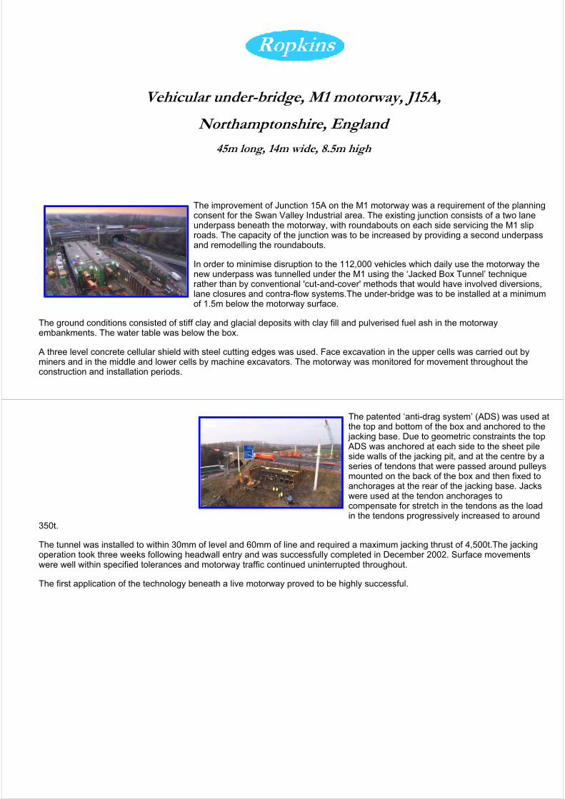
Vehicular under-bridge, M1 motorway, J15A,
Northamptonshire, England
45m long, 14m wide, 8.5m high
The improvement of Junction 15A on the M1 motorway was a requirement of the planning consent for the Swan Valley Industrial area. The existing junction consists of a two lane underpass beneath the motorway, with roundabouts on each side servicing the M1 slip roads. The capacity of the junction was to be increased by providing a second underpass and remodelling the roundabouts.
In order to minimise disruption to the 112,000 vehicles which daily use the motorway the new underpass was tunnelled under the M1 using the ‘Jacked Box Tunnel’ technique rather than by conventional 'cut-and-cover' methods that would have involved diversions, lane closures and contra-flow systems.The under-bridge was to be installed at a minimum of 1.5m below the motorway surface.
The ground conditions consisted of stiff clay and glacial deposits with clay fill and pulverised fuel ash in the motorway embankments. The water table was below the box.
A three level concrete cellular shield with steel cutting edges was used. Face excavation in the upper cells was carried out by miners and in the middle and lower cells by machine excavators. The motorway was monitored for movement throughout the construction and installation periods.
The patented ‘anti-drag system’ (ADS) was used at the top and bottom of the box and anchored to the jacking base. Due to geometric constraints the top ADS was anchored at each side to the sheet pile side walls of the jacking pit, and at the centre by a series of tendons that were passed around pulleys mounted on the back of the box and then fixed to anchorages at the rear of the jacking base. Jacks were used at the tendon anchorages to compensate for stretch in the tendons as the load in the tendons progressively increased to around
350t.
The tunnel was installed to within 30mm of level and 60mm of line and required a maximum jacking thrust of 4,500t.The jacking operation took three weeks following headwall entry and was successfully completed in December 2002. Surface movements were well within specified tolerances and motorway traffic continued uninterrupted throughout.
The first application of the technology beneath a live motorway proved to be highly successful.
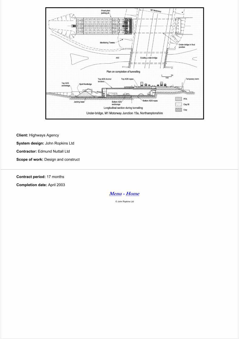
Client: Highways Agency
System design: John Ropkins Ltd
Contractor: Edmund Nuttall Ltd
Scope of work: Design and construct
Contract period: 17 months
Completion date: April 2003
Menu - Home
© John Ropkins Ltd
Prepared by John Sreeves Date 22/01/13
Checked by David Lear Date 11/02/13
Approved by David Lear Date 11/02/13
Halcrow Group Limited is a CH2M HILL company
Halcrow Group Limited Elms House, 43 Brook Green, London W6 7EF tel +44 20 3479 8000 fax +44 20 3479 8001 halcrow.com
Technical note
Project Bath Eastern Park and Ride Option Sites Date 22 January 2013
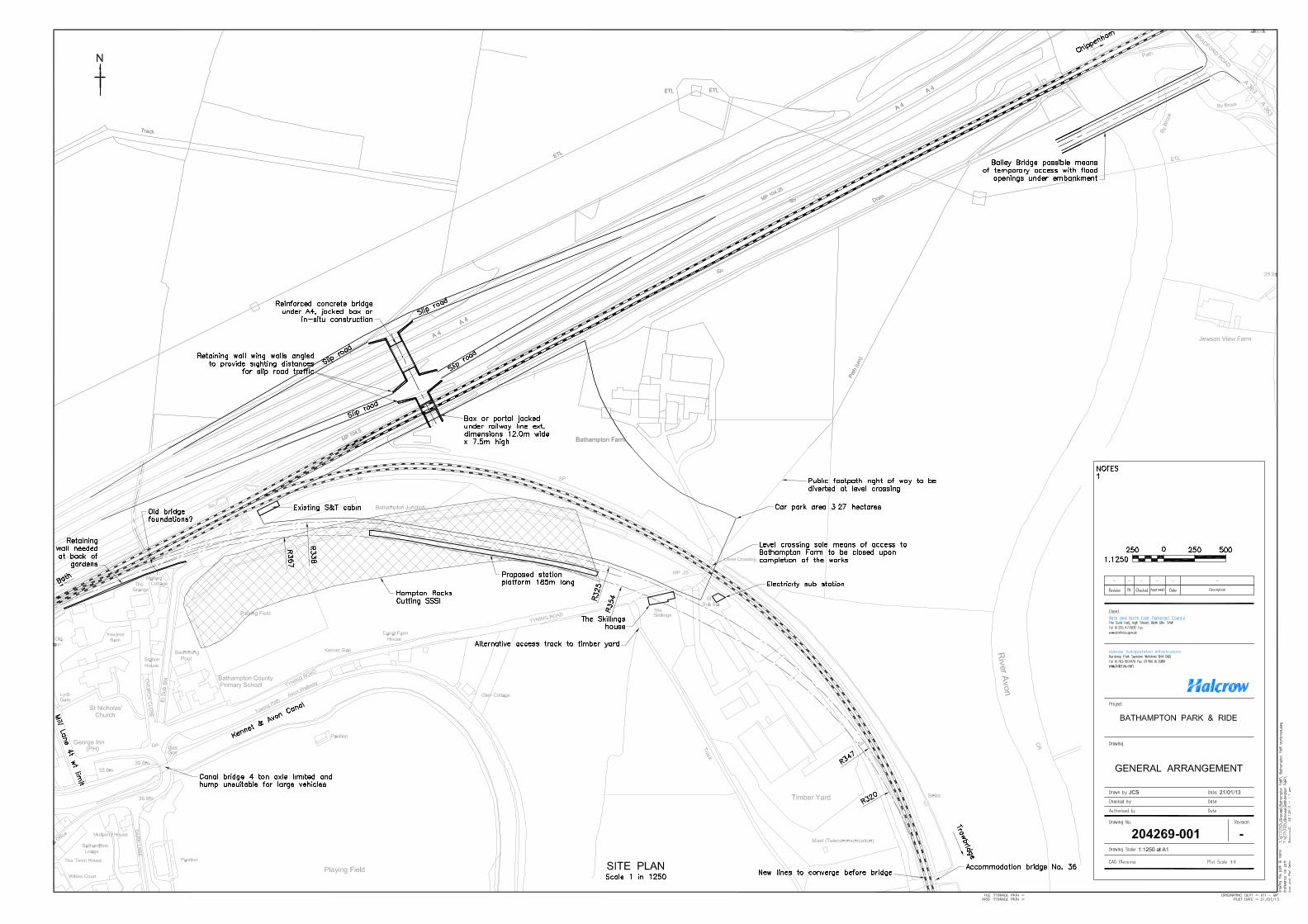
Subject Site H: Bathampton Junction - Bridge Works Ref 204269.AI.00.09/App C
Author John Sreeves
1 Introduction
In order to ease traffic congestion in Bath, a possible Park and Ride (P&R) scheme is proposed
at Bathampton junction. This P&R option would be rail based making use of train services that
currently serve the route to or from Trowbridge and Westbury. A new railway station with
parking facilities would be required; this station being alongside and east of the location of the
previous station that closed to passengers in 1966.
The following entries were extracted from The Bristol Railway Archive; http://bristol-
rail.co.uk/wiki/Bathampton_Station_and_Junction, and gives the history of the Bathampton
station site:
• Opened on 2nd February 1857;
• Closed to goods services on 10th June 1963 and passenger services on 3rd October 1966;
• Both Bathampton and Bathampton West signal boxes were replaced by a single box on 21st
September 1956; and
• There were sidings to a timber mill on the south side of the station which came into use on 10th
October 1922.
Bathampton forms a junction between the London to Bristol main line and the Trowbridge
line. Historical maps show that the original station had platforms flanking the main line west
of the junction divergence point, thus trains on both the mainline and the branch could serve
the station.
The A4 Batheaston bypass opened in 1996 and this runs parallel to and immediately north of
the London to Bristol railway line for a distance of 1.5km. Direct vehicular access from the
Technical note 22 January 2013 Page 2 of 7
Project: Bath Eastern Park and Ride Option Sites
Subject: Site H: Bathampton Junction - Bridge Works
P&R to the bypass is proposed. This Technical Note considers the engineering issues and
potential costs associated with bridging under the Great Western Main Line (GWML); and
also under the A4 to create a new ‘diamond’ interchange.
2 Bridge Engineering Works
2.1 Proposed Concept
Road access is envisaged from the A4 Batheaston bypass to the P&R via a grade separated
junction on the A4 and a bridge passing under the GWML. At this point, 375 metres east of
Mill Lane over bridge, the railway and the A4 road are approximately at the same level, and
the road is at the summit of a crest curve. This gives maximum headroom availability
underneath the road. On/off slip roads in both directions flanking the dual carriageway
descend at gradients of about 5%.
2.2 Construction Methodologies
The two bridges under the A4 and railway line need to provide a minimum internal width of
10.3m based upon two 3.65m lanes and 1.5m wide verges (TD 27/05). There will be a need for
wing-walls in the form of retaining walls at either end splayed back to satisfy sighting
distance criteria. The minimum headroom required is 5.3m to be provided over the full width
of the carriageway and verges, to which must be added an allowance for cross fall and
longitudinal drainage gradient. The thickness of the roof, walls and floor for a reinforced
concrete box would be about 0.85m resulting in external box dimensions in the order of 12.0m
wide and 7.5m high. On top of the box must be added 0.468m for track and 0.35m for ballast
and waterproofing, thus total construction depth would be a minimum of 1.668m from soffit
to rail level.
Possible forms of construction include:
• Jacked box advanced through the embankments under live traffic (example: M1 J15a).
Refer to Annex A;
• Jacked box constructed off line for positioning during an extended possession
(example: Owen St, Tipton, http://www.halcrow.com/Our-projects/Project-
details/Owen-Street-Relief-Road-England);
• Portal structure constructed off line and slid into place on guides pre-placed within
small tunnels within the base of the embankment; the slide taking place during an
extended possession (example: Chippenham A350 bypass http://www.hochtief-
construction.co.uk/bridges_holywell.shtml);
• Railway Bridge Only: A conventional half through steel bridge superstructure on
transversely spanning crossbeams supported by large diameter piles or caissons at
each corner. The piles are bored outside the railway clearance so do not interfere with
operations. The bridge is lifted in by crane during a short possession (example Petts
Hill http://www.birserail.co.uk/Case-Study/Petts-Hill-Underbridge-Reconstruction.
Refer to Annex B
• Road Bridge Only: in-situ concrete construction with traffic diverted along the slip
roads that would be constructed in advance.
Technical note 22 January 2013 Page 3 of 7
Project: Bath Eastern Park and Ride Option Sites
Subject: Site H: Bathampton Junction - Bridge Works
A major consideration is avoidance or minimisation of disruption to railway operations.
Possession planning often requires a three year lead in time and ‘extended possessions’ up to
four days or more are typically only available at Christmas and Easter. The box jack under the
M1 motorway at junction 15a was accomplished without any interruption of traffic; in this
case the top surface of the box was 1.5m below the highway running surface. Such an
approach would be preferred if acceptable to Network Rail albeit a temporary rail speed
restriction would be necessary for a period of about three weeks.
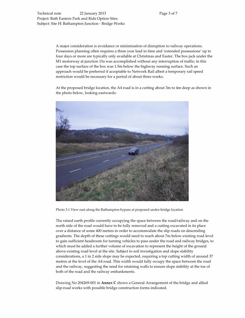
At the proposed bridge location, the A4 road is in a cutting about 3m to 4m deep as shown in
the photo below, looking eastwards:
Photo 3.1 View east along the Bathampton bypass at proposed under-bridge location
The raised earth profile currently occupying the space between the road/railway and on the
north side of the road would have to be fully removed and a cutting excavated in its place
over a distance of some 400 metres in order to accommodate the slip roads on descending
gradients. The depth of these cuttings would need to reach about 7m below existing road level
to gain sufficient headroom for turning vehicles to pass under the road and railway bridges, to
which must be added a further volume of excavation to represent the height of the ground
above existing road level at the site. Subject to soil investigation and slope stability
considerations, a 1 in 2 side slope may be expected, requiring a top cutting width of around 37
metres at the level of the A4 road. This width would fully occupy the space between the road
and the railway, suggesting the need for retaining walls to ensure slope stability at the toe of
both of the road and the railway embankments.
Drawing No 204269-001 in Annex C shows a General Arrangement of the bridge and allied
slip-road works with possible bridge construction forms indicated.
Technical note 22 January 2013 Page 4 of 7
Project: Bath Eastern Park and Ride Option Sites
Subject: Site H: Bathampton Junction - Bridge Works
2.3 Construction Access
The triangle of land proposed for the area of the P&R car park is land-locked with the railway
on two sides and the River Avon on the third side. The only means of access at present is via
the level crossing to Bathampton Farm, and this is at the end of the single track no-through
Tyning Road. The former accommodation bridge under the railway next to Bathampton Farm
was filled in when Batheaston Bypass was built.
The level crossing has user worked gates with miniature lights to indicate approach of trains.
The road approach to the level crossing from the west is on the inside of the railway curve
with reduced sighting distances of and from trains. Despite the use of gates and lights, use by
frequent construction traffic would increase the risk of a collision between road and rail
vehicles. Tyning Road itself passes a primary school and can only be reached via the toll
bridge to the north (4 ton weight limit) or a humped canal bridge to the south (4 ton axle limit
shown on a heritage sign). Both of these bridges are historic and Grade 2 listed.
Use of Tyning Road and the level crossing for large volumes of construction traffic and
materials would be impractical and unacceptable. Consequently all construction activities for
both P&R bridges under the A4 and railway would have to be carried out from the north of
the railway. Furthermore, since the space between the A4 and the railway would need to be
excavated for the junction slip roads, it follows that the construction compound can only be
north of the road.
Any off line construction of a new railway bridge (e.g. jacked box or portal) will need to be as
close as possible to its final position in order to be viable. Therefore such construction would
need to be immediately south of the railway; subject to access constraints discussed above
being overcome, or north of the railway in the narrow strip of land between the railway and
the road. For in-situ railway bridge construction similar to Petts Hill, the same proximity
requirements would apply for crane positioning.
To obtain sufficient working space and a site compound in the area between the railway and
the road; the area would need enlarging by temporarily narrowing the A4 dual carriageway to
single lanes in each direction and diverting to the north. The northern extremity of the road
diversion would ideally be maintained within the future highway footprint to minimise
encroachment onto the flood plain further north. Working space thus obtained would be
sufficient for construction for both the railway bridge the road bridge. Depending upon the
limitations of the available space that could be obtained by this method; construction of the
two bridges is likely to be consecutive as opposed to concurrent. As such; a construction
period of up to 18 months would be needed, during which the temporary traffic diversion
with speed restriction would need to be in force on the A4.
The option of having the site compound and working area wholly to the north of the A4 is
unlikely to be feasible since any off-line railway bridge construction would be more remote
from its final position. The temporary working area required would be likely to extend
beyond the future highway boundary into the flood plain to the north, with greater risk to the
project, environmental impact and the need for remediation measures.
Technical note 22 January 2013 Page 5 of 7
Project: Bath Eastern Park and Ride Option Sites
Subject: Site H: Bathampton Junction - Bridge Works
3 Other Structural Works and Issues
3.1 The Grange and Mallard Cottage
There will be a need for a retaining wall at the back of the gardens of The Grange and Mallard
Cottage to support the foot of the cutting which needs to be widened to accommodate the new
track alignment. There used to be an accommodation bridge crossing over the railway in this
area; probably demolished as part of the Batheaston bypass works. The presence of
foundations and old abutments should be expected in the area just north of The Grange, and
the need for removal of these obstructions should be expected. The likely extent of this
retaining structure is shown on Drawing 204269.001 (Annex C).
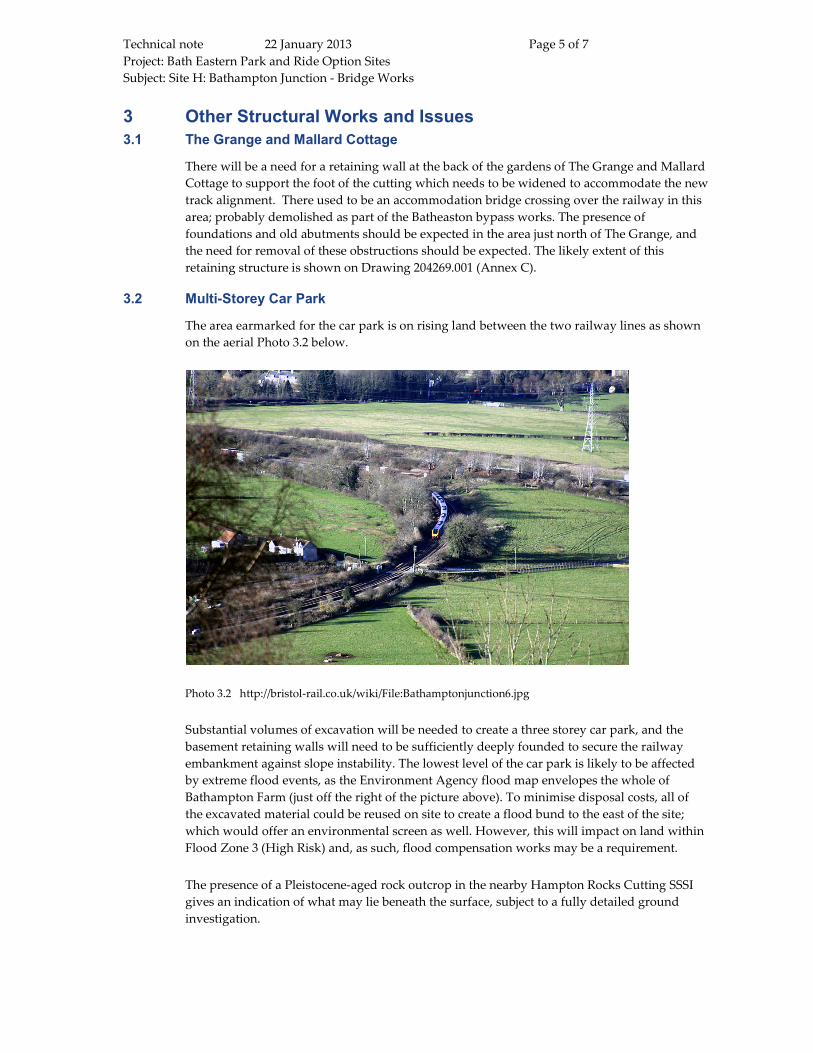
3.2 Multi-Storey Car Park
The area earmarked for the car park is on rising land between the two railway lines as shown
on the aerial Photo 3.2 below.
Photo 3.2 http://bristol-rail.co.uk/wiki/File:Bathamptonjunction6.jpg
Substantial volumes of excavation will be needed to create a three storey car park, and the
basement retaining walls will need to be sufficiently deeply founded to secure the railway
embankment against slope instability. The lowest level of the car park is likely to be affected
by extreme flood events, as the Environment Agency flood map envelopes the whole of
Bathampton Farm (just off the right of the picture above). To minimise disposal costs, all of
the excavated material could be reused on site to create a flood bund to the east of the site;
which would offer an environmental screen as well. However, this will impact on land within
Flood Zone 3 (High Risk) and, as such, flood compensation works may be a requirement.
The presence of a Pleistocene-aged rock outcrop in the nearby Hampton Rocks Cutting SSSI
gives an indication of what may lie beneath the surface, subject to a fully detailed ground
investigation.
Technical note 22 January 2013 Page 6 of 7
Project: Bath Eastern Park and Ride Option Sites
Subject: Site H: Bathampton Junction - Bridge Works
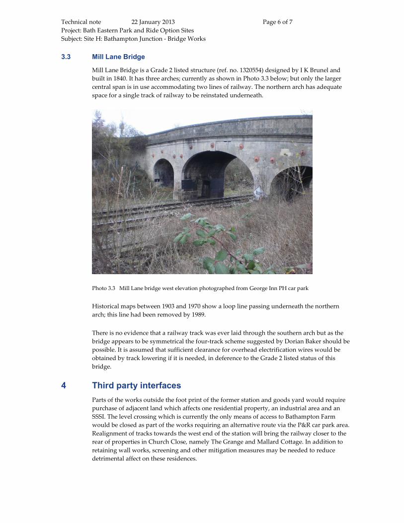
3.3 Mill Lane Bridge
Mill Lane Bridge is a Grade 2 listed structure (ref. no. 1320554) designed by I K Brunel and
built in 1840. It has three arches; currently as shown in Photo 3.3 below; but only the larger
central span is in use accommodating two lines of railway. The northern arch has adequate
space for a single track of railway to be reinstated underneath.
Photo 3.3 Mill Lane bridge west elevation photographed from George Inn PH car park
Historical maps between 1903 and 1970 show a loop line passing underneath the northern
arch; this line had been removed by 1989.
There is no evidence that a railway track was ever laid through the southern arch but as the
bridge appears to be symmetrical the four-track scheme suggested by Dorian Baker should be
possible. It is assumed that sufficient clearance for overhead electrification wires would be
obtained by track lowering if it is needed, in deference to the Grade 2 listed status of this
bridge.
4 Third party interfaces
Parts of the works outside the foot print of the former station and goods yard would require
purchase of adjacent land which affects one residential property, an industrial area and an
SSSI. The level crossing which is currently the only means of access to Bathampton Farm
would be closed as part of the works requiring an alternative route via the P&R car park area.
Realignment of tracks towards the west end of the station will bring the railway closer to the
rear of properties in Church Close, namely The Grange and Mallard Cottage. In addition to
retaining wall works, screening and other mitigation measures may be needed to reduce
detrimental affect on these residences.
Technical note 22 January 2013 Page 7 of 7
Project: Bath Eastern Park and Ride Option Sites
Subject: Site H: Bathampton Junction - Bridge Works
5 Procedures
In addition to planning consents granted by the local planning authority (B&NES), a
Transport & Works Act Order is likely to be needed prior to the construction and operation of
the new railway alignment and its station. A level crossing order will be required for stopping
up the level crossing that provides access to Bathampton Farm; and further orders will be
required for the diversion of the public footpath right of way that currently uses this route.
Other consents will be needed in relation to the SSSI and construction on or near the flood
plain.
Any objections will have to be dealt with; possibly through a Public Inquiry, leading to
uncertain outcomes in terms of decision, cost and programme. Land acquisition may require
compulsory purchase powers.
6 Estimated Cost of Bridge/Interchange Construction
The cost of construction of a bridge under the A4, a bridge under the railway, earthworks,
retaining walls, slip roads and for maintaining a road diversion is estimated to be in the order
of £10-12M. This is based upon a construction working area being established between the
road and the railway as described earlier. This estimate does not include for railway costs
such as possessions, removal/reinstatement of track, protection of signalling cables or
monitoring of settlement during adjacent excavation and retaining wall works.
7 Conclusions and recommendations
If this site is to be taken forward a number of issues need to be addressed and investigated
more fully, mostly on grounds of practicability. This will be needed to provide amore robust
estimate of out-turn costs although these are likely to be considerable. The main issues
identified; in addition to any rail engineering ones identified separately, are as follows:
• Optimum means to place bridge under live railway;
• Temporary site access;
• Reinstatement of tracks under side arches of Mill Lane Bridge;
• Impact on SSSI;
• Possession planning;
• Land purchase;
• Impact on residential properties;
• Availability of specialist railway resources; and
• Programme relating to time needed for consents, Orders, land acquisition and
compulsory purchase powers.


![Addison Underbridge Connection North Riverfront Trail · Addison Underbridge Connection ... ADDISON BRIDGE ii*ãiil ... 130815 Addison underbridge.ppt [Compatibility Mode] Author:](https://static.fdocuments.in/doc/165x107/5af3c6f57f8b9a74448bf133/addison-underbridge-connection-north-riverfront-trail-underbridge-connection-.jpg)

