Lateral load performance of structural insulated panel ... · contained structural testing of SIP...
19
Lateral Load Performance of Structural Insulated Panel (SIP) Diaphragms Borjen Yeh Tom Skaggs Xiping Wang Tom Williamson United States Department of Agriculture Forest Service Forest Products Laboratory Research Paper FPL–RP–700 May 2019 0 500 1,000 1,500 2,000 2,500 3,000 3,500 4,000 Diaphragm force (lbf) Midspan diaphragm deflection (in.) 0 0.5 1.0 1.5 2.0 2.5 3.0 3.5 2B6 1B6 1B3 5B3 4B6 5B6 3B6 3A 1A 2A 4A 5A
Transcript of Lateral load performance of structural insulated panel ... · contained structural testing of SIP...
Lateral Load Performance of Structural Insulated Panel (SIP) DiaphragmsBorjen YehTom SkaggsXiping WangTom Williamson
United States Department of Agriculture
ForestService
Forest ProductsLaboratory
Research PaperFPL–RP–700
May2019
0
500
1,000
1,500
2,000
2,500
3,000
3,500
4,000
Dia
phra
gm fo
rce
(lbf)
Midspan diaphragm deflection (in.)
0 0.5 1.0 1.5 2.0 2.5 3.0 3.5
2B6
1B6
1B3
5B3
4B6
5B63B6
3A 1A
2A
4A 5A
May 2019Yeh, Borjen; Skaggs, Tom; Wang, Xiping; Williamson, Tom. 2019. Lateral load performance of structural insulated panel (SIP) diaphragms. Research Paper FPL-RP-700. Madison, WI: U.S. Department of Agriculture, Forest Service, Forest Products Laboratory. 17 p.A limited number of free copies of this publication are available to the public from the Forest Products Laboratory, One Gifford Pinchot Drive, Madison, WI 53726-2398. This publication is also available online at www.fpl.fs.fed.us. Laboratory publications are sent to hundreds of libraries in the United States and elsewhere.The Forest Products Laboratory is maintained in cooperation with the University of Wisconsin. The use of trade or firm names in this publication is for reader information and does not imply endorsement by the United States Department of Agriculture (USDA) of any product or service.
In accordance with Federal civil rights law and U.S. Department of Agriculture (USDA) civil rights regulations and policies, the USDA, its Agencies, offices, and employees, and institutions participating in or administering USDA programs are prohibited from discriminating based on race, color, national origin, religion, sex, gender identity (including gender expression), sexual orientation, disability, age, marital status, family/parental status, income derived from a public assistance program, political beliefs, or reprisal or retaliation for prior civil rights activity, in any program or activity conducted or funded by USDA (not all bases apply to all programs). Remedies and complaint filing deadlines vary by program or incident. Persons with disabilities who require alternative means of communication for program information (e.g., Braille, large print, audiotape, American Sign Language, etc.) should contact the responsible Agency or USDA’s TARGET Center at (202) 720–2600 (voice and TTY) or contact USDA through the Federal Relay Service at (800) 877–8339. Additionally, program information may be made available in languages other than English. To file a program discrimination complaint, complete the USDA Program Discrimination Complaint Form, AD-3027, found online at http://www.ascr.usda.gov/complaint_filing_cust.html and at any USDA office or write a letter addressed to USDA and provide in the letter all of the information requested in the form. To request a copy of the complaint form, call (866) 632–9992. Submit your completed form or letter to USDA by: (1) mail: U.S. Department of Agriculture, Office of the Assistant Secretary for Civil Rights, 1400 Independence Avenue, SW, Washington, D.C. 20250–9410; (2) fax: (202) 690–7442; or (3) email: [email protected]. USDA is an equal opportunity provider, employer, and lender.
AbstractStructural insulated panels (SIPs) have been successfully used in wall and roof construction for years. Combining the strength of facers made of wood structural panels and the energy-efficient core made of foam plastic insulation, SIP walls and roofs are structurally strong and energy-efficient construction systems. However, the data for lateral load performance of most SIP systems have generally remained proprietary and are covered in code evaluation reports held by various SIP manufacturers. The purpose of this project was to develop test data needed to characterize the lateral load performance of SIP diaphragms. The testing program involved structural testing of 12 full-sized SIP diaphragms of various configurations that covered a range of key variables including longitudinal and transverse SIP joints, framing connection, and SIP screw spacing. The static load testing of each SIP diaphragm was conducted following a monotonic procedure specified in ASTM E455-16. Supplementary mechanical tests were conducted to determine the lateral resistance of the metal fasteners in accordance with ASTM F1575. The results of this testing program indicated that stiffness and deformation capacity of the SIP diaphragms can be correlated to the number of SIP segments used in the diaphragm. As the number of SIP segments increased, the SIP diaphragm stiffness decreased and deformation capacity increased.
Keywords: diaphragm, fastener, framing, longitudinal joint, peak load, structural insulated panel (SIP), transverse joint, yield strength
ContentsIntroduction ..........................................................................1
Objective and Scope ............................................................1
Materials and Methods .........................................................1
Results and Discussion ......................................................10
Summary and Conclusions ................................................17
Acknowledgments ..............................................................17
References ..........................................................................17
English unitConversion
factor SI unit
foot (ft) 3.048 × 10⁻¹ meter (m)inch (in.) 2.54 × 101 millimeter (mm)kip (1,000 lbf) 4.448222 × 10³ newton (N)pound, force (lbf) 4.448222 newton (N)pound per foot (lbf ft–1)
1.459390 × 101 newton per meter (N m–1)
Nominal lumber size (in.)
Standard lumber size (mm)
2 by 8 38 by 1846 by 6 140 by 140
IntroductionStructural insulated panels (SIPs) have been successfully used in wall and roof construction for years. Combining the strength of facers made of wood structural panels (WSPs) and the energy-efficient core made of foam plastic insulation, SIP walls and roofs are structurally strong and energy-efficient construction systems. However, the data for lateral load performance of most SIP systems have generally remained proprietary and are covered in code evaluation reports held by various SIP manufacturers. The National Design Specification for Wood Construction (NDS) provides engineering equations for determining the strength of mechanical connections for wood structures (AWC 2018). The Special Design Provisions for Wind and Seismic (SDPWS) permits the shear capacities of wood-framed diaphragms and shear walls to be calculated by principles of mechanics using values of fastener strength and sheathing shear capacity (AWC 2015). However, the SDPWS has not yet covered SIP diaphragms and shear walls.
In an effort to develop a publicly available database for the SIP industry, APA – The Engineered Wood Association; USDA Forest Service, Forest Products Laboratory (FPL); and the Structural Insulated Panel Association (SIPA) conducted comprehensive research in 2015 and 2016 under a joint venture agreement (15-JV-11111133-041) to study the lateral load performance of SIP walls with full bearing. The results were reported in Yeh and others (2018). The project reported here was intended to focus on the lateral performance of SIP roof diaphragms.
Objective and ScopeThe purpose of this research was to develop test data needed to characterize the lateral load performance of SIP diaphragms. The research program involved structural testing of 12 full-sized SIP diaphragms of various configurations that covered a range of variables as follows:
• Effect of longitudinal SIP joint (no joint vs. one joint)
• Effect of transverse SIP joint (no joint, one joint vs. two joints)
Lateral Load Performance of Structural Insulated Panel (SIP) DiaphragmsBorjen Yeh, Director, Technical Services DivisionTom Skaggs, Manager, Product Evaluation, Technical Services DivisionAPA – The Engineered Wood Association, Tacoma, Washington, USAXiping Wang, Research Forest Products TechnologistUSDA Forest Service, Forest Products Laboratory, Madison, Wisconsin, USATom Williamson, Technical Committee ChairStructural Insulated Panel Association, Fort Lauderdale, Florida, USA
• Inclusion of framing connections (with and without connection to framing)
• SIP screw spacing (6 in. vs. 3 in. o.c.) between and within Series 1B6, 1B3, 5B6, and 5B3
The results obtained from this study provide engineering information for the design of SIP diaphragms as lateral load resisting systems.
Materials and MethodsThe test matrix encompassing the key variables previously mentioned is provided in Table 1. The testing program contained structural testing of SIP diaphragms alone (Part A), SIP diaphragms connected to framing (Part B), and supplemental tests for determining the lateral resistance of the metal fasteners.
The SIPs were manufactured with 7/16 performance category oriented strandboard (OSB) that complied with DOC PS 2 and table 2 of ANSI/APA PRS 610.1 (APA 2018). The foam core was Type I expanded polystyrene in compliance with ASTM C578 (ASTM 2018). The adhesive complied with ASTM D7446 (ASTM 2017).
SIP Diaphragm ConstructionPart A: SIP Diaphragms
The purpose of tests in Part A was to evaluate the capacity of a SIP diaphragm as a stand-alone structural element. The capacities of SIP diaphragms connected to framing were included in Part B of this study. The commonality for all test series in Part A was as follows:
Assembly size: 8 by 24 ft
SIP thickness: 8-1/4 in.
Fastener spacing to SIP plates: 8d cooler (0.113 by 2-3/8 in.) nails at 6 in. o.c.
Test protocol: ASTM E455 (monotonic)
Replicate: 1
Research Paper FPL–RP–700
2
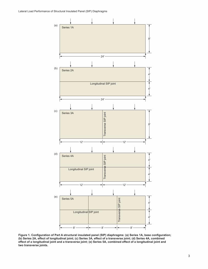
Series 1A served as the basic diaphragm for Part A with the configuration shown in Figure 1a. The diaphragm contained no spline and consisted of one SIP panel with dimensions of 8 by 24 ft.
Series 2A contained one longitudinal joint (block spline) and was constructed with two SIP segments with dimensions of 4 by 24 ft (Fig. 1b). The purpose of this test series was to evaluate the effect of longitudinal joints on lateral load performance of a SIP diaphragm assembly.
Series 3A contained one transverse joint (block spline) and was constructed with two SIP segments with dimensions of 8 by 12 ft (Fig. 1c). The purpose of this test series was to evaluate the effect of a transverse joint on lateral load performance of a SIP diaphragm assembly.
Series 4A contained one longitudinal joint (block spline) and one transverse joint (block spline) and was constructed with four SIP segments with dimensions of 4 by 12 ft (Fig. 1d). The length of the block spline matched the segment size. The purpose of this test series was to evaluate the combined effect of one longitudinal joint and one transverse joint on lateral load performance of a SIP diaphragm assembly.
Series 5A contained one longitudinal joint and two transverse joints. It was constructed with six SIP segments with dimensions of 4 by 8 ft (Fig. 1e). The purpose of this test series was to evaluate the combined effect of one longitudinal joint and two transverse joints on lateral load performance of a SIP diaphragm assembly.
Part B: SIP Diaphragms Connected to Framing
The purpose of Part B was to evaluate the capacities of SIP diaphragms connected to framing with SIP screws supplied by the SIP manufacturer. The screws had a head diameter of 0.635 in., thread diameter of 0.245 to 0.255 in., and shank diameter of 0.190 to 0.212 in. The commonality for all test series in this part included the following:
Assembly size: 8 by 24 ft
SIP thickness: 8-1/4 in.
Fastener spacing to SIP plates: 8d cooler (0.113 by 2-3/8 in.) nails at 6 in. o.c.
Framing materials: 6 by 6 No. 2 or Better Douglas-fir
Test protocol: ASTM E455 (monotonic)
Replicate: 1
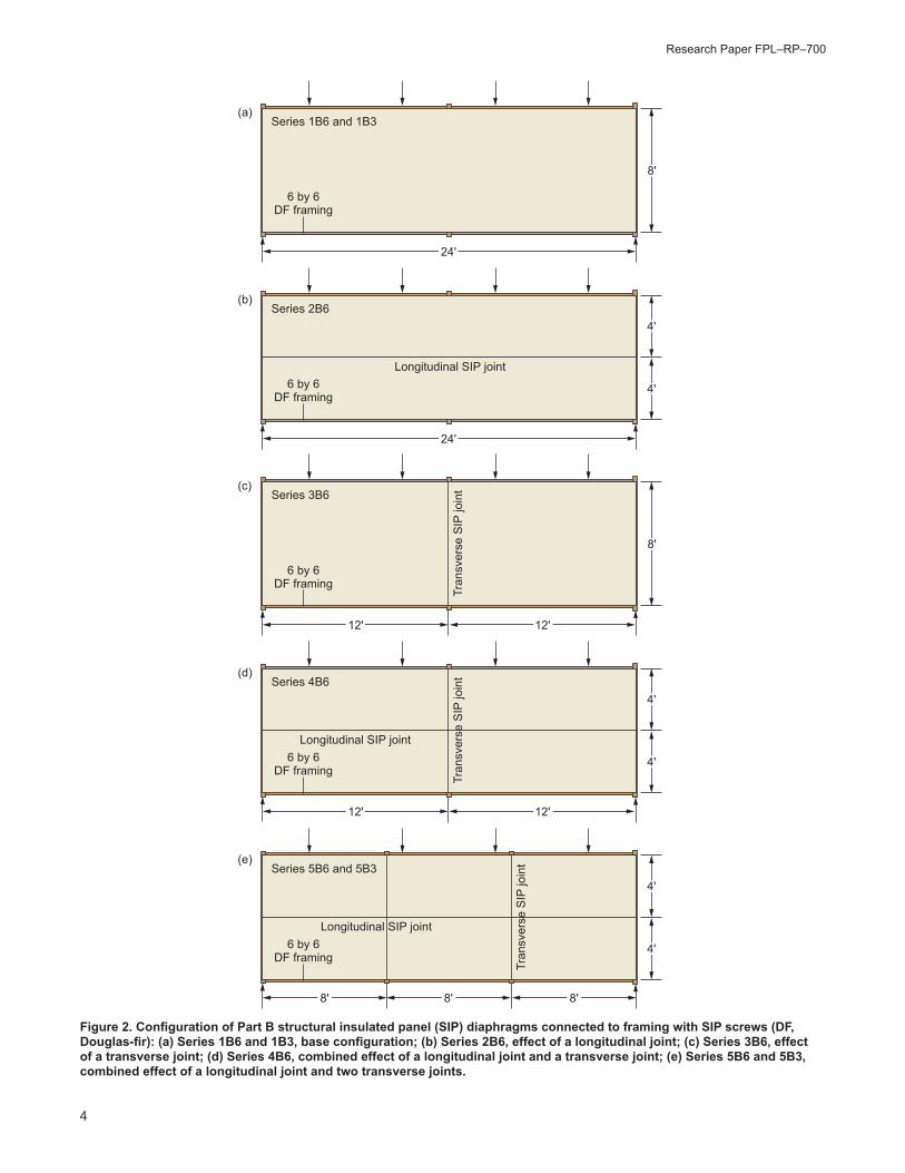
Series 1B6 and 1B3 served as the basic diaphragms for Part B with the basic configuration shown in Figure 2a. The diaphragm contained no spline and consisted of one SIP panel with dimensions of 8 by 24 ft. The diaphragm was fastened to the framing with SIP screws at 6 in. o.c. for Series 1B6 and 3 in. o.c. for Series 1B3.
Series 2B6 contained one longitudinal joint (block spline) and was constructed with two SIP segments with dimensions of 4 by 24 ft (Fig. 2b). The purpose of this test specimen was to evaluate the effect of a longitudinal joint
Table 1—Test matrix for structural testing of full-sized structural insulated panel (SIP) diaphragms (8 by 24 ft) of various configurations (total number of full-scale diaphragms: 12)
Test seriesa
Purpose (compared with basic wall)
No. oftests
SIP segment size (ft) Deviation from basic diaphragm
1A Basic diaphragm for Part A 1 8 by 24 Basic configuration
2A Effect of longitudinal joint 1 4 by 24 Two SIP segments
3A Effect of transverse joint 1 8 by 12 Two SIP segments
4A Effect of longitudinal and transverse joints
1 4 by 12 Four SIP segments
5A 1 4 by 8 Six SIP segments
1B6Basic diaphragm for Part B
1 8 by 24 Basic configuration with 6-in. o.c. SIP screw spacing
1B3 1 8 by 24 Basic configuration with 3-in. o.c. SIP screw spacing
2B6 Effect of longitudinal joint 1 4 by 24 Two SIP segments with 6-in. o.c. SIP screw spacing
3B6 Effect of transverse joint 1 8 by 12 Two SIP segments with 6-in. o.c. SIP screw spacing
4B6Effect of longitudinal, transverse joints, and SIP screw spacing
1 4 by 12 Four SIP segments with 6-in. o.c. SIP screw spacing
5B6 1 4 by 8 Six SIP segments with 6-in. o.c. SIP screw spacing
5B3 1 4 by 8 Six SIP segments with 3-in. o.c. SIP screw spacingaThe series designation is expressed as nXm, where n is the series number (n = 1–5), X is the part of the study (X = A or B), and m (in Part B only) is the screw spacing in inches (m = 6 or 3).
Lateral Load Performance of Structural Insulated Panel (SIP) Diaphragms
3
Figure 1. Configuration of Part A structural insulated panel (SIP) diaphragms: (a) Series 1A, base configuration; (b) Series 2A, effect of longitudinal joint; (c) Series 3A, effect of a transverse joint; (d) Series 4A, combined effect of a longitudinal joint and a transverse joint; (e) Series 5A, combined effect of a longitudinal joint and two transverse joints.
8'
24'
Series 1A(a)
8'
12' 12'
Series 3A(c)
4'
4'
4'
4'
24'
Series 2A(b)
Longitudinal SIP joint
Longitudinal SIP joint
Tran
sver
se S
IP jo
int
12' 12'
Series 4A(d)
Tran
sver
se S
IP jo
int
4'
4'
Longitudinal SIP joint
8' 8' 8'
Series 5A(e)
Tran
sver
se S
IP jo
int
Research Paper FPL–RP–700
4
Figure 2. Configuration of Part B structural insulated panel (SIP) diaphragms connected to framing with SIP screws (DF, Douglas-fir): (a) Series 1B6 and 1B3, base configuration; (b) Series 2B6, effect of a longitudinal joint; (c) Series 3B6, effect of a transverse joint; (d) Series 4B6, combined effect of a longitudinal joint and a transverse joint; (e) Series 5B6 and 5B3, combined effect of a longitudinal joint and two transverse joints.
8'
24'
Series 1B6 and 1B3
6 by 6DF framing
(a)
8'
12' 12'
Series 3B6(c)
4'
4'
4'
4'
24'
Series 2B6(b)
Longitudinal SIP joint
Longitudinal SIP joint
Tran
sver
se S
IP jo
int
12' 12'
Series 4B6(d)
Tran
sver
se S
IP jo
int
4'
4'
Longitudinal SIP joint
8' 8' 8'
Series 5B6 and 5B3(e)
Tran
sver
se S
IP jo
int
6 by 6DF framing
6 by 6DF framing
6 by 6DF framing
6 by 6DF framing
Lateral Load Performance of Structural Insulated Panel (SIP) Diaphragms
5
on lateral load performance of a SIP diaphragm assembly with framing.
Series 3B6 contained one transverse joint (block spline) and was constructed with two SIP segments with dimensions of 8 by 12 ft (Fig. 2c). The purpose of this test series was to evaluate the effect of a transverse joint on lateral load performance of a SIP diaphragm assembly with framing.
Series 4B6 contained one longitudinal joint (block spline) and one transverse joint (block spline) and was constructed with four SIP segments with dimensions of 4 by 12 ft (Fig. 2d). The purpose of this test series was to evaluate the combined effect of one longitudinal joint and one transverse joint on lateral load performance of a SIP diaphragm assembly with framing.
Series 5B6 and 5B3 each contained one longitudinal joint and two transverse joints. They were constructed with six SIP segments with dimensions of 4 by 8 ft (Fig. 2e). The diaphragms were fastened to the framing with SIP screws at 6 in. o.c. for Series 5B6 and 3 in. o.c. for Series 5B3. The purpose of these test series was to evaluate the combined effects of one longitudinal joint and two transverse joints and SIP screw spacing on lateral load performance of a SIP diaphragm assembly with framing.
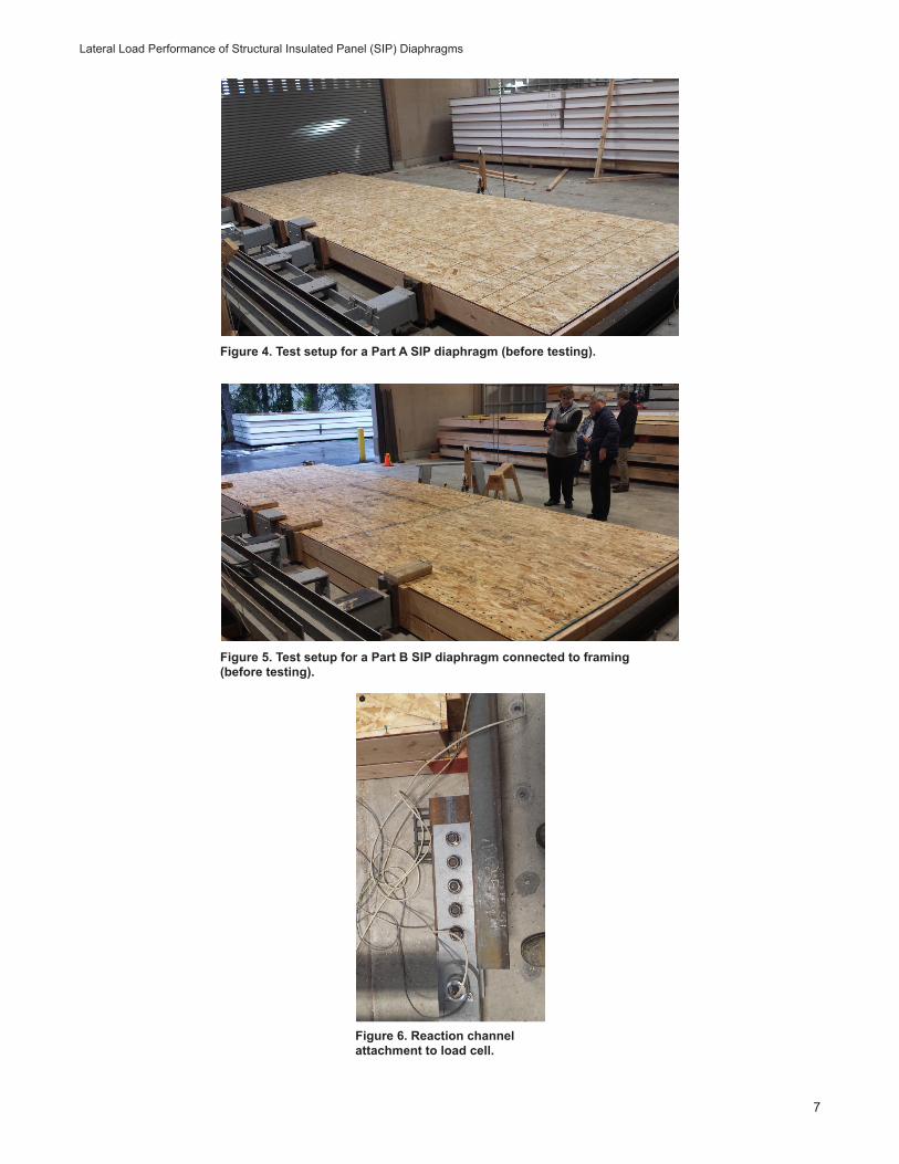
SIP Diaphragm TestingThe SIP diaphragms were constructed and tested at the APA Research Center in Tacoma, Washington, USA, which is accredited under ISO/IEC 17025 (ISO/IEC 2017). The static load testing of each SIP diaphragm was conducted following a monotonic procedure specified in ASTM E455-16 (ASTM 2016) using a loading rate that reached the ultimate load in approximately 10 min. Figure 3a shows the diaphragm plan view for structural testing of diaphragms, along with the loading configuration; Figure 3b shows details of diaphragm boundary A-A; Figure 3c shows details of diaphragm boundary B-B; and Figure 3d shows the spline detail C-C. Test setup for Part A diaphragms (before testing) and Part B diaphragms connected to framing (before testing) are shown in Figures 4 and 5, respectively.
The attachment mechanism of the diaphragm into one of the steel reaction channels is shown in Figure 3b. The steel channels were connected to tension reaction rods that were mounted to rigid reactions. In this tension train, a 75-kip load cell was placed inline (Fig. 6). A load cell was located at each end of the diaphragm. The reported loads were based on the average value of two load cells divided by the diaphragm depth of 8 ft to convert to a unit shear value in pounds of force per foot. A linear potentiometer was mounted midspan on the 2 by 8 chord for each tested diaphragm to capture the diaphragm deflection.
For Part A diaphragms, the reaction load path was from the diaphragm through two 2 by 8s that were attached to the steel channels via Simpson SDS screws (Simpson
Strong-Tie Co., Inc., Pleasanton, California, USA) (Fig. 3b, left). The SIP sheathing nails were only attached to the interior 2 by 8. The exterior 2 by 8 was used as a spacer to prevent the sheathing from directly bearing on the reaction channels. Based on previous SIP tests, when sheathing comes into contact with the test frame, the peak loads and ultimate deflections are affected. Although there was a 6 by 6 that was supporting the diaphragm, for the Part A tests, this wood member only served as a spacer to maintain the same elevation for all diaphragms for ease of applying the four-point loads.
For the Part B diaphragms, the SDS screws connected the reaction channel to the 6 by 6 wood members (Fig. 3b, right). The diaphragm sheathing was nailed similarly to Part A, with SIP sheathing nails installed on both sides of the diaphragm. The diaphragm was attached to the 6 by 6 member with SIP screws at either 6 or 3 in. o.c.
Figure 3c shows the boundary details for Parts A and B on the 24-ft-long sides of the diaphragm. Figure 3d provides a spline detail for those diaphragms that had splines in both Parts A and B. As often occurs in the field, the spline was only nailed on one side of the diaphragm, but the nail spacing was doubled to transfer the entire shear force of the diaphragm through the top of the box spline.
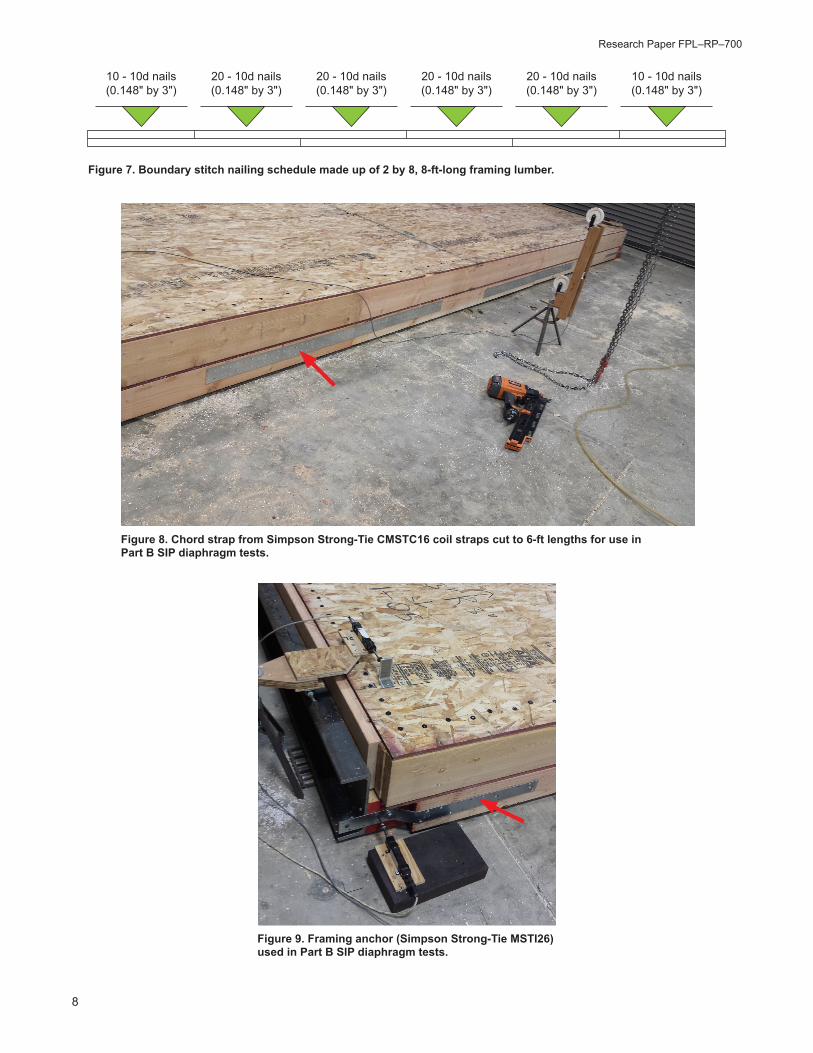
Figure 7 shows the stitch nail spacing of the diaphragm chords for the double discontinuous 2 by 8 framing. For the Part B diaphragms, additional chord splices for the 6 by 6s were provided (Fig. 8). Additional framing connectors were used to attach the 6 by 6s that met at a 90° angle on the diaphragm corners (Fig. 9).
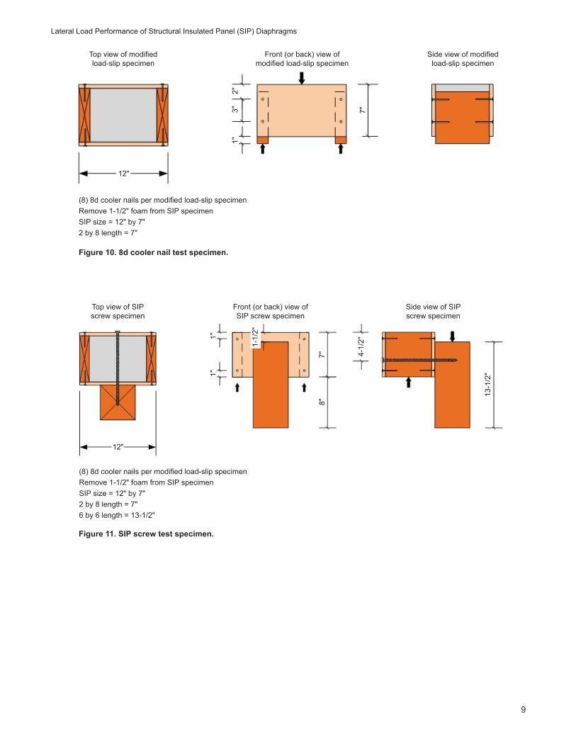
Supplemental Fastener TestsSupplemental mechanical tests were conducted to determine the fastener yield strength of the SIP screws and the 8d cooler nails (0.113 by 2-3/8 in.) in accordance with ASTM F1575 (ASTM 2017b) because the bending yield strength of the SIP screws could affect the diaphragm shear strength. In addition, the lateral resistance of the 8d cooler nails was determined following a load-slip test method for establishing the sheathing to framing nail characteristics. In total, eight 8d cooler nails were driven into 2 by 8 Douglas-fir lumber. Figure 10 shows a drawing of the load-slip test specimen.
Lateral resistance of SIP screws was determined following the principles of ASTM D1761 (ASTM 2012). Figure 11 shows a drawing of the SIP screw test specimen. The SIP screws were screwed through the SIP into 6 by 6 Douglas-fir timber. All fastener tests were monotonic using the loading rate in the referenced ASTM standards.
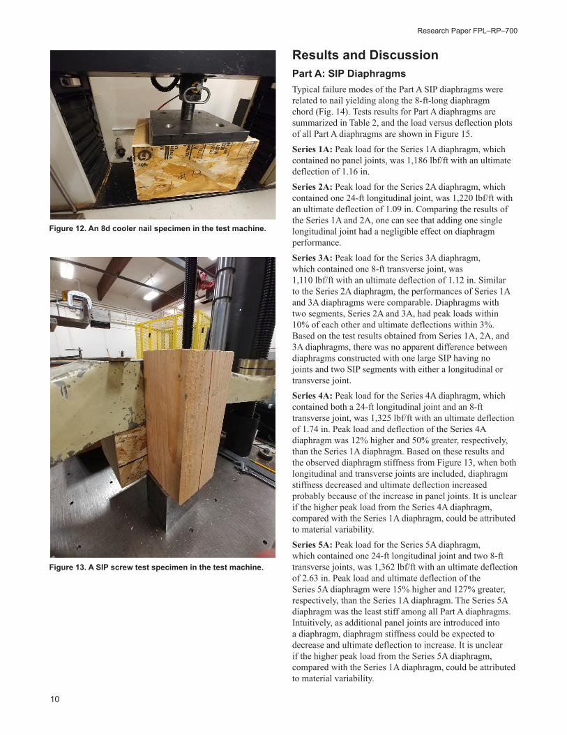
An 8d cooler nail test specimen and a SIP screw test specimen in the test machine are shown in Figures 12 and 13, respectively.
Research Paper FPL–RP–700
6
figs 3 through 11
Figure 3. Diaphragm plan view for lateral load testing of structural insulated panel (SIP) diaphragms: (a) diaphragm plan view showing the loading configuration of diaphragm testing; (b) diaphragm boundary A-A showing reaction attachment scheme for Part A (left) and Part B (right) at the 8-ft boundary framing; (c) diaphragm boundary B-B showing reaction attachment scheme for Part A (left) and Part B (right) at the 24-ft boundary framing; and (d) spline detail C-C for Part A (left) and Part B (right) framing.
(a)
(b)
(c)
(d)
Diaphragm plan view
Detail C-C for Part A(spline)
Detail C-C for Part B(spline)
8d cooler (0.113" by 2-3/8") at 6" o.c.
Detail A-A for Part A(8' boundary)
Detail A-A for Part B(8' boundary)
30 - 10d common (0.148" by 3") stitch
nails (evenly spaced)
20 - SDS screws (0.25" by 3-1/2" (evenly
spaced)1"
14-3
/4"
8d cooler (0.113" by 2-3/8") at 3" o.c.
(no nails on bottom)SIP screws, both sides of joint at
12" o.c.
8d cooler (0.113" by 2-3/8") at 6" o.c.
10d common (0.148" by 3") stitch nails
(see Plan View D for nail schedule)
Detail B-B for Part A(24' boundary)
Detail B-B for Part B(24' boundary)
P/2 P/4
4'
8'
6' 4' 6' 4'
P/4 P/4 P/4 P/2
12' 12'
C C
A A
BB
Lateral Load Performance of Structural Insulated Panel (SIP) Diaphragms
7
Figure 4. Test setup for a Part A SIP diaphragm (before testing).
Figure 5. Test setup for a Part B SIP diaphragm connected to framing (before testing).
Figure 6. Reaction channel attachment to load cell.
Research Paper FPL–RP–700
8
Figure 7. Boundary stitch nailing schedule made up of 2 by 8, 8-ft-long framing lumber.
Figure 8. Chord strap from Simpson Strong-Tie CMSTC16 coil straps cut to 6-ft lengths for use in Part B SIP diaphragm tests.
Figure 9. Framing anchor (Simpson Strong-Tie MSTI26) used in Part B SIP diaphragm tests.
10 - 10d nails(0.148" by 3")
20 - 10d nails(0.148" by 3")
20 - 10d nails(0.148" by 3")
20 - 10d nails(0.148" by 3")
20 - 10d nails(0.148" by 3")
10 - 10d nails(0.148" by 3")
Lateral Load Performance of Structural Insulated Panel (SIP) Diaphragms
9
Figure 10. 8d cooler nail test specimen.
Figure 11. SIP screw test specimen.
12"
Top view of modified load-slip specimen
Front (or back) view of modified load-slip specimen
Side view of modified load-slip specimen
2"3" 7"
1"
(8) 8d cooler nails per modified load-slip specimenRemove 1-1/2" foam from SIP specimenSIP size = 12" by 7"2 by 8 length = 7"
(8) 8d cooler nails per modified load-slip specimenRemove 1-1/2" foam from SIP specimenSIP size = 12" by 7"2 by 8 length = 7"6 by 6 length = 13-1/2"
12"
1"1"
1-1/
2"
4-1/
2"
7"8"
13-1
/2"
Top view of SIP screw specimen
Front (or back) view of SIP screw specimen
Side view of SIP screw specimen
Research Paper FPL–RP–700
10
Figure 12. An 8d cooler nail specimen in the test machine.
Figure 13. A SIP screw test specimen in the test machine.
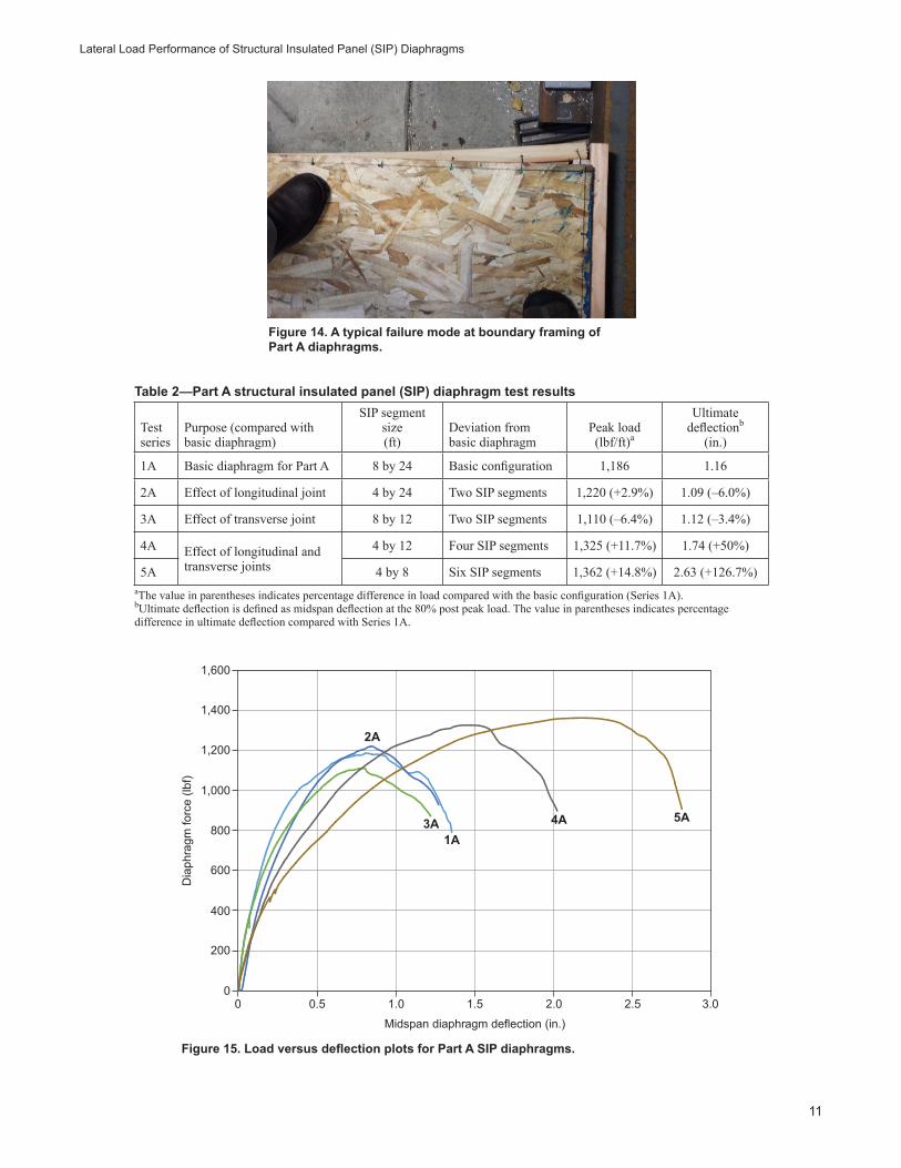
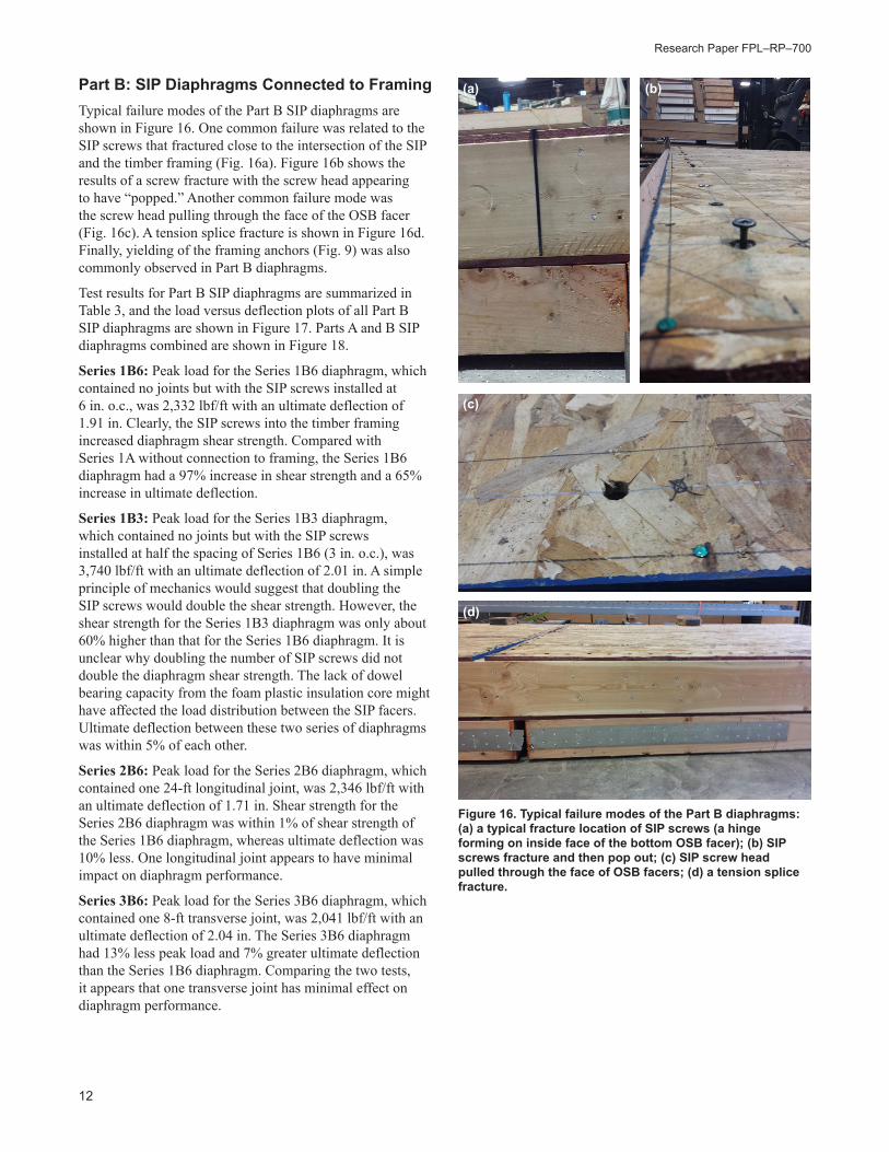
Results and DiscussionPart A: SIP DiaphragmsTypical failure modes of the Part A SIP diaphragms were related to nail yielding along the 8-ft-long diaphragm chord (Fig. 14). Tests results for Part A diaphragms are summarized in Table 2, and the load versus deflection plots of all Part A diaphragms are shown in Figure 15.
Series 1A: Peak load for the Series 1A diaphragm, which contained no panel joints, was 1,186 lbf/ft with an ultimate deflection of 1.16 in.
Series 2A: Peak load for the Series 2A diaphragm, which contained one 24-ft longitudinal joint, was 1,220 lbf/ft with an ultimate deflection of 1.09 in. Comparing the results of the Series 1A and 2A, one can see that adding one single longitudinal joint had a negligible effect on diaphragm performance.
Series 3A: Peak load for the Series 3A diaphragm, which contained one 8-ft transverse joint, was 1,110 lbf/ft with an ultimate deflection of 1.12 in. Similar to the Series 2A diaphragm, the performances of Series 1A and 3A diaphragms were comparable. Diaphragms with two segments, Series 2A and 3A, had peak loads within 10% of each other and ultimate deflections within 3%. Based on the test results obtained from Series 1A, 2A, and 3A diaphragms, there was no apparent difference between diaphragms constructed with one large SIP having no joints and two SIP segments with either a longitudinal or transverse joint.
Series 4A: Peak load for the Series 4A diaphragm, which contained both a 24-ft longitudinal joint and an 8-ft transverse joint, was 1,325 lbf/ft with an ultimate deflection of 1.74 in. Peak load and deflection of the Series 4A diaphragm was 12% higher and 50% greater, respectively, than the Series 1A diaphragm. Based on these results and the observed diaphragm stiffness from Figure 13, when both longitudinal and transverse joints are included, diaphragm stiffness decreased and ultimate deflection increased probably because of the increase in panel joints. It is unclear if the higher peak load from the Series 4A diaphragm, compared with the Series 1A diaphragm, could be attributed to material variability.
Series 5A: Peak load for the Series 5A diaphragm, which contained one 24-ft longitudinal joint and two 8-ft transverse joints, was 1,362 lbf/ft with an ultimate deflection of 2.63 in. Peak load and ultimate deflection of the Series 5A diaphragm were 15% higher and 127% greater, respectively, than the Series 1A diaphragm. The Series 5A diaphragm was the least stiff among all Part A diaphragms. Intuitively, as additional panel joints are introduced into a diaphragm, diaphragm stiffness could be expected to decrease and ultimate deflection to increase. It is unclear if the higher peak load from the Series 5A diaphragm, compared with the Series 1A diaphragm, could be attributed to material variability.
Lateral Load Performance of Structural Insulated Panel (SIP) Diaphragms
11
Figure 14. A typical failure mode at boundary framing of Part A diaphragms.
Figure 15. Load versus deflection plots for Part A SIP diaphragms.
Table 2—Part A structural insulated panel (SIP) diaphragm test results
Test series
Purpose (compared with basic diaphragm)
SIP segment size (ft)
Deviation from basic diaphragm
Peak load (lbf/ft)a
Ultimate deflectionb
(in.)
1A Basic diaphragm for Part A 8 by 24 Basic configuration 1,186 1.16
2A Effect of longitudinal joint 4 by 24 Two SIP segments 1,220 (+2.9%) 1.09 (–6.0%)
3A Effect of transverse joint 8 by 12 Two SIP segments 1,110 (–6.4%) 1.12 (–3.4%)
4A Effect of longitudinal and transverse joints
4 by 12 Four SIP segments 1,325 (+11.7%) 1.74 (+50%)
5A 4 by 8 Six SIP segments 1,362 (+14.8%) 2.63 (+126.7%)aThe value in parentheses indicates percentage difference in load compared with the basic configuration (Series 1A).bUltimate deflection is defined as midspan deflection at the 80% post peak load. The value in parentheses indicates percentage difference in ultimate deflection compared with Series 1A.
0
200
400
600
800
1,000
1,2002A
3A1A
4A 5A
1,400
1,600
Dia
phra
gm fo
rce
(lbf)
Midspan diaphragm deflection (in.)
0 0.5 1.0 1.5 2.0 2.5 3.0
Research Paper FPL–RP–700
12
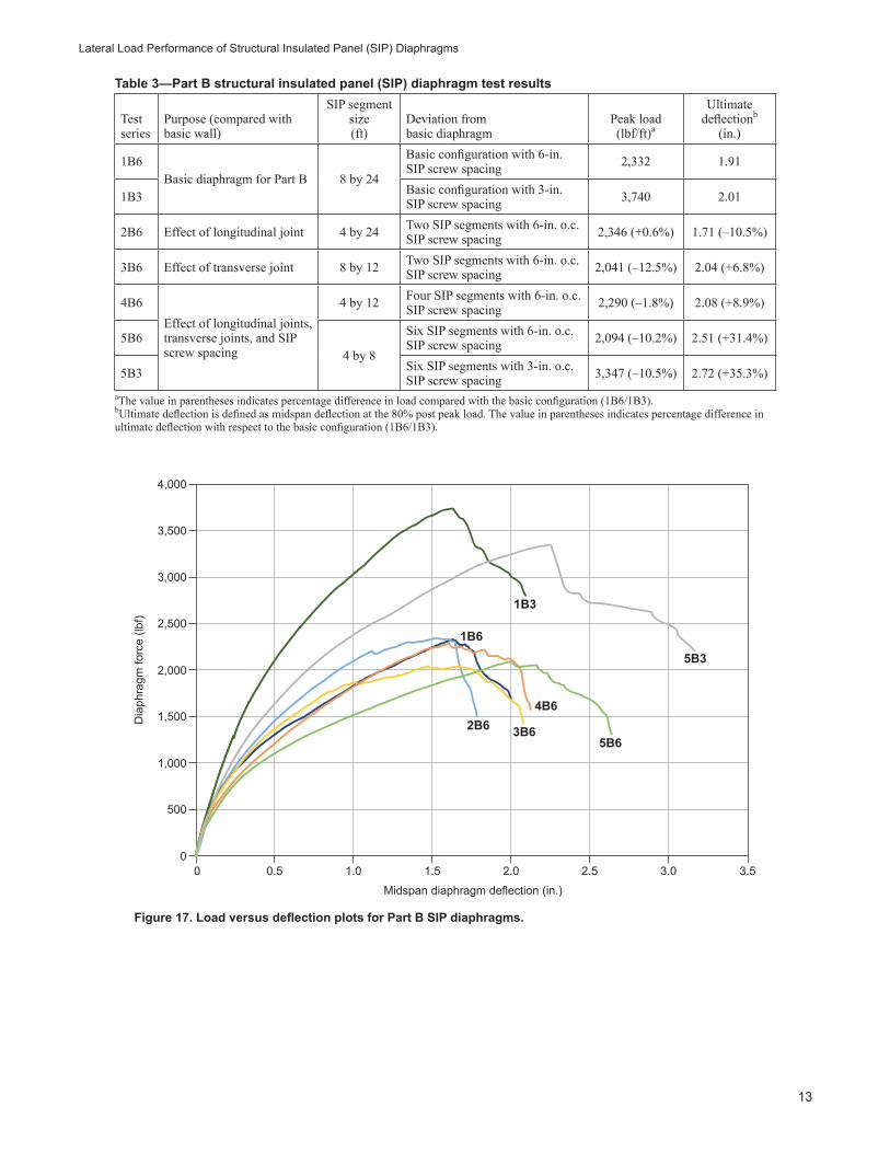
Part B: SIP Diaphragms Connected to FramingTypical failure modes of the Part B SIP diaphragms are shown in Figure 16. One common failure was related to the SIP screws that fractured close to the intersection of the SIP and the timber framing (Fig. 16a). Figure 16b shows the results of a screw fracture with the screw head appearing to have “popped.” Another common failure mode was the screw head pulling through the face of the OSB facer (Fig. 16c). A tension splice fracture is shown in Figure 16d. Finally, yielding of the framing anchors (Fig. 9) was also commonly observed in Part B diaphragms.
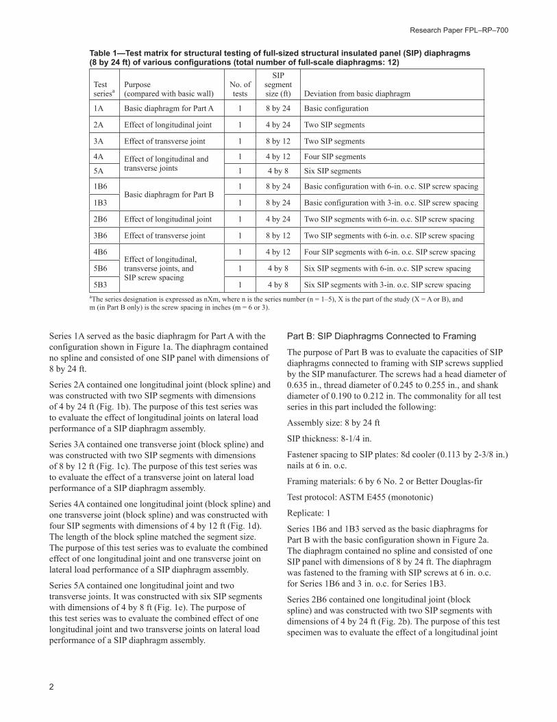
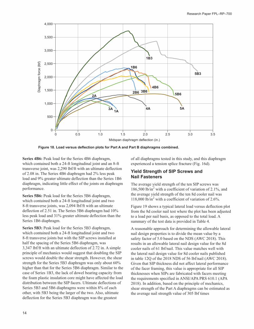
Test results for Part B SIP diaphragms are summarized in Table 3, and the load versus deflection plots of all Part B SIP diaphragms are shown in Figure 17. Parts A and B SIP diaphragms combined are shown in Figure 18.
Series 1B6: Peak load for the Series 1B6 diaphragm, which contained no joints but with the SIP screws installed at 6 in. o.c., was 2,332 lbf/ft with an ultimate deflection of 1.91 in. Clearly, the SIP screws into the timber framing increased diaphragm shear strength. Compared with Series 1A without connection to framing, the Series 1B6 diaphragm had a 97% increase in shear strength and a 65% increase in ultimate deflection.
Series 1B3: Peak load for the Series 1B3 diaphragm, which contained no joints but with the SIP screws installed at half the spacing of Series 1B6 (3 in. o.c.), was 3,740 lbf/ft with an ultimate deflection of 2.01 in. A simple principle of mechanics would suggest that doubling the SIP screws would double the shear strength. However, the shear strength for the Series 1B3 diaphragm was only about 60% higher than that for the Series 1B6 diaphragm. It is unclear why doubling the number of SIP screws did not double the diaphragm shear strength. The lack of dowel bearing capacity from the foam plastic insulation core might have affected the load distribution between the SIP facers. Ultimate deflection between these two series of diaphragms was within 5% of each other.
Series 2B6: Peak load for the Series 2B6 diaphragm, which contained one 24-ft longitudinal joint, was 2,346 lbf/ft with an ultimate deflection of 1.71 in. Shear strength for the Series 2B6 diaphragm was within 1% of shear strength of the Series 1B6 diaphragm, whereas ultimate deflection was 10% less. One longitudinal joint appears to have minimal impact on diaphragm performance.
Series 3B6: Peak load for the Series 3B6 diaphragm, which contained one 8-ft transverse joint, was 2,041 lbf/ft with an ultimate deflection of 2.04 in. The Series 3B6 diaphragm had 13% less peak load and 7% greater ultimate deflection than the Series 1B6 diaphragm. Comparing the two tests, it appears that one transverse joint has minimal effect on diaphragm performance.
Figure 16. Typical failure modes of the Part B diaphragms: (a) a typical fracture location of SIP screws (a hinge forming on inside face of the bottom OSB facer); (b) SIP screws fracture and then pop out; (c) SIP screw head pulled through the face of OSB facers; (d) a tension splice fracture.
(a)
(c)
(d)
(b)
Lateral Load Performance of Structural Insulated Panel (SIP) Diaphragms
13
Figure 17. Load versus deflection plots for Part B SIP diaphragms.
Table 3—Part B structural insulated panel (SIP) diaphragm test results
Test series
Purpose (compared with basic wall)
SIP segment size (ft)
Deviation from basic diaphragm
Peak load (lbf/ft)a
Ultimate deflectionb
(in.)
1B6Basic diaphragm for Part B 8 by 24
Basic configuration with 6-in. SIP screw spacing 2,332 1.91
1B3 Basic configuration with 3-in. SIP screw spacing 3,740 2.01
2B6 Effect of longitudinal joint 4 by 24 Two SIP segments with 6-in. o.c. SIP screw spacing 2,346 (+0.6%) 1.71 (–10.5%)
3B6 Effect of transverse joint 8 by 12 Two SIP segments with 6-in. o.c. SIP screw spacing 2,041 (–12.5%) 2.04 (+6.8%)
4B6Effect of longitudinal joints, transverse joints, and SIP screw spacing
4 by 12 Four SIP segments with 6-in. o.c. SIP screw spacing 2,290 (–1.8%) 2.08 (+8.9%)
5B64 by 8
Six SIP segments with 6-in. o.c. SIP screw spacing 2,094 (–10.2%) 2.51 (+31.4%)
5B3 Six SIP segments with 3-in. o.c. SIP screw spacing 3,347 (–10.5%) 2.72 (+35.3%)
aThe value in parentheses indicates percentage difference in load compared with the basic configuration (1B6/1B3).bUltimate deflection is defined as midspan deflection at the 80% post peak load. The value in parentheses indicates percentage difference in ultimate deflection with respect to the basic configuration (1B6/1B3).
0
500
1,000
1,500
2,000
2,500
3,000
3,500
4,000
Dia
phra
gm fo
rce
(lbf)
Midspan diaphragm deflection (in.)
0 0.5 1.0 1.5 2.0 2.5 3.0 3.5
2B6
1B6
1B3
5B3
3B6
4B6
5B6
Research Paper FPL–RP–700
14
Series 4B6: Peak load for the Series 4B6 diaphragm, which contained both a 24-ft longitudinal joint and an 8-ft transverse joint, was 2,290 lbf/ft with an ultimate deflection of 2.08 in. The Series 4B6 diaphragm had 2% less peak load and 9% greater ultimate deflection than the Series 1B6 diaphragm, indicating little effect of the joints on diaphragm performance.
Series 5B6: Peak load for the Series 5B6 diaphragm, which contained both a 24-ft longitudinal joint and two 8-ft transverse joints, was 2,094 lbf/ft with an ultimate deflection of 2.51 in. The Series 5B6 diaphragm had 10% less peak load and 31% greater ultimate deflection than the Series 1B6 diaphragm.
Series 5B3: Peak load for the Series 5B3 diaphragm, which contained both a 24-ft longitudinal joint and two 8-ft transverse joints but with the SIP screws installed at half the spacing of the Series 5B6 diaphragm, was 3,347 lbf/ft with an ultimate deflection of 2.72 in. A simple principle of mechanics would suggest that doubling the SIP screws would double the shear strength. However, the shear strength for the Series 5B3 diaphragm was only about 60% higher than that for the Series 5B6 diaphragm. Similar to the case of Series 1B3, the lack of dowel bearing capacity from the foam plastic insulation core might have affected the load distribution between the SIP facers. Ultimate deflections of Series 5B3 and 5B6 diaphragms were within 8% of each other, with 5B3 being the larger of the two. Also, ultimate deflection for the Series 5B3 diaphragm was the greatest
Figure 18. Load versus deflection plots for Part A and Part B diaphragms combined.
of all diaphragms tested in this study, and this diaphragm experienced a tension splice fracture (Fig. 16d).
Yield Strength of SIP Screws and Nail FastenersThe average yield strength of the ten SIP screws was 186,500 lb/in2 with a coefficient of variation of 2.1%, and the average yield strength of the ten 8d cooler nail was 118,000 lb/in2 with a coefficient of variation of 2.6%.
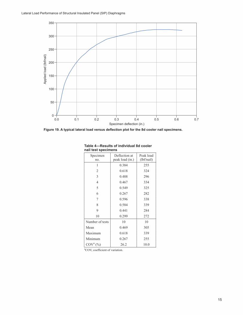
Figure 19 shows a typical lateral load versus deflection plot from the 8d cooler nail test where the plot has been adjusted to a load per nail basis, as opposed to the total load. A summary of the test data is provided in Table 4.
A reasonable approach for determining the allowable lateral nail design properties is to divide the mean value by a safety factor of 5.0 based on the NDS (AWC 2018). This results in an allowable lateral nail design value for the 8d cooler nails of 61 lbf/nail. This value matches well with the lateral nail design value for 8d cooler nails published in table 12Q of the 2018 NDS of 56 lbf/nail (AWC 2018). Given that SIP thickness did not affect lateral performance of the facer framing, this value is appropriate for all SIP thicknesses when SIPs are fabricated with facers meeting the requirements specified in ANSI/APA PRS 610.1 (APA 2018). In addition, based on the principle of mechanics, shear strength of the Part A diaphragms can be estimated as the average nail strength value of 305 lbf times
0
500
1,000
1,500
2,000
2,500
3,000
3,500
4,000
Dia
phra
gm fo
rce
(lbf)
Midspan diaphragm deflection (in.)
0 0.5 1.0 1.5 2.0 2.5 3.0 3.5
2B6
1B6
1B3
5B3
4B6
5B63B6
3A 1A
2A
4A 5A
Lateral Load Performance of Structural Insulated Panel (SIP) Diaphragms
15
Figure 19. A typical lateral load versus deflection plot for the 8d cooler nail specimens.
Table 4—Results of individual 8d cooler nail test specimens
Specimen no.
Deflection at peak load (in.)
Peak load (lbf/nail)
1 0.384 2552 0.618 3243 0.488 2964 0.467 3345 0.549 3256 0.267 2827 0.596 3388 0.584 3399 0.441 28410 0.299 272
Number of tests 10 10Mean 0.469 305Maximum 0.618 339Minimum 0.267 255COVa (%) 26.2 10.0
aCOV, coefficient of variation.
50
100
150
0.0 0.1 0.2 0.3Specimen deflection (in.)
App
lied
load
(lbf
/nai
l)
0.4 0.5 0.6 0.7
200
250
300
350
0
Research Paper FPL–RP–700
16
4 nails/ft, which yields an ultimate unit shear of 1,220 lbf/ft. This estimated value agrees well with the observed load values from Part A diaphragms (Table 2). This analysis was based on ultimate loads with multiple nails, and the diaphragm factor, Cdi, of 1.1 (as defined in section 12.5.3 of the 2018 NDS) was not used. Nonetheless, it is interesting that the NDS published value of 56 lbf/nail times a diaphragm factor of 1.1 leads to an allowable lateral nail design value of 62 lbf/nail, which compares well with the value of 61 lbf/nail obtained from this study.
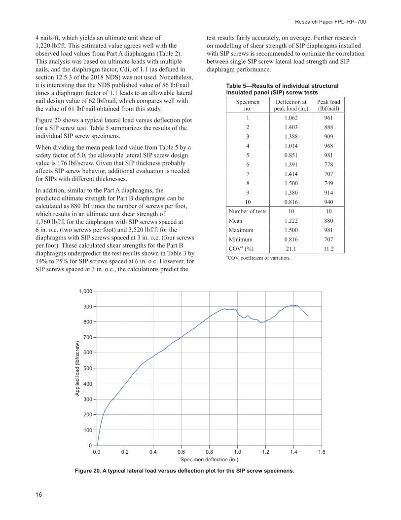
Figure 20 shows a typical lateral load versus deflection plot for a SIP screw test. Table 5 summarizes the results of the individual SIP screw specimens.
When dividing the mean peak load value from Table 5 by a safety factor of 5.0, the allowable lateral SIP screw design value is 176 lbf/screw. Given that SIP thickness probably affects SIP screw behavior, additional evaluation is needed for SIPs with different thicknesses.
In addition, similar to the Part A diaphragms, the predicted ultimate strength for Part B diaphragms can be calculated as 880 lbf times the number of screws per foot, which results in an ultimate unit shear strength of 1,760 lbf/ft for the diaphragm with SIP screws spaced at 6 in. o.c. (two screws per foot) and 3,520 lbf/ft for the diaphragms with SIP screws spaced at 3 in. o.c. (four screws per foot). These calculated shear strengths for the Part B diaphragms underpredict the test results shown in Table 3 by 14% to 25% for SIP screws spaced at 6 in. o.c. However, for SIP screws spaced at 3 in. o.c., the calculations predict the
Figure 20. A typical lateral load versus deflection plot for the SIP screw specimens.
Table 5—Results of individual structural insulated panel (SIP) screw tests
Specimen no.
Deflection at peak load (in.)
Peak load (lbf/nail)
1 1.062 9612 1.403 8883 1.388 9094 1.014 9685 0.851 9816 1.391 7787 1.414 7078 1.500 7499 1.380 91410 0.816 940
Number of tests 10 10Mean 1.222 880Maximum 1.500 981Minimum 0.816 707COVa (%) 21.1 11.2
aCOV, coefficient of variation.
test results fairly accurately, on average. Further research on modelling of shear strength of SIP diaphragms installed with SIP screws is recommended to optimize the correlation between single SIP screw lateral load strength and SIP diaphragm performance.
100
300
200
400
0.0 0.2 0.80.60.4Specimen deflection (in.)
App
lied
load
(lbf
/scr
ew)
1.0 1.2 1.4 1.6
600
500
700
900
1,000
0
800
Lateral Load Performance of Structural Insulated Panel (SIP) Diaphragms
17
Summary and ConclusionsPart A DiaphragmsShear strength of SIP diaphragms alone can be reasonably estimated using single fastener lateral strength and the principles of engineering mechanics.
A difference between SIP diaphragms constructed with one segment and two segments could not be detected with the limited tests conducted in this study.
There was a positive correlation between ultimate deflection and number of SIP segments. Although a difference between one segment and two segments was not discernible, a significant increase in ultimate deflection was noted when the segment number was increased to four and six.
There did not appear to be an apparent impact on diaphragm shear strength with a change in the number of SIP segments.
Part B DiaphragmsShear strength of SIP diaphragms connected to framing was underpredicted by 14% to 25% using single SIP screw lateral strength and the principles of engineering mechanics for screw spacing of 6 in. o.c. However, for screw spacing of 3 in. o.c., values were well-predicted on average.
Increasing the number of SIP screws from a spacing of 6 in. to 3 in. o.c. resulted in a 60% increase in the diaphragm shear strength. It is unclear why doubling the number of SIP screws did not double the diaphragm shear strength.
There did not appear to be an impact on diaphragm shear strength with a change in the number of SIP segments when SIPs were connected to framing.
Stiffness of SIP diaphragms can be correlated to the number of SIP segments used in the diaphragm. As the number of SIP segments increased, SIP diaphragm stiffness decreased.
AcknowledgmentsThis project is a cooperative effort between APA – The Engineered Wood Association; the USDA Forest Service, Forest Products Laboratory; and the Structural Insulated Panel Association (SIPA). This research is partially funded by the Forest Products Laboratory through the Coalition for Advanced Wood Structures (CAWS) (16-JV-11111133-039). CAWS brings together representatives from universities, industry, and government to work together in a cooperative, complementary manner to foster sustainable, efficient use of forest resources while improving the economy and performance of wood structures.
Literature CitedAPA. 2018. Standard for performance-rated structural insulated panels in wall applications. ANSI/APA PRS 610.1. Tacoma, WA: APA – The Engineered Wood Association.
ASTM. 2012. ASTM D1761-12. Standard test methods for mechanical fasteners in wood. West Conshohocken, PA: American Society for Testing and Materials International.
ASTM. 2016. ASTM E455-16. Standard test method for static load testing of framed floor or roof diaphragm constructions for buildings. West Conshohocken, PA: American Society for Testing and Materials International.
ASTM. 2017a. ASTM D7446-09. Standard specification for structural insulated panel (SIP) adhesives for laminating oriented strand board (OSB) to rigid cellular polystyrene thermal insulation core materials. West Conshohocken, PA: American Society for Testing and Materials International.
ASTM. 2017b. ASTM F1575-17. Standard test methods for determining bending yield moment of nails. West Conshohocken, PA: American Society for Testing and Materials International.
ASTM. 2018. ASTM C578-18. Standard specification for rigid, cellular polystyrene thermal insulation. West Conshohocken, PA: American Society for Testing and Materials International.
AWC. 2015. Special design provisions for wind and seismic. Leesburg, VA: American Wood Council.
AWC. 2018. National design specification for wood construction. Leesburg, VA: American Wood Council.
ISO/IEC. 2017. General requirements for the competence of testing and calibration laboratories. ISO/IEC 17025. 3rd ed. Geneva, Switzerland: International Organization for Standardization and the International Electrotechnical Commission. 30 p.
Yeh, B.; Skaggs, T.; Wang, X.; Williamson, T. 2018. Lateral load performance of SIP walls with full bearing. Gen. Tech. Rep. FPL-GTR-251. Madison, WI: U.S. Department of Agriculture, Forest Service, Forest Products Laboratory. 23 p.