Latent-Image Flaggingweb.ipac.caltech.edu/staff/fmasci/home/sirtfwork/latimflag_talk2.pdf · IRAC...
6
Frank Masci (1) IRAC D/L Review (S6), August 24, 2001 Latent-Image Flagging Frank Masci August 24, 2001
Transcript of Latent-Image Flaggingweb.ipac.caltech.edu/staff/fmasci/home/sirtfwork/latimflag_talk2.pdf · IRAC...
Frank Masci (1)IRAC D/L Review (S6), August 24, 2001
Latent-Image Flagging
Frank Masci
August 24, 2001
Frank Masci (2)IRAC D/L Review (S6), August 24, 2001
Preliminaries
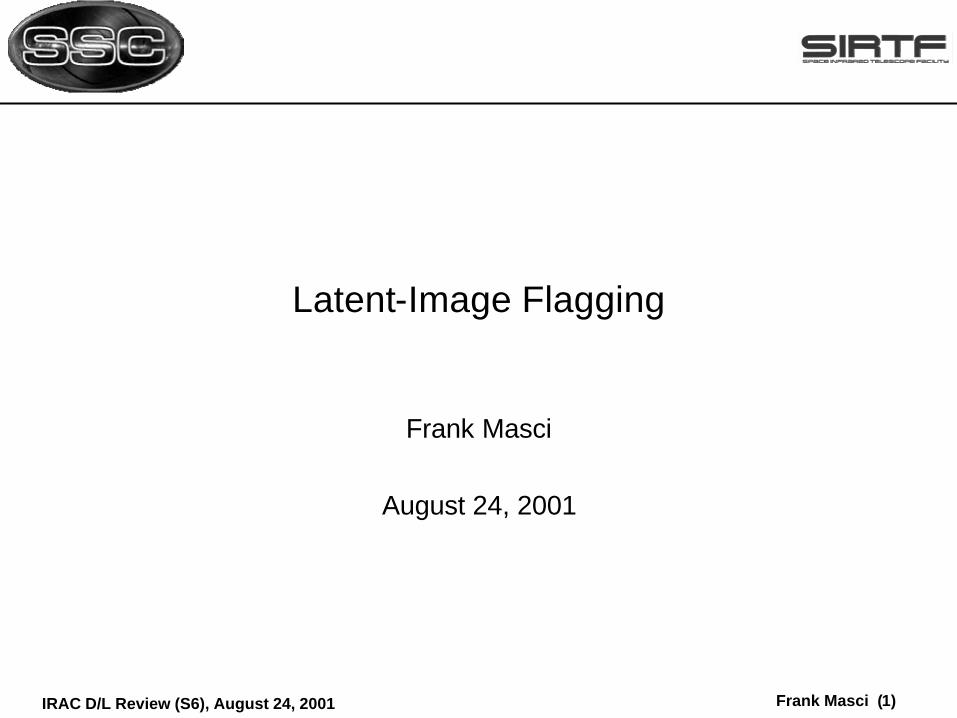
l AIM: To self-consistently flag pixels containing a latent by predicting forward in time which pixel intensities in an ensemble of images are likely to persist as latents in subsequent images of the ensemble.
l Will be performed at the post BCD level and comprise a BQD product.
l Main products: ¤ Each BCD will have an accompanying 8-bit FITS image (called an L-
mask) which specifies latent pixels with the value “1” and “0” if not.¤ For storage limitations, L-mask is only produced if latents are found.¤ A table which reports latent-pixel locations.
l Will involve ensemble processing of BCDs within a single AOR. There will be no crossing of AOR boundaries.
Frank Masci (3)IRAC D/L Review (S6), August 24, 2001
Proposed Algorithm
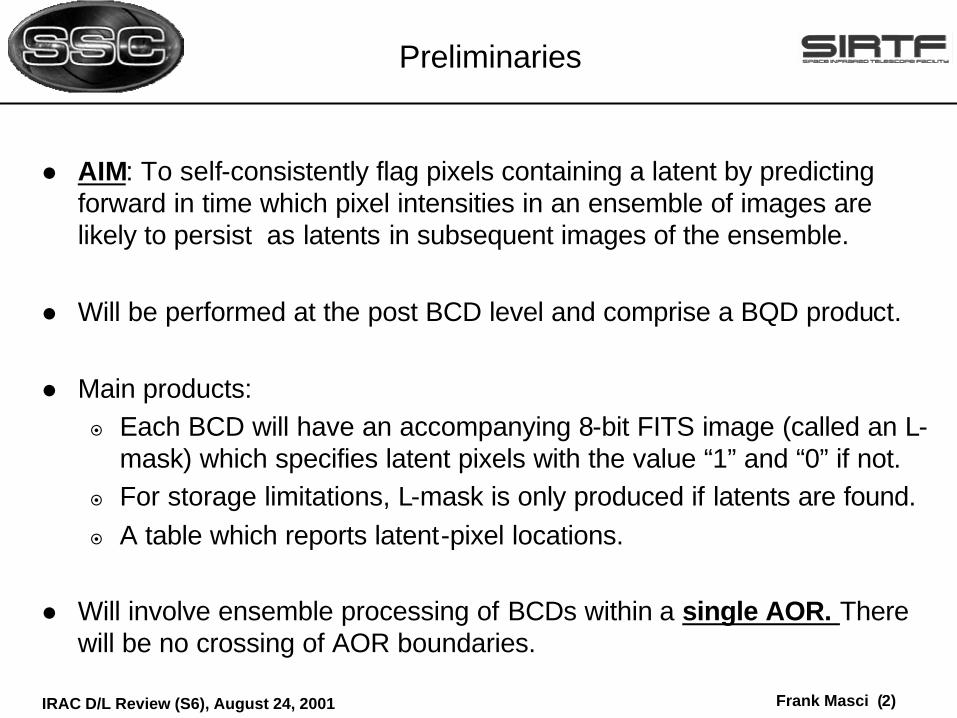
T1 T2 T3 TL
Latents?
T4
Step 1:l From a latent decay model, compute the pixel threshold intensity (or total
count) DNthres i in each image i of the AOR ensemble which will produce a latent above some noise level in all subsequent images.
l The predicted latent intensity has following functional dependence:
¤ TL = Total time between resets in latent-reporting image (i.e. “frame time”). This determines the number of (latent) charge traps released.
,),,T()( LiiLipred TDNfLDN ∆=
Frank Masci (4)IRAC D/L Review (S6), August 24, 2001
Algorithm continued..
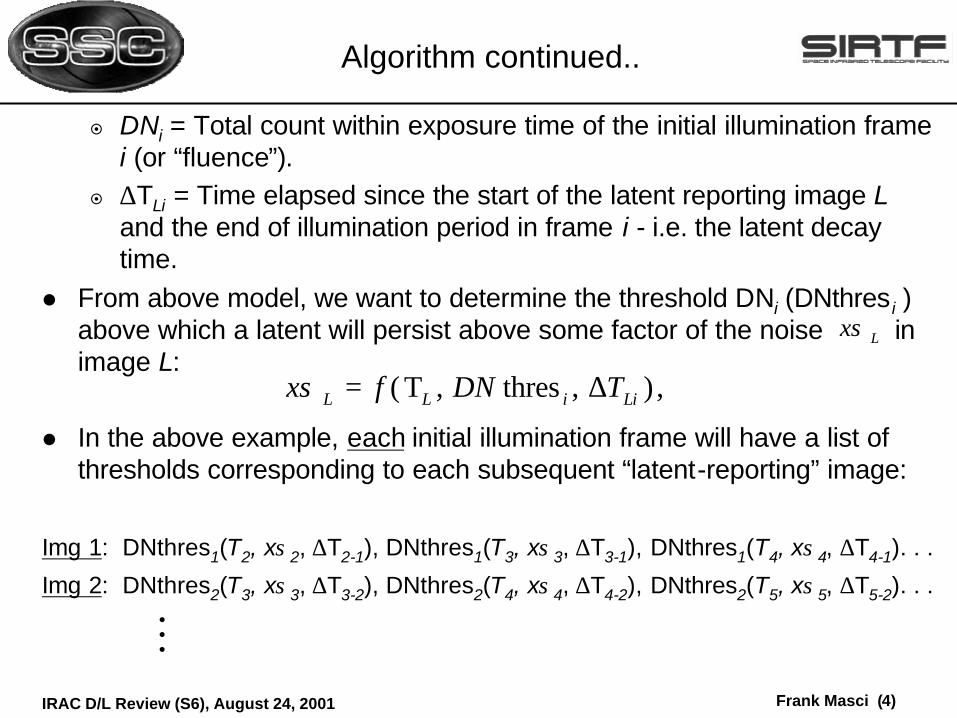
¤ DNi = Total count within exposure time of the initial illumination framei (or “fluence”).
¤ ∆TLi = Time elapsed since the start of the latent reporting image L and the end of illumination period in frame i - i.e. the latent decay time.
l From above model, we want to determine the threshold DNi (DNthres i ) above which a latent will persist above some factor of the noise in image L:
l In the above example, each initial illumination frame will have a list of thresholds corresponding to each subsequent “latent-reporting” image:
Img 1: DNthres1(T2, xσ2, ∆T2-1), DNthres1(T3, xσ3, ∆T3-1), DNthres1(T4, xσ4, ∆T4-1). . .
Img 2: DNthres2(T3, xσ3, ∆T3-2), DNthres2(T4, xσ4, ∆T4-2), DNthres2(T5, xσ5, ∆T5-2). . .
Lxσ
,),thres,T( LiiLL TDNfx ∆=σ
M

Frank Masci (5)IRAC D/L Review (S6), August 24, 2001
Algorithm continued..
Step 2:l Flag all “suspected” latent pixels in each image of the ensemble by
flagging those pixels in the preceding illumination images that have a total count (fluence) above the corresponding predicted thresholds.
l In the above example, suppose we desire a latent image report for image number 4 in the ensemble. This will be accomplished by flagging all pixels in images 1 -- 3 which have a total count:
DN > DNthres1(T4, xσ4, ∆T4-1).&
DN > DNthres2(T4, xσ4, ∆T4-2).&
DN > DNthres3(T4, xσ4, ∆T4-3).
Frank Masci (6)IRAC D/L Review (S6), August 24, 2001
Require from Instrument Team
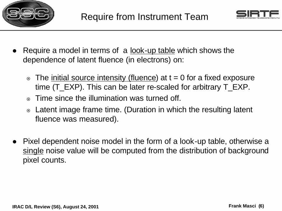
l Require a model in terms of a look-up table which shows the dependence of latent fluence (in electrons) on:
¤ The initial source intensity (fluence) at t = 0 for a fixed exposure time (T_EXP). This can be later re-scaled for arbitrary T_EXP.
¤ Time since the illumination was turned off.¤ Latent image frame time. (Duration in which the resulting latent
fluence was measured).
l Pixel dependent noise model in the form of a look-up table, otherwise a single noise value will be computed from the distribution of background pixel counts.