Lastenheft digitale Fabrikplanung - b2bpapp6.bmw.com · Lastenheft digitale Fabrikplanung...
15
Seite 1 von 15 Version 3.0 Stand 12/16 / Rev. 12/16 Lastenheft digitale Fabrikplanung Requirements Specification digital factory planning Layout-Daten Layout data für die Fertigungsbereiche Motor, elektrische Antriebe, Fahrwerk, Komponenten, Getriebe for Engines Production, Electrified Powertrain, Chassis, Component Parts, Gear Die englische Übersetzung dient als Hilfestellung und ist unverbindlich. Es gilt nur der deutsche Text. English Translation is used as assistance, it is not-binding. Only the German text is valid. Hinweis: Die digitale Form dieses Lastenheftes finden sie im Internet im B2B-Portal. Note: The digital file of this requirements specification is available on the INTERNET websites B2B.
Transcript of Lastenheft digitale Fabrikplanung - b2bpapp6.bmw.com · Lastenheft digitale Fabrikplanung...
Seite 1 von 15
Version 3.0
Stand 12/16 / Rev. 12/16
Lastenheft digitale Fabrikplanung Requirements Specification digital factory planning
Layout-Daten Layout data
für die Fertigungsbereiche Motor, elektrische Antriebe, Fahrwerk, Komponenten, Getriebe
for Engines Production, Electrified Powertrain, Chassis,
Component Parts, Gear
Die englische Übersetzung dient als Hilfestellung und ist unverbindlich. Es gilt nur der deutsche Text. English Translation is used as assistance, it is not-binding. Only the German text is valid.
Hinweis: Die digitale Form dieses Lastenheftes finden sie im Internet im B2B-Portal.
Note: The digital file of this requirements specification is available on the INTERNET websites B2B.
Seite 2 von 15
1. EINFÜHRUNG
1.1 Zielsetzung der Layoutplanung
1.2 Gültigkeit
1.3 Ansprechpartner
2. LIEFERZEITEN UND LIEFERUMFANG UND DATEIFORMAT
2.1 Änderungsmanagement
2.2 Datenaustausch/ Datenbereitstellung
2.3 Übertragungswege
2.4 Dateinamen
2.5 Dateigröße
3. PLANUNGSSOFTWARE
4. KONFIGURATION UND EINSTELLUNGEN
5. INHALTE DER ZU LIEFERNDEN 3D-MODELLE
5.1 Zu liefernde 3D-Modelle
5.2. Nicht zugelassene Funktionen
5.3 Angebotslayout
5.4 Vergabelayout
5.5 Konstruktionsfreigabelayout
5.6 Endabnahmelayout
6. MITGELTENDE / WEITERFÜHRENDE UNTERLAGEN
6.1 Anhänge
6.2 Mustermaschine
6.3 Zellbibliothek
6.3.1 Legende zu den Mediensymbolen
ABKÜRZUNGSVERZEICHNIS
ÄNDERUNGSINDEX
1. INTRODUCTION
1.1 Goal of Layout Planning
1.2 Validity
1.3 Contact Person
2. DELIVERY TIMES AND SCOPE OF DELIVERY AND FILE FORMAT
2.1 Change Management
2.2. Data exchange / Data provision
2.3 transmission paths
2.4 File Name
2.5 File Size
3. PLANNING SOFTWARE
4. CONFIGURATION AND SETTINGS
5. 3D MODEL REQUIREMENTS
5.1 3D models to be supplied
5.2 Non-Permitted MicroStation-Tools
5.3 Preliminary planning layout
5.4 award layout
5.5 Release layout
5.6 Final documentation layout
6. OTHER APPLICABLE / OTHER RELEVANT DOCUMENTS
6.1 Appendix
6.2 Figuring machine
6.3 cell library
6.3.1 key to the media symbols
LIST OF ABBREVIATIONS
CHANGE MANAGEMENT
Seite 3 von 15
1. Einführung 1. Introduction
Dieses Lastenheft regelt die Ausführung, den Lieferumfang und die Lieferzeitpunkte der CAD-3D-Layoutdaten der Fabrikplanung. Es werden ausschließlich die CAD-Layoutumfänge für die Fertigungsbereiche Motor, elektrische Antriebe, Fahrwerk, Kom-ponenten, Getriebe geregelt.
This specification regulates the design, the scope of delivery and the delivery time for CAD-3D-Layoutfiles for plant planning. It ap-plies only the scope of CAD-layout from pro-duction areas of engine, electrified power-train, chassis, component parts and gear.
CAD-3D-Layouts sind auf Basis der zur Ver-fügung gestellten Vorlagen-, Standard- (workspace) und Musterdateien zu liefern.
CAD-3D-Layouts have to be done by for-warded template file, sample files (work-space) and master files.
Diese sind im B2B-Portal zu finden und her-unterzuladen. (Siehe Anhang)
Please find and download these files from the B2B-Portal. (see attachment)
1.1 Zielsetzung der Layoutplanung 1.1 Goal of Layout Planning
Die Zielsetzung der Layoutplanung ist die Darstellung aller Gewerke (Gebäude, Ein-richtungs- und Produktionstechnik, Medien-versorgung, etc.) hinsichtlich ihrer markanten Geometrien (Haupt- und Außenkonturen).
The goal of Layout Planning is the represen-tation of the relevant geometry (outline/main contours) for all structures, facilities and technologies (walls, columns, utilities, pro-cess, equipment, logistics, etc.).
Durch die Layoutplanung werden die zur Verfügung stehenden Flächen aufgeteilt und Schnittstellen zwischen einzelnen Gewerken definiert und abgesichert. Die Layoutplanung ist in 3D (Modellbereich) zu erstellen.
Layout Planning divides the available space and defines and secures the interfaces be-tween the separate technology groups. Lay-out Planning generally has to be created in 3D (modelling area).
Um die vollständige Darstellung eines Lay-outs zu ermöglichen, darf ein Layoutplan keine Konstruktionsdetails, wie z.B. Normtei-le und Verbindungselemente enthalten, die im Rahmen der Layoutplanung keine we-sentlichen Informationen darstellen (Redukti-on des Datenumfangs). Die dazu notwendige Gestaltung, technische Randbedingungen und Arbeitsweisen sowie der Detaillierungs-grad der Layouts (siehe Kapitel 5) sind in diesem Lastenheft beschrieben.
In order to allow a complete representation, a layout must not contain detailed construc-tions such as standard parts and fasteners, unless they represent information relevant to layout planning (data reduction). The neces-sary structuring, technical conditions and workflows as well as the level of detail of the layouts (see chapter 5) are described in this specification.
Es gibt eigenständige Planarten innerhalb der Layoutplanung, welche durch die Refe-renztechnik verknüpft werden:
There are different Layout types which will be linked via reference-technique:
- Gebäudelayout (wird in der Regel vorgegeben und darf nur nach Rücksprache verändert werden)
- Einrichtungs-/Anlagenlayout
- Fördertechniklayout - etc.
- Building Layout (Is specified and must not be altered without prior discussion and consent)
- Facility/Process Layout
- Conveyor (material handling) Layout - etc.
Seite 4 von 15
1.2 Gültigkeit 1.2 Validity
Dieses Lastenheft gilt für die im Deckblatt aufgeführten Bereiche sowie konzernweite Planungspartner und Zulieferer weltweit.
This requirements specification applies only to the areas listed at cover page as well as company-wide planning partners and suppli-ers worldwide.
Die Anforderungen müssen sowohl bei Neu-planungen sowie auch bei Umbauten umge-setzt werden. Details speziell bei Umbauten müssen mit dem CAD-Ansprechpartner des AG abgestimmt werden.
The requirements count for new planning as well as modifications. Details, especial while modification, have to be clarified with the customer.
Es gilt die zum Zeitpunkt der erstmaligen Layouterstellung nach Lastenheft innerhalb eines Auftrages (Folgebeauftragungen zäh-len als neuer Auftrag) aktuelle Version des Lastenheftes.
The latest version of the specifications at the time of first layouting is binding for the pro-ject. Follow-up orders count as new project.
Der Auftragnehmer (AN) hat die Aktualität der ihm vorliegenden Dokumente und Vorla-gedateien eigenverantwortlich zu prüfen und danach zu liefern.
The contractor is responsible for checking that he has the latest version of the specifica-tion and deliver following it.
Alle Regelungen gelten auch für Unterliefe-ranten, die durch den AN beauftragt werden. Die Einhaltung ist durch den AN sicherzustel-len.
All regulations apply equally to subcontrac-tors contracted by the contractor. The con-tractor assures adherence to these regula-tions.
1.3 Ansprechpartner 1.3 Contact Person
Der CAD-Ansprechpartner wird dem AN bei Auftragsvergabe mitgeteilt. Der CAD-Ansprechpartner des AN und wenn vorhanden dessen CAD-Dienstleisters wer-den dem AG bei Auftragsvergabe mitgeteilt.
The CAD-contact person will be communi-cated to the contractor on order placement. The contractor‘s CAD-contact and if existing his CAD-service-providers, will be communi-cate when the order is placed.
Seite 5 von 15
2. Lieferzeiten und Lieferumfang und Dateiformat
2. Delivery Times and Scope of Delivery and File Format
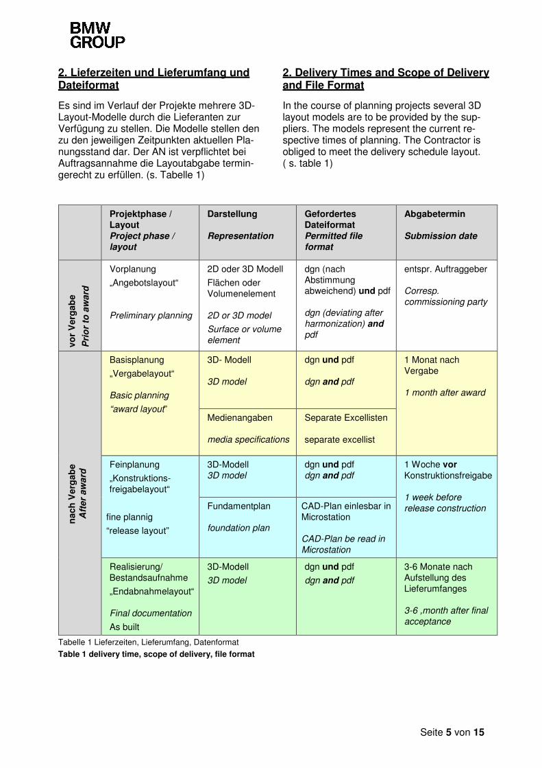
Es sind im Verlauf der Projekte mehrere 3D-Layout-Modelle durch die Lieferanten zur Verfügung zu stellen. Die Modelle stellen den zu den jeweiligen Zeitpunkten aktuellen Pla-nungsstand dar. Der AN ist verpflichtet bei Auftragsannahme die Layoutabgabe termin-gerecht zu erfüllen. (s. Tabelle 1)
In the course of planning projects several 3D layout models are to be provided by the sup-pliers. The models represent the current re-spective times of planning. The Contractor is obliged to meet the delivery schedule layout. ( s. table 1)
Projektphase / Layout Project phase /
layout
Darstellung Representation
Gefordertes Dateiformat Permitted file
format
Abgabetermin Submission date
vor
Ver
gab
e
Pri
or
to a
ward
Vorplanung
„Angebotslayout“ Preliminary planning
2D oder 3D Modell
Flächen oder Volumenelement 2D or 3D model
Surface or volume
element
dgn (nach Abstimmung abweichend) und pdf dgn (deviating after
harmonization) and
entspr. Auftraggeber Corresp.
commissioning party
nac
h V
erg
abe
Aft
er
aw
ard
Basisplanung
„Vergabelayout“ Basic planning
“award layout”
3D- Modell 3D model
dgn und pdf dgn and pdf
1 Monat nach Vergabe 1 month after award
Medienangaben media specifications
Separate Excellisten separate excellist
Feinplanung
„Konstruktions-freigabelayout“
3D-Modell 3D model
dgn und pdf dgn and pdf
1 Woche vor Konstruktionsfreigabe 1 week before
release construction fine plannig
“release layout”
Fundamentplan foundation plan
CAD-Plan einlesbar in Microstation CAD-Plan be read in
Microstation
Realisierung/ Bestandsaufnahme
„Endabnahmelayout“ Final documentation
As built
3D-Modell
3D model
dgn und pdf
dgn and pdf
3-6 Monate nach Aufstellung des Lieferumfanges 3-6 ,month after final
acceptance
Tabelle 1 Lieferzeiten, Lieferumfang, Datenformat
Table 1 delivery time, scope of delivery, file format
Seite 6 von 15
2.1 Änderungsmanagement 2.1 Change Management
Der AN hat bei layoutrelevanten Änderungen seines Planungsumfangs dem AG auch zwi-schen den Projektphasen (s. Tabelle 1) (DGN-Format + PDF) aktualisierte Daten zur Verfügung zu stellen.
In the case of layout-relevant modifications, the contractor must deliver the updated data to the purchaser between project phases (s. table 1) as well.
Layoutrelevante Änderungen sind: - Flächen-, Volumen- und Bauraumän-
derungen
- Änderungen an den Störkonturen - Änderungen an Medienanschluss-
punkten - Änderung der Position von Schalt-
schränken, Nebenaggregaten etc. - Unerwartete Erweiterungen der Anla-
gen
- Änderung von Transportrichtungen und Übergabepunkten
- etc.
layout-relevant modifications are: - change in area, volume and assembly
space
- change in interfering contours - change in place of media connection
- position change from control cabinets, auxiliary units etc.
- unexpacted extension of the system - change in transport direction and
transfer point
- etc.
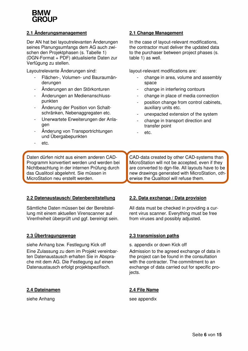
Daten dürfen nicht aus einem anderen CAD-Programm konvertiert werden und werden bei Nichtbeachtung in der internen Prüfung durch das Qualitool abgelehnt. Sie müssen in MicroStation neu erstellt werden.
CAD-data created by other CAD-systems than MicroStation will not be accepted, even if they are converted to dgn-file. All layouts have to be new drawings generated with MicroStation, oth-erwise the Qualitool will refuse them.
2.2 Datenaustausch/ Datenbereitstellung 2.2. Data exchange / Data provision
Sämtliche Daten müssen bei der Bereitstel-lung mit einem aktuellen Virenscanner auf Virenfreiheit überprüft und ggf. bereinigt sein.
All data must be checked in providing a cur-rent virus scanner. Everything must be free from viruses and possibly adjusted.
2.3 Übertragungswege 2.3 transmission paths
siehe Anhang bzw. Festlegung Kick off
Eine Zulassung zu dem im Projekt vereinbar-ten Datenaustausch erhalten Sie in Abspra-che mit dem AG. Die Festlegung auf einen Datenaustausch erfolgt projektspezifisch.
s. appendix or down Kick off
Admission to the agreed exchange of data in the project can be found in the consultation with the contracter. The commitment to an exchange of data carried out for specific pro-jects.
2.4 Dateinamen 2.4 File Name
siehe Anhang see appendix
Seite 7 von 15
2.5 Dateigröße 2.5 File Size
Als Orientierungshilfe bezüglich der Datei-größe dient die Mustermaschine. (siehe Ka-pitel 6.2)
The figuring machine is used as reference for file size. (see Chapter 6.2)
- maximale Dateigröße 2MB
- pro Anlage 500 KB Bei größeren Anlagen ist die Dateigröße mit dem CAD-Ansprechpartner des AG abzu-stimmen.
- max file size 2 MB
- per machine 500 KB For bigger systems talk to the customers CAD-contact.
Die Zeichnung muss datenbereinigt und komprimiert sein.
The drawing must be data-cleaned and zipped.
3. Planungssoftware 3. Planning Software
Basissoftware ist MicroStation von Bent-ley Systems.
Basic software is MicroStation developed by Bentley Systems.
Die Zusatzmodule der VenturisIT GmbH können ebenfalls benutzt werden. Die Nut-zung sollte mit dem CAD-Ansprechpartner des AG abgestimmt werden.
The add-ons from VenturisIT GmbH can be used, after consultation with customer’s CAD-contact.
ProjectWise ist die interne Datenbank des AG.
ProjectWise is the customer’s company-wide database.
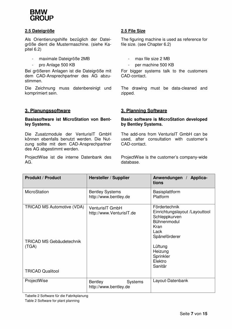
Produkt / Product Hersteller / Supplier Anwendungen / Applica-tions
MicroStation Bentley Systems http://www.bentley.de
Basisplattform Platform
TRICAD MS Automotive (VDA) TRICAD MS Gebäudetechnik (TGA) TRICAD Qualitool
VenturisIT GmbH http://www.VenturisIT.de
Fördertechnik Einrichtungslayout /Layouttool Schleppkurven Bühnenmodul Kran Lack Späneförderer Lüftung Heizung Sprinkler Elektro Sanitär
ProjectWise Bentley Systems http://www.bentley.de
Layout-Datenbank
Tabelle 2 Software für die Fabrikplanung Table 2 Software for plant planning
Seite 8 von 15
Daten für Druck-, Plot- und Viewmedien
Das Standardformat für alle Druck und Plot-ausgabedateien ist PDF (Maßstabsgetreu).
Data for print, plot and view media
The standard format for all print and plot out-put files is PDF (to scale).
Softwareversionen der Basissoftware und Applikationen Die Softwareversionen sind bei Auftrags-vergabe den b2b-Portalen (siehe Anhang) zu entnehmen und bei Änderungen während der Projektphase mit dem zuständigen CAD-Ansprechpartner des AG abzustimmen.
Software versions of the basic software and applications The software versions can be found in the B2B portals (see appendix) in procurement and vote on changes during the project phase to the competent CAD contact the AG.
4. Konfiguration und Einstellungen 4. Configuration and Settings
Siehe Anhang See appendix
5. Inhalte der zu liefernden 3D-Modelle 5. 3D Model Requirements
5.1 Zu liefernde 3D-Modelle 5.1 3D models to be supplied
Die 3D-Modelle müssen alle für die Lay-outplanung benötigten Informationen ent-halten. Die inhaltlichen Anforderungen rich-ten sich nach der jeweiligen Projektphase und sind den folgenden Abschnitten zu entnehmen.
The 3D models must include all the infor-mation needed for the layout planning. The substantive requirements are governed by the respective project phase and can be found in the following sections.
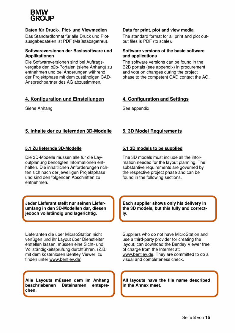
Jeder Lieferant stellt nur seinen Liefer-umfang in den 3D-Modellen dar, diesen jedoch vollständig und lagerichtig.
Each supplier shows only his delivery in the 3D models, but this fully and correct-ly.
Lieferanten die über MicrsoStation nicht verfügen und ihr Layout über Dienstleiter erstellen lassen, müssen eine Sicht- und Vollständigkeitsprüfung durchführen. (Z.B. mit dem kostenlosen Bentley Viewer, zu finden unter www.bentley.de)
Suppliers who do not have MicroStation and use a third-party provider for creating the layout, can download the Bentley Viewer free of charge from the Internet at: www.bentley.de. They are committed to do a visual and completeness check.
Alle Layouts müssen dem im Anhang beschriebenen Dateinamen entspre-chen.
All layouts have the file name described in the Annex meet.
Seite 9 von 15
5.2. Nicht zugelassene Funktionen 5.2 Non-Permitted MicroStation-Tools
- Weiterarbeiten in einer alten DGN Datei (Version der verwendeten MicroStation)
- Verschachtelte Zellen
- Ebenenkorrekturen - Digitale Signaturen und Zugriffss-
chutz
- Gespiegelte und skalierte Zellen - Aufgelöste Zellen/Geometrien
- Weiterverarbeiten eines Konzept-layouts
- Referenzen in Zeichnung kopieren
- .dwg-Datei in MicroStation als .dgn-Datei speichern
- Feature Elemente - Smart Solids - Doppelelemente
- Sprünge oder Lücken an zusam-mengesetzten Linien
- Flächen die nicht als Polygonfläche erstellt wurden
- Continue working on old DGN file (version of the used MicroStation)
- Interlaced cells
- Level overrides - Digital signatures and file protection
- Mirrored and scaled cells - Dissolved cells/geometries
- Work on concept layout
- Copy references in your drawing
- Save .dwg-files with MicroStation as .dgn-files
- Feature elements - Smart solids - Double element
- jumps or leaks with compound lines - Shapes that are not modeled as Pol-
ygon shapes
5.3 Angebotslayout 5.3 Preliminary planning layout
Das Angebotslayout dient dem AG als Abgleich zwischen dem zur Verfügung stehenden Planungsraumes und den maximalen Abmessungen des Lieferumfanges.
The offer layout serves as the AG balance between the available planning space and the maximum size of the delivery
Flächenüberschreitungen sind mit dem zuständigen Anlagen- und Layoutplaner abzustimmen.
Surface overruns are coordinated with the responsible system and layout planner.
Seite 10 von 15
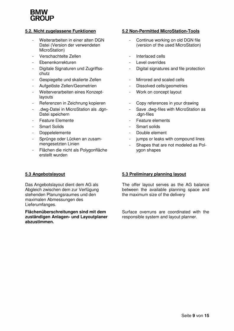
5.4 Vergabelayout 5.4 award layout
Beispiel: Schematische Darstellung einer Maschine in MicroStation (3D-CAD-Modell)
example: Schematic representation of a machine in MicroSta-tion (3D-CAD-Model)
Draufsicht mit Bauteillage und Transportrichtung
Top view with component location and the direction of transport
Das Vergabelayout wird vom Lieferanten nach der Beauftragung durch den AG gelie-fert. Inhaltliche Anforderungen:
The award layout shall be delivered by the suppliers after instruction by the commission-ing party. Content requirements:
- Werks-, Hallen- bzw. Liniennull-punkt (wird vom AG zur Verfügung gestellt)
- Maschinen-Nullpunkt Als Maschinen-Nullpunkt ist ein fixer Punkt der Maschine zu wählen, der nach Aufstellung der Maschine noch erkennbar ist.
- Geometrie und äußere Abmaße des Lieferumfanges incl. Vorhalt aller Ausbauräume, Öffnungswinkel und Sperrflächen
- Werkstücklage für Einlauf und Aus-lauf, Beschriftung von Einlauf und Auslauf
- Darstellung Art der Medienan-schlüsse: Kennzeichnung der An-schlüsse durch die Symbole aus der Zellbibliothek (siehe Anhang)
- Darstellung der Ausbaustufen (Re-serve) der Maschine/Anlage
- Kennzeichnung der Transportrich-tung (durch Pfeil in Transportrich-tung) (siehe Kapitel 6.3)
- Benennung der Arbeitsfolgen
- Plant (factory), hall or line zero point (made available by the commission-ing partner)
- Machine zero point The machine zero point is a fixed point at the machine which is still visi-ble after installation of the machine
- Geometry and external dimensions of the machine delivery, including deriv-ative all expansion spaces, opening angle and restricted areas.
- workpiece position for infeed and out-feed , labeling of infeed and outfeed.
- representation type of media connec-tions: Marking of connections through the symbols from the cell library (see appendix)
- representation of the expansion stag-es (reserve) of the machine / system
- Identification of the transport direction (indicated by arrow in the direction of transport) (see chapter 6.3)
- Naming AFO
Seite 11 von 15
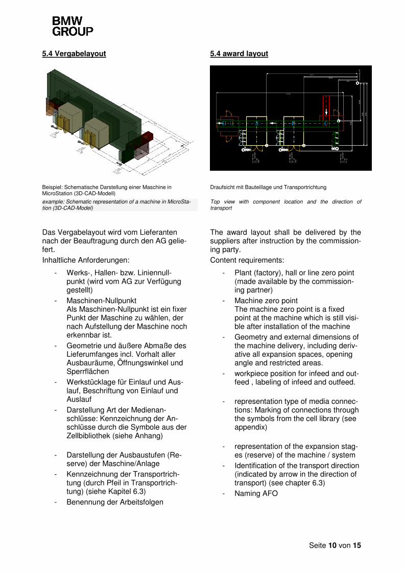
5.5 Konstruktionsfreigabelayout 5.5 Release layout
Beispiel: 3D-CAD-Modell einer Maschine in MicroStation
Example: 3D CAD model of a machine in MicroStation
Draufsicht eines Maschinenlayouts in MicroStation
Top view of a machine layout in MicroStation
Die Layoutfreigabe erfolgt durch den CAD-Ansprechpartner. Zusätzlich zu den Anforderungen aus Ab-schnitt 5.4 gelten folgende Anforderungen:
The layout Vetting by the CAD contact per-son. In addition to the requirements of section 5.4 the following requirements apply:
- Schnittstellen Werkstückübergabe-punkte, Darstellung der Werkstückla-ge Das Werkstück wird durch ein verein-fachtes 2D-Symbol in der jeweiligen Bearbeitungsposition dargestellt. Das Werkstück ist mehrfach darzustellen, wenn sich die Bearbeitungsposition verändert
- Die Verkettung ist mit allen Störkontu-ren, wie bspw. Motor, durch einfache Geometrien darzustellen
- Bemaßung des Maschinen-Nullpunkts zum Hallen-bzw. Linien-Nullpunkt in X- und Y-Richtung.
- Darstellung der Medienanschlüsse in original Höhe Modellieren der Anschluss-Stellen in 3D (Flansche, Rohrquerschnitte,...) Höhenangabe als Text
- Darstellung der Öffnungswinkel von Türen, Klappen und Zugängen; Kennzeichnung der Sperrflächen für Instandhaltung, Wartung und Bedie-nung; Kennzeichnung der Ausbau-räume.
- Darstellung von Einhausungen und Schutzzäunen
- Beschriftung: Jede Maschine ist mit AF-Nummer, Inv.-Nr., Hersteller und Maschinenart zu beschriften.
- Workpiece position for infeed and out-feed, labeling of infeed and outfeed The workpiece is represented by a simplified 2D symbol in the respective machining position. The workpiece is repeatedly display when changing the processing position.
- Linking width incl. supports, represen-tation of the engine by simple geome-try (cuboid)
- Connection dimensions: Distance ze-ro point - connection points to the ad-joining operation sequences or linking in the X- and Y-directions
- representation of the media connec-tions in the original hight, modeling of interchanges in 3D ( flanges, pipe di-ameters, ...) Altitude as text
- representation of the opening angle of doors, hatches and entrances ; Identification of restricted areas for upkeep, maintenance and operation ; Marking the expansion spaces.
- representation of enclosures and protective fences
- labelling: Each machine must be la-beled with the AF-Number, inventory no, manufacturer, and machine type.
Seite 12 von 15
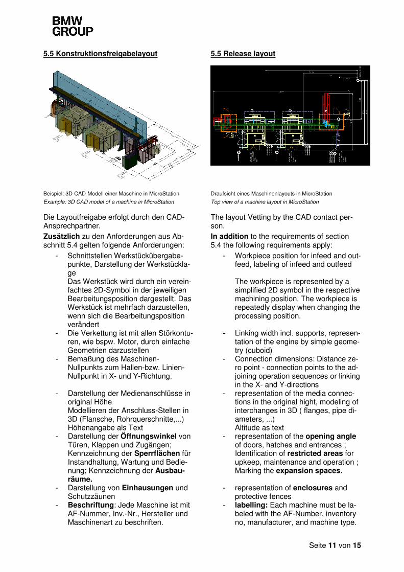
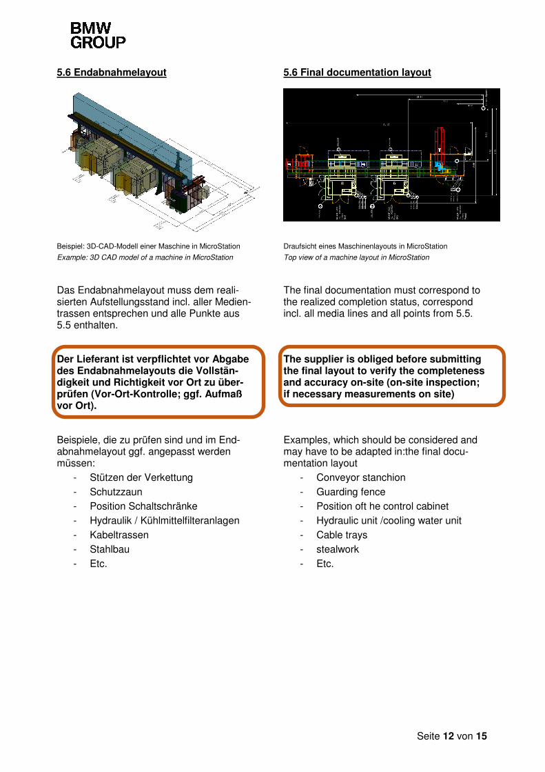
5.6 Endabnahmelayout 5.6 Final documentation layout
Beispiel: 3D-CAD-Modell einer Maschine in MicroStation
Example: 3D CAD model of a machine in MicroStation
Draufsicht eines Maschinenlayouts in MicroStation
Top view of a machine layout in MicroStation
Das Endabnahmelayout muss dem reali-sierten Aufstellungsstand incl. aller Medien-trassen entsprechen und alle Punkte aus 5.5 enthalten.
The final documentation must correspond to the realized completion status, correspond incl. all media lines and all points from 5.5.
Der Lieferant ist verpflichtet vor Abgabe des Endabnahmelayouts die Vollstän-digkeit und Richtigkeit vor Ort zu über-prüfen (Vor-Ort-Kontrolle; ggf. Aufmaß vor Ort).
The supplier is obliged before submitting the final layout to verify the completeness and accuracy on-site (on-site inspection; if necessary measurements on site)
Beispiele, die zu prüfen sind und im End-abnahmelayout ggf. angepasst werden müssen:
- Stützen der Verkettung
- Schutzzaun - Position Schaltschränke - Hydraulik / Kühlmittelfilteranlagen
- Kabeltrassen - Stahlbau
- Etc.
Examples, which should be considered and may have to be adapted in:the final docu-mentation layout
- Conveyor stanchion
- Guarding fence - Position oft he control cabinet - Hydraulic unit /cooling water unit
- Cable trays - stealwork
- Etc.
Seite 13 von 15
6. Mitgeltende / weiterführende Unter-lagen
6. Other applicable / other relevant doc-uments
6.1 Anhänge 6.1 Appendix
Einstellungen und weiterführende Informa-tionen finden sie im Anhang.
Please find settings and further information at the appendix.
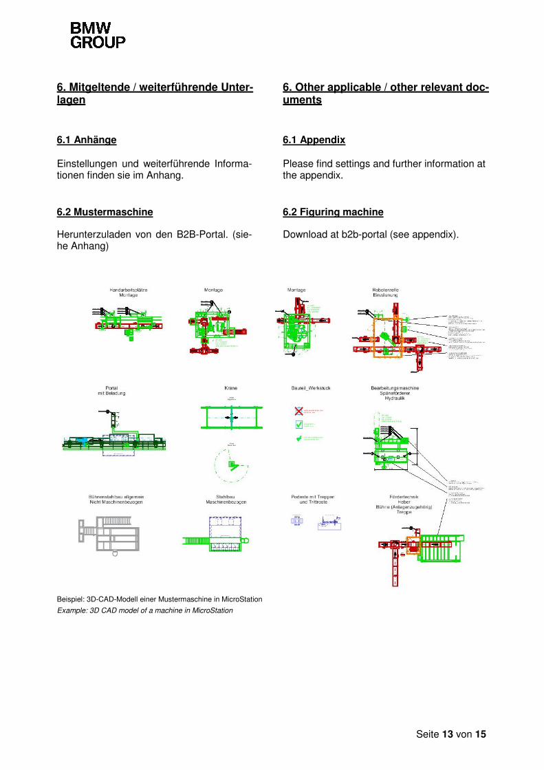
6.2 Mustermaschine 6.2 Figuring machine
Herunterzuladen von den B2B-Portal. (sie-he Anhang)
Download at b2b-portal (see appendix).
Beispiel: 3D-CAD-Modell einer Mustermaschine in MicroStation
Example: 3D CAD model of a machine in MicroStation
Seite 14 von 15
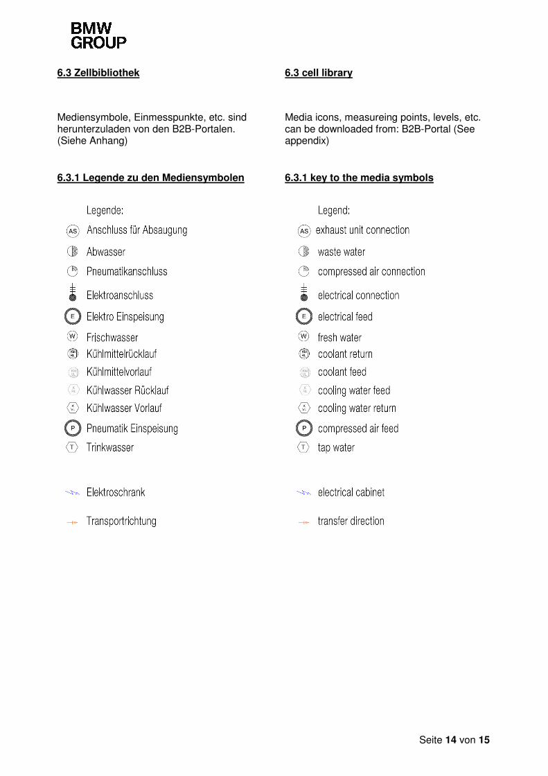
6.3 Zellbibliothek 6.3 cell library
Mediensymbole, Einmesspunkte, etc. sind herunterzuladen von den B2B-Portalen. (Siehe Anhang)
Media icons, measureing points, levels, etc. can be downloaded from: B2B-Portal (See appendix)
6.3.1 Legende zu den Mediensymbolen 6.3.1 key to the media symbols
Seite 15 von 15
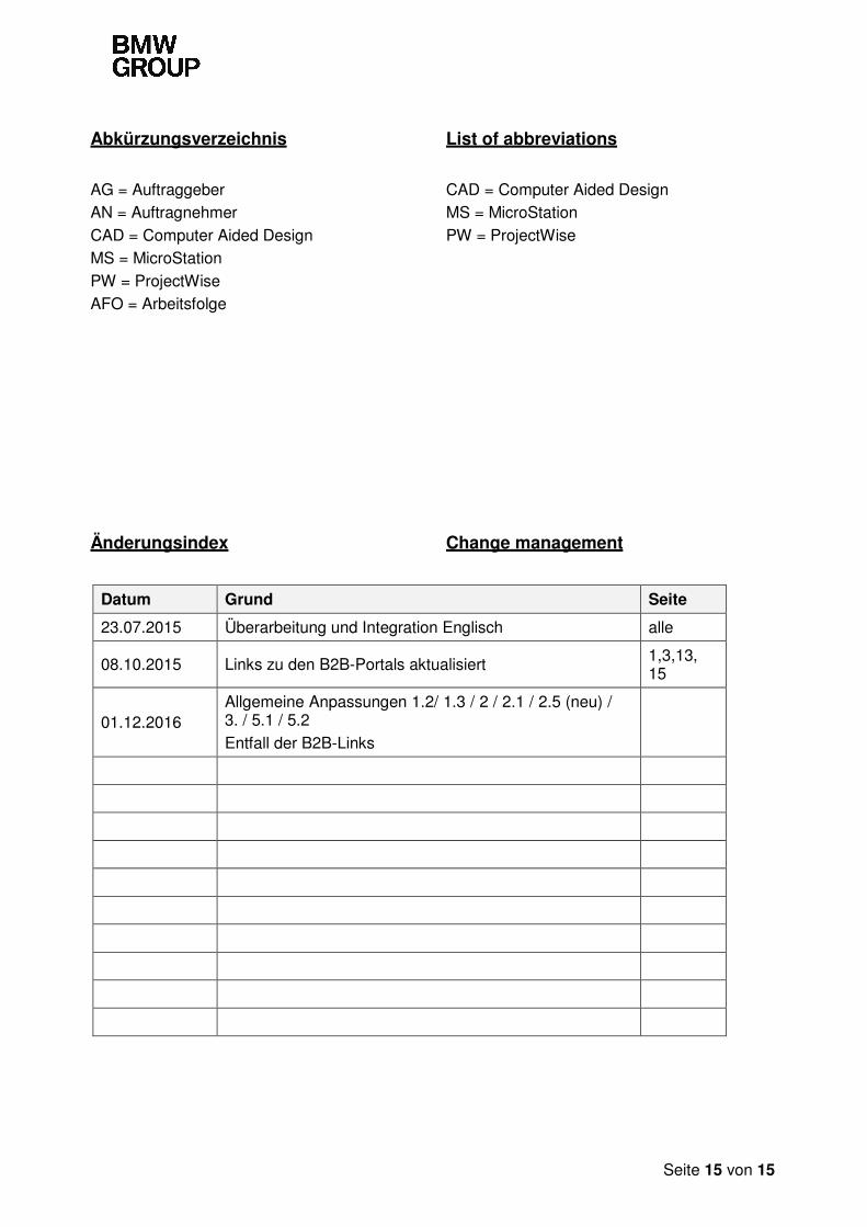
Abkürzungsverzeichnis
AG = Auftraggeber AN = Auftragnehmer
CAD = Computer Aided Design MS = MicroStation
PW = ProjectWise AFO = Arbeitsfolge
List of abbreviations
CAD = Computer Aided Design MS = MicroStation
PW = ProjectWise
Änderungsindex Change management
Datum Grund Seite
23.07.2015 Überarbeitung und Integration Englisch alle
08.10.2015 Links zu den B2B-Portals aktualisiert 1,3,13, 15
01.12.2016 Allgemeine Anpassungen 1.2/ 1.3 / 2 / 2.1 / 2.5 (neu) / 3. / 5.1 / 5.2
Entfall der B2B-Links