Lashed Aerial Installation of Fiber Optic Cable | HARDWARE | TOOL
27
P/N 005-010 Issue 13 Standard Recommended Procedure 005-010 | Issue 13 | April 2017 | Page 1 of 27 Lashed Aerial Installation of Fiber Optic Cable Table of Contents 1. Precautions 2 2. Planning and Preparation 5 Planning Issues ........................................................................................... 5 Poles and Authorization................................................................................... 5 Rights-of-Way............................................................................................. 6 Installation Issues ........................................................................................ 6 Splice Locations ........................................................................................... 6 Materials Requirements................................................................................... 6 3. Lashed Aerial Plant - An Overview 6 Suspension Strands (Messenger Wires) .................................................................... 7 Overlashing ............................................................................................... 8 Bonding and Grounding................................................................................... 8 Pulling Grips .............................................................................................. 9 Drip Loops ................................................................................................ 9 Lashers 10 Lasher Operation......................................................................................... 11 Transferring Lashers Around Poles ........................................................................ 12 Deadends and Crossovers ................................................................................ 13 Splicing and Slack Storage ................................................................................ 13 Packaging Removal ...................................................................................... 14 Storing Partial Cable Reels. . . . . . . . . . . . . . . . . . . . . . . . . . . . . . . . . . . . . . . . . . . . . . . . . . . . . . . . . . . . . . . . . . . . . . . . . . . . . . . . 14 4. Installation Methods- Equipment Requirements 14 5. Moving Reel (Drive-Off) Method 15 6. Stationary Reel (Back-Pull) Method 18 Cable Reel Placement .................................................................................... 18 Cable Pullers ............................................................................................. 19 7. Strand Preparation 19 Cable Blocks ............................................................................................. 19 Corner Equipment ....................................................................................... 21 Back-Pulling by Hand. . . . . . . . . . . . . . . . . . . . . . . . . . . . . . . . . . . . . . . . . . . . . . . . . . . . . . . . . . . . . . . . . . . . . . . . . . . . . . . . . . . . . 21 Winch-Assisted Pulls ..................................................................................... 22 Back-pull Lashing ........................................................................................ 24 8. Combination Methods 25 9. Post-Construction Inspection 27
Transcript of Lashed Aerial Installation of Fiber Optic Cable | HARDWARE | TOOL

P/N 005-010Issue 13
Standard Recommended Procedure 005-010 | Issue 13 | April 2017 | Page 1 of 27
Lashed Aerial Installation of Fiber Optic Cable
Table of Contents1. Precautions . . . . . . . . . . . . . . . . . . . . . . . . . . . . . . . . . . . . . . . . . . . . . . . . . . . . . . . . . . . . . . . . . . . . . . . . . . . . . . . . . . . . . . . . . . . . . . 22. Planning and Preparation . . . . . . . . . . . . . . . . . . . . . . . . . . . . . . . . . . . . . . . . . . . . . . . . . . . . . . . . . . . . . . . . . . . . . . . . . . . . . . . . . .5
Planning Issues . . . . . . . . . . . . . . . . . . . . . . . . . . . . . . . . . . . . . . . . . . . . . . . . . . . . . . . . . . . . . . . . . . . . . . . . . . . . . . . . . . . . . . . . . . . 5Poles and Authorization . . . . . . . . . . . . . . . . . . . . . . . . . . . . . . . . . . . . . . . . . . . . . . . . . . . . . . . . . . . . . . . . . . . . . . . . . . . . . . . . . . . 5Rights-of-Way . . . . . . . . . . . . . . . . . . . . . . . . . . . . . . . . . . . . . . . . . . . . . . . . . . . . . . . . . . . . . . . . . . . . . . . . . . . . . . . . . . . . . . . . . . . . .6Installation Issues . . . . . . . . . . . . . . . . . . . . . . . . . . . . . . . . . . . . . . . . . . . . . . . . . . . . . . . . . . . . . . . . . . . . . . . . . . . . . . . . . . . . . . . .6Splice Locations . . . . . . . . . . . . . . . . . . . . . . . . . . . . . . . . . . . . . . . . . . . . . . . . . . . . . . . . . . . . . . . . . . . . . . . . . . . . . . . . . . . . . . . . . . .6Materials Requirements . . . . . . . . . . . . . . . . . . . . . . . . . . . . . . . . . . . . . . . . . . . . . . . . . . . . . . . . . . . . . . . . . . . . . . . . . . . . . . . . . . .6
3. Lashed Aerial Plant - An Overview . . . . . . . . . . . . . . . . . . . . . . . . . . . . . . . . . . . . . . . . . . . . . . . . . . . . . . . . . . . . . . . . . . . . . . . . . . 6Suspension Strands (Messenger Wires) . . . . . . . . . . . . . . . . . . . . . . . . . . . . . . . . . . . . . . . . . . . . . . . . . . . . . . . . . . . . . . . . . . . . 7Overlashing . . . . . . . . . . . . . . . . . . . . . . . . . . . . . . . . . . . . . . . . . . . . . . . . . . . . . . . . . . . . . . . . . . . . . . . . . . . . . . . . . . . . . . . . . . . . . . .8Bonding and Grounding . . . . . . . . . . . . . . . . . . . . . . . . . . . . . . . . . . . . . . . . . . . . . . . . . . . . . . . . . . . . . . . . . . . . . . . . . . . . . . . . . . .8Pulling Grips . . . . . . . . . . . . . . . . . . . . . . . . . . . . . . . . . . . . . . . . . . . . . . . . . . . . . . . . . . . . . . . . . . . . . . . . . . . . . . . . . . . . . . . . . . . . . .9Drip Loops . . . . . . . . . . . . . . . . . . . . . . . . . . . . . . . . . . . . . . . . . . . . . . . . . . . . . . . . . . . . . . . . . . . . . . . . . . . . . . . . . . . . . . . . . . . . . . . .9Lashers 10Lasher Operation . . . . . . . . . . . . . . . . . . . . . . . . . . . . . . . . . . . . . . . . . . . . . . . . . . . . . . . . . . . . . . . . . . . . . . . . . . . . . . . . . . . . . . . . . 11Transferring Lashers Around Poles . . . . . . . . . . . . . . . . . . . . . . . . . . . . . . . . . . . . . . . . . . . . . . . . . . . . . . . . . . . . . . . . . . . . . . . . 12Deadends and Crossovers . . . . . . . . . . . . . . . . . . . . . . . . . . . . . . . . . . . . . . . . . . . . . . . . . . . . . . . . . . . . . . . . . . . . . . . . . . . . . . . . 13Splicing and Slack Storage . . . . . . . . . . . . . . . . . . . . . . . . . . . . . . . . . . . . . . . . . . . . . . . . . . . . . . . . . . . . . . . . . . . . . . . . . . . . . . . . 13Packaging Removal . . . . . . . . . . . . . . . . . . . . . . . . . . . . . . . . . . . . . . . . . . . . . . . . . . . . . . . . . . . . . . . . . . . . . . . . . . . . . . . . . . . . . . 14Storing Partial Cable Reels. . . . . . . . . . . . . . . . . . . . . . . . . . . . . . . . . . . . . . . . . . . . . . . . . . . . . . . . . . . . . . . . . . . . . . . . . . . . . . . . 14
4. Installation Methods- Equipment Requirements . . . . . . . . . . . . . . . . . . . . . . . . . . . . . . . . . . . . . . . . . . . . . . . . . . . . . . . . . . . .145. Moving Reel (Drive-Off) Method . . . . . . . . . . . . . . . . . . . . . . . . . . . . . . . . . . . . . . . . . . . . . . . . . . . . . . . . . . . . . . . . . . . . . . . . . . .156. Stationary Reel (Back-Pull) Method . . . . . . . . . . . . . . . . . . . . . . . . . . . . . . . . . . . . . . . . . . . . . . . . . . . . . . . . . . . . . . . . . . . . . . . . .18
Cable Reel Placement . . . . . . . . . . . . . . . . . . . . . . . . . . . . . . . . . . . . . . . . . . . . . . . . . . . . . . . . . . . . . . . . . . . . . . . . . . . . . . . . . . . . 18Cable Pullers . . . . . . . . . . . . . . . . . . . . . . . . . . . . . . . . . . . . . . . . . . . . . . . . . . . . . . . . . . . . . . . . . . . . . . . . . . . . . . . . . . . . . . . . . . . . . 19
7. Strand Preparation . . . . . . . . . . . . . . . . . . . . . . . . . . . . . . . . . . . . . . . . . . . . . . . . . . . . . . . . . . . . . . . . . . . . . . . . . . . . . . . . . . . . . . 19Cable Blocks . . . . . . . . . . . . . . . . . . . . . . . . . . . . . . . . . . . . . . . . . . . . . . . . . . . . . . . . . . . . . . . . . . . . . . . . . . . . . . . . . . . . . . . . . . . . . 19Corner Equipment . . . . . . . . . . . . . . . . . . . . . . . . . . . . . . . . . . . . . . . . . . . . . . . . . . . . . . . . . . . . . . . . . . . . . . . . . . . . . . . . . . . . . . . 21Back-Pulling by Hand. . . . . . . . . . . . . . . . . . . . . . . . . . . . . . . . . . . . . . . . . . . . . . . . . . . . . . . . . . . . . . . . . . . . . . . . . . . . . . . . . . . . . 21Winch-Assisted Pulls . . . . . . . . . . . . . . . . . . . . . . . . . . . . . . . . . . . . . . . . . . . . . . . . . . . . . . . . . . . . . . . . . . . . . . . . . . . . . . . . . . . . .22Back-pull Lashing . . . . . . . . . . . . . . . . . . . . . . . . . . . . . . . . . . . . . . . . . . . . . . . . . . . . . . . . . . . . . . . . . . . . . . . . . . . . . . . . . . . . . . . .24
8. Combination Methods . . . . . . . . . . . . . . . . . . . . . . . . . . . . . . . . . . . . . . . . . . . . . . . . . . . . . . . . . . . . . . . . . . . . . . . . . . . . . . . . . . . 259. Post-Construction Inspection . . . . . . . . . . . . . . . . . . . . . . . . . . . . . . . . . . . . . . . . . . . . . . . . . . . . . . . . . . . . . . . . . . . . . . . . . . . . . 27

Standard Recommended Procedure 005-010 | Issue 13 | April 2017 | Page 2 of 27
1. Precautions
1.1 General Safety PrecautionsWARNING: To reduce the chance of accidental injury:
a. All personnel involved in the aerial installation must be thoroughly familiar with the operation of the equipment and construction apparatus being used.
b. Inspect all equipment (ladders, bucket trucks, reel trailers, etc.) for defects and replace if found in unsound condition.
c. Use only company-approved equipment for lighting, heating, and other operations.d. Arrange or secure any material in a bucket truck or on a ladder so that it cannot
fall. Materials and equipment should not unnecessarily impede pedestrian or vehicular traffic.
e. Allocate the appropriate number and type of safety personnel and equipment called for in your company’s safety procedures. Such personnel and equipment may include:
• Flagmen
• Pilot vehicles
• Roadside barricades, warning signs, traffic cones, beacon lights, etc.
• ABC-rated fire extinguishers on board all company vehicles.
1.2 Occupational Precautions
1.3 Laser Precautions
CAUTION: Before starting any aerial cable installation, all personnel must be thoroughly familiar with all applicable Occupational Safety and Health Act (OSHA) regulations, the National Electrical Safety Code (NESC), state and local regulations, and company safety practices and policies. Failure to do so can result in life-threatening injury to employees or the general public.
WARNING: To reduce the chance of accidental injury:
a. Use protective leather gloves and, if necessary, lineman’s rubber gloves. Use the leather gloves when climbing or descending a pole, and when working with sharp instruments or materials. Wear rubber gloves when working near exposed electrical circuits.
b. Use a safety harness on all bucket trucks and aerial lifts. A body belt and safety strap for the bucket or platform must be used when the equipment is in operation to minimize the chance of injury.
c. Before climbing a pole, inspect it for significant deterioration and safety hazards (splintering, insect nests, sharp protrusions, etc.).
d. Position all motorized equipment so that exhausts are directed away from the location where most work will be done.
e. Personnel normally should not remain in an area where a cable is being pulled around a piece of hardware under tension. A craftsman can remain in such an area (for example, to observe the alignment of a cable around a corner block), if he or she stays clear of the hardware under tension and has a clear path to safety.
f. Keep hands free of tools or materials when climbing or descending a pole or ladder. Do not step on cables, cable enclosures, or suspended equipment which might provide unsafe footholds.
g. Always lower cable blocks and other equipment from strand level with a handline.
WARNING: Never look directly into the end of a fiber that may be carrying laser light . Laser light can be invisible and can damage your eyes. Viewing it directly does not cause pain. The iris of the eye will not close involuntarily as when viewing a bright light. Consequently, serious damage to the retina of the eye is possible. Should accidental eye exposure to laser light be suspected, arrange for an eye examination immediately.

Standard Recommended Procedure 005-010 | Issue 13 | April 2017 | Page 3 of 27
1 .4 . Cable Handling Precautions
The following applies to all fiber count gel-free and gel-filled armor ribbon cables installed in aerial plant, including down pole pedestal turn-ups:When jacket opening is made for a splice closure, pedestal, terminal cut-in, or for any other reason that requires jacket and armor removal, the following must be performed:
• Allow sufficient slack for coils on both sides of closure or other access point for five cable loops compliant with or larger than the minimum bend radius (MBR) – Operating. The MBR (Operating) is 10 times Outside Diameter (OD) of the cable. MBR and OD are listed on the cable specification sheet located on Corning’s public web site: http://catalog.corning.com/opcomm/en-US/catalog/CategoryBrowser.aspx?cid=fiber_optic_cables_web&rot=fiber_optic_cables_web&root=products
• The cable loops (five), formed on each side of the closure or access point where a jacket opening is being made or planned to be made, are in addition to the cable length required for fiber ribbon splicing and routing in the closure. In the product specification or installation procedure, check the length required for the particular closure or other access point hardware that will be used.
• Follow the mid-span coiling procedure found in SRP 004-086 to make mid-span coils: http://csmedia.corning.com/opcomm/Resource_Documents/SRPs_rl/004-086.pdf
• Coils are required for all ribbon gel-free and gel-filled armor cables that are in a butt-type closure any other closure, or access point hardware.
• Using snowshoes that are compliant with or larger than the MBR - Operating can be used, provided that a total of five loops are made.
• Pedestal turn-ups require loops at the aerial down-turn, typically no greater than 20 feet from the pedestal — at the pole messenter dead end.
• DO NOT introduce twists into the coil• Coils are required whenever there is a dead-ended cable that is left for future
splicing. Cable length for both coils and splicing must be planned for and allocated.• When cable is engineered, include sufficient lengths for coils at all jacket entry
locations, and indicated on work prints.1 .5 . The following may be used as a general guideline for maximum pulling tension for standard, non-connectorized Corning Optical Communications outdoor fiber optic cable: 600 lbF (2,700 N)
1 .6 . Corning Optical Communications cable specification sheets also list the minimum cable bend radius both “Loaded” (during installation) and “ Installed” (after installation). If these sheets are not available on the job-site, the following formulas may be used to determine general guidelines for installing Corning Optical Communications fiber optic cable:
CAUTION: Fiber optic cable is sensitive to excessive pulling, bending, and crushing forces. Consult the cable specification sheet for the cable you are installing. Do not bend the cable more sharply than the minimum recommended bend radius. Do not apply more pulling force to the cable than specified. Do not crush the cable or allow it to kink. Doing so may cause damage that can alter the transmission characteristics of the cable; the cable may have to be replaced.

Standard Recommended Procedure 005-010 | Issue 13 | April 2017 | Page 4 of 27
To arrive at an operating minimum bend radius for cable installation, multiply 15 times (15 x) the cable outside diameter. Example:
Cable Diameter = 0.46 in (11.8 mm)
15 x 0.46 in = 6.9 in (177 mm)
Minimum Bend Radius (Operating) = 6.9 in (17.7 cm)
To find the minimum diameter requirement for pull wheels or rollers, simply double the minimum bend radius (Operating):
1 .7 . All pulling equipment and hardware that will contact the cable during installation must maintain the minimum bend radius of the fiber optic cable as listed.
1 .8 . Situations which require the use of radius-maintaining devices include the following:• when cable is placed on blocks, sheaves, or quadrant blocks.• at all bends of the cable route.
NOTE: Carefully select hardware that maintains cable bend radius. Not all equipment is well suited for fiber optic cable installation. Consult your company’s standard operating procedures for details.
1 .9 . Exercise care to prevent damage to cables while setting up equipment or while using tools of any kind. Be extremely careful when handling cable reels or loading reels on trailers or vehicles.
1 .10 . Leave cable reel packaging on the cable reels until they arrive at the cable site. If the packaging has been previously removed, securely fasten the cable end(s) to avoid damage during transit. If the cable ends are not secured, vehicle bouncing can cause the cable to loosen on the reel, resulting in kinks, irregular cable bundles, or crosswraps.
1 .11 . Establish good communications between the pull, feed, and monitoring locations before starting any installation. This is especially critical when a winch is used to pull the cable.
1 .12 . Avoid surges and jerks of the reel at all times. Properly adjusted reel brakes should be used in all installations.
1 .13 . To prevent damage to the cable and ensure lowest possible tensile load (drag), cable reels should be attended while the cable is being pulled.
1 .14 . If the cable must be unreeled during installation, use the figure-eight configuration to prevent kinking or twisting. Fiber optic cable should not be coiled in a continuous direction except for lengths of 100 ft (30 m) or less. The preferred size of the “figure-eight” is about 15 ft (4.5 m) in length, with each loop about 5 ft (1.5 m) to 8 ft (2.4 m) in diameter. Traffic cones spaced 7 - 8 feet apart are useful as guides during “figure-eighting.”
NOTE: When “figure-eighting” long lengths of cable, take steps to relieve pressure on the cable at the crossover of the eight. This can be done by placing cardboard shims at the crossover, or by forming a second “figure-eight.” If the “figure-eight” must be flipped over to obtain the pulling eye, it can be easily accomplished by three men, one at each end and one in the center. The cable can then be pulled off the “figure-eight” the remaining distance.
Cable
Bendradius
TPA-3104
(1.5 m) 8 ft
25 ft
(7.62 M)
15 ft
(4.
5 m
)
Cardboardshims
TPA-3105
WARNING: It has been experimentally determined that the use of “figure-eight” machines will damage Corning Optical Communications double-armored SST designs. The use of this equipment on these cables is not recommended. Other similar cable designs may also be affected. Before using such a machine, contact the machine manufacturer for their recommendation on the suitability of their machine to the cable design being installed.
2 x 6.9 in =
13.8 in (35.4 cm)

Standard Recommended Procedure 005-010 | Issue 13 | April 2017 | Page 5 of 27
1 .15 . DO NOT CUT THE CABLE UNDER ANY CIRCUMSTANCES without consulting the outside plant engineer on the job. Splice points for fiber optic cable are specifically designed into the route. Additional splice points must be approved by the construction supervisor prior to cutting the cable.
1 .16 . Take precautions to protect reeled cable from vandals or other sources of possible damage while unattended. The sections of cable intended for aerial installation are often produced to meet specific length requirements. Any damage to the cable sections may require replacement of the entire section.
1 .17 . If the cable is laid on the pavement/ground during installation, provide barricades or other means of preventing vehicular or pedestrian traffic in the area.
1 .18 . Do not increase the tension in a strand to which a fiber optic cable is already lashed.
1 .19 . At the completion of a day’s installation, protect bare cable ends by placing a cable cap on the end of the cable, followed by several wraps of tape around each cap. This will assist the moisture-resisting material in Corning Optical Communications loose-tube cable in preventing water ingress due to long-term exposure to moisture. If a cap is not available, a few wraps of tape placed on the tip of the cable should prevent water from entering the cable.
NOTE: If the cable ends are not capped while exposed to the environment for long periods of time, the customer may choose (but is not required) to cut off one meter of each cable end before splicing. This will ensure that no moisture ingress is present.
1 .20 . Corning Optical Communications recommends the use of fiber optic cable warning signs for identification of the fiber optic plant. Reference your company’s standard procedures for marking cable plant.
2. Planning and Preparation2 .1 . Before beginning an aerial installation, the cable route must be surveyed jointly by engineering and construction personnel. The route survey will determine the installation method to be used, as well as equipment and material requirements. Representatives from each agency having jurisdiction over items such as traffic lights and overpasses should be present during the route survey. Identify potential problems with cable placement at this time.
Planning Issues2 .2 . Examine and resolve the following issues during the planning stage in order to achieve a smooth installation of aerial plant.
Poles and Authorization2 .3 . Determine the ability of existing pole lines and guys to support the new cable plant, as well as any restrictions imposed by the pole owner. The anchoring and guying of the cable plant is crucial for its safe operation. Ideally, the guying should remove all of the lateral stress on each pole so that the pole simply supports the weight of the cables, hardware and equipment attached to it. Follow your company’s normal specifications concerning anchoring and guying of poles for copper plant.
2 .4 . Set new poles only when there is no existing utility line and when a reasonable alternate route does not exist. Explore alternate approaches such as under-ground trenching before making the decision to place new poles. Written permission must be obtained from the proper authorities before placing new poles, and all other utilities having underground plant in the area must be contacted so they can locate and mark their facilities prior to new pole placement. Keep copies of this written permission on-site as the pole-line is constructed.
2 .5 . Be certain to ensure proper clearance from electric power lines and other cables that may sag near the fiber optic cable. Determine the clearances between the proposed fiber optic cable plant and existing facilities on a case-by-case basis by referring to the National Electrical Safety Code (NESC) and appropriate local safety codes.

Standard Recommended Procedure 005-010 | Issue 13 | April 2017 | Page 6 of 27
WARNING: Not withstanding the fact that NESC spacing is observed, there is still a danger of flashover (sparking) from a power line to the metallic messenger which may cause electrocution to installers of the cable. Hold a safety meeting between all involved parties to discuss a plan of action concerning the proper clearances required to ensure a safe outside plant installation.
2 .6 . Verify messenger wire assignments. Because Corning Optical Communications fiber optic cable is light in weight and its sag in aerial span small, it should occupy the uppermost available communication space on the pole. Installation of aerial fiber optic cable routes on joint-use pole lines is possible if sufficient space is available to provide the required vertical clearance.
Rights-of-Way2 .7 . Obtain the proper right-of-way clearances. Be certain this right-of-way is free of obstacles such as guy wires, trees, etc. Determine if the reel-carrying vehicle can be operated close to the cable route.Never set up equipment on private property without obtaining prior permission from the property owner.
Installation Issues 2 .8 . Determine any special installation issues, such as railways, highways, and waterways. Outline procedures to contend with these issues.
2 .9 . Develop a schedule for outside plant activities. Ensure coordination of this schedule with other project schedules (central office equipment, etc.). Prepare work orders for the new construction, maintenance, and rearrangements needed along the route.
Splice Locations2 .10 . Select splice locations during the survey and make plans for closure and cable slack storage. Corning Optical Communications recommends that at splice points, installation crews leave enough cable slack on each cable end to reach the ground and into a splice vehicle, plus 16 ft (5 m). This cable slack must be taken into account when ordering cable lengths.
Consider the accessibility of these splicing locations by splicing vehicles. These locations should not fall in sites where access is inconvenient or hazardous.The preliminary choice of splice locations during the route survey allows verification of the transmission design and provides the basis for cable order lengths.2 .11 . Develop a feasible placement plan for each reel of cable. Inspect the pull-off locations for suitability.
2 .12 . Planning must consider installation techniques such as back-pull (stationary reel) versus drive-off (moving reel), pulling two cables at once, single versus double lashing, overlashing, etc.
Materials Requirements2 .13 . Determine quantities of cable and other materials which must be ordered. Tree trimming may be required to verify route suitability and accurate cable length. Special requirements for sequencing the cable shipments must be specified in the cable order.
3. Lashed Aerial Plant - An Overview3 .1 . This section provides a general overview of lashed aerial plant. The elements of aerial plant discussed in this section are common to lashed aerial plant, regardless of the installation method used:
• Suspension strands (messenger wires)• Overlashing• Bonding and grounding• Pulling grips
16 ft (5 m)of additional slack
TPA-3187

Standard Recommended Procedure 005-010 | Issue 13 | April 2017 | Page 7 of 27
• Drip loops• Lashers
• Lasher operation• Transferring lashers around poles
• Deadends and crossovers• Splicing and slack storage• Storing partial cable reels
Suspension Strands (Messenger Wires)3 .2 . Record the cable distance marks at approximately every other pole location and at each cable end on the construction prints for emergency restoration and maintenance purposes.3 .3 . Suspension strands used in telephony are classified by rated breaking strength and the type of steel used in their construction. Seven of the more common sizes are listed. The “UG” (Utilities Grade) or “EHS” (Extra High Strength Grade), indicates the tensile strength of the steel used in the messenger.
3 .4 . For general applications, Table 3 shows the minimum stringing tensions for a particular cable weight category using different messenger grades. The messenger tensions listed are the minimum tensions required for each span to reduce cable strain to an acceptable level.
NOTE: Both tables 2 and 3 are based on the following assumptions: 1) use of a dedicated messenger (no overlashing); 2) heavy loading conditions; 3) 59°F (15°C) initial stringing temperature; 4) reasonably level terrain.CAUTION: Caution: Suspension strands are susceptible to fatigue failure near pole-mounted suspension clamps if left under critical stringing tensions without supporting a load. Because all standard Corning Optical Communications fiber optic cables weigh less than 0.4 pounds per foot, the strand is effectively under no load. Consult the strand manufacturer to determine the critical tension for the strand used in your installation. Often, by increasing the messenger size by one or two categories or by using vibration dampening weights on the span, the problem of fatigue failure can be avoided.
3 .5 . Given the variables involved messenger type and outside diameter (OD), cable weight and OD, loading conditions, span length, etc.) Corning Optical Communications can calculate the cable’s sag and strain for specific aerial installations. Recommended tensions and messenger types can also be generated for these applications. Please contact Corning Optical Communications Engineering Services at 1-800-743-2671 for minimum recommended messenger tensions, as well as the resulting sag for specific applications.
3 .6 . Please note that when a suspension strand is specified for a fiber optic cable, the most important considerations are that the strand is strong enough, and that excess cable strain does not occur. When the diameter of a strand is enlarged to increase its strength, its weight and the effect of wind and ice loading is affected, which increases cable strain. Normally the “best” strand is not the question, but rather if the normal strand is satisfactory. Technically, the smallest EHS messenger with a satisfactory strength is “best.”
Diameter (in inches) Grade Rating (lbs)
Table 2: Cable Sizes, Grades and Ratings
TPA-3188
1/4
5/16
5/16
3/8
3/8
7/16
1/2
EHS
UG
EHS
UG
EHS
UG
UG
6600
6000
11200
10000
16000
16000
25000
Table 3: Minimum and Critical Messenger Tensions in Pounds Prior to Aerial Installation of Corning Cable
Systems Fiber Optic Cable
Maximum 0.18 lb/ft, 0.80 Inches Diameter Cable, (Using EHS Messenger, Not UG)
Span (feet)
Messenger Up to 200 200-300 300-400 Critical Tension*
1/4 in (6.6M EHS) 1200 1600 – 2000
5/16 in (11.2M EHS) 1500 1800 2400 3000
3/8 in (16M EHS) 1800 2200 2600 6000
Maximum 0.16 lb/ft, 0.68 Inches Diameter Cable, (Using UG Messenger, Not EHS)
Span (feet)
Messenger Up to 200 200-300 300-400
5/16 in (6M UG) 1600 – – –
3/8 in (10M UG) 1800 2200 2500 –
* Critical tensions and strand fatigue failures
TPA-3189

Standard Recommended Procedure 005-010 | Issue 13 | April 2017 | Page 8 of 27
3 .7 . When installing a dedicated suspension strand for fiber optic cable, standard hardware (eyebolts, clamps, etc.) should be used. Your company’s normal messenger wire installation procedures (pole framing, hardware placement, etc.) should be used.
3 .8 . The final “slack-span,” which is the span from the last pole outside a building to the building itself, is the only span which may be tensioned at lower than the critical value. Standard hardware for copper plant should be used to support this “slack-span.” Crew members should pay close attention to ensure that the minimum bend radius of the cable is not exceeded. If possible, the cable should enter the building through an existing entrance point.
Overlashing3 .9 . An alternate to lashing a fiber optic cable to a dedicated messenger is to lash the cable to an existing lashed fiber optic or copper cable. This method of aerial cable installation, “overlashing,” is attractive because the expense of providing a separate suspension strand for the fiber optic cable is avoided. Corning Optical Communications fiber optic cables can be overlashed to existing cables in many instances.
3 .10 . Corning Optical Communications can provide engineering guidelines for overlashed installations on a case-by-case basis. Briefly addressing all overlashed combinations is not possible because of the many variables involved. For rapid answers to your overlash concerns, call Corning Optical Communications Engineering Services at 1-800-743-2671 with the information listed in the questions to the right.
3 .11 . After it has been determined that the existing strand is of sufficient size to support fiber optic cable, use a strand dynamometer to measure the strand tension in several strands. Follow your company’s standard procedures concerning tensioning these strands. DO NOT place the strand at lower than recommended tension, as fiber transmission characteristics may be adversely affected.
Bonding and Grounding3 .12 . In order to maintain a high degree of safety and reliability in overhead plant construction, standards regarding grounding should be defined and followed. Corning Optical Communications recommends grounding of all metallic cable elements at splice points and building entry points; however, your company’s normal specifications concerning the grounding of messenger wire and associated hardware/equipment should be followed.
NOTE: Completely dielectric Corning Optical Communications fiber optic cables are typically chosen for aerial installations in order to prevent stray currents from being generated on the metallic members of the fiber optic cable from nearby power lines. Nonmetallic lashing materials are available from several manufacturers.
IMPORTANT VARIABLES IN OVERLASHING CORNING OPTICAL COMMUNICATIONS
FIBER OPTIC CABLE
1) What is the maximum span length (pole spacing)?
_____________________________________
2) a) What is the size of the existing messenger?
_____________________________________
b) Is the messenger EHS or UG?
_____________________________________
3) What is the weight and diameter of the existing copper (or fiber) cable(s)?
_____________________________________
4) What was the initial messenger tension?
_____________________________________
(If this number is not available, what is the present messenger tension? Measured at what temperature?)
5) What is the age of the existing copper (or fiber) cables?
_____________________________________
6) What are the loading conditions (NESC heavy, medium or light)?
_____________________________________
7) What is the size of the fiber cable being installed (cable weight, diameter, etc.)?
_____________________________________

Standard Recommended Procedure 005-010 | Issue 13 | April 2017 | Page 9 of 27
Pulling Grips3 .13 . Corning Optical Communications recommends the use of a wire mesh pulling grip or a factory-installed Poulin® pulling grip and swivel during cable pulls. Pulling grips provide effective coupling of pulling loads to the jacket, aramid yarn, and central member of fiber optic cables. For instructions on installation, refer to SRP 004-137, Installing a Wire Mesh Pulling Grip.
3 .14 . The use of a swivel between the pull-line and pulling grip is required to prevent the pull-line from imparting a twist to the cable.
Drip Loops3 .15 . Drip loops may or may not be used depending upon the normal practices of the installer. Corning Optical Communications cable design and construction provide ample protection for the optical fiber without drip loops in the cable plant.
NOTE: Corning Optical Communications does not recommend the use of drip loops in applications where fiber optic cable is overlashed to existing coaxial cable. When fiber optic cable is overlashed to coaxial cable, expansion and contraction, coupled with other forces, can cause the fiber optic drip loops to move along the spans. While this movement does not affect either cable plant reliability or transmission quality, drip loop movement can detract from the overall appearance of the cable plant.
3 .16 . When drip loops are not employed, care must be taken to prevent the cable from rubbing against the three-bolt suspension clamp. This can be accomplished by a larger spacer in the cable support strap or a split plastic tube surrounding the cable.
3 .17 . When drip loops are used, they must be the “smooth-curve” type -- under no circumstances should any other shapes be used. Illustrated here are this shape and the minimum recommended dimensions of a drip loop.
Wire mesh pulling grip
Factory-installed Poulin gripTPA-3190
Pull-line
SwivelTPA-3191
14 in (35.6 cm)
16 in (40.6 cm)
2 - 4 in (5 - 10 cm)
Lashing wire clamp
Cable supportand spacer
3 wraps of lashingwire around strand
14 in (35.6 cm)
16 in (40.6 cm)
TPA-3192

Standard Recommended Procedure 005-010 | Issue 13 | April 2017 | Page 10 of 27
3 .18 . In general, fiber optic cable drip loops are formed by hand. Hand forming of drip loops is permissible for fiber optic cable as long as the minimum bend radius of the cable and the dimensions illustrated previously are not exceeded. Drip loops can also be formed by an expansion loop forming tool provided that the loop conforms to the specifications shown.
NOTE: Fiber optic cable does not react to hand forming like aluminum-sheathed, twisted-pair cables which bend at specific points rather than in a uniform manner over the length of the drip loop.
3 .19 . Install drip loops during the lashing process under the following guidelines:a. Straps and spacers should be used to support the
cable in the absence of lashing wire support and to hold cable bundles together.
b. To prevent possible binding between the cable and the strap and spacer during the cyclical expansion and contraction of the strand, install the strap and spacer at least 4 in (10 cm) before the first bend in the drip loop. Failure to do so may result in damage to the cable sheath.
c. The straps and spacers used for drip loops and other fiber optic cable handling purposes should be hand-tight only. The strap and spacer must be loose enough to allow longitudinal travel by the cable, but tight enough to prevent the strap and spacer from moving along the strand.
d. Hold drip loops and/or the drip loop forming tool in place until the lasher has been transferred and approximately 50 ft (24 m) of cable in the next span is lashed. This will help prevent distortion of the drip loop when this next span is lashed.
Lashers3 .20 . A lasher is used to secure fiber optic cable to a strand by wrapping a small continuous lashing wire around both the strand and the cable in a spiral manner. Lashing “wire” may be made of steel or contain dielectric materials such as aramid yarn. Fiber optic cables must be installed without loose lashing, twisting, or weaving along the strand. Rippling, kinking, or any kind of deformation of the cable can require replacement of the cable by the responsible contractor.
3 .21 . When lashing fiber optic cable to the support strand, there must be at least one wrap of lashing wire per linear foot. To determine the correct size of standard lashing wire for the cable and the strand, consult the lasher instruction manual.
3 .22 . The lasher used must be of sufficient size to lash the cable bundle without damaging any of the cables. If a lasher is used on a cable bundle that is slightly oversized, the lasher will put periodic dents in the cable. Table 4 lists commonly used lashers and the corresponding bundle sizes they are designed to handle.
Spacerand cable ties
Spacer and steel strap
Spacer and cable ties
Spacer and steel strap
TPA-3193
TPA-3194
Lasher type Maximum Cable Bundle Diameter
Table 4: Lasher Specifications
S 1 in (25.40 mm)H 1 1/2 in (38.09 mm)C 1 5/8 in (41.01 mm)D 3 1/4 in (82.50 mm)
TPA-3195

Standard Recommended Procedure 005-010 | Issue 13 | April 2017 | Page 11 of 27
3 .23 . Corning Optical Communications fiber optic cable can be lashed to a messenger wire with one or two lashing wires. Double lashing provides an added measure of security against vibration and other stresses. Corning Optical Communications recommends double lashing fiber optic cable in the following situations:
• When overlashing over existing aerial cables.• When placing cable over railways and roadways.
3 .24 . Corning Optical Communications recommends that a “shotgun” arm (cable block pusher) be used between the lasher and the cable guide chute when lashing aerial cable. As illustrated in the respective installation procedures, a “shotgun” mounted in front of the lasher serves as a spacer for the cable guide (and multi-cable positioners, if required) during drive-off installations; in back-pull installations the arm pushes cable blocks located mid-span to the next pole for removal as the cable is being lashed. If a “shotgun” arm cannot be placed on the strand, maintain the chute-to-lasher spacing by means of the tow lines.
Lasher Operation3 .25 . Read and be thoroughly familiar with the manufacturer’s instructions for the lashing machine you are using. Install the lashing wire and make any needed adjustments as directed in the lasher instruction manual. If double lashing is required, load lashing wire into both sides of the lasher.
3 .26 . If more than one cable is being lashed, install the cable positioners and pushers on the strand in their proper sequence. Install the cable positioners so that their hinges and knobs are facing you on the pole or the aerial lift.
3 .27 . Secure the lasher and cable to the strand as follows: a. With the rollers, lifter, and gates open, place the lasher on the strand and lock the tensioning roller.b. Lift the cable into the lasher and
adjust the rear cable lifter so that the cable is within 0.25 in (6 cm) of the strand.
c. Adjust the vertical cable rollers to almost contact the cable. Do not overtighten this adjustment, as the cable could be damaged.
d. Feed the cable through the positioners (if present) and guides.
3 .28 . Corning Optical Communications recommends that as a cable run is lashed up, span-by-span, the lashing wire should be terminated at each pole with a lashing wire clamp. This practice will ensure that only one span of cable will be unsupported if a lashing wire is cut.
CAUTION: Lashers are complex mechanical devices.They should be handled with care and kept clean. Lashers should be raised and lowered to and from strand level with a hand-line attached to the handle only. Observe caution when transferring a lasher from one side of a pole to another.
LasherCable Positioner
"Shotgun" arms(cable block pushers)
Pull-line
Fiber optic cables
Messenger wire
TPA-3196
Termination nut
1stwasher
2ndwasher
Shoulder
Square embossment
Grooved plates
Clamping nut
Stud
TPA-3197

Standard Recommended Procedure 005-010 | Issue 13 | April 2017 | Page 12 of 27
3 .29 . Terminate lashing wires as follows:a. Place a suitable cable spacer
between the fiber optic cable and strand (consult and follow your company’s practices on spacer selection and installation).
b. Locate the lashing wire clamp 2 in (5 cm) from the strap and spacer. Pull enough lashing wire out of the lasher for termination into the lashing wire clamp.
c. Wrap the lashing wire three times around only the strand between the lashing wire clamp and make a last wrap around both the strand and fiber optic cable. The lashing wire should follow the spiral of the strand wires.
NOTE: The three wraps around the strand are necessary to reduce horizontal stress caused by friction between the lashing wire and the strand. The wraps also prevent kinking in the cable and broken lashing wires which result when the lashing wire termination is made without strand wraps.
d. Secure the wire in the clamp as shown and described.
Transferring Lashers Around Poles3 .30 . The lasher and its accessories must be manually transferred each time they reach a pole along the route. Use caution during transfers to prevent possible damage to equipment and injuries to ground personnel which could result from dropped equipment.
3 .31 . Before transferring the lasher or releasing the lasher brake, temporarily clamp the lashing wire to the strand with a catch-off clamp. Take care to avoid overtightening the catch-off clamp to prevent possible lashing wire failure. Light pressure is all that is required to hold the lashing wire. After the lashing wire is secured, pull enough lashing wire out of the lasher for termination and make the appropriate cut.
3 .32 . If the system design calls for splices on a particular pole, leave the appropriate amount of slack as described in Step 3.38. If no splices are required, a drip loop may be installed on the pole before the lashing process continues. Install the required straps, spacers, and cable guards; finally, check all work.
3 .33 . Provide a safety catch to prevent cable guides and other equipment from being dropped during a transfer by detaching the pulling line, feeding it over the next span, and reattaching it to the equipment. With a lasher, one end of the lasher bridle can be unsnapped and wrapped around the next section of strand before reattaching it to the lasher.
3 .34 . Transfer the lasher to the other side of the pole. Ready the next span for lashing as follows:
a. Position the lashers, pushers, and positioner.b. Reattach the bridle in the pull position.c. Reinstall the cables in the lasher.d. Remove the catch-off clamp.e. Terminate the lashing wire by following Step 3.29.
Three wraps around messenger
Lashing wire clampSpacer
Bend the end of the lashing wire around the end of the clamp.
1)
MessengerLashing wire
2)
0.25 in
Lashing wire
(6.4 mm)
3) Bend the end of the lashing wire around the end of the clamp.
Place the lashing wire on the lower side of the stud between the shoulder and 2nd washer
Pull the lashing wiretightly while tapping the messenger to remove wire slack.
Bend the wire over the stud and tighten the nut.
Cut the free end of the wire 0.25 in (6.4 mm)past the end of the clamp.
TPA-3198
Catch-off clamp
TPA-3199
Standard Recommended Procedure 005-010 | Issue 13 | April 2017 | Page 13 of 27
Deadends and Crossovers3 .35 . As with copper cables, fiber optic cables should be routed on the inside of messenger intersections at deadends and aerial crossovers. This practice, along with drip loops, will minimize the chance of damage should a pole in the cable route be damaged. Be sure to respect the cable’s minimum bend radius whenever the span makes a directional change.
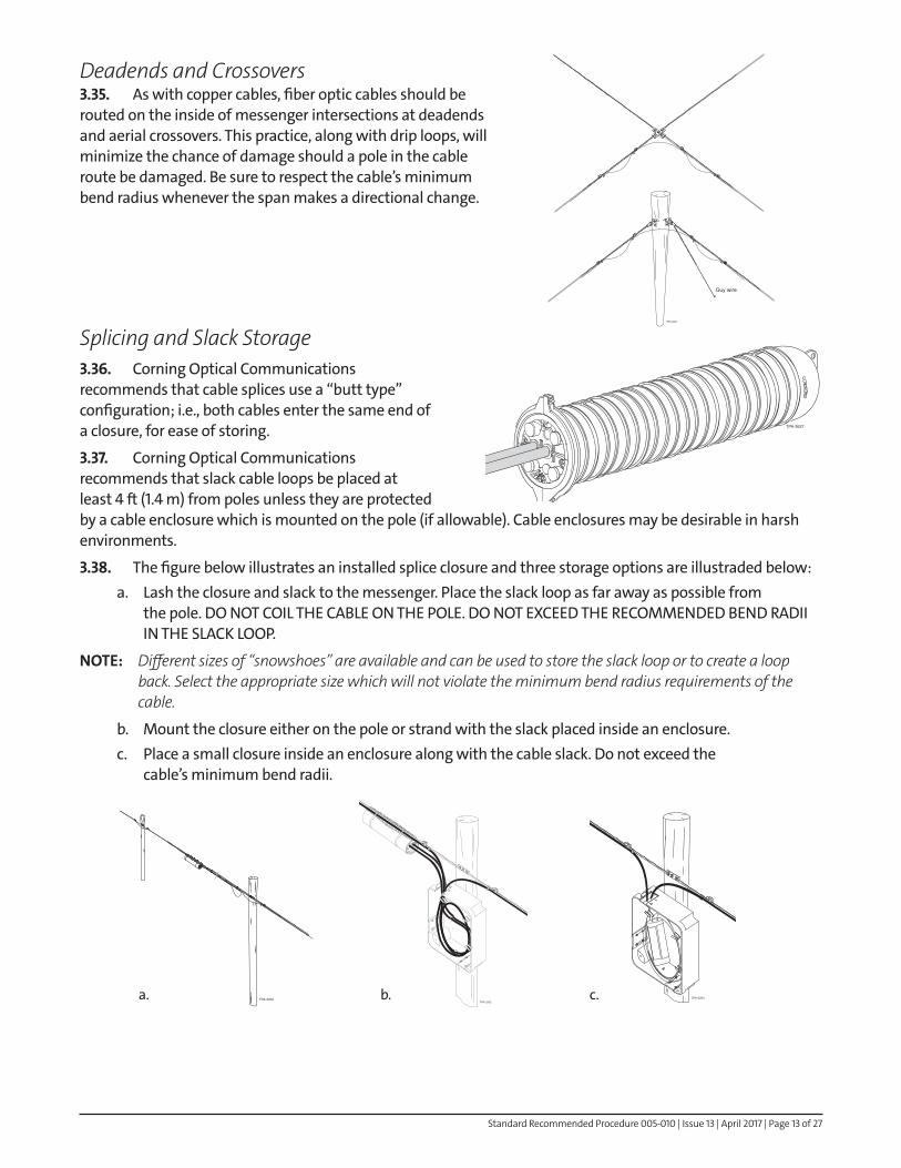
Splicing and Slack Storage3 .36 . Corning Optical Communications recommends that cable splices use a “butt type” configuration; i.e., both cables enter the same end of a closure, for ease of storing.
3 .37 . Corning Optical Communications recommends that slack cable loops be placed at least 4 ft (1.4 m) from poles unless they are protected by a cable enclosure which is mounted on the pole (if allowable). Cable enclosures may be desirable in harsh environments.
3 .38 . The figure below illustrates an installed splice closure and three storage options are illustraded below:a. Lash the closure and slack to the messenger. Place the slack loop as far away as possible from
the pole. DO NOT COIL THE CABLE ON THE POLE. DO NOT EXCEED THE RECOMMENDED BEND RADII IN THE SLACK LOOP.
NOTE: Different sizes of “snowshoes” are available and can be used to store the slack loop or to create a loop back. Select the appropriate size which will not violate the minimum bend radius requirements of the cable.
b. Mount the closure either on the pole or strand with the slack placed inside an enclosure.c. Place a small closure inside an enclosure along with the cable slack. Do not exceed the
cable’s minimum bend radii.
Guy wire
TPA-3200
TPA-3627
TPA-3202TPA-3203
TPA-3204a. b. c.

Standard Recommended Procedure 005-010 | Issue 13 | April 2017 | Page 14 of 27
3 .39 . Corning Optical Communications recommends that splicing be done on the ground, not in an aerial bucket. Consequently, it is necessary to allow enough slack at each splice point to bring both cables to the ground and into a convenient work area, plus 16 ft (5 m).
Packaging Removal3 .40 . Upon arrival at the job site, remove the packaging from each cable reel and remove the cable data sheet, if present, which documents individual fiber specifications for that particular reel.
Save the cable data sheets for maintenance and troubleshooting. Record the actual reel location in the aerial plant on the as-built drawing further document the system.
Storing Partial Cable Reels3 .41 . Excess cable remaining from an aerial installation is of value for future installations or emergency restorations. Store partial reels of cable as follows:
a. Pull all loose cable off the reel and re-reel the slack. Make sure that the wraps do not cross each other. Cap and seal all cable ends.
b. Securely fasten the cable end to the inside flange of the reel with a staple. This will prevent cable movement during transport.
c. Reels should be stored on edge and end-to-end in rows. Make sure that reels rest edge-to-edge with reels in adjacent rows to prevent damage to cables.
d. If the cable is stored outdoors, cover the reels for weather protection and make sure the storage area is free from rocks and debris which could cause damage during later moves.
4. Installation Methods — Equipment RequirementsNOTE: These procedures assume that the strand has already been installed and properly tensioned according to
your company’s practices.
4 .1 . The method chosen for placing lashed aerial fiber optic cable will depend on several variables:a. Pole line accessibilityb. Equipment and manpower resourcesc. Length of cable run
4 .2 . The Aerial Installation Equipment Requirements table, provides a comparison of the tools and equipment required for the moving reel method and two types of stationary reel cable installation. Additional equipment requirements are referenced under the respective instructions.
4 .3 . The installation technique and/or equipment used will determine the manner in which cable reels will be mounted on cable reel trailers or vehicles. Generally:
a. For drive-off (moving reel) installations: place reels so that the cable end can be pulled from the top of the reel towards the rear of the trailer or vehicle.
b. For back-pull (stationary reel) installations: place reels so that the cable end can be pulled from the top of the reel toward the front (tongue) of the trailer.
TPA-3205
TPA-3206

Standard Recommended Procedure 005-010 | Issue 13 | April 2017 | Page 15 of 27
4 .4 . Before beginning any installation, follow all of your company’s safety procedures to ensure that proper barricades, warning signs, etc., are in place.
5. Moving Reel (Drive-Off) Method5 .1 . In the moving reel or drive-off installation method, the cable is payed off its reel, raised to strand level, and lashed to the strand as the placement vehicle(s) move(s) along each span.This method requires vehicle access to the placement side of the pole line, and the cable route must be away from tree limbs, guy wires, and other obstructions. If the cable route has significant elevation changes, it is preferable to lash downhill.5 .2 . The moving reel method offers production and cost advantages over stationary reel methods as no cable blocks or other temporary support hardware are required. In addition, fewer crew members on the ground with two-way communications devices (e.g., radios) are required.
5 .3 . Begin the installation by unreeling an adequate, undamaged cable tail. This tail should be long enough to reach from strand level to a splicing vehicle on the ground, plus 16 ft (5 m) left at the pole. In addition, unreel enough slack to assure that the cable’s minimum bend radius is not exceeded when the cable is raised to strand level.
Generally, the reel-carrying vehicle should be 50 ft (15 m) ahead of the lasher to assure a proper cable minimum bend radius between the reel and strand level.
5 .4 . Position the aerial lift bucket so that the crew member riding in it has a 4 ft (1.2 m) working range on either side of the lasher.
X(1)X(2)X
XXXXX––––––X––––
Key: X = required– = not required M e t h o d
(Winch pulled)
Aerial lift (bucket truck) Reel trailerLaddersLasherLasher Pull Rope
“Shotgun” ArmLashing Wire ClampsCable Chute GuideCable BlocksCable Block LifterCable LifterPulling GripCorner Blocks and BracketsCable PullerHand-linePruning SticksWinch and LineWinch Line BlocksDynamometer
1 Not required if the aerial lift has adequate reel carrying capacity.2 Ladders not required if two lifts are available.3 50 ft (15 m) maximum spacing, additional blocks required when crossing streets, other utilities, etc.
–XXXXXXXX (3)
XXXXXXXXXX
–XXXXXXXX (3)
XXXXXXXXX
Optional
(hand pulled)Description Moving Reel
Table 6: Aerial Placement Equipment Requiirements
Stationary Reel Stationary Reel
TPA-3207

Standard Recommended Procedure 005-010 | Issue 13 | April 2017 | Page 16 of 27
NOTE: This procedure assumes that aerial lifts (bucket trucks) are available for the installation. If such vehicles are not available, the cable, lasher, and all required strand equipment must be raised to strand level with hand-lines by a craftsman on a ladder or on each pole.
5 .5 . Attach a lashing wire clamp to the strand 16 in (40 cm) from the centerline of the pole (or the distance necessary in order to maintain the desired bend radius of the cable in the slack-span or strand-to-pole transition).
5 .6 . Place the lasher, a 4-foot long “shotgun” arm, and a cable guide on the strand as described in Step 3.27. Ready the lasher by pulling enough lash wire out of the lasher to terminate in the lashing wire clamp as described in Step 3.29.5 .7 . Using an aerial lift, raise the cable to strand level and place it in the cable guide. Make sure that the cable moves freely and without stress as it leaves the ground. Do not allow the cable to exceed its minimum bend radius during this step (a).
NOTE: If you are not using a lift, pass a line through the cable chute guide and pull the cable up to the guide (b). Do not place stress on the cable and make sure that the cable’s minimum bend radius is not exceeded.
5 .8 . Verify that sufficient slack for splicing is available before securing the cable to the strand. Position the cable under the strand with a strap and spacer mounted 14 in (35 cm) from the pole center line [or 2 in (5 cm)] inboard of the lashing wire clamp location. As a temporary measure, the cable may be further secured to the strand with several wraps of friction tape.
16 ft (5 m)
50 ft (15 m)
S l
a c
k
R e q u i r e m e n t s
TPA-3208
TPA-3209
Cable
Pull lines
Cable guide
Lasher "Shotgun" arm
TPA-3210
(a)
(b)

Standard Recommended Procedure 005-010 | Issue 13 | April 2017 | Page 17 of 27
5 .9 . Position the cable in the guide, positioners (if present), and lasher. Adjust the lasher as described in Steps 3.27 a - c and the instruction manual provided with the lasher. The lashing wire should be placed around the lasher’s tension rollers and terminated in the lashing wire clamp.
5 .10 . Attach separate pull-lines to the lasher and the cable guide (and any accessories such as positioners).
NOTE: Corning Optical Communications recommends that the lasher be constantly observed so that the lasher can be stopped if the cable binds in the lasher. Depending upon the equipment available, such control may be assured by:
a. Pulling the lasher and its accessories by hand behind the reel-carrying vehicle with good communications between the crewman and the vehicle driver or,
b. Tying the pull-lines directly to the vehicle (do NOT attach any lines to the lift’s bucket or boom) with the observer stationed on the rear of the vehicle.
5 .11 . As the installation begins:a. Hold the cable end in place at the pole to prevent any movement along the strand until the lasher
operation has progressed 50 ft (15 m) down the strand.b. Pull the lasher and its accessories with a constant tension to prevent the lashing wire from wrapping
the fiber optic cable around the strand.c. Cable payoff must be surge-free and allow the cable to smoothly enter the cable guide at strand level.
Control reel rotation to prevent:• Free running, which could result in cable coming in contact with the ground.• Too-slow a payoff, which might subject the cable to excessive tension.
5 .12 . The reel-carrying vehicle must maintain its 50 foot distance ahead of the lasher, and drive as close to the pole line as conditions permit during the placement. Vehicle speed must assure complete control of the lashing operation.
The speed used in the moving reel method of fiber optic placement can average up to 150 ft (45 m) per minute, which is equivalent to a vehicle speed of 1.7 miles per hour.
5 .13 . Should it be necessary to stop the lashing operation mid-span, the crew member controlling the lasher must make sure that proper tension and bend radius are maintained on the cable.
5 .14 . Upon reaching each pole along the route, stop the vehicle to transfer the lasher and its accessories around the pole. If a crew member has been stationed on the pole to perform this task, he or she should remain on the side of the pole away from the strand until the lashing operation has stopped.
5 .15 . At the pole:a. Temporarily clamp the lashing wire to the strand.b. Transfer the guide, shotgun, and lasher to the other side of the pole as described in Section 3.c. If required, form a drip loop on the cable, as described in Section 3. Manually hold the drip loop in
place until the lasher has moved 50 ft (15 m) down the span.d. Make permanent lashing wire terminations on the strand before moving to the next pole.
TPA-3211

Standard Recommended Procedure 005-010 | Issue 13 | April 2017 | Page 18 of 27
5 .16 . Continue the drive-off installation, span-by-span, from the start-up point towards the end of the cable until the entire run is completely lashed.
5 .17 . At the end of the run, verify the slack-span and splicing requirements with the installation supervisor. Depending on the system plan, either leave the reel at this site or unreel adequate cable slack before cutting and capping the cable.
6. Stationary Reel (Back-Pull) Method6 .1 . In a stationary reel or back-pull installation, the cable is placed in at least two distinct operations:
• First the cable is pulled into place beneath the strand, suspended there by cable blocks.
• Lashing then begins at the far-end of the cable run, the lasher pulled back down the cable route towards the stationary reel.
6 .2 . There are a number of variations possible in the stationary reel installation method. Factors which affect the installation procedure include:
a. Length of the cable runb. The number of cables being placedc. Use of an unoccupied strand or overlashingd. The difficulty of the run (number of heavy corners, elevation changes, etc.)e. Manpower and equipment resources available.
6 .3 . This procedure outlines the steps common to all stationary reel installations, as well as variations of hand pulled and winch pulled stationary reel cable installation.
Cable Reel Placement6 .4 . Cable reel location can affect both the safety and efficiency of cable installation. Consider the following factors when determining cable reel locations.
a. System Design: Set up cable reels at end or splice points so that complete runs can be pulled into place without splicing. Set-up time is reduced if you can run cable in both directions from a splice point.
b. Traffic Impact: Select sites which have the least possible impact on vehicle and pedestrian traffic. Plan on adequate barricades, signs, and safety equipment to protect the work area.
c. Work Area Requirements: Cable reel sites require more than 50 ft (15 m) of working area between the cable reel and first pole in the run. In addition, the cable reel support bar of the trailer or reel-carrying vehicle must be level to minimize contact between the cable and reel flanges and ensure smooth cable payoff. Be prepared to level the reel by means of planks or other supports under the vehicle or leveling the ground in unpaved areas. Line up the center of the cable reel with the strand as closely as possible.
Fiber optic cable
b)
D I R E C T I O N O F L A S H I N G
D I R E C T I O N O F
C A B L E P U L L
TPA-3212
50 ft (15 m)
Reel should be in line with strand and level
TPA-3213

Standard Recommended Procedure 005-010 | Issue 13 | April 2017 | Page 19 of 27
6 .5 . Cable reel trailers should be disconnected from their tow vehicles before beginning an installation. Level the reel, and make sure that the wheels of the reel-carrying vehicle (trailer or truck) are securely chocked.
6 .6 . To guide the cable from its reel to its proper place under the strand, install a set-up bracket on the strand on the pole side opposite the cable reel.
For single cables, a cable guide chute can be attached to the bracket; for multiple cables, horizontally attach a 45-degree corner block to serve as a guide block. The set-up bracket’s swiveling features will accommodate cable de-reeled from off center-line of the strand.
6 .7 . If not factory-installed, attach a pulling grip and breakaway swivel to the end of each cable to be installed.
Cable Pullers6 .8 . Cable pullers are devices which ride either directly on a bare strand or over existing lashed cables. Available in single and multiple cable configurations, cable pullers link the pull-line to the pulling grip eye of a cable.
Brake-equipped cable pullers, which are used on unoccupied strands, lock onto the strand when the pull is stopped as cable tension exceeds pull tension.
Cable pullers suitable for overlashing rely on large rollers and are not brake-equipped. Either kind of puller should be used with a transfer harness to maintain cable tension while the puller is transferred around a pole.
7. Strand PreparationCable Blocks7 .1 . Cable blocks secured to the strand serve as temporary suspension supports for cable and winch-lines during stationary reel installations. Cable blocks range from 1 to 4 pounds (0.45 to 1.8 kg) in weight, accommodate single or multiple cables, and vary in operating features. Familiarize yourself with the type and operation of the cable blocks to be used in your installation before going to the job site.
7 .2 . Designed for general strand use, the cable blocks illustrated in this procedure are equipped with a cam-actuated, reversible locking mechanism.
Fixed in place while cable and/or pull-lines pass over their rollers, each lock is released when the back-pulled cable block pusher or the shotgun mounted in front of the lasher makes contact with the cable block. The cable block is then free to be pushed along the strand to the next pole or lifted from the strand if necessary.
a) b)TPA-3214
Direction of pullTPA-3215
TPA-3216
TPA-3217

Standard Recommended Procedure 005-010 | Issue 13 | April 2017 | Page 20 of 27
7 .3 . Cable blocks are secured in place on the strand with a cable block lifter mounted on a pruning (lift-up) stick.
7 .4 . All cable blocks must have the same orientation on the strand and have their locking levers (if present) set to release upon contact with the lashing equipment. Failure to do so will cause time-consuming delays as the locks will have to be manually released.
CAUTION: To reduce the chance of personal injury and/or damage to equipment, never stand directly beneath the strand when placing cable blocks. Stand several feet to the side of the strand to provide both better visibility of the block and increased safety should a block fall from strand level.
7 .5 . Cable blocks should be spaced at a maximum of 50 ft (15 m) intervals on the strand for fiber optic cable. If your company practice calls for smaller intervals, follow that practice. In the following special conditions, use the interval spacing indicated:
a. Over all roadways, use a maximum interval of 25 ft (7.5 m).b. Place an additional block(s)...
• over telephone drops.• over all locations where a need is indicated or perceived by federal, state, local, or company
regulations.• if the minimum bend radius of the cable is exceeded by any block.
7 .6 . Insufficient cable blocks can result in excess sagging of the fiber optic cable, more difficult pulls, and greatly increased chances of damage to the cable. Make sure that you have an adequate number of cable blocks before beginning the installation.
7 .7 . Heavy corners can cause the cable to jump out of a normal cable block, as well as place loads which exceed the block’s plastic or rubber roller specifications. At such locations, use a one-sheave pulling block to prevent the cable from riding out of the block.
7 .8 . The timing of cable block placement depends on the equipment used in the installation:
a. If a cable puller is used to 1) hand-pull the cable or 2) pull the pull/winch-line into position for a winch-assisted installation, place the blocks individually on the strand as the puller passes.
b. If a winch-line or pulling rope / tape is going to be pulled the length of the run and then lifted to strand level, place all the blocks in advance.
TPA-3218
TPA-3219

Standard Recommended Procedure 005-010 | Issue 13 | April 2017 | Page 21 of 27
Corner Equipment7 .9 . Use an 18-inch block for any pole offsets greater than 10 degrees (use degree symbol here if possible). Elevate the block by securing a rope to the shackle to ensure proper retention of the cable in the block. Attach the rope to one bottom pin of the shackle, bring the rope above the attachment point and back down to the opposite shackle pin.
Back-Pulling by Hand7 .10 . If installing the initial cable(s) on a strand:
a. Place a cable puller with pulling line on the strand.b. Feed a handline through the cable chute down to the pulling eye
attached to the cable.c. Begin unreeling the cable as you lift it up to strand level and through the
chute. Control the rotation of the cable reel to prevent free running of the cable.
d. Remove the handline and attach the pulling grip(s) to the cable puller.
7 .11 . Pull the cable puller along the strand, applying enough braking action on the puller to prevent the cable from winding around the strand. If the cable reel brake is set properly, the cable should move smoothly without excessive pulling force.
7 .12 . Continue pulling the cable until the cable end has gone approximately 25 to 30 feet (7.6 to 9 m) past the first cable block location. When you relax the pulling force, the cable puller’s brake should lock onto the strand. Lift and secure a block onto the strand, and then use a cable lifter to place the cable onto the cable block’s roller.
NOTE: If the cable appears to oscillate excessively in the first span of the cable run, additional blocks secured at 20 ft (6 m) intervals can minimize oscillation during the pull.
7 .13 . Continue the hand-pull, span-by-span pulling the cable along the strand and adding cable blocks for support.
Pause 30 ft (9 m) past each block location so that a crew member can place the next cable block on the strand. Make sure that the puller’s brake maintains tension on the cable to prevent excessive sag in the fiber optic cable.
TPA-3262
Pulling grip
b)
Cable pullerCable
lifter
TPA-3221

Standard Recommended Procedure 005-010 | Issue 13 | April 2017 | Page 22 of 27
7 .14 . At each pole, a crew member must transfer the cable puller from one side of the pole to the other. As noted in step 6.8, the puller ideally should be equipped with a transfer harness which can maintain tension on the cable(s) while the puller is moved around the three-bolt clamp on the pole.
7 .15 . As the cable nears the end of the run, slow the pull. At the end of the cable run:a. Install another cable chute to guide the cable down from the strand.b. Route a handline through the chute to the pulling grip(s) to maintain cable tension.c. Remove the cable puller from the strand.d. Pull enough slack to take care of the slack-span and splicing needs. Temporarily secure the cable on
the final pole and firmly brake the cable reel to maintain sufficient tension to prevent excessive sag along the run.
7 .16 . If pulling cable, the run should now be ready for lashing. Proceed to step 7.32. If the hand-pulling operation involved only pull-line placement, proceed to step 7.24.
Winch-Assisted Pulls7 .17 . Winches can be particularly useful in pulling long runs of fiber optic cable into place. A winch-assisted pull involves at least four steps:
a. Position the winch or power reel at the far end of the run.b. Place a pull-line or winch-line in cable blocks the length of the run and attach the line to the reeled
cable.c. Pull the cable into place beneath the strand by retrieving the pull-line with the winch.d. Pull the lasher back towards the cable reel.
NOTE: Cable pullers may be used when using a winch to make single or multiple cable pulls. Cable puller use, however, requires an adequate number of crew members to remove and replace each cable block as the puller passes by on the strand. Further, the crew must stop the pull at each pole for cable puller transfer around the pole.
7 .18 . If two or more fiber optic cables must be placed and lashed, it will be necessary to individually pull each cable into place using multiple blocks.
7 .19 . Generally, greatest production in single-cable, winch-assisted pulls is possible from carefully controlled pulls which do not use cable pullers. If blocks are properly placed and pulling tensions monitored, winch-assisted pull speeds may approach 150 ft (45 m) per minute.
Tension-limiting winch
D I R E C T I O N O F P U L L
Pull line
b)
TPA-3222

Standard Recommended Procedure 005-010 | Issue 13 | April 2017 | Page 23 of 27
7 .20 . As with hand-pulled stationary reel installations, monitor the entire cable route during the cable pull. Station crew members equipped with two-way communications so that the entire run is under observation, making it possible to instantly stop the pull, if necessary. In addition, use a dynamometer to measure tension on all long cable pulls and short, difficult sections where pulling force might approach or violate the cable’s specifications.7 .21 . Begin the installation by placing the winch in line with the far end of the strand. Position the winch 50 ft (15 m) from the final pole in the run to assure that the fiber optic cable’s minimum bend radius is not exceeded when the cable end reaches the end of the cable run.7 .22 . Prepare the cable route by placing cable blocks at all required points. Install steel winch-line blocks at all heavy corners and stress points (e.g., the top or bottom pole in a section with severe elevation changes).
7 .23 . Unreel and pull the winch or pull-line the length of the cable run to the cable reel. The pull-line may be: a. Pulled the length of the run on ground level and then lifted up to the cable blocks with a cable
block lifter or wire raising tool.b. Hand-pulled into place with a cable puller on a bare strand. The latter method is useful if the
terrain or ground cover would make ground-level pulling difficult.
NOTE: Various types of pull-lines have been successfully used with fiber optic cable. Selection of a pull-line will depend on the length and condition of pull. Available pull-line materials include aramid yarn, wire rope, and polypropylene. For pulls using winches, materials with low stretch such as aramid yarn and wire rope can prevent cable surging. Pull-lines can have a round cross-section or be in a tape configuration. Consult your company’s standard practices with regards to pull-line material.
7 .24 . After the pull-line has been placed in all of the blocks, securely attach its free end to the eye of the cable’s pulling grip. Use knots or other means appropriate to the pull-line being used.This attachment point should not bind in the rollers, corner blocks, or cable blocks during the pull. Vinyl tape-wraps around the attachment point can help eliminate potential binding points.7 .25 . Station personnel along the entire route and verify two-way communications between these observers and those manning the cable reel and winch.
7 .26 . Perform a final careful check of the cable reel. The inside flanges of the cable reel should be free from rough edges which might damage the cable.
7 .27 . Apply tension on the pull-line with the winch. The dynamometer should be in clear view of the winch operator. At the other end of the run, adjust the cable reel brake so that the pulling tension on the cable does not exceed the cables’ maximum recommended limit.7 .28 . Begin the pull slowly and gently. If no problems are observed along the route or indicated by the dynamometer, smoothly increase the pull speed to its maximum desired rate. The cable should flow smoothly and be free from oscillation. Maintain full control of the cable during the pull.
NOTE: If the pull must be stopped suddenly, cable may “run out” of some of the cable blocks due to cable fed to the strand by the inertial rotation of the reel. Before resuming the pull, make sure that the cable is properly placed in all the blocks and that any excess slack in the run has been carefully taken up without kinking or twisting.
Winch-line blocks
TPA-3223
TPA-3224

Standard Recommended Procedure 005-010 | Issue 13 | April 2017 | Page 24 of 27
7 .29 . As the cable approaches the end of the pull, slow down the winch. Continue the pull until sufficient cable for the slack-span and splicing has been pulled down from strand level.
CAUTION: DO NOT feed fiber optic cable onto the winch or power reel at the end of the pull. Failure to observe the cable’s minimum bend radius can cause damage to the cable. Detach the pulling grip and the pull-line before the grip makes contact with the winch reel. If necessary, pull the required slack by hand.
7 .30 . Stop the winch. Secure the cable at the last pole with a grip or several hitches in the pull rope until lashing begins. Lock the cable reel at the other end of the run to maintain tension on the cable.
7 .31 . Apply a protective cap to the cable end after removing the pulling grip. Make sure that all cable slack is properly coiled and protected from vandalism if it will be left unattended during the lashing procedure.
Back-pull Lashing7 .32 . During lashing, excess cable slack on the run is fed back towards the reel. Man the reel during lashing so that this slack can be taken up by the reel.
7 .33 . Prepare the run for lashing as follows:a. Remove the cable chute from the strand.b. Install the necessary straps and spacers at the pole.c. Hold the cable in place during the first 50 ft (15 m) of lashing.d. Mount the lasher, positioner (if lashing multiple cables), and cable block pushers on the strand
as described in Section 3.
7 .34 . Begin the lashing process by having a crew member pull the lasher/pusher tow ropes along the path of the strand. Pull the lasher with a down-ward pressure to keep the lasher mechanism spinning. Maintain tension on the lasher to prevent the lashing wire from wrapping the fiber optic cable around the messenger.
7 .35 . Pull the lasher the length of the span to the next pole, pushing the cable blocks before the lasher as it progresses down the span. At the next pole, remove the cable blocks which have accumulated and lower them to the ground with a line.
7 .36 . Before releasing the lasher brake, temporarily clamp the lashing wire to the strand with a catch-off clamp. After the lashing wire is secured, pull enough lashing wire out of the lasher for termination and make the appropriate cut. Transfer the lashing equipment to the other side of the pole.
7 .37 . If the system design calls for splices on a particular pole, leave the appropriate amount of slack. If no splices are required, straps, spacers, and a drip loop can be installed on the pole before the lashing process continues. Check all work at the pole before moving down the run.
7 .38 . Continue the lashing process, span-by-span, from the winch-end of the run back toward the cable reel until the entire run is lashed. The run should be completely lashed, properly sagged, and excess cable slack re-reeled at this time.
7 .39 . Consult the outside plant engineer or the system design plan before cutting the cable at the cable reel end. Make sure that adequate slack is provided for splicing, routing, or other needs. Cap the cable end after cutting it as described in Step 1.19.
b)
D I R E C T I O N O F L A S H I N G
TPA-3225

Standard Recommended Procedure 005-010 | Issue 13 | April 2017 | Page 25 of 27
8. Combination Methods8 .1 . If the cable route has terrain, trees, or other obstructions which prohibit the complete use of a moving reel installation, stationary reel methods can be used to pull in the cable in the vehicle-inaccessible sections.
8 .2 . Set up cable reel at an end point of the route in which the moving reel method is practical. Install the vehicle-inaccessible spans using a stationary reel method.
8 .3 . Following placement and lashing of this section, install the vehicle-accessible remainder of the cable route with the moving reel method.
South
Campus
North
Campus
RIGHT
LANE
CLOSED
STOP
UTILITY
WORK
AHEAD
D I R E C T I O
N
O F P
U L L
D I R
E C T I O N
O F L
A S H I N G
TPA-3226
South
Campus
North
Campus
UTILITY
WORK
AHEAD
RIGHT
LANE
CLOSED
STOP
M O V I N G R E E L S E C T I O N
TPA-3227

Standard Recommended Procedure 005-010 | Issue 13 | April 2017 | Page 26 of 27
8 .4 . If the destination of the route is also inaccessible to vehicles, unreel and figure-eight the cable to gain access to the other end of the cable. Pull the cable into place beneath the strand with a stationary reel method.
8 .5 . This last section must be lashed from the moving reel / stationary reel transition point towards the free end of the cable.
South
Campus
North
Campus
UTILITY
WORK
AHEAD
RIGHT
LANE
CLOSED STOP
D I R E C T I O N O F P U L L
TPA-3228
South
Campus
North
Campus
UTILITY
WORK
AHEAD
RIGHT
LANE
CLOSED
D I R E C T I O N O F L A S H I N G
TPA-3229

Standard Recommended Procedure 005-010 | Issue 13 | April 2017 | Page 27 of 27
Corning Optical Communications LLC • PO Box 489 • Hickory, NC 28603-0489 USA 800-743-2675 • FAX: 828-325-5060 • International: +1-828-901-5000 • www.corning.com/opcomm
Corning Optical Communications reserves the right to improve, enhance, and modify the features and specifications of Corning Optical Communications products without prior notification. A complete listing of the trademarks of Corning Optical Communications is available at www.corning.com/opcomm/trademarks. All other trademarks are the properties of their respective owners. Corning Optical Communications is ISO 9001 certified. © 1985, 2017 Corning Optical Communications. All rights reserved.
9. Post-Construction Inspection9 .1 . Prior to splicing, a thorough inspection of the aerial plant must be made. Make this inspection on a span-by-span, foot-by-foot basis. The inspector should make notes regarding clean-up work on a copy of the system plans.
9 .2 . Check for following items during the postconstruction inspection:a. Conformance of the as-built aerial plant to the engineering plans. The exact location of all splice
points should be noted so that they can be incorporated into the final design plans.b. Presence of kinked or damaged cable.c. Improperly installed or missing drip loops.d. Improperly installed or missing grounds.
9 .3 . Upon completion of this inspection, the appropriate party (contractor, in-house construction crew, etc.) must correct all deficiencies.
Reinspect the corrections. When the aerial plant passes this final construction inspection, the splicing, activation, and final alignment of the plant may proceed according to your company’s normal operating procedures.