LaserStacker: Fabricating 3D Objects by Laser Cutting and...
8
LaserStacker: Fabricating 3D Objects by Laser Cutting and Welding Udayan Umapathi, Hsiang-Ting Chen, Stefanie Mueller, Ludwig Wall, Anna Seufert, Patrick Baudisch Hasso Plattner Institute, Potsdam, Germany {firstname.lastname}@hpi.de ABSTRACT Laser cutters are useful for rapid prototyping because they are fast. However, they only produce planar 2D geometry. One approach to creating non-planar objects is to cut the object in horizontal slices and to stack and glue them. This approach, however, requires manual effort for the assembly and time for the glue to set, defeating the purpose of using a fast fabrication tool. We propose eliminating the assembly step with our system LaserStacker. The key idea is to use the laser cutter to not only cut but also to weld. Users place not one acrylic sheet, but a stack of acrylic sheets into their cutter. In a single process, LaserStacker cuts each individual layer to shape (through all layers above it), welds layers by melting material at their interface, and heals undesired cuts in higher layers. When users take out the object from the laser cutter, it is already assembled. To allow users to model stacked objects efficiently, we built an extension to a commercial 3D editor (SketchUp) that provides tools for defining which parts should be connected and which remain loose. When users hit the export button, LaserStacker converts the 3D model into cutting, welding, and healing instructions for the laser cutter. We show how LaserStacker not only allow making static objects, such as architectural models, but also objects with moving parts and simple mechanisms, such as scissors, a simple pinball machine, and a mechanical toy with gears. Author Keywords: rapid prototyping; laser cutting. ACM Classification Keywords: H5.2 [Information Figure 1: LaserStacker produces laser cut objects consisting of multiple layers of acrylic without requiring manual assembly: interfaces and presentation]: User Interfaces. It assembles the object by not only cutting with the laser, but INTRODUCTION also welding, and healing the cut. Three example objects: (a) a While 3D printers allow fabricating complex 3D geometry, pinball table with spring (10 min), (b) an architectural model they are inherently slow. Laser cutters, in contrast, allow for of our university campus (7 min), and (c) a simple but much faster fabrication, making them a popular tool for functional pair of scissors (3 min). rapid prototyping. However, they can produce only 2D One standard approach to creating non-flat objects is to cut geometry, so the results are inherently flat. horizontal slices of the object (e.g. using a feature from Permission to make digital or hard copies of all or part of this work for Autodesk 123D [1]). This requires manual assembly with personal or classroom use is granted without fee provided that copies are alignment sticks and glue, and additional time waiting for not made or distributed for profit or commercial advantage and that copies the glue to set. This limits the speed of the prototyping bear this notice and the full citation on the first page. Copyrights for process. components of this work owned by others than ACM must be honored. Abstracting with credit is permitted. To copy otherwise, or republish, to One way to overcome this limitation is to use a moving post on servers or to redistribute to lists, requires prior specific permission platform to automatically add and glue fabricated layers on and/or a fee. Request permissions from [email protected]. UIST '15, November 08-11, 2015, Charlotte, NC, USA top of each other, a process called Laminated Object © 2015 ACM. ISBN 978-1-4503-3779-3/15/11…$15.00 DOI: http://dx.doi.org/10.1145/2807442.2807512 575
Transcript of LaserStacker: Fabricating 3D Objects by Laser Cutting and...

++++++LaserStacker+Fabricating+3D+Objects+++++++++++++++++++++++++++by+Laser+Cutting+and+Welding+
Udayan Umapathi Hsiang-Ting Chen Stefanie Mueller Ludwig Wall Anna Seufert Patrick Baudisch
Hasso Plattner Institute Potsdam Germany firstnamelastnamehpide
ABSTRACT+ Laser cutters are useful for rapid prototyping because they are fast However they only produce planar 2D geometry One approach to creating non-planar objects is to cut the object in horizontal slices and to stack and glue them This approach however requires manual effort for the assembly and time for the glue to set defeating the purpose of using a fast fabrication tool
We propose eliminating the assembly step with our system LaserStacker The key idea is to use the laser cutter to not only cut but also to weld Users place not one acrylic sheet but a stack of acrylic sheets into their cutter In a single process LaserStacker cuts each individual layer to shape (through all layers above it) welds layers by melting material at their interface and heals undesired cuts in higher layers When users take out the object from the laser cutter it is already assembled
To allow users to model stacked objects efficiently we built an extension to a commercial 3D editor (SketchUp) that provides tools for defining which parts should be connected and which remain loose When users hit the export button LaserStacker converts the 3D model into cutting welding and healing instructions for the laser cutter
We show how LaserStacker not only allow making static objects such as architectural models but also objects with moving parts and simple mechanisms such as scissors a simple pinball machine and a mechanical toy with gears
Author Keywords rapid prototyping laser cutting
ACM+ Classification+ Keywords H52 [Information Figure 1 LaserStacker produces laser cut objects consisting of multiple layers of acrylic without requiring manual assemblyinterfaces and presentation] User Interfaces It assembles the object by not only cutting with the laser but
INTRODUCTION+ also welding and healing the cut Three example objects (a) a While 3D printers allow fabricating complex 3D geometry pinball table with spring (10 min) (b) an architectural model they are inherently slow Laser cutters in contrast allow for of our university campus (7 min) and (c) a simple but much faster fabrication making them a popular tool for functional pair of scissors (3 min) rapid prototyping However they can produce only 2D One standard approach to creating non-flat objects is to cut geometry so the results are inherently flat horizontal slices of the object (eg using a feature from Permission to make digital or hard copies of all or part of this work for Autodesk 123D [1]) This requires manual assembly with personal or classroom use is granted without fee provided that copies are alignment sticks and glue and additional time waiting for not made or distributed for profit or commercial advantage and that copies the glue to set This limits the speed of the prototyping bear this notice and the full citation on the first page Copyrights for processcomponents of this work owned by others than ACM must be honored Abstracting with credit is permitted To copy otherwise or republish to One way to overcome this limitation is to use a moving post on servers or to redistribute to lists requires prior specific permission platform to automatically add and glue fabricated layers on andor a fee Request permissions from Permissionsacmorg UIST 15 November 08-11 2015 Charlotte NC USA top of each other a process called Laminated Object copy 2015 ACM ISBN 978-1-4503-3779-31511hellip$1500 DOI httpdxdoiorg10114528074422807512
575
Figure 2 Creating the s cissors w ith LaserStacker
To illustrate LaserStackerrsquos workflow Figure 2 illustrates how to make the pair of scissors (a) The user starts by modeling the scissors in our LaserStacker editor which we implemented as an extension to the popular 3D editor SketchUp [21] (see section ldquoLaserStacker editorrdquo) (b) After the user finished modeling the user hits the export button which causes LaserStacker to slice the 3D model into layers and to encode the information for each layer into a 2D vector format (svg) In addition LaserStacker exports a file with corresponding power settings for the laser (las) (c) To fabricate the scissors the user places a stack with the appropriate number of acrylic sheets (here three) into the laser cutter loads both files into the laser cutter control panel and executes the job (d) The laser cutter produces the scissors in a single integrated process consisting of cutting all layers welding the layers that should be connected and healing the undesired cuts When the user opens the case of the laser cutter the pair of scissors is
Manufacturing [5] However this requires specialized hardware In industry another approach is to use high-frequency lasers to weld material sheets together [2] However this process not only require a special type of laser but also special material in the form of transmissive and absorbent material sheets
In this paper we propose a different approach to overcome the need for manual assembly Instead of adding layers one by one we suggest putting an entire stack of acrylic sheets at once into the laser cutter then to use our cutting welding and healing technique to fabricate non-planar objects
LASER+STACKER++ Figure 1 shows three example objects created using LaserStackermdashan architectural model of our university campus a simple but functional pinball table and scissors
already assembled After removing the surplus material the scissors are ready to be used to actually cut paper (Figure 1c)
We now look at step (d) the cutting-welding-healing-releasing process and step (a) the 3D editor in additional detail
The+CuttingIWeldingIHealingIReleasing+process+ LaserStacker produces the scissors from three layers illustrated by Figure 3 The bottom layer contains the first scissor outline The middle layer contains the second scissor outline and an axle around which it rotates The top layer contains a rectangular cover connected to the axle that prevents the scissor blades from falling apart
Figure 3 The s cissors c onsist of three l ayers
Figure 4 illustrates the steps of the fabrication process
(a) To create the scissor outline in the bottom layer LaserStacker first cuts through the top layer then through the middle layer and finally through the bottom layer In this particular case of cutting the scissor outline this happens to be a desirable effect in that it already cuts the scissor outline in the middle layer We will remove the scissor outline in t he top l ayer (surplus m aterial) later
(b) LaserStacker now cuts the axle into the middle layer This requires LaserStacker to cut the top layer as well which in this case does not fit our intended design LaserStacker will thus heal this cut in a later step
Figure 4 The cutweld process illustrated at the example of the scissors
(c) LaserStacker welds the axle in the middle layer to the scissor outline in the bottom layer Like any welding in a lower layer this causes all layers above to be welded as well causing the axle to be connected all the way through
576
to the top layer In this particular case this is desired In other cases LaserStacker would release the weld later We now have two scissor blades combined by a rotary joint however the rotary joint still lacks a cover
(d) LaserStacker cuts the axle cover in the top layer This cut only touches the top layer thus has no side effects on any of the other layers
(e) LaserStacker now heals the cut between the axle and the axle cover in the top layer that was caused in step (b)
(f) We take the scissors out of the cutter After removing the surplus material the scissors are complete and we are ready to cut paper with them
TECHNICAL+DETAILS+LASER+STACKING+PROCESS+ We now provide additional technical explanations for the cutting welding healing and releasing techniques
Cutting+ Cutting is a standard function of laser cutters However when cutting through a stack of layers there are two things to note (1) Cutting the lower layer requires cutting through all layers above LaserStacker can heal the undesired cut on the top layer later (2) Cutting a lower layer also welds all layers above together For example in Figure 4 this happens in (a) when the scissor blade is cut in the bottom layer LaserStacker can later release the weld to break the undesired connection
Welding+ To weld two layers LaserStacker cuts through the top layer plus roughly into 30 of the bottom layer (Figure 5) which results in material being liquefied along the cut After a few seconds the liquefied acrylic solidifies again and welds these two layers together To weld multiple layers LaserStacker repeats the process for each pair As we show in the Technical Evaluation section a welding of 10cm length with a 1mm cut width can sustain about 15kg weight ie 1470 kPa
Figure 5 Welding two sheets of acrylic (a) the laser cuts through the top layer and into 30 of bottom layer (b) the
heat along the laser path welds both layers
Any weld tends to require two types of repair First welding cuts through one or more layers above LaserStacker resolves this by healing the cut Second as illustrated by Figure 5b welding always connects layers on both sides of the cut Since only one of the two sides is typically desired LaserStacker later releases the weld on the other sides
Healing+a+cut+ As illustrated by Figure 6 LaserStacker heals a cut in two steps (a) LaserStacker creates a new cut in close proximity to the gap (typically 04mm) (b) Due to thermal expansion the isolated material sliver bends sideways during the cutting thereby bridging the cut LaserStacker now welds this bridge to the two sides To do this LaserStacker first defocuses the laser by moving the cutting table away from the lens It then uses the defocused laser to heat up the region until the bridging sliver fuses with the material left and right When it cools down the piece forms a strong side-by-side weld with the remaining acrylic and thereby closes the gap While the cut is still visible to the human eye the weld is strong enough that it allows the part to perform a mechanical function Our technical evaluation shows that healing can sustain about 784 kPa (half the strength of welding)
Figure 6 Healing a cut (a) creating a new cut in close proximity (b) defocusing the laser and melting the piece to
(c) create a strong side-by-side weld
Releasing+a+weld+ To release the undesired side of a weld (eg the left side in Figure 7a) LaserStacker creates another cut into that side in very close proximity (typically 02mm) The cut is so close that the material evaporates completely thereby releasing the weld
Figure 7 Releasing a weld (a) creating a new cut in very close proximity (b) the material evaporates and releases the weld
LASERSTACKER+EDITOR+ To help users design stacked objects using LaserStacker we built a custom editing tool for it The tool is implemented as an extension to the standard 3D modeling software SketchUp [21]
Figure 8 illustrates how we modeled the scissors from our earlier example (a) We create a blank project by specifying the number of layers (here 3) and the size of the work plane (here 200mm x 50mm) (b) We then define the thickness
577
for each layer here 28mm each The LaserStacker editor responds by displaying a three-layer project in its 3D view The layers later on help users to align their design
Figure 8 Define (a) number of layers (b) layer thicknesses
As shown in Figure 9a we then draw the outline of our scissor onto the ground plane using SketchUprsquos 2D path tool We now extrude the path using SketchUprsquos pull tool The LaserStacker extension causes the pull tool to snap the extrusion to the individual layers making it easy to get the thickness right (b) We now create another identical outline on the middle layer by extruding the shape of the first outline further to the middle layer (c) By default the LaserStacker editor assumes that the user would like layers to be welded To allow the two blades to move independently we brush them using LaserStackerrsquos loosen tool LaserStacker responds by coloring the two blades differently indicating that they are now disconnected
Figure 9 (a) Sketch scissors outline use pull tool to extrude to first scissor outline then (b) second scissor outline (c) Use
loosen tool to disconnect both layers
Figure 10 shows how we add the scissorsrsquo axle We import an axle with cover master shape from the LaserStacker master shape library which contains simple mechanisms and other commonly used parts
Figure 10 (a) Loading an axle from the master shape library (b) The axle has an extra strong weld in the middle
The axle with cover contains a circular cut with a strong weld in the middle which is achieved by cutting the spiral in the center We scale the axle with cover to the right size and place it in the correct location on the scissors
We are done modeling now We click the export button which causes LaserStacker to convert the 3D model into an svg file containing 2D vector lines and a corresponding las file with the power settings for the laser (Figure 11) These two files together encode the cutweldhealrelease process described earlier We load the files into the standard control panel of our laser cutter and send the cut job to the laser
Figure 11 LaserStacker exports (a) an svg file with 2D paths and (b) a laser settings file with the powerspeed settings here
we already loaded it into the laser cutterrsquos control panel
CONTRIBUTION+BENEFITS+ The main contribution of this paper is a system called LaserStacker that allows users to fabricate stacked objects without manual assembly using a new cutweld fabrication process We provide a custom editor for this class of objects (as an extension to the SketchUp 3D editor) The key technical contribution is the export function that translates the 3D model into an instruction set for a standard laser cutter which produces that object
The cutweld process behind LaserStacker is a fast laser fabrication technique useful for making functional objects from stacked sheets of acrylic Its main advantage is that it eliminates the need for assembly Unlike LaserOrigami [17] which only produces origami-like geometry LaserStacker allows building objects with moving parts
The objects produced by our system can be grouped into three classes (1) pyramidtapered shape whose top layers are smaller than the bottom layers (eg the architectural model in Figure 1a the robot in Figure 12a and the air hockey table in Figure 12c) This works without healing (2) Objects which top layers are larger than the bottom layers require healing (eg the head and tail of the mechanical horse toy in Figure 12b are larger than the bottom layer) (3) In addition to the main class of objects that are produced in a fully automated fashion users can also feed additional material halfway into the process this
578
process allows creating also objects that have surplus material inside (eg in Figure 12b users have to remove the surplus between the pair of gears before they can add the top layer)
Figure 12 Different classes of objects (a c) pyramid shapes do not require healing (b) Other shapes require healing The
little robot and the mechanical horse toy take 25 min to fabricate while the pinball table takes 14 min due to its
thicker layers
RELATED+WORK+ LaserStacker builds upon the research fields of personal fabrication laser cutting and automated assembly techniques
Personal+Fabrication+ Personal fabrication machines such as laser cutters and 3D printers allow users to prototype one-off objects [7] Recently researchers started to develop tools that allow users to build increasingly complex objects such as free-form speakers [12] objects with integrated displays [23] interactive objects based on a single camera [19] kinematic objects [4 22] and physical visualizations of data [13]
Since a key element in prototyping is speed researchers looked at how to speed up fabrication by either massively parallelizing the printing process using multiple heads [8] by assembling objects layer-wise from prefabricated voxels of equal size [10] or by fabricating intermediate versions of a prototype as fast low-fidelity previews [16]
Creating+3D+Objects+with+Laser+Cutters+ As a fast alternative to 3D printers researchers proposed techniques to build 3D objects using laser cutters Multilayer-models [11] for instance are stacks of 2D
images that users glue onto acrylic sheetsmdashthe images give the appearance of a 3D object In wire mesh design [6] a 3D scaffold is created by laser cutting intersecting planar pieces which are then used to bend the wire mesh into shape Platener [3] is a research prototype that converts 3D model into laser-cuttable parts while preserving the functionality of the 3D object
The most common approach to represent a 3D model with 2D parts is to convert it to a stack of 2D plates This functionality is included in many commercial products such as the 3D editor Autodesk 123D [1] Hildebrand et al [9] take this approach further by slicing parts of the model in different orientations to better approximate the shape
Automating+Assembly+ Several researchers and industrial engineers have proposed ways to automate the assembly of 2D parts into 3D objects
Laminated-Object Manufacturing [5] is a rapid prototyping technique that cuts layers of adhesive-coated materials one-by-one to shape using a knife or a laser cutter The layers are stacked using a moving platform and automatically laminated The MCor 3D printer [15] for instance uses regular office paper to fabricate 3D objects Similarly the layered fabric 3D printer [18] uses 2D sheets of fabric to form soft 3D objects
Laser Welding [2] is an industrial technique used to fuse layers of material together Unlike the work presented in this paper it uses special wavelength lasers to weld top layers made from transmissive material to non-transmissive bottom layers that absorb the energy
LaserOrigami [17] automatically creates 3D objects by cutting and folding a single sheet of acrylic in an integrated process While LaserOrigami can only create origami-like geometry LaserStacker also allows building objects with moving parts
SOFTWARE+IMPLEMENTATION+ To allow readers to replicate our technique we now describe the internal working of our software and hardware
Converting+a+3D+model+into+a+set+of+2D+contours+ In order to convert a 3D model into 2D contours for laser cutting we first find all edges that are parallel to the x-y plane ie these are the edges that lay on one of the layers When the user extrudes the face upward each edge has a corresponding parallel edge on one of the top layers The distance between a pair of edges defines through how many layers the laser cutter has to cut We thus replicate the same edge onto all layers that also have to be cut
In addition our software tests if each cut on a bottom layer is reachable ie if all layers above were also cut If a cut is not reachable we replicate the cut on each top layer
Exporting+the+laser+cut+path+and+laser+settings+file++ To generate the laser path file we draw the extracted contours into an svg file We iterate over the layers
579
starting from the top Since each layer needs different laser speed settings we draw the contours of each layer in a separate color
The laser settings file (for our laser cutter model las) is a text file with a list of colors that maps onto different speed and power settings for the laser cutter To compensate for the limited number of power settings in some laser cutter software our extension is capable of generating multiple sets of svg + power setting files
Identifying+cut+and+weld+edges+ Since cutting and welding use different laser settings we differentiate between edges for welding and edges for cutting Since the LaserStacker color-codes which components are connected our software looks at the color of the faces around an edge to identify if it should be cut or welded (same color = weld different color = cut)
Computing+the+healing+path+ To identify which parts require healing our software takes all cut lines on lower layers and projects them onto the top layer If an edge lies inside some geometry on the top surface this part needs to be healed Otherwise the edge is part of the surplus material and does not require healing as it is not part of the final object On export our software automatically generates the additional offset edges that are required for healing
Not all compositions of cutting-welding-healing commands are possible In conditions where healing is not possible eg more than one healing operation at the same location in different layers or healing results in trapped material In these cases the LaserStacker Editor informs the user by color-coding the layer in the 3D model
Master+shapes+ For the master shape library we created 3D models of several mechanical elements with different pre-defined parameters LaserStacker loads them according to the scale of the current design
CALIBRATING+LASER+CUTTER+SETTINGS++ To allow readers to replicate our results we describe the calibration procedure that we used to determine the laser power setting for cutting and welding different layers in the stack The required settings (power speed cut depth) depend on the hardware setup and the acrylic in use The user only needs to perform the calibration procedure once before using LaserStacker for the first time Currently our procedure assumes that the stack consists of acrylic sheets with the same thickness
Focus+point+of+the+laser+ LaserStacker always keeps the laser beam focused on the top of the stack ie for welding layers that are further apart from the focal point we increase the power of the laser (see Figure 13)
We focus on top of the stack for two reasons (1) It allows for larger stacking heights since focusing on the top layer
keeps the stack at a constant distance to the lens (thus avoiding collisions) For instance our lens has a 20mm focal length which means that focusing on lower layers would limit the stack height to 20mm (2) Focusing the laser inside the stack caused burning We believe the burning happens because a deeper focus point results in a cone shaped laser beam that 1) generates diffusion and refraction when going through top layers and 2) creates a funnel that ignites the acrylic as the laser heats up the remaining edges of top layers
Figure 13 We increase the laser power as we move away from the focal point of the laser
Estimating+the+Laser+Power+Setting+ To minimize the fabrication time we always set power to 100 and only control the cutting speed The slower the laser moves the more heat is accumulated at a certain location
We formulate the curve for laser speed as
$ = amp(
The recursive formula takes as inputs the thickness of the acrylic t the cutting speed for a single layer of acrylic S and the cutting speed for the nth layer and outputs the cutting speed for the n+1th layer It implies that given the cutting speed of the first layer the formula can output the cutting speed for each layer in the stack
Both a and b are parameters that we estimate based on experimental data (see section Calibration Procedure)
The proposed recursive formula implies that we can estimate the cutting speed of the n+1th layer based on the speed of the nth layer This reflects our assumption that a specific portion of energy is lost in the area above the layer that is currently being cut due to (1) the reflection of the laser as it goes through layers (2) the defocus of the laser and (3) the remaining residues in top layers
Calibration+Procedure+ We obtain the parameters a and b by first collecting data points for stacks of different heights and then estimating the values of a and b using a standard curve fitting procedure
We collected data points using the calibration pattern shown in Figure 14 It consists of six squares with different stacking heights from one to six layers We iteratively tried different speed settings until we found the maximum speed setting for welding at a specific layer height
580
10
9
8
CuttingSpeed()
7
6
5
4
3
2
1
0 0 5 10 15 20
StackHeight(mm)
2mmFormula 2mmData 3mmFormula 3mmData 4mmFormula 4mmData 5mmFormula 5mmData
25 30
Figure 14 Calibration pattern to determine laser power for welding up to six layers of acrylic
We repeated the process for different thicknesses of acrylic sheets from 2mm to 5mm Afterwards we applied a standard curve fitting formula (Figure 15)
Figure 16 A weld holds more than 15kg of weight
Healing+strength+ We also measured the strength of connection generated by the healing procedure Figure 17a shows the measurement platform We first cut a 25cm x 25cm square from a sheet of 5mm acrylic then healed the cut on each side of the square We put the healed piece between two aluminum bars and iteratively added weights to it (Figure 17b) We repeated the process 10 times The results show that the healing of a 25cm x 25cm square can support approximately 8 kg (micro = 88 and SD = 122) ie 784 kPa
Figure 15 Measured data points and predicted data points based on the laser welding formula
In our lab setup LaserStacker can stack up to a total height of 24mm of acrylic layers Beyond 24mm the accumulated heat in the stack results in undesired bubbles next to the cut
EVALUTING+THE+WELDINGHEALING+STRENGTH+ We performed a technical evaluation on the strength of both welding and healing ie the maximum shear stress Note that the stress value is measured as force per area (with the unit of Pa defined as Newton per square meter) While the length of the weldheal path can be easily determined the thickness along the path varies under different laser power setting and is difficult to measure For this evaluation we thus assume the path has the width of 1mm
Welding+strength+ We used a 25cm x 25cm square cut from 5mm acrylic welded onto a larger piece To measure welding strength we apply the same procedure as is normally used for measuring adhesiveness of glue ie we measure the maximum shearing force until the weld breaks
Figure 16 shows our measurement apparatus We mounted the welded piece vertically then iteratively added weights to a platform that we attached to the piece The weld is strong enough to hold more than 15kg ie 1470 kPa
Figure 17 A healed piece holds more than 8kg weight
Welding and healing are thus strong enough for fabricating mechanical elements such as the axles and gears shown in our example objects
DISCUSSION+ The laser stacking process is applicable to all materials that liquefy above a certain temperature and solidify upon cooling eg thermoplastics It does not work for other materials such as wood cardboard paper and leather
The color of the material is generally not an issue Most thermoplastics are equally opaque to a carbon dioxide laser However one thing to note is that sheets with different colors imply different material compositions and thus might require a separate calibration process
LaserStackers finest resolution in the z-direction is limited by the layer-thickness of a sheet The thinnest usable acrylic sheet in our experiments was 1 mm Welding sheets thinner than 1mm resulted in undesired bending along the cut lines Laser slope engraving could achieve finer resolution in z-direction but it slows down the stacking process
Like other layered-object manufacturing techniques the laser stacking process results in surplus material which is
581
discarded in the end Removing surplus material could involve some prying if the laser is not perfectly calibrated
All objects presented in the paper are fabricated in a fully automated process However LaserStacker also provides an option that allows users to incrementally add sheets into the laser cutter one-by-one This offers the following advantages (1) trapped surplus material can be easily removed (2) fabrication is even faster as the laser only has to process the top most layer which also allows for (3) objects thicker than the 24mm A drawback of this approach is that users have to carefully align the acrylic sheets preferably with the help of additional alignment objects or alignment holes
CONCLUSION+ We presented LaserStacker a system that fabricates stacked 3D objects on a laser cutter without manual assembly using a new cuttingweldinghealing process We presented our LaserStacker extension to the 3D editor SketchUp it allows users to quickly create 3D objects based on the LaserStacker fabrication process We demonstrate how LaserStacker produces a variety of different objects such as static objects and objects with moving parts Finally the technical evaluation shows that LaserStacker can stack up to a total height of 24mm and the welding can withstand the sheering stress of around 1470 kPa
For future work we plan to integrate LaserStacker with LaserOrigami [17] and Platener [3] We expect the combination of them to result in a particular expressive vocabulary of non-planar laser cutting techniques
REFERENCES+ 1 Autodesk 123D Make httpwww123dappcommake
2 Bagger C Olsen FO Review of laser hybrid welding Journal of Laser Applications 17 2 rsquo05
3 Beyer D Gurevich S Mueller S Chen H-T Baudisch P Platener Low-Fidelity Fabrication of 3D Objects by Substituting 3D Print with Laser-Cut Plates Proc CHIrsquo14 1799-1806
4 Coros S Thomaszewski B Noris G Sueda S Forberg M Sumner RW Matusik W Bickel B Computational design of mechanical characters ACM Trans Graph 32 4 Article 83 rsquo13
5 Feygin M Shkolnik A Diamond MN Dvorskiy e Laminated object manufacturing system US Patent 5730817 A issued March 24 rsquo98
6 Garg A Sageman-Furnas AO Deng B Yue Y Grinspun E Pauly M Wardetzky M Wire mesh design ACM Trans Graph 33 4 Article 66 rsquo14
7 Gershenfeld N Fab The Coming Revolution on Your Desktop--From Personal Computers to Personal Fabrication Basic Books rsquo07
8 Hansen C J Saksena R Kolesky D B Vericella JJ Kranz S J Muldowney G P Christensen K T Lewis J A High-Throughput Printing via Microvascular Multinozzle Arrays Advanced Materials Vol 25 Issue 1 rsquo13
9 Hildebrand K Bickel B Alexa M Orthogonal slicing for additive manufacturing Computers amp Graphics 37 Article 6 669-675 rsquo13
10Hiller J Lipson H Methods of Parallel Voxel Manipulation for 3D Digital Printing Proc SFF Symposium lsquo07 200-211
11Holroyd M Baran I Lawrence J Matusik W Computing and Fabrication Multilayer Models ACM Trans Graph 30 6 Article 187 rsquo11
12Ishiguro Y Poupyrev I 3D Printed Interactive Speakers Proc CHIrsquo14 1733-1742
13Jansen Y Dragicevic P Fekete J-D Evaluating the Efficiency of Physical Visualizations Proc CHIrsquo13 2593-2602
14McCrae J Umetani N Singh K FlatFitFab Interactive Modeling with Planar Sections Proc UISTrsquo14 13- 22
15MCor paper printer httpmcortechnologiescom
16Mueller S Im S Gurevich S Teibrich A Pfisterer L Guimbretiegravere F and Baudisch P WirePrint Proc UISTrsquo14 273-280
17Mueller S Kruck B and Baudisch P LaserOrigami Laser-Cutting 3D Objects Proc CHIrsquo13 2585-2592
18Peng H Hudson S A Layered Fabric 3D Printer for Soft Interactive Objects Proc CHIrsquo15 1789-1798
19Savage V Chang C Hartmann B Sauron Embedded Single-Camera Sensing of Printed Physical User Interfaces Proc UISTrsquo13 447-456
20Swaminathan S Shi C Jansen Y Dragicevic P Oehlberg L Fekete J-D Supporting the Design and Fabrication of Physical Visualizations Proc CHIrsquo14 3845-3854
21SketchUp httpwwwsketchupcom 22Thomaszewski B Coros S Gauge D Megaro V
Grinspun E Gross M Computational design of linkage-based characters ACM Trans Graph 33 4 Article 64 rsquo14
23Willis KDD Brockmeyer E Hudson SE Poupyrev I Printed Optics 3D Printing of Embedded Optical Elements for Interactive Devices Proc UISTrsquo12 589-598
582
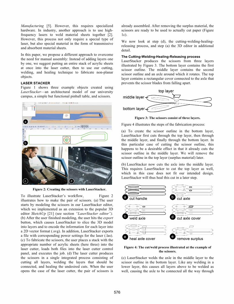
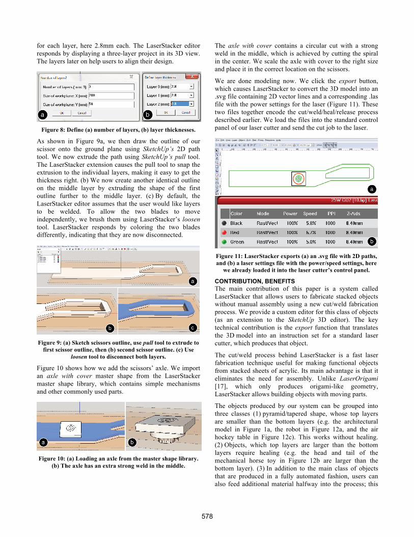
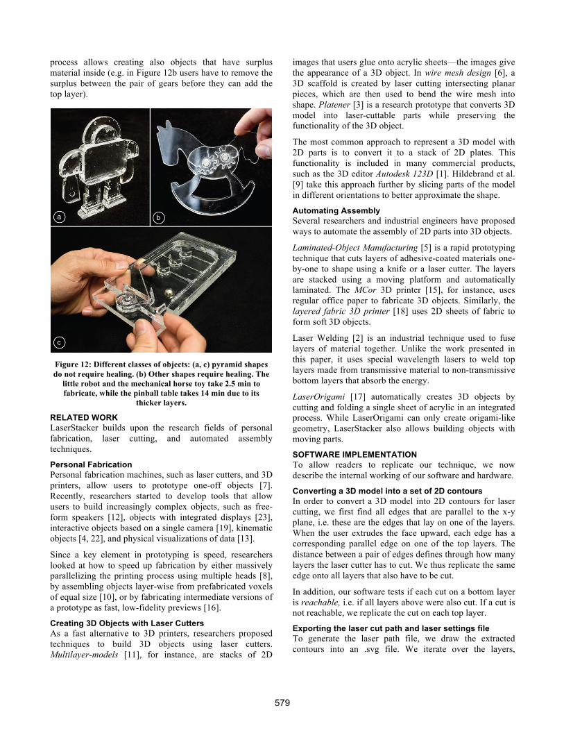
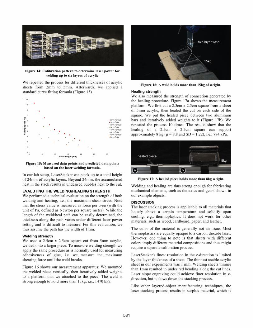


![Surround-See: Enabling Peripheral Vision on Smartphones ... › mkhasan › papers › 2013-UIST-khalad-Surro… · H5.2 [Information interfaces and presentation]: User Interfaces.](https://static.fdocuments.in/doc/165x107/5f1513cb7f75cb3bc23f4ee3/surround-see-enabling-peripheral-vision-on-smartphones-a-mkhasan-a-papers.jpg)