LaserNet Fines (LNF) - Particle Counting and Shape...
13
Page 1 of 13 160 Ayer Road Littleton, MA 01460 USA • Tel. (978) 486-0123 • Fax (978) 486-0030 • email:[email protected] • www.spectroinc.com LaserNet Fines (LNF) - Particle Counting and Shape Recognition for In-Service Oils Introduction Particle counting has long been recognized by maintenance professionals as an important tool to ensure new and in-service lubricant cleanliness. However, in most circumstances, particle counting is not applied to in-service oils as a wear monitoring tool. Particle counting is done mainly as a cleanliness check to in-service hydraulic oils, steam turbine oils and other applications in which wear is minimal . The particles counted in these relatively clean oils are usually assumed to be contaminant particles, not wear particles. In-service lubricating oils from other applications such as gears, transmissions and engines are typically not subjected to particle counting. The LaserNet Fines (LNF) was developed primarily to detect abnormal wear in samples containing high particle concentrations and samples that may be black from diesel engine soot. These are samples that are not conveniently monitored by conventional automatic particle counters. However, it is important to note that the LaserNet Fines was developed primarily not as a particle counter, but as a wear debris analyzer. It has the unique ability to recognize particle shape, classifying particles as sliding, cutting, fatigue, nonmetallic, fibers, droplets and air bubbles, thus providing guidance regarding the type of wear occurring within the machine from which the sample was taken. Coincidentally, the LNF also happens to be an accurate and reproducible particle counter. A Brief History of Particle Counting Filter Patch Method Before the invention and widespread use of automatic particle counters, particle counting was done by filtering the sample through a membrane filter and then manually counting particles using an optical microscope. This is often called the “Filter Patch” method, after the filter membrane used to capture particles from the sample. Some also call it the “Filter and Count” method, as this succinctly describes how it is done. There is some disparity in counts by the filter patch method due to variation between human practitioners, but differences may also result from differences between optical microscopes. It takes a rather high quality microscope to resolve particles down to 4 μm. Another big factor is that it is quite difficult to see partially transparent particles deposited on a milky looking membrane filter. This causes counts of small particles to be significantly under-reported. Automatic Particle Counters The large majority of existing automatic particle counters work on the principle of light blockage. The working principle is that an oil sample flows through a sensing chamber at a set
Transcript of LaserNet Fines (LNF) - Particle Counting and Shape...

Page 1 of 13
160 Ayer Road Littleton, MA 01460 USA • Tel. (978) 486-0123 • Fax (978) 486-0030 • email:[email protected] • www.spectroinc.com
LaserNet Fines (LNF) - Particle Counting and Shape Recognition for In-Service Oils
Introduction Particle counting has long been recognized by maintenance professionals as an important tool to ensure new and in-service lubricant cleanliness. However, in most circumstances, particle counting is not applied to in-service oils as a wear monitoring tool. Particle counting is done mainly as a cleanliness check to in-service hydraulic oils, steam turbine oils and other applications in which wear is minimal . The particles counted in these relatively clean oils are usually assumed to be contaminant particles, not wear particles. In-service lubricating oils from other applications such as gears, transmissions and engines are typically not subjected to particle counting. The LaserNet Fines (LNF) was developed primarily to detect abnormal wear in samples containing high particle concentrations and samples that may be black from diesel engine soot. These are samples that are not conveniently monitored by conventional automatic particle counters. However, it is important to note that the LaserNet Fines was developed primarily not as a particle counter, but as a wear debris analyzer. It has the unique ability to recognize particle shape, classifying particles as sliding, cutting, fatigue, nonmetallic, fibers, droplets and air bubbles, thus providing guidance regarding the type of wear occurring within the machine from which the sample was taken. Coincidentally, the LNF also happens to be an accurate and reproducible particle counter. A Brief History of Particle Counting Filter Patch Method Before the invention and widespread use of automatic particle counters, particle counting was done by filtering the sample through a membrane filter and then manually counting particles using an optical microscope. This is often called the “Filter Patch” method, after the filter membrane used to capture particles from the sample. Some also call it the “Filter and Count” method, as this succinctly describes how it is done. There is some disparity in counts by the filter patch method due to variation between human practitioners, but differences may also result from differences between optical microscopes. It takes a rather high quality microscope to resolve particles down to 4 µm. Another big factor is that it is quite difficult to see partially transparent particles deposited on a milky looking membrane filter. This causes counts of small particles to be significantly under-reported. Automatic Particle Counters The large majority of existing automatic particle counters work on the principle of light blockage. The working principle is that an oil sample flows through a sensing chamber at a set
Page 2 of 13
160 Ayer Road Littleton, MA 01460 USA • Tel. (978) 486-0123 • Fax (978) 486-0030 • email:[email protected] • www.spectroinc.com
flow rate. Light directed through the chamber is sensed by a quickly responding light sensor. Particles passing through the chamber reduce the light intensity in proportion to their size. In the late 1960’s a calibration procedure was developed to ensure that particle counts obtained with automatic particle counters agreed as closely as possible with counts obtained by optical microscopy. Air Cleaner Fine Test Dust (ACFTD) supplied by AC Rochester a division of GM was chosen to calibrate automatic optical particle counters and ultimately became International Standard ISO 4402. The ACFTD test dust size distribution was measured using a sieve and an optical microscope resulting in a size distribution based on maximum diameter. During the early 1990’s, with the application of more sophisticated scanning electron microscopes (SEM’s), it was noticed that there were actually many more particles in the ACFTD below 10 µm than had been previously reported in ISO 4402 using optical microscopy. Also in 1992, AC Rochester stopped the manufacture of ACFTD, As a consequence, the ISO standards committee together with the National Fluid Power Association (NFPA) decided to develop a revised particle counter calibration method based on a new contaminant whose distribution was traceable to NIST (National Institute of Standards and Technology). ISO Medium Test Dust1 (MTD) was selected and was suspended in MIL-H-5606 hydraulic fluid and became known as NIST Standard Reference Material SRM 28062.
Figure 1, Calibration Error, Instrument Calibrated with ACFTD vs. Calibration with ISO MTD.
There is a significant difference between the ACFTD and ISO MTD distributions, This can be shown when an automatic particle counter calibrated with ACFTD measures an ISO MTD as measured with a scanning electron microscope (Figure 1). The results show that below about 10 µm, NIST showed significantly more particles than with the ACFTD calibration. This can be explained because of the increased sensitivity of scanning electron microscopy compared to optical microscopy carried out in the 1960’s. As mentioned above, small translucent particles are very difficult to distinguish with a microscope against the
NIST vs ISO MTD
1
10
100
1000
10000
100000
1 10 100
Particle size µm
ISO 4402SEM (NIST)

Page 3 of 13
160 Ayer Road Littleton, MA 01460 USA • Tel. (978) 486-0123 • Fax (978) 486-0030 • email:[email protected] • www.spectroinc.com
opaque milky texture of a membrane filter. On the other hand, imaging by a SEM gives substance to these otherwise difficult to see small particles. The opposite occurs above 10 µm, fewer particles were observed by NIST compared to the ACFTD calibration. This is because the equivalent circular diameter used by NIST for its particle distribution is smaller than the maximum diameter used in the ACFTD, Figure 2.
Figure 2, Maximum Diameter vs. Equivalent Circular Diameter
ISO 11171 is now the industry standard calibration method for light blockage particle counters using NIST SRM 2806, Medium Test Dust in Hydraulic Fluid. The particle size distribution of this dust was carefully measured by NIST using scanning electron microscopy. As a practical matter, filter patch counting by optical microscopy consistently gives lower counts for small particles when compared to an automatic particle counter calibrated to ISO 11171 or to filter patch counting by SEM, or compared to the LaserNet Fines (LNF). Automatic particle counter errors may also occur if the sample flow rate varies from the calibration flow rate. If the flow rate increases, a given particle will block less light as it travels through the chamber and it will be reported as smaller than it actually is. Consequently, flow rate must be carefully controlled by an automatic particle counter even as viscosity varies. Errors may also occur because the particles in the calibration fluid are mostly transparent. Metal or other light blocking particles, for example coal dust, will appear larger than they are in actuality because they block more light than translucent particles. This may not be so important from the view point of trending when using automatic particle counters, but it confounds comparison when made to other methods, such as filter patch by SEM or LaserNet Fines (LNF). Lastly, errors may occur in automatic particle counters when the particle concentration becomes so high that 2 or more particles are present in the sensing chamber simultaneously. These
Maximum Diameter
Equivalent Circular Diameter (ECD) a
b
Note for long elongated particles a>b

Page 4 of 13
160 Ayer Road Littleton, MA 01460 USA • Tel. (978) 486-0123 • Fax (978) 486-0030 • email:[email protected] • www.spectroinc.com
Figure 3, LaserNet Fines®-C Particle Shape
Classifier and particle Counter
smaller particles are interpreted as one larger particle. This so-called “coincidence error” causes the number of small particles to be under-reported and the number of large particles to be over-reported. Depending upon the specific particle counter being used, coincidence errors begin around 10,000 particles/ml or at an ISO code of 21 (ISO Code 21 is 10,000 to 20,000 particles/ml). The coincidence error gets worse as particle concentration goes up. Automatic particle counting is very often applied to new oils or “clean’ oils such as hydraulic oils, but is often not applied to oils in the most demanding applications, such as engine oils or gear oils, where there is more thermal, chemical and mechanical stress on the lubricant that causes lubricant degradation and where there are significantly more wear and contaminant particles present. This is primarily because automatic particle counters are inadequate for sooted (diesel engine) oils or samples containing a high particle concentration. LaserNet Fines (LNF) A new type of optical particle counter, the LaserNet Fines3 (LNF), Figure 3, eliminates many of the errors of older counting technologies. LNF is a bench-top analytical instrument that combines the oil analysis techniques of particle shape classification and particle counting in one instrument. It analyzes hydraulic and lubricating oil samples from various types of equipment and machinery that are part of a machine condition-monitoring program. The monitoring is based primarily on the morphological analysis and the particle size distribution of the abnormal wear particles that are created from the internal components of the machine. The operator is presented with an assessment of particles found in the fluid sample and a history of previous results for the same equipment. The LNF can be used as a stand-alone analytical instrument, or in conjunction with a full service oil analysis program.
Lockheed Martin Tactical Defense Systems developed the LaserNet Fines in cooperation with the Naval Research Laboratory for the Office of Naval Research as part of its Accelerated Capabilities Initiative for Condition-based Maintenance. The original LNF instrument was designed as a stand-alone instrument in a rugged, shock and vibration protected case meant for shipboard use. This version is known as the LaserNet Fines-M (M for Military) and is no longer available. The LaserNet Fines-C (C for Commercial) is a reconfigured and more affordable version that uses an external computer for control and data storage. Sample processing, software and results are the same for both the LNF-C and LNF-M. Therefore, in this text, the instrument is referred to as the LNF, even though it is the LNF-C model that is now commercially available.

Page 5 of 13
160 Ayer Road Littleton, MA 01460 USA • Tel. (978) 486-0123 • Fax (978) 486-0030 • email:[email protected] • www.spectroinc.com
As a particle shape classifier, the LNF provides the user with shape recognition of all particles greater than 20 µm by using a neural network. An algorithm sorts particles into the following categories: cutting, fatigue, severe sliding, nonmetallic and fibers. The shape recognition software does a test for circularity so that bubbles and droplets greater than 20 µm are eliminated from the particle counting results. The instrument is also capable of giving approximate results of free water based on this feature.
As a particle counter, the LNF processes and stores thousands of images to obtain good counting statistics. Particles are sized directly and results can be displayed by ISO Code (>4 µm, >6 µm, and >14 µm), or other codes such as the NAS Code (5-15 µm, 15-25 µm, 25-50 µm, 50-100 µm and >100 µm). The direct imaging capability of this instrument eliminates the need for calibration with a test dust. Air bubbles greater than 20 µm are ignored and the laser is powerful enough to process heavily sooted (black) oils.
The basic operating principle of the LNF is illustrated in Figure 4. A representative oil sample is taken from the lubricating system and brought to the instrument. The oil is drawn through a patented viewing cell that is back-illuminated with a powerful short duration pulsed laser diode to freeze the particle motion. The coherent light is transmitted through the fluid and imaged onto a digital CCD camera. Each resulting image is analyzed for particles, with several thousand images ultimately used to determine the characteristics of the suspended particles and to obtain good counting statistics. Concentrations are measured for particle sizes between 4 µm to over 100 µm.
Figure 4, Basic Operation of LNF-C LNF reports particle size in terms of maximum chord (maximum diameter) and also calculates equivalent circular diameter for compatibility with ISO cleanliness codes. Shape characteristics are calculated for particles greater than 20 µm, and the particles are classified into either a wear category or contaminant category. Classification is done with an artificial neural network that was developed specifically for the LNF system. Shape features were chosen to give optimal distinction between the assigned classes of fatigue, cutting, severe sliding, nonmetallic, fibers, water bubbles, and air bubbles. An extensive library of particles, which were identified by
x4 Lens
CCD CHIP on LNF camera board640x480 PixelResolution
1.6mm
1.2mm
Flow Cell
10 μm
10 μm
Actual Pixel Resolution
PulsedLaser

Page 6 of 13
160 Ayer Road Littleton, MA 01460 USA • Tel. (978) 486-0123 • Fax (978) 486-0030 • email:[email protected] • www.spectroinc.com
human experts, was used to train the artificial neural network. An example of the shape classification capability of the LNF is shown in Figure 5.
The LNF was designed primarily as an automatic wear particle shape classifier and trending tool to assist in condition monitoring programs. However, because of its direct imaging capability it is also an accurate particle counter. It is ISO 4406:1999 compliant. The LNF does not require calibration using NIST Standard Reference Material (SRM) 28062 because it directly images the particles. During manufacture, magnification is calibrated to objects of known linear dimensions. Thereafter, periodic calibration is not required. This is unlike conventional particle counters and eliminates the costly requirement that the counter be periodically calibrated by ISO 11171, a procedure that many users find too difficult to perform themselves so they send their instruments back to the factory to have the work performed by qualified technicians. It is noteworthy that the LNF correctly counts the NIST SRM 2806 (or its derivative, the commercially available PartiStan). The NIST determined counts for SRM 2806 by capturing the particles from SRM 2806 hydraulic fluid on a membrane filter and counting the particles by using a scanning electron microscope (SEM). Particles appear solid when viewed by an SEM, even though the particles might be transparent to visible and near visible light. Therefore, a
Sliding WearSliding WearCutting WearCutting Wear
NonmetallicNonmetallicFatigue WearFatigue Wear
Figure 5, Shape Classification by the LNF

Page 7 of 13
160 Ayer Road Littleton, MA 01460 USA • Tel. (978) 486-0123 • Fax (978) 486-0030 • email:[email protected] • www.spectroinc.com
SEM fills in the area of particles that might otherwise be partially transparent when passing by the sensor of a conventional automated laser light blockage particle counter. Automated light blockage particle counters correctly measure SRM 2806 because this is the very fluid they are calibrated with. On the other hand, the LNF correctly measures the SRM 2806 because it is an automated microscope calibrated to a known linear dimension, a much more fundamental calibration than using an arbitrary calibration fluid. The LNF directly images each particle whereas an automated light blockage particle counter measures only how much light is blocked. In essence, the LNF achieves the same counts that the NIST did for the SRM 2806 from first principles. An automated light blockage particle counter gives no information about particle shape. A discrepancy may occur when comparing wear particle counts measured by an LNF with the counts from a conventional automated light blockage particle counter. The metal particles, being solid, will block more light proportional to their size than will transparent particles. Therefore, the light blockage particle counter will overestimate the size of metallic particles. The LNF imaging system captures digital images of the particles as they flow through the cell. The LNF fills in any translucent areas of fibers or nonmetallic particles that it may encounter in a sample, and calculates both the equivalent circular diameter and maximum diameter values for hydraulic cleanliness (ISO CODES) and wear particle trending, respectively. Because the LNF instrument records the total size resolution of all the particles that it records, it is able to report NAS and NAVAIR cleanliness codes. NAS 1638 was developed by the Aerospace Industries Association of America, and is similar to ISO 4406 in that it classifies cleanliness according to pre-defined particle counts of certain particle sizes. NAVAIR 01-1A-17 is the U.S. Navy standard for particulate cleanliness.

Page 8 of 13
160 Ayer Road Littleton, MA 01460 USA • Tel. (978) 486-0123 • Fax (978) 486-0030 • email:[email protected] • www.spectroinc.com
A suspension of test dust in oil such as NIST SRM 2806 may be measured by the LNF periodically to verify proper operation of the instrument, but the Standard Reference Material is never used to calibrate the LNF. A fluid check dialog is available, Figure 6, to show performance comparisons to certified NIST standards with cumulative graphical results.
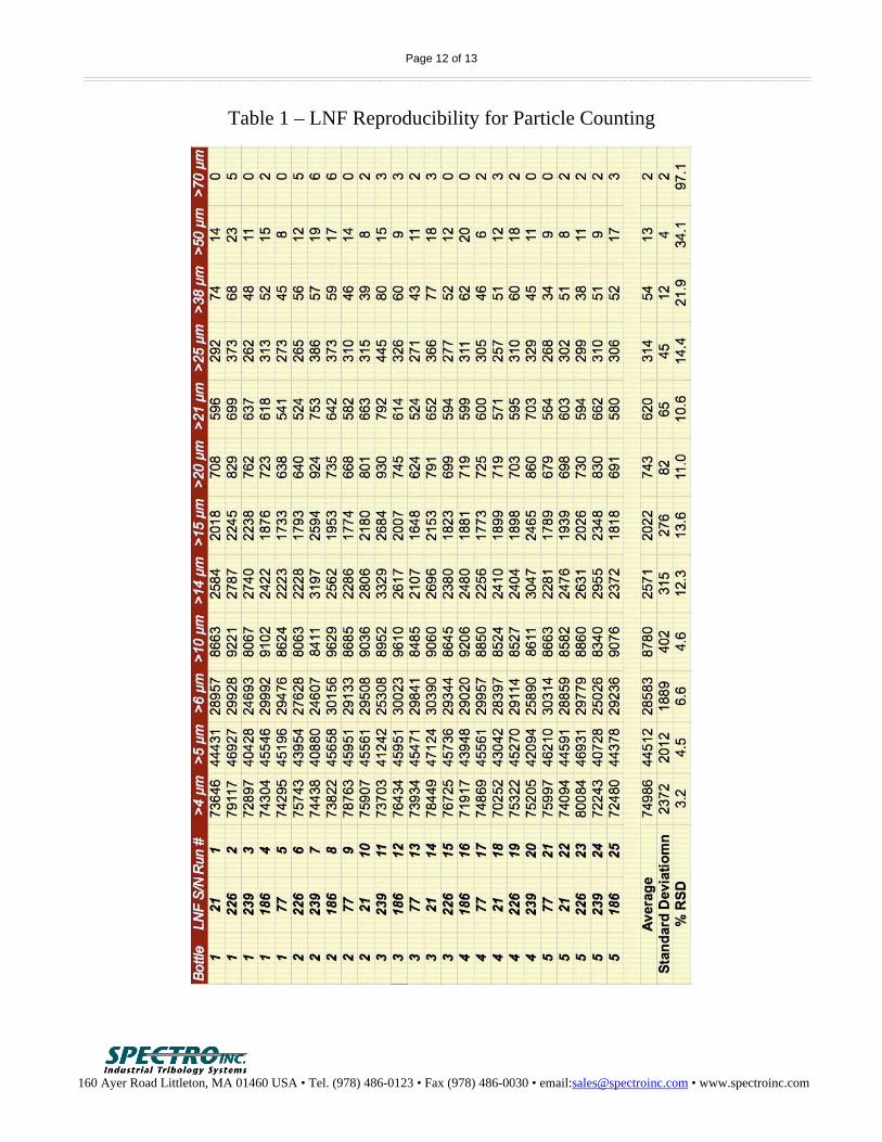
LNF Repeatability and Reproducibility The LaserNet Fines became commercially available in 2000 and since then about 250 instruments have been commissioned for various military and industrial applications in 41 countries around the world. Every LNF must successfully measure check fluid as described above, thus assuring that every LNF gives the same results. A test of LNF reproducibility has recently been performed4. Table 1 presents summary data. Test details may be found in Reference 4 including data showing good reproducibility for the particle shape recognition algorithms. Toward Better Particle Counting A recent survey5 described by Dr. Tim Nadasdi of ExxonMobil to the ASTM D02.CS96.5 subcommittee on particle counting for in-service lubricants found quite discrepant results when the same samples were submitted to various labs for counting either by automatic light blockage or filter patch, the two most widely applied particle counting methods. Some samples had differences of as much as 6 ISO codes, or a numerical factor difference of 26 = 64.
Figure 6, Calibration Verification Software Dialog

Page 9 of 13
160 Ayer Road Littleton, MA 01460 USA • Tel. (978) 486-0123 • Fax (978) 486-0030 • email:[email protected] • www.spectroinc.com
Not unexpectedly, among their observations they found that filter patch results were lower than automatic particle counter results. This doesn’t condemn filter patch counting as a trending tool, but it makes it problematic to compare filter patch counting to other counting methods. Perhaps more importantly, Dr. Nadasdi and his collaborators found the following factors cause inaccurate results:
- Sample handling and storage - Water - Air bubbles - Aggregated particles (i.e., agglomerates) - Particle coincidence (mentioned above) - Additive chemistry - Oil viscosity (presumably as it affects flow rate in an automatic light blockage particle
counter) Some comments about these factors are briefly discussed in the following paragraphs: Sample handling and storage – Taking a representative sample is an art in itself and beyond the scope of this article. However, it is often recommended that “clean” or “particle free” sample bottles be used. This seems obvious, but there is a practical way to use less than pristine bottles. Use the sample itself to clean the bottle by rinsing the sample bottle with the sample fluid two or three times, each time filling the sample bottle about halfway, screwing on the sample cap and shaking vigorously. Unless samples are run within a short time of being collected, they need to be agitated vigorously before they are run in order to thoroughly disperse particles that may have settled or agglomerated. Water – Water droplets will be counted as particles. When present, they can greatly increase particle counts. Water droplets may be dissolved by the correct choice of solvent. However, it should not be overlooked that the presence of water in certain samples is cause by itself for corrective action. The LNF recognizes water droplets, but only when they are > 20 µm. If there are large droplets present, there almost certainly will be many smaller ones and particle counts may be greatly increased by their presence. Air Bubbles – Air bubbles will be present after the sample has been vigorously shaken to thoroughly disperse particles. If left in the sample, they will vastly increase particle counts. Air bubbles may be removed by using an ultra-sonic bath. The bath must have sufficient power (power density > 4000 W/m2) to be efficient, especially for high viscosity samples. Vacuum degassing also works well. The LNF recognizes air bubbles, but only when they are > 20 µm. These larger air bubbles are removed from the count. However, if there are large air bubbles present, there almost certainly will be many smaller ones and particle counts may be greatly increased by their presence, as is the case for water droplets.
Page 10 of 13
160 Ayer Road Littleton, MA 01460 USA • Tel. (978) 486-0123 • Fax (978) 486-0030 • email:[email protected] • www.spectroinc.com
Agglomerates – These may be broken up by vigorous shaking. It may be helpful to agitate the sample in an ultra-sonic bath for 10 or 15 minutes. Particle Coincidence – Samples may be diluted with particle free oil for processing when particle concentration becomes too high for a given particle counter. This is somewhere around 10,000 to 50,000 particles/ml for automatic optical particle counters and around 5,000,000 particles/ml for the LNF. The LNF will give an error message when it encounters more particles than it can process. Most often, this is due to water droplets or other second phase fluids. If particle counts are this high due only to wear and contaminant particles, corrective action is indicated in any case. Additive Chemistry – Certain additives, in particular, polydimethylsiloxane, create so called “soft” or “phantom” particles. Tests done by Paul Michael and colleagues at the Fluid Power Institute at the Milwaukee School of Engineering6 confirmed that polydimethylsiloxane is the chief offender. Polydimethylsiloxane is a commonly used anti-foaming additive used primarily in engine oils. When added to base oil, these create small globules that get counted as particles by either automatic optical particle counters or the LNF. This has been causing considerable consternation primarily among heavy duty hydraulic system companies and clients. Often oils containing this anti-foaming additive are used and these oils have been failing cleanliness codes recommended by equipment suppliers. The largest polydimethylsiloxane globules get categorized as water droplets by the LNF because they have the same optical properties as water droplets. The smaller globules are counted as particles. Spectro Incorporated determined some years ago that adding various solvents such as hexane or toluene to the sample will dissolve these globules so that they are eliminated from the count. On-Going Work by the ASTM The aforementioned ASTM D02.CS96.5 subcommittee on particle counting is now working toward an ASTM method7 to prepare samples for particle counting so that interfering effects of water, phantom particles, air bubbles and agglomerates are eliminated. The goal is to establish a standard method such that automatic optical particle counters achieve reproducible results. It is intended that the LNF will be included in the round-robin testing to qualify this methodology so that precision and bias can be established for particle counting by the LNF compared to automatic optical particle counters. Separately, ASTM D02.96.7, the subcommittee on integrated testers, has initiated a work item for the LNF8. The LNF is considered an integrated tester because it does particle shape recognition, counts particles and measures soot. Much work yet needs to be done, but when round-robin testing is conducted, it is intended that in-service samples will include sooted (black) oils as well samples with high particle concentrations, samples that are not routinely run on automatic optical particle counters. Summary
The LNF is a new type of direct imaging particle counter offering the following features:

Page 11 of 13
160 Ayer Road Littleton, MA 01460 USA • Tel. (978) 486-0123 • Fax (978) 486-0030 • email:[email protected] • www.spectroinc.com
- intrinsically accurate particle counting - particle shape recognition - good reproducibility - soot measurement - ability to measure samples with very high particle concentration.
Page 12 of 13
160 Ayer Road Littleton, MA 01460 USA • Tel. (978) 486-0123 • Fax (978) 486-0030 • email:[email protected] • www.spectroinc.com
Table 1 – LNF Reproducibility for Particle Counting

Page 13 of 13
160 Ayer Road Littleton, MA 01460 USA • Tel. (978) 486-0123 • Fax (978) 486-0030 • email:[email protected] • www.spectroinc.com
References
1. ISO 12103-1, A3 Medium Test Dust, Analysis 5259M, 2 May 2005, Powder Technology, Inc., Burnsville, MN, USA.
2. Certificate of Analysis. SRM 2806a, National Institute of Standards and Technology (NIST), Gaithersburg, MD, USA.
3. J. Reintjes, R. Mahon, M.D. Duncan, L.L. Tankersley, J.E. Tucker, A. Schultz, V.C. Chen, C. Lu, T.L. McClelland, P.L. Howard, S. Raghavan and C.L. Stevens, “Real Time Optical Oil Debris Monitors”, in “A Critical Link: Diagnosis to Prognosis”, proceedings of the 51st Meeting of the MFPT, H.C. Pusey and S. Pusey, eds, pp. 443-448, 1997.
4. Spectro Inc., Product Information Document LNFC-08, “LaserNet Fines Reproducibility Test with Medium Test Dust”, available for download at www.spectroinc.com.
5. B. Koenitzer, C. Smith, A. Bolkhovsky and T. Nadasdi, “Oil Cleanliness and Particle Counting, Do We Really Know What We Are Measuring?”, Maintenance Technology, May 2007.
6. P.W. Michael, T.S. Wanke and M.A. McCambridge, " Additive and Base Oil Effects in Automatic Particle Counters", Journal of ASTM International, 2007, Vol. 4, No. 4, April, Paper Number JAI10094, 7 pp.
7. ASTM Subcommittee D02.96.5, Work Item 17832, “Automatic Particle Counting of Lubricating and Hydraulic Fluids Using Dilution Techniques to Eliminate the Contribution of Water and Interfering Soft Particles by Light Extinction”.
8. ASTM Subcommittee D02.96.7, Work Item 17748, “Automatic Particle Counting and Particle Shape Classification of Oils Using a Direct Imaging Integrated Tester”.


![LaserNet Manual TM0048 [RevAB]](https://static.fdocuments.in/doc/165x107/55cf9702550346d0338f3f87/lasernet-manual-tm0048-revab.jpg)