LaserAce Pocket Series Issue 1 - University of...
74
LaserAce® Pocket Series LaserAce ® Pocket Series Hand-held Reflectorless Instrument with Data Storage A WORLD LEADER IN LASER MEASUREMENT TECHNOLOGY CONTENTS PAGE 1 Quick User Guide 4 1.1 LaserAce® Survey............................................................................................................ 4 1.2 LaserAce® Hypsometer ................................................................................................... 7 2 Contact Information and Warranty 9 2.1 Dear Customer ................................................................................................................. 9 2.2 About this LaserAce® Pocket Series User’s Manual ..................................................... 10 2.3 Product Warranty ............................................................................................................ 11 2.4 Waste Information........................................................................................................... 11 3 Introduction 12 3.1 LaserAce® Pocket Series............................................................................................... 12 3.1.1 LaserAce® Survey Modes ........................................................................... 13 3.1.2 LaserAce® Hypsometer Modes................................................................... 13 3.2 Key Features .................................................................................................................. 13 4 Safety Information 15 4.1 Laser Safety.................................................................................................................... 15 4.2 Electromagnetic Compatibility and Emissions ............................................................... 16 4.3 Batteries .......................................................................................................................... 16 4.4 Hazardous Substances .................................................................................................. 16 5 Handling and Storage Precautions 17 5.1 Handling.......................................................................................................................... 17 5.2 Storage ........................................................................................................................... 17 5.3 Disposal .......................................................................................................................... 17 6 Overview of Applications 18 6.1 LaserAce® Survey.......................................................................................................... 18 6.2 LaserAce® Hypsometer ................................................................................................. 19 7 Preparation for use 20 7.1 Power Supply.................................................................................................................. 20 7.2 Hand-strap ...................................................................................................................... 21 7.3 Bluetooth® ...................................................................................................................... 22 7.4 Setup ..... 23 .......................................................................................................................... 7.4.1 Units ............................................................................................................. 24 7.4.2 Configuration................................................................................................ 25 7.4.3 Offsets .......................................................................................................... 30 7.5 Calibrating Compass ...................................................................................................... 33 Issue 1.0 © Copyright 1999-2008 Measurement Devices Limited Page 1 Copying of the materials in this document is prohibited
Transcript of LaserAce Pocket Series Issue 1 - University of...

LaserAce® Pocket Series
LaserAce® Pocket Series Hand-held Reflectorless Instrument with Data Storage
A W O R L D L E A D E R I N L A S E R M E A S U R E M E N T T E C H N O L O G Y CONTENTS PAGE
1 Quick User Guide 4 1.1 LaserAce® Survey............................................................................................................4 1.2 LaserAce® Hypsometer ...................................................................................................7 2 Contact Information and Warranty 9 2.1 Dear Customer .................................................................................................................9 2.2 About this LaserAce® Pocket Series User’s Manual .....................................................10 2.3 Product Warranty............................................................................................................11 2.4 Waste Information...........................................................................................................11 3 Introduction 12 3.1 LaserAce® Pocket Series...............................................................................................12
3.1.1 LaserAce® Survey Modes ...........................................................................13 3.1.2 LaserAce® Hypsometer Modes...................................................................13
3.2 Key Features ..................................................................................................................13 4 Safety Information 15 4.1 Laser Safety....................................................................................................................15 4.2 Electromagnetic Compatibility and Emissions ...............................................................16 4.3 Batteries..........................................................................................................................16 4.4 Hazardous Substances ..................................................................................................16 5 Handling and Storage Precautions 17 5.1 Handling..........................................................................................................................17 5.2 Storage ...........................................................................................................................17 5.3 Disposal ..........................................................................................................................17 6 Overview of Applications 18 6.1 LaserAce® Survey..........................................................................................................18 6.2 LaserAce® Hypsometer .................................................................................................19 7 Preparation for use 20 7.1 Power Supply..................................................................................................................20 7.2 Hand-strap ......................................................................................................................21 7.3 Bluetooth® ......................................................................................................................22 7.4 Setup .....23 ..........................................................................................................................
7.4.1 Units .............................................................................................................24 7.4.2 Configuration................................................................................................25 7.4.3 Offsets..........................................................................................................30
7.5 Calibrating Compass ......................................................................................................33 Issue 1.0 © Copyright 1999-2008 Measurement Devices Limited Page 1 Copying of the materials in this document is prohibited

LaserAce® Pocket Series
Issue 1.0 © Copyright 1999-2008 Measurement Devices Limited Page 2 Copying of the materials in this document is prohibited
8 Operation 35 8.1 Principle of Operation .....................................................................................................35 8.2 Usage..............................................................................................................................36 8.3 Switching On...................................................................................................................36 8.4 Key Selection..................................................................................................................37 8.5 Buzzer.............................................................................................................................37 8.6 Basic Instrument Functions ............................................................................................38 8.7 Switching Off...................................................................................................................38 9 LaserAce® Survey Menu Options 39 9.1 Rangefinder ....................................................................................................................39 9.2 Subtended Distance .......................................................................................................41 9.3 Missing Distance.............................................................................................................43 9.4 Area/Volume ...................................................................................................................45 9.5 Three Point Height..........................................................................................................46 9.6 Rapid Fire .......................................................................................................................48 10 LaserAce® Hypsometer Menu options 49 10.1 Rangefinder ....................................................................................................................49 10.2 Tree Diameter.................................................................................................................49 10.3 Length/Lean/Volume ......................................................................................................51
10.3.1 Single Point ..................................................................................................51 10.3.2 Two Point .....................................................................................................52 10.3.3 Three Point...................................................................................................55 10.3.4 Download .....................................................................................................59 10.3.5 Print Tree Table ...........................................................................................59 10.3.6 Clear Memory...............................................................................................59
11 Data Format 60 11.1 NMEA Output Format .....................................................................................................60 11.2 Format of Tree Measurement String ..............................................................................61 12 Bluetooth® on PC 62 12.1 Installing BELKIN® USB ‘Bluetooth®’ Adapter ..............................................................62 12.2 Troubleshooting ..............................................................................................................62 12.3 Running the ‘Bluetooth®’ Software for the First Time....................................................63 12.4 Configuring HyperTerminal to use ‘Bluetooth®’ Communications.................................63 13 Bluetooth® on Pocket PDA 64 13.1 Bluetooth® General ........................................................................................................64
13.1.1 Option 1: Use favourite ................................................................................64 13.1.2 Option 2: New search on connection...........................................................64
13.2 Bluetooth® on HP iPaq...................................................................................................65 13.2.1 iPaq Find new ..............................................................................................65
13.3 Recon luetooth® using Socket C.F. Card....................................................................66 B13.3.1 Search make favourite .................................................................................66 13.3.2 Bluetooth® Connection................................................................................68

LaserAce® Pocket Series
Issue 1.0 © Copyright 1999-2008 Measurement Devices Limited Page 3 Copying of the materials in this document is prohibited
14 Troubleshooting with Bluetooth® 69 14.1 PC Examples ..................................................................................................................69 14.2 PDA Examples................................................................................................................71 15 Technical Details 73 15.1 Specification ...................................................................................................................73 16 Notes 74

LaserAce® Pocket Series
Issue 1.0 © Copyright 1999-2008 Measurement Devices Limited Page 4 Copying of the materials in this document is prohibited
1 Quick User Guide
1.1 LaserAce® Survey
To start • Press the red ‘fire’ button on top of the instrument. The unit starts up confirming the unit type (ie.
Survey), date and version, and then Bluetooth® and compass • The main menu gives you a list of options/ or modes • To select a mode use the ▲ button, to enter that mode press the red fire button • The mode will ask you specific instructions • NOTE: To go back (at any time) press the ● button. Menu/ Setup • Firstly, you need to enter your offset height, which is the height from the ground to your eye level • Select ‘Setup’ • Within setup, select ‘3. Offsets’ (by using the ▲button) • Select ‘Instrument HT’ • Using the ■ button change the numbers. The ▲ button moves along the numbers • Press the red fire button to confirm • Press the ● button to go back to the main menu • YOU ARE READY TO GO. 1. Rangefinder • Select ‘1. Rangefinder’ mode by pressing the red fire button • The screen will show:
SD __________________________ m VA ___________________________°
HA ___________________________°
HA - COMPASS
• Point at your target and press the red fire button
VA 2.9°
HA 114.2°
HA - COMPASS
SD 18.08 m • Press the ▲ button to see horizontal distance and vertical distance.

LaserAce® Pocket Series
Issue 1.0 © Copyright 1999-2008 Measurement Devices Limited Page 5 Copying of the materials in this document is prohibited
2. Subtended Distance • The user looks through the sighting scope at the building.
You ‘bracket’ the stadia hairs (laser aiming and diameter scope) between the window frame (you do this by walking forward/ backwards until two fit either side of the object
• Press the red fire button (located on top) • The ‘diameter’ is given on the LCD screen. Make sure you
choose the correct ‘stadia hairs’ by clicking though the different pairs using the ▲ button.
3. Missing Distance • Select ‘3. Missing Distance’ • The LCD screen now shows:
STADIA NIL
TWO POINT SHOOT 1
• Follow the instructions. Note: LaserAce® Survey only measures missing distance in the vertical plane • The LCD screen now shows:
MISSING DISTANCE 2.75 GRADIENT 0.0m STADIA NIL
(example: height of internal wall) • Note: To go back (at any time) press the ● button. 4. Area/ Volume • Select ‘4. Area/ Vol’ • The LCD screen now shows:
2. RECTANGULAR AREA 3. TRIANGLE SURFACE AREA
AREA/ VOLUME 1. CONIC VOLUME
• Select ‘1. Conic Volume’ • The LCD screen now shows:

LaserAce® Pocket Series
Issue 1.0 © Copyright 1999-2008 Measurement Devices Limited Page 6 Copying of the materials in this document is prohibited
VOLUME OF CONE SHOOT THE BASE OF CONE
• Point and shoot at the base. It then asks you to ‘shoot the top of the cone’ • The LCD screen now shows: (example) • NOTE: To go back (at any time) press the ● button
• Select ‘2. Rectangular Area’ • The LCD screen asks you to enter
‘Instrument HT’. (If you did this at the start then ignore. If not follow instructions ▲ moves the cursor/ ■ changes the numbers). Press red fire button to confirm
• LCD screen now reads:
AREA OF RECTANGLE SHOOT LENGTH
• From your corner (as indicated in the diagram) shoot point ‘D’ – length • The screen now reads:
AREA OF RECTANGLE SHOOT BREADTH
• From your corner (as indicated in the diagram) shoot point ‘B’ – breadth • The screen now reads:
SUR. AREA 22.6m2 HOR. AREA 200.3m2
AREA OF RECTANGLE
LaserAce® Pocket Series
Issue 1.0 © Copyright 1999-2008 Measurement Devices Limited Page 7 Copying of the materials in this document is prohibited
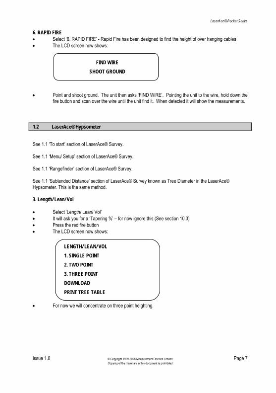
6. RAPID FIRE • Select ‘6. RAPID FIRE’ - Rapid Fire has been designed to find the height of over hanging cables • The LCD screen now shows:
FIND WIRE SHOOT GROUND
• Point and shoot ground. The unit then asks ‘FIND WIRE’. Pointing the unit to the wire, hold down the
fire button and scan over the wire until the unit find it. When detected it will show the measurements. 1.2 LaserAce® Hypsometer
See 1.1 ‘To start’ section of LaserAce® Survey. See 1.1 ‘Menu/ Setup’ section of LaserAce® Survey. See 1.1 ‘Rangefinder’ section of LaserAce® Survey. See 1.1 ‘Subtended Distance’ section of LaserAce® Survey known as Tree Diameter in the LaserAce® Hypsometer. This is the same method. 3. Length/ Lean/ Vol • Select ‘Length/ Lean/ Vol’ • It will ask you for a ‘Tapering %’ – for now ignore this (See section 10.3) • Press the red fire button • The LCD screen now shows:
DOWNLOAD PRINT TREE TABLE
3. THREE POINT
LENGTH/ LEAN/ VOL 1. SINGLE POINT 2. TWO POINT
• For now we will concentrate on three point heighting.

LaserAce® Pocket Series
Issue 1.0 © Copyright 1999-2008 Measurement Devices Limited Page 8 Copying of the materials in this document is prohibited
3. THREE POINT If scrub is an issue or leaves are fine at the top, three point heighting is idea. • Select ‘3. THREE POINT’ from the menu • For now keep Stadia NIL • Follow the instructions • The screen will show:
HD 4.66
THREE POINT TREE HT. 2.88
LaserAce® Pocket Series
Issue 1.0 © Copyright 1999-2008 Measurement Devices Limited Page 9 Copying of the materials in this document is prohibited
2 Contact Information and Warranty
2.1 Dear Customer
We would like to congratulate you on the purchase of your LaserAce® Pocket Series Instrument. You are now the owner of a high quality, personal laser surveying system. This instrument is easy to operate. However, we would ask you to take the time to carefully work though this users manual before using the instrument and keep the manual with the unit at all times. If your instrument requires a service, contact us at: UK USA Measurement Devices Ltd. Silverburn Crescent Bridge of Don Industrial Estate Aberdeen, AB23 8EW Scotland, UK Tel: + 44 (0) 1224 246 700 Fax: + 44 (0) 1224 824 987 email: [email protected] Web: http://www.mdl.co.uk
Western Data Systems (WDS) 14722 Regnal Street Houston Texas 77039 USA Tel: +1 (281) 987 2743 Fax: +1 (281) 987 1815 email: [email protected] Web: www.westerndatasystems.com
To enable us to give you our best help, please obtain the serial number, which can be found on the instrument. Thank you. Alternatively, for information on your nearest service and support centre visit our web site at http://www.mdl.co.uk
LaserAce® Pocket Series
Issue 1.0 © Copyright 1999-2008 Measurement Devices Limited Page 10 Copying of the materials in this document is prohibited
2.2 About this LaserAce® Pocket Series User’s Manual
Patent applied for. LaserAce® is a registered trademark of Measurement Devices Ltd. THIS MANUAL HAS BEEN COMPILED WITH CARE. HOWEVER, SHOULD YOU DISCOVER ANY ERROR, WE WOULD BE GRATEFUL IF YOU COULD CONTACT THE MARKETING DEPARTMENT DIRECT. [email protected] It is important that you read this manual carefully before using the instrument. Reproduction in whole or in part, including utilisation in machines capable of reproduction or retrieval, without the express written permission of MDL is prohibited. Reverse engineering is also prohibited. ©Copyright 2008 Measurement Devices Ltd. The programs that control this product are protected by copyright and all rights are reserved. Reproduction, adaptation, or translation of these programs without the express written permission of MDL is prohibited. All trademarks used in this manual are recognised. The information in this document is subject to change without notice. Manual Issue Status:
Date Issue Reviser 09/2008 1 ESB

LaserAce® Pocket Series
Issue 1.0 © Copyright 1999-2008 Measurement Devices Limited Page 11 Copying of the materials in this document is prohibited
2.3 Product Warranty
a) Unless otherwise specified, MDL warrants the equipment for a period of twelve months from date of delivery. This warranty is given subject to the following conditions:
I. MDL shall be under no liability in respect of any defects in the equipment arising from any
drawing, design or specification supplied or modification requested by the customer.
II. MDL shall be under no liability in respect of defects arising from fair wear and tear, wilful damage, negligence, abnormal working conditions, failure to follow MDL’s instructions (whether oral or in writing), misuse or alteration or repair of the equipment without MDL’s approval.
b) Claims in respect of defective equipment must be intimated by notice in writing to MDL and the equipment
must be retained by the customer pending written instructions from MDL. Following authorised return of the equipment, which must be made by the customer on a freight prepaid basis, MDL will examine the equipment. If the claim is justified, at MDL’s option, MDL will repair or replace the defective equipment without charge and MDL will have no further liability to the customer. 2.4 Waste Information
The crossed-out bin symbol, placed on the product, reminds you of the need to dispose of the product correctly at the end of its life. In this way you will assist in the recovery, recycling and reuse of many of the materials used in this product. Where possible recycle your packaging. With your help it is possible to reduce the amount of electrical and electronic waste ending up in landfill and to improve quality of life by preventing the release of potentially hazardous substances into the environment.

LaserAce® Pocket Series
Issue 1.0 © Copyright 1999-2008 Measurement Devices Limited Page 12 Copying of the materials in this document is prohibited
3 Introduction
LaserAce® Pocket Series comes in three versions: • LaserAce® Burden Finder, for measuring burden measurements in the Quarry market (separate
manual) • LaserAce® Survey, designed as a general survey tool, and • LaserAce® Hypsometer, specifically designed for foresters and arborists to aid in tree measuration. This manual is the users guide for: • LaserAce® Survey, or • LaserAce® Hypsometer. Most of the instructions for these are identical and where they differ the text is annotated accordingly or separate sections have been provided in this document. 3.1 LaserAce® Pocket Series
LaserAce® Pocket Series with built-in inclinometer and compass
LaserAce® Pocket Series is a hand-held laser range finder providing you with personal surveying capability. It enables the professional surveyor, engineer or general user to measure range, height, slope, missing distance, diameter, widths of objects and even cables with ‘point and shoot’ simplicity. LaserAce® Pocket Series incorporates a pulsed laser distance meter, inclinometer and compass. The sighting scope allows the operator to aim and measure range, vertical and horizontal angles to passive targets up to 150m (500’) away with 5cm (2”) accuracy. Using reflective foil the operator can measure to targets up to 600m (2000’) away. The palm-sized LaserAce® Pocket Series is Class 1 eye safe (FDA/ IEC) and weighs only 400g/ 14oz. Measurements and calculations are displayed on a custom back-lit LCD panel. Data output is available through Bluetooth® and can be configured to interface the LaserAce® to a range of data loggers, palm and pen computers.

LaserAce® Pocket Series
Issue 1.0 © Copyright 1999-2008 Measurement Devices Limited Page 13 Copying of the materials in this document is prohibited
3.1.1 LaserAce® Survey Modes
• Range finder (for measuring distances) • Subtended distance (diameter measurement) • Area and volume calculation • Three point heighting • Rapid fire mode for detecting cables. LaserAce® Survey does not incorporate a ‘save’ facility. These units have been designed for simple effortless use – point and shoot technology. There is no need for bulky accessories, targets or responders. It does it all in one single compact unit, affording users considerable cost savings on field operations. 3.1.2 LaserAce® Hypsometer Modes
• Brush filter mode (for use with reflective tape). Targeting specific trees • Critical range gating for area plots • Critical height and diameter detection • Heighting (with built in inclinometer) • 2-point height and lean measurement (also known as missing distance) • 3-point height measurement (for use when scrub and thin canopy are an issue) • Diameter measurement • Log volumes • Plot sampling • Range finder for measuring distances. LaserAce® Hypsometer incorporates a ‘save’ facility for storing data measurements of up to 2000 tree readings/ data sets. 3.2 Key Features
• Class 1 eye safe laser (FDA/ IEC) • 150m/ 500’ reflectorless range (no reflective target) • 600m/ 2000’ range with reflector • Accuracy 5cm/ 2” • Range resolution 1cm • Distance measurement in metres or feet • Angles in degrees/ gons • Low battery indicator and warning buzzer • Simply telescope sighting scope with integrated stadia hairs (x 5 magnification) • Bluetooth® data interface • Water and dust resistant (IP63) • Digital inclinometer range +/- 70°. Accuracy: 0.2° at level • 3-Axis solid state electronic compass with automatic pitch and roll correction (Electronically
Gimballed) Typical 2° Heading Accuracy with 1° Pitch and Roll Accuracy • Camcorder type rechargeable batteries (normal use 8hrs)(charger supplied) • Weight 400g/ 14oz • Size: 110mm L x 100mm W x 50mm H (4.33” L x 3.94” W x 1.97” H).

LaserAce® Pocket Series
Issue 1.0 © Copyright 1999-2008 Measurement Devices Limited Page 14 Copying of the materials in this document is prohibited
LaserAce® Pocket Series Features
Eye Piece Fire Button
Bluetooth® data download
Function keys
Transmitter and Receiver lenses
Removable and rechargeable battery
Backlit LCD display
Sighting Optics with Stadia hairs (x 5 magnification)
Hand Strap
LaserAce® Pocket Series
Issue 1.0 © Copyright 1999-2008 Measurement Devices Limited Page 15 Copying of the materials in this document is prohibited
4 Safety Information
4.1 Laser Safety
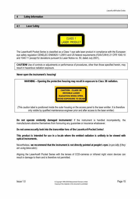
The LaserAce® Pocket Series is classified as a Class 1 eye safe laser product in compliance with the European eye safety regulation CENELEC EN60825-1 (2001) and US federal requirements (FDA/CDRH) 21 CFR 1040.10 and 1040.11 (except for deviations pursuant to Laser Notice no. 50, dated July 2001). CAUTION! Use of controls or adjustments or performance of procedures, other than those specified herein, may result in hazardous radiation exposure. Never open the instrument’s housing!
WARNING – Opening the protective housing may result in exposure to Class 3B radiation.
(This caution label is positioned inside the outer housing on the access panel to the laser emitter. It is therefore only visible by qualified maintenance engineer prior and after access to the laser emitter)
Do not operate evidently damaged instruments! If the instrument is handled incompetently, the manufacturers absolve themselves from honouring any guarantee or insurance whatsoever. Do not unnecessarily look into the transmitter lens of the LaserAce® Pocket Series! This product is intended for use in a locale where the emitted radiation is unlikely to be viewed with optical instruments. Nevertheless, we recommend that the instrument is not directly pointed at people’s eyes (especially if they are using binoculars). Aligning the LaserAce® Pocket Series with the lenses of CCD-cameras or infrared night vision devices can result in damage to them and is therefore not permitted.

LaserAce® Pocket Series
Issue 1.0 © Copyright 1999-2008 Measurement Devices Limited Page 16 Copying of the materials in this document is prohibited
4.2 Electromagnetic Compatibility and Emissions
The LaserAce® Pocket Series meets or exceeds the requirements of the following European Standards:
EN 55022: 1998 Limits and Methods of Measurement of Radio Interference Characteristics of Information Technology Equipment.
EN 55024: 1998 Information Technology Equipment – Immunity Characteristics – Limits and Methods of Measurement.
EN 55024 refers to the following specifications:-
EN 6100-4-2: 1995 Electromagnetic Compatibility Part 4. Testing and Measuring Techniques. Section 2. Electrostatic Discharge.
EN 61000-4-3: 1996 + A1 Electromagnetic Compatibility Part 4. Testing and Measuring Techniques. Section 3. Electromagnetic Field Immunity.
4.3 Batteries
Dispose of used batteries sensibly. Under no circumstances must the batteries (or instrument) be disposed of by burning. EXPLOSION MAY OCCUR! 4.4 Hazardous Substances
This product may contain substances that can be hazardous to the environment if not disposed of properly.

LaserAce® Pocket Series
Issue 1.0 © Copyright 1999-2008 Measurement Devices Limited Page 17 Copying of the materials in this document is prohibited
5 Handling and Storage Precautions
5.1 Handling
The LaserAce® Pocket Series is a reflectorless system. DO NOT USE reflectors at ranges below 100m, for ranges above 150m, reflectors may be employed. Note: DO NOT USE ‘LAST HIT’ Mode with reflectors. Avoid mechanical shock. Operate within the environmental temperature limits of –10°C to +45°C. Avoid directing the LaserAce® Pocket Series towards the sun or other high power, infrared light source. Do not use paint solvents to clean the instrument; use mild detergent applied using a cloth. 5.2 Storage
If the instrument remains unused for several weeks, it is advisable to remove the battery from the base of the instrument. Store within the environmental temperature limits of -25°C to +70°C. 5.3 Disposal
Electrical and electronic equipment should never be disposed of with general household waste but must be separately collected for their proper treatment and recovery. At the end of the life of your product the end-user may have an obligation to ensure that this Waste Electrical and Electronic Equipment (WEEE) is separately collected and to obtain and retain proof that it was handed to a waste management company who treated and disposed of it in an environmentally sound manner.

LaserAce® Pocket Series
Issue 1.0 © Copyright 1999-2008 Measurement Devices Limited Page 18 Copying of the materials in this document is prohibited
6 Overview of Applications
6.1 LaserAce® Survey
Hydrographic Survey
GIS Data Acquisition
Slope Gradient
• Agriculture Management • Asset Mapping • Building Surveys • Cable Height Measurement • GIS Survey • Gradient Measurements • Ground Modelling • Hydrographic Surveys • In-vehicle Surveying • Land Reclamation • Measurement of Pylons • Pipe Laying • Quarry Face Surveying (see LaserAce® Burden Finder) • Remote reconnaissance • Rock Face Profiling (see LaserAce® Burden Finder) • Rock Profiling • Utility Measurement.

LaserAce® Pocket Series
Issue 1.0 © Copyright 1999-2008 Measurement Devices Limited Page 19 Copying of the materials in this document is prohibited
6.2 LaserAce® Hypsometer
Forestry management and arboricultural surveys
Diameter (showing stadia scope)
Height measurement
Usin ing)g ‘Brush filter mode’ (reflect targets
2-point height and lean
3-Point height/diameter/volume in scrub Taper factor for volume and diameter

LaserAce® Pocket Series
Issue 1.0 © Copyright 1999-2008 Measurement Devices Limited Page 20 Copying of the materials in this document is prohibited
7 Preparation for use
7.1 Power Supply
An external 7.2V Lithium Ion ‘camcorder’ battery powers the instrument.
Note: The battery must be charged before use. A low battery indicator will show the power available from the battery, if it is not fully charged.
¾ Battery ½ Battery ¼ Battery Low Battery
When the battery reaches Low Battery status, the symbol will flash and a beeping noise will be heard. The unit will then display the screen as below, before switching itself off.
LOW BATTERY POWER
SWITCHING OFF

LaserAce® Pocket Series
Issue 1.0 © Copyright 1999-2008 Measurement Devices Limited Page 21 Copying of the materials in this document is prohibited
7.2 Hand-strap
1. Position unit and strap as shown.
2. Pass the strap into the Back Ring Mount until Hand Pad sits between both Ring Mounts.
3. Fold the Strap and insert it into the Hand Pad passing holes from left to right and through the Front Ring Mount.
LaserAce® Pocket Series
Issue 1.0 © Copyright 1999-2008 Measurement Devices Limited Page 22 Copying of the materials in this document is prohibited
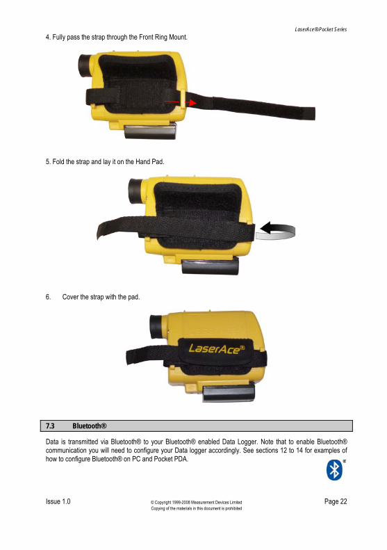
4. Fully pass the strap through the Front Ring Mount.
5. Fold the strap and lay it on the Hand Pad.
6. Cover the strap with the pad.
7.3 Bluetooth®
Data is transmitted via Bluetooth® to your Bluetooth® enabled Data Logger. Note that to enable Bluetooth® communication you will need to configure your Data logger accordingly. See sections 12 to 14 for examples of how to configure Bluetooth® on PC and Pocket PDA.

LaserAce® Pocket Series
Issue 1.0 © Copyright 1999-2008 Measurement Devices Limited Page 23 Copying of the materials in this document is prohibited
7.4 Setup
This is a representation of the setup menu screen, which can be accessed from the main menu screen.
From this menu you can change various parameters in the LaserAce® Pocket Series ie units such as range (metres/feet) and angles (degrees/gons) etc. See the following sections for more detail. To make a change to the LaserAce® Pocket Series press the ▲ key to scroll through the selections and then the FIRE key to make your selection.
LaserAce® Pocket Series
Issue 1.0 © Copyright 1999-2008 Measurement Devices Limited Page 24 Copying of the materials in this document is prohibited
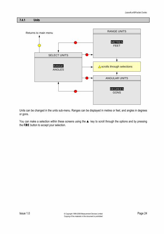
7.4.1 Units
SELECT UNITS
ANGLESRANGE
RANGE UNITS
FEETMETRES
ANGULAR UNITS
scrolls through selections
GONSDEGREES
Returns to main menu
Units can be changed in the units sub-menu. Ranges can be displayed in metres or feet, and angles in degrees or gons. You can make a selection within these screens using the ▲ key to scroll through the options and by pressing the FIRE button to accept your selection.
LaserAce® Pocket Series
Issue 1.0 © Copyright 1999-2008 Measurement Devices Limited Page 25 Copying of the materials in this document is prohibited
7.4.2 Configuration
The same key presses and flow apply to the configuration sub menu as for the units sub menu in the previous section. The user can make a selection within these screens using the ▲ key to scroll through the options and by pressing the FIRE button to accept the selection. The user can change the configuration of the LaserAce® Pocket Series by using the configuration sub menu within the Setup menu screen. Most of these are self-explanatory but particular attention should be paid to the Gradient, Ranging and Interface configuration options, and these are available depending on the type of LaserAce® Pocket Series equipment you have. GRADIENT (LaserAce® Survey) allows the user to select the way the gradient is displayed in missing distance mode. It can be displayed in Ratio Form, as an Angle or as a Percentage. RANGING Three choices exist in the Ranging menu; FIRST HIT, LAST HIT and ACTIVE MODE/ BRUSH FILTER. These can be useful under certain conditions. FIRST HIT, LAST HIT and ACTIVE MODE/ BRUSH FILTER See pages 27 and 28. ACTIVE MODE or BRUSH FILTER instructs the laser to only operate to active targets (reflective targets). The target to be used is a 150mm x 150mm piece of 3M reflective foil. The laser is NOT to be used to prisms in this mode, as the signal returned may be too strong and could lead to errors. This mode is provided to enable the laser to measure through obstructions (scrub, tree, brush) to the required point where the target has been positioned. The laser can operate through relatively dense obstructions but must be able to see at least part of the target. INTERFACE This is set at the MDL FREE FORMAT – do not change. For detailed information about the DATA FORMAT selection, see section 11 of this manual. POWER Power can be set as AUTO-POWER. ON or OFF.

LaserAce® Pocket Series
Issue 1.0 © Copyright 1999-2008 Measurement Devices Limited Page 26 Copying of the materials in this document is prohibited
Flowchart of LaserAce® Survey options
CONFIGURATION
GRADIENT RANGING
INTERFACE POWER
RANGING
FIRST HIT LAST HIT
ACTIVE MODE
GRADIENT
RATIO ANGLE
PERCENTAGE
INTERFACE
MDL FREE FORMAT MDL FIXED FORMAT
VARIANT FREE FORMAT VARIANT FIXED FORMAT
AUTO POWER
OFF ON
Return to setup menu

LaserAce® Pocket Series
Issue 1.0 © Copyright 1999-2008 Measurement Devices Limited Page 27 Copying of the materials in this document is prohibited
FIRST HIT is the ‘standard’ mode used for most types of operation where you have a clear sight of a target.

LaserAce® Pocket Series
Issue 1.0 © Copyright 1999-2008 Measurement Devices Limited Page 28 Copying of the materials in this document is prohibited
LAST HIT mode instructs the laser to return the last detectable hit in a multiple hit scenario. This mode is intended to help range through a limited type of single obstructions, such as wire fencing or glass. It is also a requirement that the distance between the initial obstruction and the ultimate target has to be several metres in order for a valid range to be calculated.
LAST HIT mode cannot be used with reflective targets or prisms nor used to calculate ranges to objects which have numerous obstructions in their path ie scrub, trees, brush, double glazing, etc.
/ BRUSH FILTER
ACTIVE MODE/ BRUSH FILTER mode instructs the laser to only operate to active (reflective) targets. The recommended target is a piece of 3M reflective foil (150mm x 150mm/6" x 6" at 100m range). The laser is NOT to be used to prisms in this mode as the signal returned may be too strong and could lead to errors. This mode is provided to enable the laser to measure through obstructions (scrub, tree, brush) to the required point where the target has been positioned. The laser can operate through relatively dense obstructions but must be able to see at least part of the target.

LaserAce® Pocket Series
Issue 1.0 © Copyright 1999-2008 Measurement Devices Limited Page 29 Copying of the materials in this document is prohibited
Flowchart of LaserAce® Hypsometer options
CONFIGURATION
RANGING
LAST HITBRUSH FILTER
FIRST HIT
INTERFACE
scrolls through selections
MDL FIXED FORMATVARIANT FREE FORMATVARIANT FIXED FORMAT
MDL FREE FORMAT
AUTO POWER
ONOFF
INTERFACEPOWER
RANGING
Returns to main menu
LaserAce® Pocket Series
Issue 1.0 © Copyright 1999-2008 Measurement Devices Limited Page 30 Copying of the materials in this document is prohibited
7.4.3 Offsets
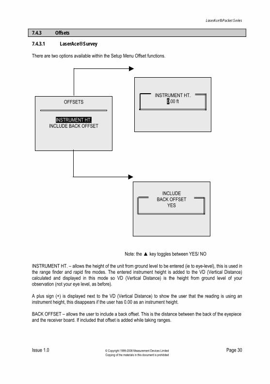
7.4.3.1 LaserAce® Survey There are two options available within the Setup Menu Offset functions.
INCLUDE
BACK OFFSET YES
OFFSETS
INSTRUMENT HT.
INCLUDE BACK OFFSET
INSTRUMENT HT. 0.00 ft
Note: the ▲ key toggles between YES/ NO INSTRUMENT HT. – allows the height of the unit from ground level to be entered (ie to eye-level), this is used in the range finder and rapid fire modes. The entered instrument height is added to the VD (Vertical Distance) calculated and displayed in this mode so VD (Vertical Distance) is the height from ground level of your observation (not your eye level, as before). A plus sign (+) is displayed next to the VD (Vertical Distance) to show the user that the reading is using an instrument height, this disappears if the user has 0.00 as an instrument height. BACK OFFSET – allows the user to include a back offset. This is the distance between the back of the eyepiece and the receiver board. If included that offset is added while taking ranges.

LaserAce® Pocket Series
Issue 1.0 © Copyright 1999-2008 Measurement Devices Limited Page 31 Copying of the materials in this document is prohibited
7.4.3.2 LaserAce® Hypsometer There are four options available within the Setup Menu Offset functions.
OFFSETS
CRITICAL HT.0.00 ft
INSTRUMENT HT.0.00 ft
USE CRITICAL HT.USE CRITICAL DIA.
OFFSETS
INSTRUMENTS HT.CRITICAL HT.
CRITICAL AREACRITICAL RADIUS
INSTRUMENT HT. – allows the height of the unit from ground level to be entered (ie to eye-level), this is used in the Range Finder mode. The entered instrument height is added to the VD (vertical distance) calculated and displayed in this mode so VD (vertical distance) is the height from ground level of your observation (not your eye level, as before). A plus sign (+) is displayed next to the VD (vertical distance) to show the user that the reading is using an instrument height, this disappears if the user has 0.00 as an instrument height.

LaserAce® Pocket Series
Issue 1.0 © Copyright 1999-2008 Measurement Devices Limited Page 32 Copying of the materials in this document is prohibited
CRITICAL HT
002.5 m/ft
Scrolls through unit selection
Increments units selected
The user is asked to use either Critical Height or Critical Diameter to sound alert in two point and three point height methods in length/lean/volume mode. The CRITICAL HEIGHT offset allows you to enter a height that the instrument will sound an alert once it has been reached. After recording the diameter and the bottom measurement as you move the instrument upwards the unit will beep once the critical height has been reached. Pressing the fire button again will complete the measurement. If CRITICAL DIAMETER is set to some non-zero positive value, once a diameter has been measured, using the tapering factor the LaserAce® unit calculates the height at which the critical diameter would be on the tree trunk. Hence as the user moves the instrument along the length of the tree, the unit beeps when the height corresponding to the critical diameter is reached. This way the LaserAce® Pocket Series can be used to measure tree logs with diameters not smaller than the critical diameter. The CRITICAL AREA & CRITICAL RADIUS options are interrelated, ie when one gets changed, the other gets updated as well. Critical area is a circular area within which the user might want to measure trees and not include any tree beyond the critical area with the Hypsometer positioned at the centre of the circular area. The corresponding radius is the Critical Radius; if the Critical Radius is set to any value (other than zero) the laser will not range beyond Critical Radius. NOTE: Critical Radius cannot be greater than 199 metres to limit excessively large critical area.

LaserAce® Pocket Series
Issue 1.0 © Copyright 1999-2008 Measurement Devices Limited Page 33 Copying of the materials in this document is prohibited
7.5 Calibrating Compass
On acquiring a new LaserAce® Pocket Series, it is recommended that you complete the following calibration in order to remove any interference. Integrated within the LaserAce® Pocket Series is a compass system that includes firmware for heading computation and calibration for magnetic distortions. The module combines 3-axis magneto-resistive sensors and 3-axis MEMS accelerometers, as well as other elements for heading computation. It is recommended that the user complete the following calibration routine in order to remove any further magnetic interference with the compass and its surrounding areas. USER CALIBRATION MAY BE NECESSARY IF THE BATTERY IS CHARGED OR REPLACED. Select ‘SETUP’ from main menu. Select ‘CONFIGURATION’ from setup menu. Select ‘COMPASS’ from configuration menu. Select ‘CALIBRATE’ from compass menu. Press a key to start calibration process. Calibration is a two-stage process, horizontal and downward calibration: • Start with eyepiece pointing towards the horizon, with device as level as possible • Press a key to start horizontal calibration. • Slowly rotate the Pocket Series clockwise through 360°. • Rotate at least twice, while maintaining level position. • Press a key to end the horizontal calibration process. Horizontal user calibration orientation.
LaserAce® Pocket Series
Issue 1.0 © Copyright 1999-2008 Measurement Devices Limited Page 34 Copying of the materials in this document is prohibited
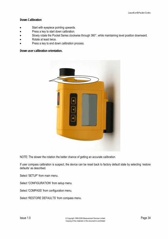
Down Calibration • Start with eyepiece pointing upwards. • Press a key to start down calibration. • Slowly rotate the Pocket Series clockwise through 360°, while maintaining level position downward. • Rotate at least twice. • Press a key to end down calibration process. Down user calibration orientation.
NOTE: The slower the rotation the better chance of getting an accurate calibration. If user compass calibration is suspect, the device can be reset back to factory default state by selecting ‘restore defaults’ as described. Select ‘SETUP’ from main menu. Select ‘CONFIGURATION’ from setup menu. Select ‘COMPASS’ from configuration menu. Select ‘RESTORE DEFAULTS’ from compass menu.

LaserAce® Pocket Series
Issue 1.0 © Copyright 1999-2008 Measurement Devices Limited Page 35 Copying of the materials in this document is prohibited
8 Operation
8.1 Principle of Operation
When the unit is operational and the FIRE button is pressed, invisible pulses are sent out from the LaserAce® Pocket Series transmitter lens and reflected pulses from the target are received via the instrument receiver lens. The time taken to send and receive the pulses is multiplied by the speed of light to determine the ‘two way’ distance. Half this distance is the correct ‘one way’ distance to the target. This is known as ‘The Time of Flight’ method. A target can be identified/acquired by sighting the target through the telescopic sighting scope. If a valid range or measurement is observed a built in BUZZER will automatically sound (long continuous sound). The maximum range observable can vary due to:
Centre of target
• Size of the target (with respect to the laser beam footprint) • Environmental conditions eg overcast/dark for longer ranges, but bright sunlight for shorter ranges • Rain or snow - shorter ranges. NOTE: Avoid shooting targets in the direction of the sun. Damage may occur to the receiver optics if pointed directly at the sun. The custom designed LCD is fitted with a sensor, which allows the instrument to automatically illuminate in poor lighting conditions. A few helpful tips to enable optimum ranges to be obtained are: • Good reflective targets include:
Light coloured rocks, traffic signs and vehicle reflectors, reflective foils, light coloured masonry and light coloured stone. NOTE: DO NOT USE ‘LAST HIT’ Mode with reflectors
• Try to observe targets that are in the shade or away from prevailing sunlight • Ideal target size is the same, or larger than, the LaserAce® beam footprint.
Laser Footprints at Various Ranges are given below.
Distance Typical Dimension of the Measuring Beam (footprint) 100m 25cm 200m 50cm 300m 75cm 400m 100cm
LaserAce® Pocket Series
Issue 1.0 © Copyright 1999-2008 Measurement Devices Limited Page 36 Copying of the materials in this document is prohibited
8.2 Usage
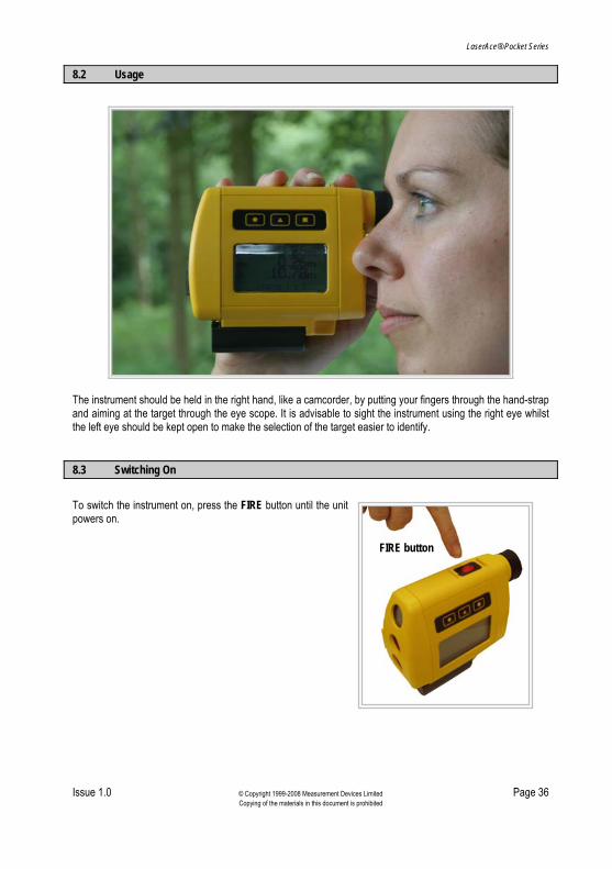
The instrument should be held in the right hand, like a camcorder, by putting your fingers through the hand-strap and aiming at the target through the eye scope. It is advisable to sight the instrument using the right eye whilst the left eye should be kept open to make the selection of the target easier to identify. 8.3 Switching On
To switch the instrument on, press the FIRE button until the unit powers on.
FIRE button

LaserAce® Pocket Series
Issue 1.0 © Copyright 1999-2008 Measurement Devices Limited Page 37 Copying of the materials in this document is prohibited
8.4 Key Selection
The LaserAce® Pocket Series has been designed to be easy to use. With that in mind, the key selection has been kept as consistent as possible within each mode/function of the instrument. In general the keys are used to perform the following actions. FIRE: Takes a reading/makes a selection.
Refer to sections 9 (Survey) or 10 (Hypsometer) for further information on what each key press does within each function of the LaserAce® Pocket Series. 8.5 Buzzer
The buzzer in the instrument has been programmed to automatically sound when: • The FIRE Button is used • The keypad is pressed (configurable on/off from setup menu) • To confirm when a range/distance has been acquired • The unit is being switched off.
Takes the user back up a level/
cancels selection
Scrolls down through a menu/ toggles between raw data and
calculated data
Accesses accumulated data

LaserAce® Pocket Series
Issue 1.0 © Copyright 1999-2008 Measurement Devices Limited Page 38 Copying of the materials in this document is prohibited
8.6 Basic Instrument Functions
When the LaserAce® is switched on, a built in BUZZER will sound automatically and the LCD will display the MDL logo, the instrument and the revision number and date of the firmware.
MDL www.mdl.co.uk
LA (Survey or Hypsometer) V x.x DD/MM/YYYY
After approximately 3 seconds, the unit will display the following screens.
BLUETOOTH CONFIGURED
PLEASE WAIT
The unit will then proceed to the menu option screen (see sections 9 (Survey) or 10 (Hypsometer) onwards). PLEASE NOTE: The unit is designed so that it can be used with or without reflectors. When the unit is switched on, it will go through the start up screens and tell you what ranging method you are working in (ie FIRST HIT /LAST HIT /BRUSH FILTER) depending on the type of LaserAce® Pocket Series equipment you have. IMPORTANT: If the user has been carrying out work using the Brush Filter (Active mode) and turns the unit off, when it is next switched on it will restart in the Brush Filter mode. This may cause a problem if the operator does not remember that the unit was in the Brush Filter mode, as when the unit is first used again it will not measure to objects without reflectors. Select First Hit or Last Hit to resume reflectorless operations. The three keys on the side panel, ●, ▲ and ■ keys are for changing modes/features and displaying raw data or calculations from various functions within the LaserAce® Pocket Series. Refer to sections 9 (Survey) or 10 (Hypsometer) in detail for the functionality of these keys. 8.7 Switching Off
To switch the instrument off, press and hold the ● and ■ keys at the same time. The display will show SWITCHING OFF and a digit will count down from 5 to 0. If the keys are released before 0 is reached then the unit is returned to the screen where the keys were pressed. If ‘auto switch-off’ is activated, the instrument will switch off one minute after the last key press occurred.

LaserAce® Pocket Series
Issue 1.0 © Copyright 1999-2008 Measurement Devices Limited Page 39 Copying of the materials in this document is prohibited
9 LaserAce® Survey Menu Options
This is a representation of the initial menu screen for the Survey: From this menu you can select one of the 6 functions of the Survey or access the setup menu. See the following sections for more detail. To enter a specific function press the ▲ key to scroll down through the selections and then the FIRE key to make your selection. 9.1 Rangefinder
SD -------.-----m VA --------.---° HA ------.---°
HA - COMPASS
Method of Operation The opening screen shows SD (Slope Distance), VA (Vertical Angle) and HA (Horizontal Angle). To take a measurement, align the cross hairs in the scope with the required target and press the red FIRE button on the top of the instrument. Once the distance has been acquired a long BEEP is heard and the results displayed on the LCD. NOTE: If the range display shows SD ---.—and the unit does not give a beep (or a short sharp beep) after pressing the fire button, this indicates that the instrument has not been able to obtain a distance to the selected target. Try again.
The LCD displays the actual slope distance (SD) from the laser to the target and inclination (+/- VA) (a “-“ sign signifies an angle below the horizontal, as in -9.3°) from the horizontal. It also reads horizontal angle from North, as in 119.8°.

LaserAce® Pocket Series
Issue 1.0 © Copyright 1999-2008 Measurement Devices Limited Page 40 Copying of the materials in this document is prohibited
Distance measurement can be in metres or feet and the inclination in degrees or gons (refer to section 7.4 for user preferences). By pressing the ▲ key the HD (Horizontal Distance) to the target and VD (Vertical Distance) to the target will be displayed, along with HA (Horizontal Angle). Press the ▲ key again to return to the original SD and VA display. A “+” sign following VD (VD+) means an instrument height offset is added (your height from ground to eye level) to give the vertical distance of the target. If the instrument height offset in set up is set to zero, then the vertical height is the height of the target from the instrument level (it will not show the “+” sign). Note: From any screen pressing the ● key returns the instrument to the main menu. To take a new measurement, sight the target and press the FIRE button. This displays the opening screen containing SD (slope distance), VA (vertical angle) and HA (horizontal angle) information. Accumulators: If you wish to show an accumulation of data (Slope and HD) then in either screen press the ■ key, this displays a sum of all SD and HD values acquired. Press ■ key from the accumulator display to return to the previous screen.

LaserAce® Pocket Series
Issue 1.0 © Copyright 1999-2008 Measurement Devices Limited Page 41 Copying of the materials in this document is prohibited
Flow diagram
ACCUMULATORS
SLOPE
HD 108.56m115.81m
HD
VD+ 5.70m112.06m
SD
VA 2.9112.20m
Note, display will read:VD+ if offset is addedVD if no offset
Returns to main menu
o
HA 114.2°
VA 4.7° SD 14.36m
ACCUMULATORS SLOPE 14.36m HD 14.31m
VD 1.18m HD 14.36m
9.2 Subtended Distance
The subtended distance function allows you to measure the approximate width of an object (ie bridge span or tree width) using one observation. Method of Operation After selecting Subtended Distance from the main menu the LCD displays:
SUBT. _ _ . _ _ m DIST. VD _ _ . _ _ m HD _ _ . _ _ m
STADIA 0 & 1
LaserAce® Pocket Series
Issue 1.0 © Copyright 1999-2008 Measurement Devices Limited Page 42 Copying of the materials in this document is prohibited
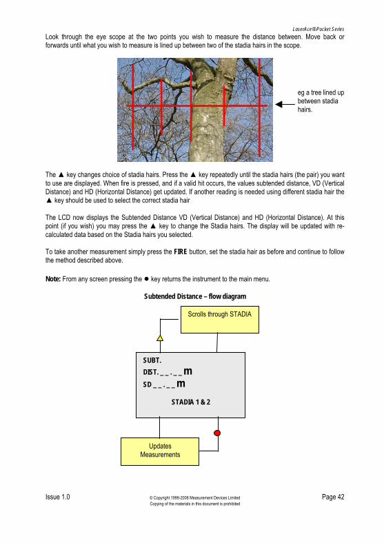
Look through the eye scope at the two points you wish to measure the distance between. Move back or forwards until what you wish to measure is lined up between two of the stadia hairs in the scope.
eg a tree lined up between stadia hairs.
The ▲ key changes choice of stadia hairs. Press the ▲ key repeatedly until the stadia hairs (the pair) you want to use are displayed. When fire is pressed, and if a valid hit occurs, the values subtended distance, VD (Vertical Distance) and HD (Horizontal Distance) get updated. If another reading is needed using different stadia hair the ▲ key should be used to select the correct stadia hair The LCD now displays the Subtended Distance VD (Vertical Distance) and HD (Horizontal Distance). At this point (if you wish) you may press the ▲ key to change the Stadia hairs. The display will be updated with re-calculated data based on the Stadia hairs you selected. To take another measurement simply press the FIRE button, set the stadia hair as before and continue to follow the method described above. Note: From any screen pressing the ● key returns the instrument to the main menu.
Subtended Distance – flow diagram
SUBT. DIST. _ _ . _ _ m SD _ _ . _ _ m
STADIA 1 & 2
Updates Measurements
Scrolls through STADIA

LaserAce® Pocket Series
Issue 1.0 © Copyright 1999-2008 Measurement Devices Limited Page 43 Copying of the materials in this document is prohibited
9.3 Missing Distance
Missing distance is used for remote calculation of height and distances between two or more successive points. This can be used for finding the heights of objects. The LaserAce® Survey will also calculate the gradient between the measured points.
Method of Operation After selecting missing distance from the main menu the LCD displays SHOOT 1 and the stadia hairs. In this mode the user can select which stadia hairs to measure the subtended distance between, along with measuring the missing distance between two points. After the first shot is taken the user is instructed to SHOOT 2. When the two shots have been taken, the missing distance between the two shots and the subtended distance (between the selected hairs) are displayed on the screen. NOTE: VERTICAL AND HORIZONTAL MISSING DISTANCE. Pressing the ▲ key displays the GRADIENT, HORIZONTAL DISTANCE and the HEIGHT DIFFERENCE between the points. The stadia hair selection can be NIL. In this case subtended distance is not calculated. Missing distance and gradient are displayed just after the second shot. Pressing the ▲ key displays horizontal distance vector and vertical distance vector between the points. To take another measurement press the FIRE button. Note that this does not take a reading and only returns the display to the SHOOT 1 screen. Press the FIRE button again to acquire the first measurement and continue as previously described above. Note: From any screen pressing the ● key returns the instrument to the main menu. Accumulators: Pressing the ■ key shows the accumulated missing distances. That is, it sums up all the previous missing distance measurements.

LaserAce® Pocket Series
Issue 1.0 © Copyright 1999-2008 Measurement Devices Limited Page 44 Copying of the materials in this document is prohibited
Missing Distance mode – flow diagram
SHOOT 2
Stadia 1 & 2
Missing Distance 1.17m Subtended Distance 0.02m
Stadia 1 & 2
TWO POINT Gradient 1:4.87 Horiz Dist 0.23m Height Difference 1.14m
Stadia 1 & 2
ACCUMULATORS
∑ Missing Distance
1.17m
SHOOT 1
Stadia 1 & 2
● Returns to main menu

LaserAce® Pocket Series
Issue 1.0 © Copyright 1999-2008 Measurement Devices Limited Page 45 Copying of the materials in this document is prohibited
9.4 Area/Volume
Area/Volume has three further sub options, these are: Conic Volume, Rectangular Area and Triangle Surface Area. Conic Volume The user is asked to SHOOT THE BASE OF CONE, and then SHOOT THE TOP OF CONE, in order to make measuring the volume of a cone from a distance easier. After the top point of the cone has been measured, the calculated volume is displayed. Pressing the ▲ key displays the cone height and radius at the base of the cone. Pressing the ■ key accumulates the calculated area. Rectangle Area The screen displays SHOOT LENGTH, and then SHOOT BREADTH. The user should stand at one corner of the rectangular area and shoot the other two adjacent corners. This mode is useful for measuring areas of land, eg a car park. The calculated area is displayed after the second shot. Pressing the ▲ key displays the length of the two sides of the rectangular area. Pressing the ■ key accumulates the calculated area. Triangle Surface Area The screen displays SHOOT SIDE A, B and C. The user can take measurements of two sides while standing at one vertex of the triangle and for the third side, the user has to be at one of the other two vertices. After the three shots have been taken, the area of the triangle is displayed on the screen. Pressing the ▲ key displays the length of the individual sides of the triangular area. Pressing the ■ key accumulates the calculated area.
LaserAce® Pocket Series
Issue 1.0 © Copyright 1999-2008 Measurement Devices Limited Page 46 Copying of the materials in this document is prohibited
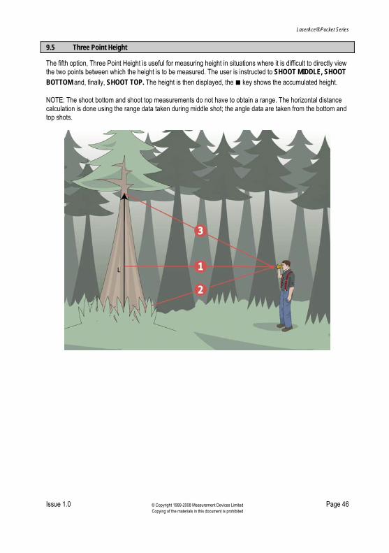
9.5 Three Point Height
The fifth option, Three Point Height is useful for measuring height in situations where it is difficult to directly view the two points between which the height is to be measured. The user is instructed to SHOOT MIDDLE, SHOOT BOTTOM and, finally, SHOOT TOP. The height is then displayed, the ■ key shows the accumulated height. NOTE: The shoot bottom and shoot top measurements do not have to obtain a range. The horizontal distance calculation is done using the range data taken during middle shot; the angle data are taken from the bottom and top shots.

LaserAce® Pocket Series
Issue 1.0 © Copyright 1999-2008 Measurement Devices Limited Page 47 Copying of the materials in this document is prohibited
THREE POINT
SHOOT MIDDLE
THREE POINT
SHOOT BOTTOM
THREE POINT
SHOOT TOP
THREE POINT
THREE PT. HT. 2.31m
ACCUMULATORS
∑ THREE PT. HT. 2.31m
LaserAce® Pocket Series
Issue 1.0 © Copyright 1999-2008 Measurement Devices Limited Page 48 Copying of the materials in this document is prohibited
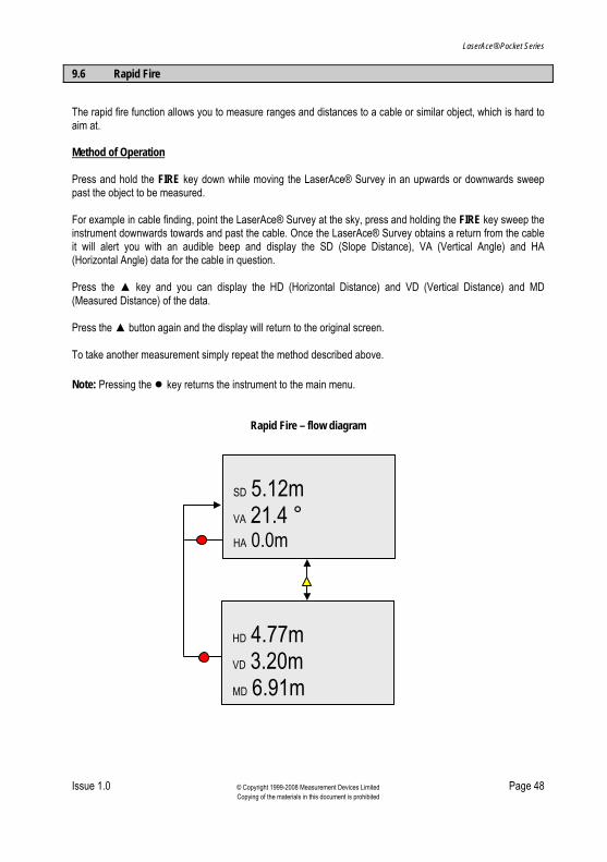
9.6 Rapid Fire
The rapid fire function allows you to measure ranges and distances to a cable or similar object, which is hard to aim at. Method of Operation Press and hold the FIRE key down while moving the LaserAce® Survey in an upwards or downwards sweep past the object to be measured. For example in cable finding, point the LaserAce® Survey at the sky, press and holding the FIRE key sweep the instrument downwards towards and past the cable. Once the LaserAce® Survey obtains a return from the cable it will alert you with an audible beep and display the SD (Slope Distance), VA (Vertical Angle) and HA (Horizontal Angle) data for the cable in question. Press the ▲ key and you can display the HD (Horizontal Distance) and VD (Vertical Distance) and MD (Measured Distance) of the data. Press the ▲ button again and the display will return to the original screen. To take another measurement simply repeat the method described above. Note: Pressing the ● key returns the instrument to the main menu.
Rapid Fire – flow diagram
SD 5.12m VA 21.4 ° HA 0.0m
HD 4.77m VD 3.20m MD 6.91m

LaserAce® Pocket Series
Issue 1.0 © Copyright 1999-2008 Measurement Devices Limited Page 49 Copying of the materials in this document is prohibited
10 LaserAce® Hypsometer Menu options
This is a representation of the initial menu screen for the Hypsometer: From this menu you can select one of the 3 function of the Hypsometer or access the setup menu. See the following section for more detail. To enter a specific function press the ▲ key to scroll through the sections and then the FIRE key to make your selection. 10.1 Rangefinder
Refer to section 9.1 in this document for the Rangefinder information. 10.2 Tree Diameter
The tree diameter function allows the user to remotely measure the diameter of a tree using one single measurement.

LaserAce® Pocket Series
Issue 1.0 © Copyright 1999-2008 Measurement Devices Limited Page 50 Copying of the materials in this document is prohibited
Method of operation After selecting Tree Diameter from the main menu, the LCD displays Set Tree Scope and Tree Scope 0 & 1. Aim the laser at the tree trunk and move back or forwards until the trunk is precisely enclosed between any two of the stadia hairs in the scope. Press ▲ key repeatedly until the tree scope hairs you want to use are displayed. Press the fire button to take the reading eg in the diagram above the display shows Tree Scope 1 & 3. Press the FIRE button to accept your choice of tree scope and take the reading.
The LCD now displays the tree diameter, VD (vertical distance) and HD (horizontal distance). As this point (if you wish) you may press the ▲ key to change the tree scope pairs. The display will be up dated with recalculated data based on the tree scope pairs selected. To take another measurement, press the FIRE button again. NOTE: When the fire button is pressed the tree scope choice selected is retained. To select a new tree scope choice, the ▲ key must be pressed again. From any screen, pressing the ● key returns the Hypsometer to the main menu. Flow diagram
SET TREE SCOPE
TREE SCOPE 0 & 1
DIAMETER
VD+
HD
--.--
--.--
--.--
Scrolls through Tree Scopes
Returns to main menu
TREE SCOPE 0 & 1

LaserAce® Pocket Series
Issue 1.0 © Copyright 1999-2008 Measurement Devices Limited Page 51 Copying of the materials in this document is prohibited
10.3 Length/Lean/Volume
As the name suggests this function allows measurement of tree length, lean and volume. The unit prompts for the Tapering factor to be entered first. The tapering factor, which depends on the species of tree to be measured, should be entered as a percentage. That is, a tapering factor of 10% implies that the tree diameter varies by 10cm for every 100cm in length. When the tapering factor is zero, the tree is considered to be in a cylindrical shape, with the tree diameter being taken from the middle shot. If the tapering factor is anything other than zero, then it is used to calculate the diameter of the top and bottom of the tree. The tree volume is calculated as volume of the frustrum with the top diameter being less than the diameter at the base of the tree. Once the tapering factor is entered, the Length/Lean/Volume menu is displayed, this has 6 sections: The first three are SINGLE POINT, TWO POINT and THREE POINT, which are the modes to measure and calculate tree length, lean and volume. The next two options are DOWNLOAD and PRINT TREE TABLE, for retrieving, printing and viewing the measurements saved in the unit’s memory. The last option CLEAR MEMORY, deletes the whole memory. Once the measured values have been calculated using any of the three methods, the calculated and measured data is sent out via Bluetooth® (refer to section 11.2). 10.3.1 Single Point
In the SINGLE POINT mode, the user is asked to SET DIAMETER SCOPE first. The stadia selection can be a stadia pair (eg 0 and 3) or it can be set to NIL. If stadia are set to NIL, only the log height and horizontal distance from the laser is measured. Pressing the ■ key after a shot accumulates the results. If the stadia scope is set to one of the stadia pairs, the user is asked to enter a plot number first, and then a tree number. The LaserAce® Pocket Series then searches the memory to see if this plot/tree number has already been entered, if the entry already exists then the user is asked if they wish to keep the stored entry or delete it. The screen then displays:
SINGLE POINT LOG DIAMETER - - . - - m. LOG HEIGHT - - . - - m. LOG VOLUME - - . - - m3
STADIA 0 & 2
The user should then sight the tree at the required diameter point on the trunk ensuring that the stadia hairs chosen “bracket” the tree and press Fire to take the reading. The Hypsometer then calculates the log diameter, height and volume. If tapering factor is set to zero, then the volume of the log is calculated as the volume of a cylinder. If the tapering factor is non-zero then this is used to calculate the base diameter and the volume is calculated as the volume of the frustrum. The ■ key accumulates log volume and log height (or only the log height if the stadia scope is set to NIL). NOTE: No volume calculation is done if the stadia scope is set to NIL.

LaserAce® Pocket Series
Issue 1.0 © Copyright 1999-2008 Measurement Devices Limited Page 52 Copying of the materials in this document is prohibited
10.3.2 Two Point
Two-point height is used for remote calculation of height and distance between two successive points. This is useful for finding the heights of trees and buildings. As in single-point mode, the user is asked to select the diameter scope first. If the stadia selected is NIL, the Hypsometer unit only calculates tree length and lean. The Hypsometer measures the gradient between measured points.
If using any value other than NIL on the diameter scope, the user will be asked to enter a PLOT NUMBER and a TREE NUMBER. The LCD then displays SHOOT BOTTOM. The first measurement should be taken at this time by pressing the FIRE button. The display will now show SHOOT TOP and the second measurement should be taken by pressing the FIRE button. The LCD will now display the following: • Log Length • Log Diameter • Log Volume. By selecting the ▲ button it will show the following: • Log Lean • Log Height • HD (Horizontal distance). NOTE: This is the distance from you to the object.

LaserAce® Pocket Series
Issue 1.0 © Copyright 1999-2008 Measurement Devices Limited Page 53 Copying of the materials in this document is prohibited
Pressing the ■ key after a shot accumulates the results. To take another measurement press the FIRE button and continue to follow the method described above. NOTE: From any screen pressing the ● key (continuously) will return the Hypsometer back to the main menu. Accumulators : If you wish to show an accumulation of data (Slope and HD) then in either screen press the ■ key, this displays a sum of all SD and HD values acquired. Press ■ key from the accumulator display to return to the previous screen. If using any value other than NIL on the stadia scope, the Hypsometer will, in addition to calculating log length and lean, also measure the log diameter and calculates the log volume. The first screen after shooting the top displays log length, log diameter and log volume. Pressing the triangle key displays log lean, height and hd (horizontal distance). The ■ key accumulates log volume and length. Critical height, which is entered in setup/offsets menu, is used in two-point height method. After shooting the bottom of the tree, the user pans (elevates) the unit to aim towards the tree top. If the critical height is reached while the user is moving the unit, the Hypsometer sounds continuously, this feature is useful if trees below a certain height are to be measured (refer to 7.4.3 to set Critical Height).

LaserAce® Pocket Series
Issue 1.0 © Copyright 1999-2008 Measurement Devices Limited Page 54 Copying of the materials in this document is prohibited
Flow diagram (using anything other than NIL on the stadia scope)
THREE POINT
PLOT NUMBER01
Log LengthLog DiameterLog volume
2.82m0.00m0.00m
STADIA 0 & 1
3
TREE NUMBER01
SHOOT BOTTOM
SHOOT TOP

LaserAce® Pocket Series
Issue 1.0 © Copyright 1999-2008 Measurement Devices Limited Page 55 Copying of the materials in this document is prohibited
10.3.3 Three Point
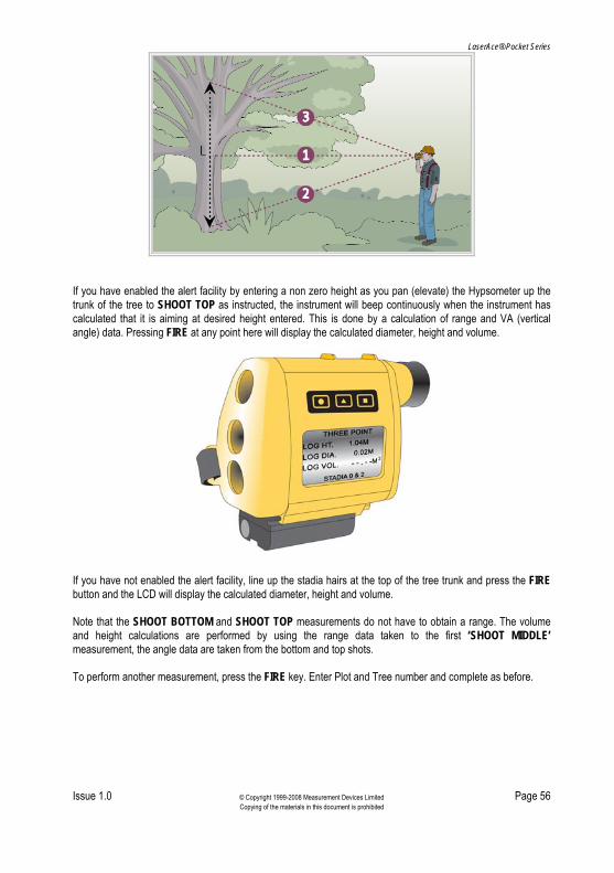
The three point method allows you to measure the diameter, height and volume of an object using three observations or enter a specific tree height and alert you to when that height has been reached (known as Critical Height). This mode calculates the diameter, height and volume based on one range and three measured angles. As in the previous two modes, the Diameter Scope selection can either be NIL or any one of the pairs.
Method of operation After selecting Three Point from the main menu the LCD displays SET DIAMETER SCOPE and STADIA NIL. If the diameter scope is set to one of the stadia pairs, the user is asked to enter the plot number first and then the tree number. The Tree Diameter Height mode has the facility to allow you to enter a specific height (eg a minimum desired log length). This length value should be entered and saved in the Set Up Menu – Offsets (see 7.4.3). When entered, Hypsometer will alert you (by continuous beeping) when you are aiming at the point on the tree when the height you have entered has been reached. This functionality is disabled by entering a height of 000.0. Look through the eye scope at the ‘mid point’ of the tree you wish to measure the diameter/height/volume of. Move back or forwards until the diameter you wish to measure is lined up between two of the stadia hairs in the scope. Press the ▲ key repeatedly until the stadia pairs you want to use are displayed eg using the diagram above until the display shows STADIA 1 & 3. Press the FIRE button to accept your choice of stadia pair. Enter the plot and tree number. The display now shows SHOOT MIDDLE. Line up the tree in the scope as before and press the FIRE button. You are now instructed to SHOOT BOTTOM. Use the scope to line up the stadia hairs at the bottom of the tree then centre the middle vertical stadia in the midpoint of the tree and press the FIRE button. At this stage the measurement of vertical angle only is required (not distance). This allows the observation to the bottom of the tree, even if scrub or brush partially obscures the view.
LaserAce® Pocket Series
Issue 1.0 © Copyright 1999-2008 Measurement Devices Limited Page 56 Copying of the materials in this document is prohibited
If you have enabled the alert facility by entering a non zero height as you pan (elevate) the Hypsometer up the trunk of the tree to SHOOT TOP as instructed, the instrument will beep continuously when the instrument has calculated that it is aiming at desired height entered. This is done by a calculation of range and VA (vertical angle) data. Pressing FIRE at any point here will display the calculated diameter, height and volume.
If you have not enabled the alert facility, line up the stadia hairs at the top of the tree trunk and press the FIRE button and the LCD will display the calculated diameter, height and volume. Note that the SHOOT BOTTOM and SHOOT TOP measurements do not have to obtain a range. The volume and height calculations are performed by using the range data taken to the first ‘SHOOT MIDDLE’ measurement, the angle data are taken from the bottom and top shots. To perform another measurement, press the FIRE key. Enter Plot and Tree number and complete as before.

LaserAce® Pocket Series
Issue 1.0 © Copyright 1999-2008 Measurement Devices Limited Page 57 Copying of the materials in this document is prohibited
Flow diagram (Tree Scope NIL)
THREE POINT
Scrolls through Tree ScopesSET DIAMETER SCOPE
STADIA NIL
THREE POINT
SHOOT MIDDLE
STADIA NIL
THREE POINT
SHOOT BOTTOM
STADIA NIL
THREE POINT
SHOOT TOP
STADIA NIL
Returns to main menu
THREE POINT
TREE HT. 11.27mHD 10.00m
STADIA NIL
Note : From any screen pressing the ● key returns the Hypsometer to the main menu.

LaserAce® Pocket Series
Issue 1.0 © Copyright 1999-2008 Measurement Devices Limited Page 58 Copying of the materials in this document is prohibited
Flow diagram (Stadia Pairs Selected)
THREE POINT
Scrolls through Tree Scopes
THREE POINT
SHOOT MIDDLE
STADIA 3 & 4
PLOT NUMBER01
THREE POINT
SET DIAMETER SCOPE
STADIA 3 & 4
THREE POINT
SHOOT BOTTOM
STADIA 3 & 4
THREE POINT
SHOOT TOP
STADIA 3 & 4
Returns to main menu
THREE POINT
LOG HT.LOG DIA.
LOG VOL.
1.32m0.55m0.31m
STADIA 3 & 4
THREE POINT
HD 10.51m
STADIA 3 & 4
TREE NUMBER01
3
Note : From any screen pressing the ● key returns the Hypsometer to the main menu.

LaserAce® Pocket Series
Issue 1.0 © Copyright 1999-2008 Measurement Devices Limited Page 59 Copying of the materials in this document is prohibited
10.3.4 Download
See sections 12 to 14 which give examples of how to configure Bluetooth® on PC or PDA. When entering this mode, the Hypsometer prompts the user to PRESS A KEY TO START, press any key to start the download procedure. Once the download has completed, the unit sounds a ‘beep’ and the message DOWNLOAD COMPLETE appears on the screen. All the entries in the memory are sent out as ASCII characters via Bluetooth® in the following format: PLOT NO., TREE NO., LENGTH m, DIAMETER m, VOLUME m, TAPER 10,10, 3.22, 0.03, 0.00, 0.00% 10,21, 3.17, 0.14, 0.05, 0.00% 10,22, 2.74, 0.15, 0.05, 0.00% 10,23, 2.69, 0.02, 0.00, 0.00% 10,24, 0.42, 0.04, 0.00, 0.00% The first string specifies the data fields in each line that follows (ie the first field in a line is the plot number, the next field is the tree number, etc with the last field being the tapering factor). This format is useful if the measured data is to be stored in a spreadsheet. You can use the Windows HyperTerminal application to view and record this data, if not familiar with this application follow the setup instructions described in section 12.4. To save the downloaded data to a file, first open HyperTerminal and connect to your instrument, then click the ‘Transfer’ menu then ‘Capture Text…’ enter an appropriate filename and click the ‘Start’ button. All serial data now sent to the PC will be saved in the specified text file. When complete, select the ‘Transfer’ menu, ‘Capture Text’ and ‘Stop’ option. 10.3.5 Print Tree Table
When entering this option, the user is asked to enter a Plot Number. Enter the number using ■ key and ▲key. Press FIRE key to enter. Then, using the ▲key, the user can select to either VIEW TABLE or PRINT TABLE for all the measured trees data of that plot number. Press the FIRE key to view or print the data.
T. (tree number) LEN. (length) DIA. (diameter) VOL. (volume) 10 3.22m 0.03m 0.00m3 21 3.17m 0.14m 0.05m3 22 2.74m 0.15m 0.05m3 23 2.69m 0.02m 0.00m3 24 0.42m 0.04m 0.00m3 25 2.59m 0.01m 0.00m3 26 3.66m 0.00m 0.00m3
***END*** 10.3.6 Clear Memory
Clear Memory wipes out all the data in the memory, but not before prompting the user that this is what they want to do (to prevent accidental deletion of the memory).

LaserAce® Pocket Series
Issue 1.0 © Copyright 1999-2008 Measurement Devices Limited Page 60 Copying of the materials in this document is prohibited
11 Data Format
11.1 NMEA Output Format
The data output via Bluetooth is in a standard NMEA format. IF1/3 is floating field and IF2/4 is fixed string length (note that in IF2/4 the range is restricted to 999.99m). See sections 12 to 14 for details of how to configure Bluetooth® on PC or PDA. Example data strings (note the strings are terminated with carriage return and line feed). IF1 $PMDLA,HV,2.94,M,288.1,D,8.6,D,2.98,M*5F IF2 $PMDLA,HV,002.94,M,288.1,D,008.6,D,002.98,M*67 IF3 Customer Variant Floating Field IF4 Customer Variant Fixed Field Data Output Formats are: FIELD DESCRIPTION RANGE
1 NMEA sentence type $PMDLA /Customer Spec.
2 Horizontal Vector HV
3 Horizontal Distance 2.94-5000.00/002.94
4 Units of measurement M (metres) F (feet)
5 Horizontal Angle 0.01-359.99 288.1
6 Units of Measurement D (degree)/G (gons)
7 Vertical Angle -0.1-080.0 -08.6
8 Units of measurement D (degree)/G (gons)
9 Slope Distance 2.98-5000.00 002.98
10 Units of Measurement M (metres)/F (feet)
11 Check Sum *67

LaserAce® Pocket Series
Issue 1.0 © Copyright 1999-2008 Measurement Devices Limited Page 61 Copying of the materials in this document is prohibited
11.2 Format of Tree Measurement String
Example of measurement string: $PMDLB,HT,004.40,M,DIA,001.06,M,VOL,003.87,M3,TAP,00.00%,R,020.22,M,V,015.1,D*61 Tree Measurement String Format:
Field Description Value
1 String Header $PMDLB
2 Tree Height HT
3 Measured Tree Height 004.40
4 Units of Measurement M(Metres) or F(Feet)
5 Tree Diameter DIA
6 Measured Tree Diameter 001.06
7 Units of Measurement M(Metres) or F(Feet)
8 Volume of Tree VOL
9 Measured Volume of Tree 003.87
10 Units of Measurement M3(cubic metres) or F3(cubic feet)
11 Tapering Factor TAP
12 Tapering Factor Value 00.00%
13 Range to the Tree (Slope Distance) R
14 Measured Range to the Tree 020.22
15 Units of Measurement M (Metres)
16 Vertical Angle to the Top of the Tree V
17 Measured Vertical Angle 015.10
18 Unit of Vertical Angle D (Degrees) or G (Gons)
19 Check Sum *61

LaserAce® Pocket Series
Issue 1.0 © Copyright 1999-2008 Measurement Devices Limited Page 62 Copying of the materials in this document is prohibited
12 Bluetooth® on PC
Whilst the following steps are interchangeable with most Bluetooth® connections, these guidelines are given in accordance with the BELKIN® device which the company can supply. 12.1 Installing BELKIN® USB ‘Bluetooth®’ Adapter
In order to download data from the LaserAce® Pocket Series, using BELKIN® Bluetooth® radio communication, the following steps must be followed. Also, please refer to hardware documents supplied. 1. The software drivers must be installed first, DO NOT insert the key into your PC at this point. 2. Place BELKIN® CD in drive. It should start automatically. 3. Answer YES to all questions and to default settings suggested unless there is good reason to do
otherwise. 4. The software will start loading. At some point a message will appear indicating that the software
cannot find a ‘Bluetooth®’ device. Press CANCEL to continue. 5. Once the software has finished loading remove the CD from the drive, insert the USB ‘Bluetooth®’ key
into a spare USB port on your PC. 6. Windows will recognise a new device and install the necessary drivers. 12.2 Troubleshooting
From this point, problems may occur, especially if your PC is running Windows XP and more so if it has Service Pack 2 installed. After Windows has shown that the ‘Hardware is ready to use’ check the system icons at the bottom right of your screen. There should only be one ‘Bluetooth®’ icon, probably with the ‘Bluetooth®’ symbol filled in, in red. If there are 2 icons then Windows has installed it’s own ‘Bluetooth®’ driver and the product will not function properly. To fix this do the following : 1. Open the Control Panel and select the System icon. 2. Click on the Hardware tab and select Device Manager. 3. The first item should be ‘Bluetooth® Devices’. Click on + sign next to this item. This will bring up 2
items ‘BELKIN® Bluetooth® Adapter’ and ‘Microsoft® Bluetooth® Enumerator’, the problem. 4. Right click on the BELKIN® Bluetooth® Adapter item and select Update Driver. 5. Select no, not at this time to the question whether Windows should find a driver. Click Next. 6. Click Install from a specific location (Advanced). Click Next. 7. Select Don’t search I will choose the driver to install. Click Next. 8. Click on the BELKIN® Bluetooth® Adapter item to highlight it and select Have Disk. 9. Select Browse and go to the directory C:\Progam Files\belkin\software\bin (assuming you selected
this default destination during installation). A filename will appear in the filename box, do not edit it. Click Open. On return to the window shown in 8. above. Repeat the process for the ‘BELKIN® Bluetooth® Device’. Once selected press Next.
10. This should complete installation and only one ‘Bluetooth®’ icon should now appear in the system icon tray at the bottom of the screen.

LaserAce® Pocket Series
Issue 1.0 © Copyright 1999-2008 Measurement Devices Limited Page 63 Copying of the materials in this document is prohibited
12.3 Running the ‘Bluetooth®’ Software for the First Time
Double click the My Bluetooth® Places icon on your computer desktop. This will guide you through selecting services for Bluetooth®. In the case where you only intend using the Bluetooth® to communicate with MDL’s laser products you should deselect all items except the Serial Port service. The software will then install the services you have selected. Once installed you may be asked for another profile. Click Skip then Finish or close the program. Double click on the My Bluetooth® Places icon again and right click on ‘my device’, select ‘properties’ Bluetooth® configuration should be shown. Click Client Applications tab. This shows a list of services provided by the ‘Bluetooth®’ adapter and particular shows the port to which Bluetooth® serial port communications have been mapped. Take a note of this, it maybe COMM 3 or COMM 5 depending on your system and how it is configured. When a new connection is established you will be prompted to enter a pass key, enter code ‘1, 2, 3, 4’. 12.4 Configuring HyperTerminal to use ‘Bluetooth®’ Communications
Items 1 to 8 below should only need to be done once and thereafter a short cut icon can be created to make easier access to Hyperterminal and the Bluetooth® communications to the laser. 1. Select the Hyper Terminal application by clicking the All Programs item in Windows START menu,
selecting Accessories and then Communications. 2. Select the HyperTerminal application. 3. HyperTerminal will start and display a ‘New Connection’ window. 4. Type in a name for the connection. ie ‘Bluetooth®’. 5. A ‘Connect To’ window will appear. Click the arrow next to the item ‘Connect Using’ and select the
COMM port shown in the ‘Bluetooth®’ configuration detailed above. 6. A window showing connection details will be displayed. These do not matter to ‘Bluetooth®’, just click
OK. 7. The Hyper Terminal window should clear awaiting communications. On this occasion click the File
item on the menu bar and select save. This saves the connection you may have named ‘Bluetooth®’. 8. Close Hyper Terminal. 9. Ensure the laser is switched on. 10. Repeat step 1 but this time an item showing Hyper Terminal with a sub menu will be shown. Go into
this sub-menu and an item with the name given in 4 above should be present. You can either use this method to quickly select Hyper Terminal with the ‘Bluetooth®’ settings detailed above or by placing the mouse pointer on the name and holding the left button and dragging it onto your desktop you can create a short cut.
11. A ‘Connected’ message should appear at the bottom left of the Hyperterminal window and the Bluetooth® icon in the toolbar at the bottom of the screen should change to green, showing a connection is active.

LaserAce® Pocket Series
Issue 1.0 © Copyright 1999-2008 Measurement Devices Limited Page 64 Copying of the materials in this document is prohibited
13 Bluetooth® on Pocket PDA
13.1 Bluetooth® General
An MDL LaserAce® Pocket Series transfers data by means of Bluetooth® Wireless communication. Once familiar with the set-up process it is simple use. The PDA on which you install your application must be Bluetooth® capable and activated for the application to function correctly. If you are familiar with Bluetooth® terminology you will know you have the ability to pair or store familiar Bluetooth® devices once configured, this saves time setting up communications between the two. 13.1.1 Option 1: Use favourite
If you set your LaserAce® Pocket Series to be a ‘favourite’ device in your Bluetooth® devices folder you will not have to search for new Bluetooth® devices whenever you connect. Your application can automatically establish communication with your LaserAce® Pocket Series. 13.1.2 Option 2: New search on connection
Do not create any favourite Bluetooth® devices on your PDA device, also do not set up the LaserAce® Pocket Series as a known Bluetooth® device on your PDA. When the your application needs to connect via Bluetooth® you will be prompted by a search screen. Select the LaserAce® Pocket Series that appears and communication will be established. This option has the advantage that it performs a new search every time you connect and re-confirms the Bluetooth® interface from the LaserAce® Pocket Series is within range and functioning.

LaserAce® Pocket Series
Issue 1.0 © Copyright 1999-2008 Measurement Devices Limited Page 65 Copying of the materials in this document is prohibited
13.2 Bluetooth® on HP iPaq
The MDL logger application requires your iPaq to have Bluetooth® assigned to a serial port.
Check that Serial interface over Bluetooth® function is enabled and has been assigned an outbound COM port number; take a note of this number.
13.2.1 iPaq Find new
Whenever you start your application you should be prompted to select a Bluetooth® device, as shown:
Firstly ensure the instrument is switched on and within range of your PDA, then either tap the Refresh button to initiate a new search of active devices or highlight an existing device from the list and tap Select to establish communications. If successfully connected you can now take readings and you will see the results shown on the screen, otherwise an error message will be shown.
Select Bluetooth® Settings
Click on the Bluetooth® icon
Scroll to Serial Port and take note of the Outbound COM Port

LaserAce® Pocket Series
Issue 1.0 © Copyright 1999-2008 Measurement Devices Limited Page 66 Copying of the materials in this document is prohibited
13.3 Recon Bluetooth® using Socket C.F. Card
To install a socket Bluetooth® card; follow the instructions supplied by the card manufacturer. Always install driver before inserting hardware card. Check that Serial interface over Bluetooth® function is enabled and has been assigned a COM port number; take a note of this number.
Click on the Bluetooth® icon
Select My Bluetooth® Device
Select COM Ports, take a note of the port number and confirm it is ticked.
13.3.1 Search make favourite
If you want to make your LaserAce® Pocket Series a Bluetooth® favourite, switch on the instrument, place it within range of the PDA and follow the instructions shown:
Tap the Bluetooth® icon Select Bluetooth® Devices Tap on the search icon

LaserAce® Pocket Series
Issue 1.0 © Copyright 1999-2008 Measurement Devices Limited Page 67 Copying of the materials in this document is prohibited
Wait until devices have
been found Tap Next Tap Next
Select a LaserAce Pocket Series then tap Next
Tap Finish
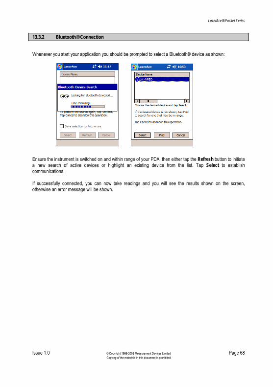
LaserAce® Pocket Series
Issue 1.0 © Copyright 1999-2008 Measurement Devices Limited Page 68 Copying of the materials in this document is prohibited
13.3.2 Bluetooth® Connection
Whenever you start your application you should be prompted to select a Bluetooth® device as shown:
Ensure the instrument is switched on and within range of your PDA, then either tap the Refresh button to initiate a new search of active devices or highlight an existing device from the list. Tap Select to establish communications. If successfully connected, you can now take readings and you will see the results shown on the screen, otherwise an error message will be shown.

LaserAce® Pocket Series
Issue 1.0 © Copyright 1999-2008 Measurement Devices Limited Page 69 Copying of the materials in this document is prohibited
14 Troubleshooting with Bluetooth®
If you are having problems connecting, the following sections give examples which solve common problems.
14.1 PC Examples
This screen is available with the Bluetooth® Advanced Configuration option and selecting ‘Local Services’ tab.
Select ‘Bluetooth® Serial Port’ and click ‘Properties’ button. Ensure ‘Secure Connection’ is ticked.
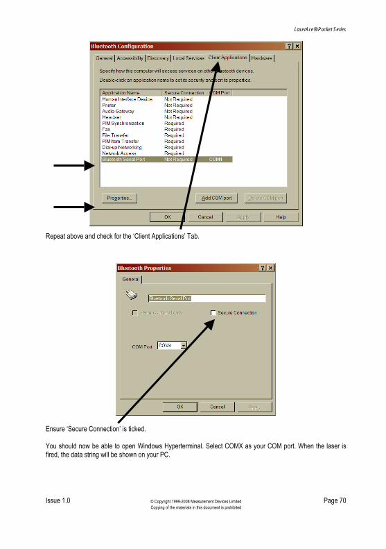
LaserAce® Pocket Series
Issue 1.0 © Copyright 1999-2008 Measurement Devices Limited Page 70 Copying of the materials in this document is prohibited
Repeat above and check for the ‘Client Applications’ Tab.
Ensure ‘Secure Connection’ is ticked. You should now be able to open Windows Hyperterminal. Select COMX as your COM port. When the laser is fired, the data string will be shown on your PC.

LaserAce® Pocket Series
Issue 1.0 © Copyright 1999-2008 Measurement Devices Limited Page 71 Copying of the materials in this document is prohibited
14.2 PDA Examples
Note: The following screen examples are taken from a PocketPC 2002 PDA fitted with Socket Bluetooth® Card. The procedures are similar to other PDA’s and card manufacturers.
Select ‘My Bluetooth® Device’ via the Bluetooth® Icon at the bottom of the screen and ‘Advanced Features’.
Ensure the ‘Use Authentication’ option is ticked.

LaserAce® Pocket Series
Issue 1.0 © Copyright 1999-2008 Measurement Devices Limited Page 72 Copying of the materials in this document is prohibited
Ensure a ‘Bluetooth® COM Port’ is ticked. You can now search for new Bluetooth® devices in the normal way and connect to your LaserAce® Pocket Series using MDL’s PDA Logger software.

LaserAce® Pocket Series
Issue 1.0 © Copyright 1999-2008 Measurement Devices Limited Page 73 Copying of the materials in this document is prohibited
15 Technical Details
15.1 Specification
Laser Type GaAs Laser Diode (905nm) Eye Safe Class 1 CENELEC EN60825-1/FDA Range Passive up to 150m/500’, Reflectors to 600m/2000’ Accuracy 5cm/2” Resolution 1cm Measurement Time 2 secs Environmental Operating Temperature -10° to +45°C Water and Dust Resistant IP63 Technical Construction Polycarbonate/ABS Dimensions (LxWxH) 110x100x50mm/4.33” x 2.94” x 1.97” Data I/O (when fitted) Bluetooth® Power 7.2V Lithium Ion battery Weight 400g/14oz Graphic LCD Display Backlit Alignment Telescope Telescopic eye scope with stadia hairs Inclinometer Type Accelerometer Range Pitch -70° to +70° Range Roll -20° to +20° Accuracy 0.2° at 0° Resolution 0.1° Compass Characteristics Conditions Typical Maximum Units Heading accuracy At level 2.0 3.0 +/- deg Heading Res Output data 0.1 - Degrees Tilt Range From horizontal +/- 70 - Degrees
Information contained herein is believed to be accurate. However, no responsibility is assumed by MDL for its use. Technical information is subject to change without notice.

LaserAce® Pocket Series
Issue 1.0 © Copyright 1999-2008 Measurement Devices Limited Page 74 Copying of the materials in this document is prohibited
16 Notes