Laser synchronization and timing distribution through a fiber network using femtosecond mode- locked...
53
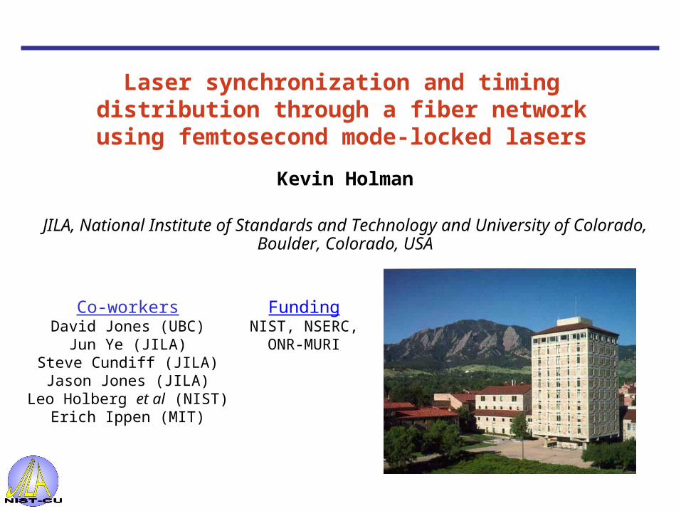
Laser synchronization and timing distribution through a fiber network using femtosecond mode-locked lasers Kevin Holman JILA, National Institute of Standards and Technology and University of Colorado, Boulder, Colorado, USA Co-workers David Jones (UBC) Jun Ye (JILA) Steve Cundiff (JILA) Jason Jones (JILA) Leo Holberg et al (NIST) Erich Ippen (MIT) Funding NIST, NSERC, ONR-MURI
-
date post
19-Dec-2015 -
Category
Documents
-
view
226 -
download
0
Transcript of Laser synchronization and timing distribution through a fiber network using femtosecond mode- locked...
Laser synchronization and timing distribution through a fiber network using femtosecond mode-
locked lasers
Kevin Holman
JILA, National Institute of Standards and Technology and University of Colorado, Boulder, Colorado, USA
Co-workersDavid Jones (UBC)
Jun Ye (JILA)Steve Cundiff (JILA)Jason Jones (JILA)
Leo Holberg et al (NIST) Erich Ippen (MIT)
FundingNIST, NSERC,
ONR-MURI

Desired in next generation light sources
• Synchronize X-rays with beamline endstation lasers for pump-probe experiments
• Synchronize accelerator RF with electron bunches
• Relative timing jitter of a few fs over ~1 km
Why Synchronization?
Master clocklaser + RF
Beamline endstation lasers
Linac RF
FEL seed lasers
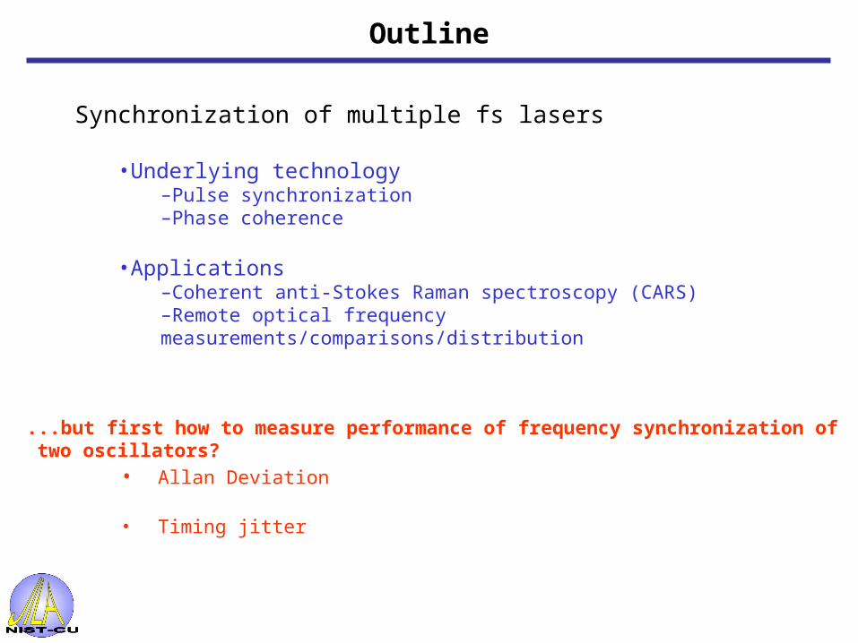
Synchronization of multiple fs lasers
•Underlying technology–Pulse synchronization–Phase coherence
•Applications–Coherent anti-Stokes Raman spectroscopy (CARS)–Remote optical frequency measurements/comparisons/distribution
...but first how to measure performance of frequency synchronization of two oscillators?
Outline
• Allan Deviation
• Timing jitter

Allan Deviation -typically used by metrology community as a measure of (in)stability-evaluates performance over longer time scales (> 1 sec or so)-can distinguish between various noise processes-indicates stability as a function of averaging time
Allan Deviation
4
56
10-12
2
3
4
5
All
an D
evia
tio
n
2 3 4 5 6 7 8 910
2 3 4 5
Averaging Time (s)
-20
-15
-10
-5
0
5
10
15
Fre
qu
ency
Dev
iati
on
s (H
z)
150100500 Time (sec)
Device Under Test
Master Oscillator Frequency Counter
Phase Lock Loop
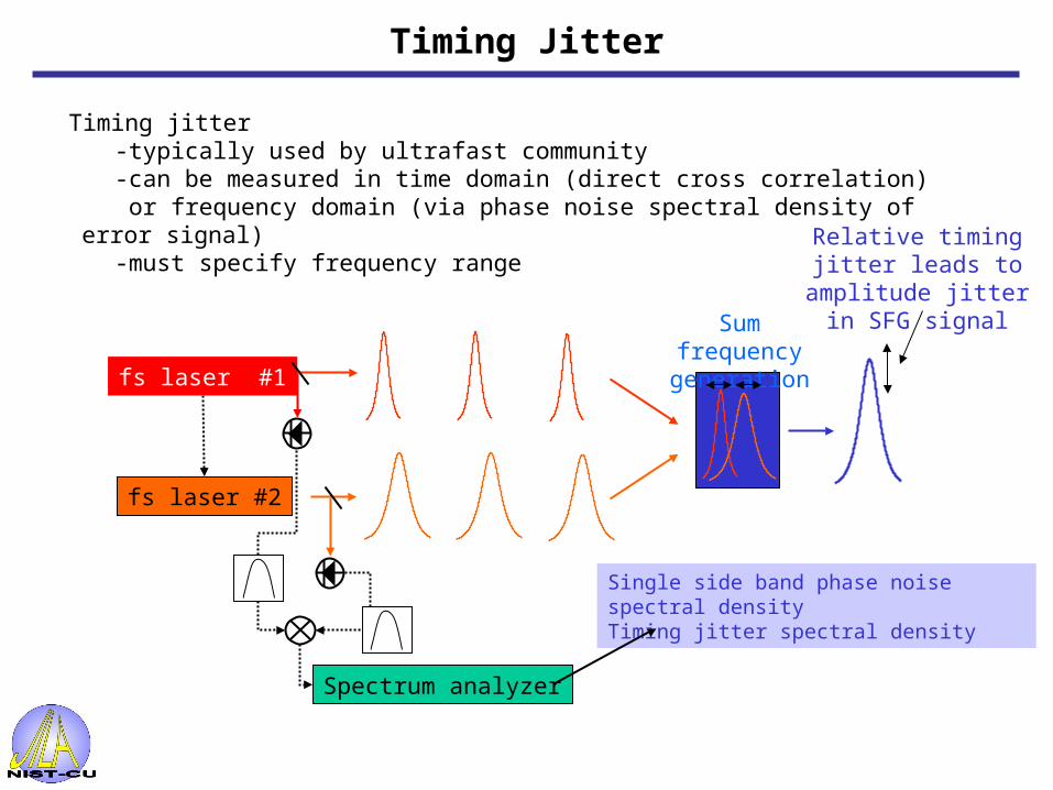
Timing jitter-typically used by ultrafast community-can be measured in time domain (direct cross correlation) or frequency domain (via phase noise spectral density of error signal)-must specify frequency range
fs laser #2
Sum frequency generation
Relative timing jitter leads to amplitude jitter in SFG signal
Spectrum analyzer
fs laser #1
Single side band phase noise spectral densityTiming jitter spectral density
Timing Jitter
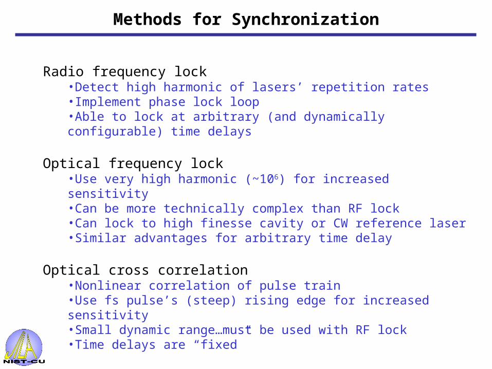
Radio frequency lock•Detect high harmonic of lasers’ repetition rates•Implement phase lock loop•Able to lock at arbitrary (and dynamically configurable) time delays
Optical frequency lock•Use very high harmonic (~106) for increased sensitivity•Can be more technically complex than RF lock•Can lock to high finesse cavity or CW reference laser•Similar advantages for arbitrary time delay
Optical cross correlation•Nonlinear correlation of pulse train•Use fs pulse’s (steep) rising edge for increased sensitivity•Small dynamic range…must be used with RF lock•Time delays are “fixed”
Methods for Synchronization

fs Laser 1
fs Laser 2
Laser 1repetitionrate control
100 MHz
50 ps
SHG
SHGBBO
SFG
SFGintensityanalysis
Phase shifter
14 GHz14 GHz
Phase shifter
14 GHz Loop gain
100 MHz Loop gain
Sampling scope
Delay
Experimental Setup for RF Locking
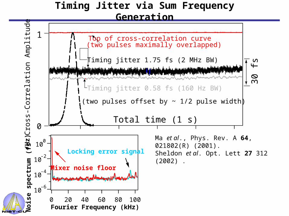
Timing jitter 0.58 fs (160 Hz BW)
Timing jitter 1.75 fs (2 MHz BW)
Top of cross-correlation curve
Total time (1 s)Cro
ss-C
orre
latio
n A
mpl
itude
30 fs
0
1(two pulses maximally overlapped)
(two pulses offset by ~ 1/2 pulse width)
Ma et al., Phys. Rev. A 64, 021802(R) (2001).Sheldon et al. Opt. Lett 27 312 (2002) .
No
ise
spec
tru
m (
fs2/H
z)
Fourier Frequency (kHz)
10-6
10-4
10-2
100
100806040200
Mixer noise floor
Locking error signal
Timing Jitter via Sum Frequency Generation
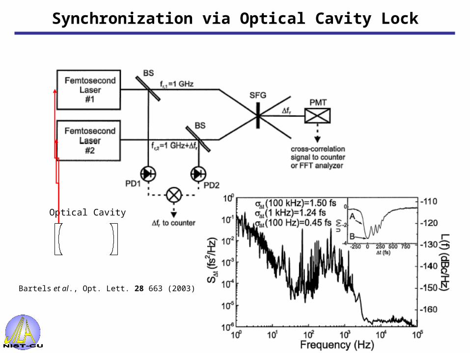
Bartels et al., Opt. Lett. 28 663 (2003).
Optical Cavity
Synchronization via Optical Cavity Lock

Output(650-1450nm)
Ti:sa
Cr:fo
3mm Fused Silica
SFG
SFG
Rep.-RateControl
(1/496nm = 1/833nm+1/1225nm).
Δt
0VSchibli et al Opt. Lett, 28, 947 (2003)
Synchronization via Optical Cross Correlation

Output(650-1450nm)
Ti:sa
Cr:fo
3mm Fused Silica
SFG
SFG
Rep.-RateControl
(1/496nm = 1/833nm+1/1225nm).
-
+
Δt
0V+GD
-GD/2
Δt
0V
Balanced Cross-Correlator
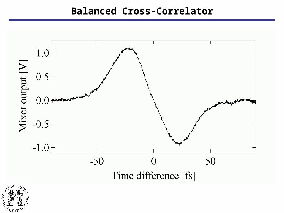
Balanced Cross-Correlator

Experimental result: Residual timing-jitter
The residual out-of-loop timing-jitter measured from 10mHz to 2.3 MHz is 0.3 fs (a tenth of an optical cycle)
1.0
0.8
0.6
0.4
0.2
0.0Cro
ss-C
orre
lati
on A
mpl
itud
e
-100 0 100
Time [fs]
100806040200Time [s]
Timing jitter 0.30 fs (2.3MHz BW)

Synchronization of two fs lasers
•Underlying technology–Pulse synchronization–Phase coherence
•Applications–Coherent anti-Stokes Raman spectroscopy (CARS)–Remote optical frequency measurements/comparisons/distribution
Outline cont…

Time domain
1/ frep =
t
E(t)
F.T. fofrep
Phase accumulated in one cavity round trip
Derivation details:Cundiff, J. Phys. D 35, R43 (2002)
D. Jones et. al. Science 288 (2000)I(f)
f
fo
n = n frep + fo
frep
Frequency domain
Time/Frequency Domain Pictures of fs Pulses

t
E(t)
For successful phase locking:
• Pulse repetition rates must be synchronized with pulse jitter << an optical cycle (at 800 nm << 2.7 fs)
• Carrier envelope phase must evolve identically (fo1=fo2)
1/ frep1 =
E(t)
fs laser
Pulse envelopes are locked
Evolution of carrier-envelope phases are locked
tfs laser
1/ frep2 =
fo2
I(f)
f
frep
fo1
Requirements for Coherent Locking of fs Lasers

fs Laser 1
fs Laser 2
Laser 1repetitionrate control
100 MHz
14 GHz14 GHz
50 ps
SHG
SHGBBO
SFG
Phase lock: fo1 -fo2 = 0
AOM
Phase shifter
Phase shifter
14 GHz Loop gain
100 MHz Loop gain
(Interferometric)Cross-CorrelationAuto-CorrelationSpectral interferometry
Sampling scope
Delay
Delay
Experimental Setup
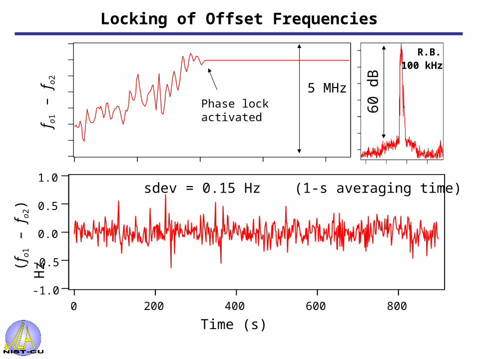
5 MHzPhase lock activated
R.B. 100 kHz
60 d
B
fo1
– f
o2
-1.0
-0.5
0.0
0.5
1.0
8006004002000
(f o
1 –
f o2)
H
z
Time (s)
sdev = 0.15 Hz (1-s averaging time)
Locking of Offset Frequencies
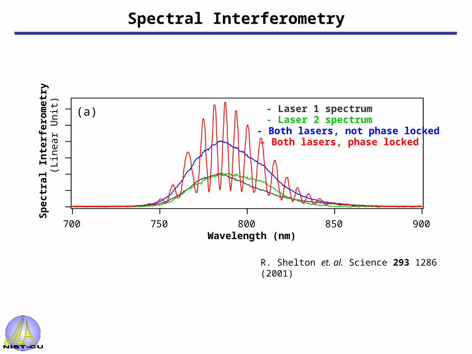
900850800750700
- Laser 1 spectrum- Laser 2 spectrum- Both lasers, not phase locked- Both lasers, phase locked
Sp
ec
tra
l In
terf
ero
me
try
(L
ine
ar
Un
it)
Wavelength (nm)
(a)
R. Shelton et. al. Science 293 1286 (2001)
Spectral Interferometry
Synchronization of two fs lasers
•Underlying technology–Pulse synchronization–Phase coherence
•Applications–Coherent anti-Stokes Raman spectroscopy (CARS)–Remote optical frequency measurements/comparisons/distribution
Outline cont…
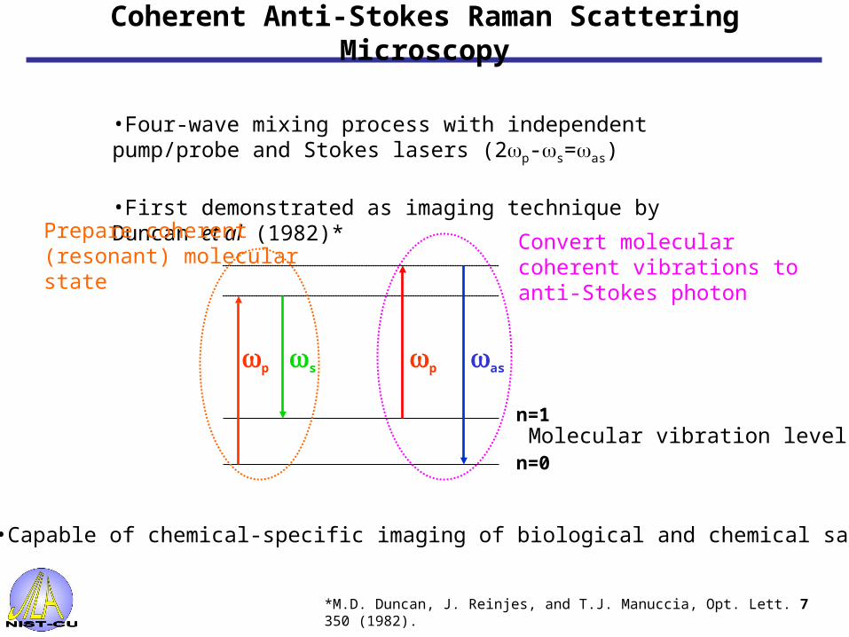
•Capable of chemical-specific imaging of biological and chemical samples
•Four-wave mixing process with independent pump/probe and Stokes lasers (2p-s=as)
•First demonstrated as imaging technique by Duncan et al (1982)*
Molecular vibration levels
Prepare coherent (resonant) molecular state
Convert molecular coherent vibrations to anti-Stokes photon
p assp
n=1
n=0
*M.D. Duncan, J. Reinjes, and T.J. Manuccia, Opt. Lett. 7 350 (1982).
Coherent Anti-Stokes Raman Scattering Microscopy
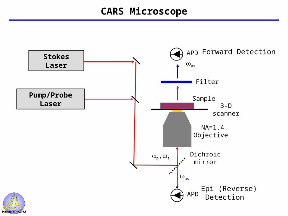
Dichroic mirror
as
p,s
3-D scanner
Sample
APD
Stokes Laser
Pump/Probe Laser
as
NA=1.4Objective
Filter
APD Forward Detection
Epi (Reverse) Detection
CARS Microscope

Stokes Laser (Master)
Pump/Probe Laser (Slave)
Feedback Loop
To CARSmicroscope
FFT Spectrum Analyzer
0.01
0.1
1
10
Am
pli
tud
e (
fs/H
z1/2
)
7 8 9
102
2 3 4 5 6 7 8 9
103
2 3 4 5 6 7 8 9
104
Frequency (Hz)
30
25
20
15
10
5
0
Jitte
r (fs)
locked unlocked total jitter
Jitter Spectral Density
Noise floor of mixer/amplifiers
100 MHz14 GHz
Lasers are Coherent Mira ps Ti:sapphire lasers
Synchronization Performance

BBO
SFG
14 GHz
Dichroic mirror
as
p,s
3-D scanner
APD
Bragg Cell
Bragg Cell
80 MHz14 GHz
Stokes Laser (Master)
Pump/Probe Laser (Slave)
PhaseShifter Phase
Shifter
14 GHz Loop gain
80 MHz Loop gain
DBM
DBM
Sum Frequency Generation (SFG)used to measure relative timing jitter
Bragg Cells usedto decimate rep. rate
Polystyrene beads in aqueous solution
Experimental Setup

1.0
0.5
0.0
-0.5
Re
lati
ve
Jit
ter
(ps
)
20151050T ime (sec)
1.2
1.0
0.8
0.6
0.4
0.2
CA
RS
In
ten
sit
y
20151050T ime (sec)
Pulse delay is adjusted to overlap at half-maximum point of cross-correlation
With 80 MHz lock, rms jitter is ~700 fs
Switching to 14GHz lock, rms jitter is 21 fs
Relative jitter via SFG
Bandwidth is 160 Hz
Relative jitter via CARS
StokesPump/Probe
SFGTiming jitter is converted to amplitude fluctuations
Relative Timing Jitter

Cou
nts
Cou
nts
100
0
100
0
80-MHz lock~770 fs timing jitter
2 m
14-GHz lock~20 fs timing jitter
Raman shift = 1600 cm-1
Pump 0.3 mW @ 250 kHzStokes 0.15 mW @ 250 kHz
Images of 1mm Diameter Polystyrene Beads

Synchronization of two fs lasers•Underlying technology
–Pulse synchronization–Phase coherence
•Applications–Coherent anti-Stokes Raman spectroscopy (CARS)–Remote optical frequency measurements/comparisons/distribution
Outline cont…

Synchronization of Remote Sources
Compare optical standards for tests of fundamental physics
Required in next generation light sources
• Synchronize X-rays with beamline endstation lasers for pump-probe experiments
• Synchronize accelerator RF with electron bunches
• Relative timing jitter of a few fs over ~1 km
Telecom network synchronization
• Low timing-jitter: dense time-division multiplexing
• Frequency reference from master clock allows dense wavelength-division multiplexing
Incr
easi
ng s
tabi
lity

Optical frequencystandard
fs Ti:sapphirecomb
Optical atomic clock
End user
Distribution of frequency standards
Optical fiber network
1.5-m transmittingcomb
End user End user
Optical standard
1/
RF standard
Holman et al. Opt. Lett. 28, 2405 (2003)Jones et al. Opt. Lett. 28, 813 (2003)
Degradation of signal during detection minimized
Noise added by fiber must be detected and minimized

JILA
NIST
Broadway
JILA
NIST
JILA
NIST
Broadway
L. HollbergC. Oates
Single Hg+ ion
J. BergquistD. Wineland
Trapped Sr
Iodine clock
BoulderRegionalAdministrativeNetwork
3.45 km fiber link between JILA and NIST
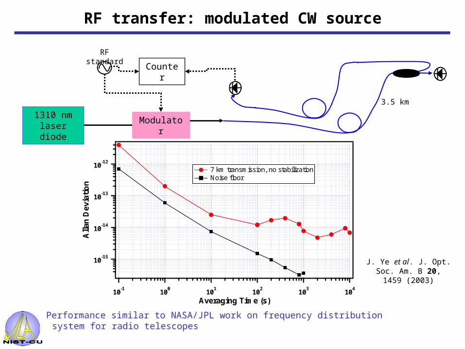
RF transfer: modulated CW source
1310 nm laser diode
RF standard
Modulator
3.5 km
Performance similar to NASA/JPL work on frequency distribution system for radio telescopes
J. Ye et al. J. Opt. Soc. Am. B 20, 1459 (2003)
Counter
10-15
10-14
10-13
10-12
All
an D
evia
tio
n
10-1
100
101
102
103
104
Averaging Time (s)
7 km transmission, no stabilization Noise floor

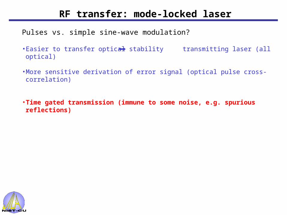
RF transfer: mode-locked laser
Pulses vs. simple sine-wave modulation?
• Easier to transfer optical stability transmitting laser (all optical)

RF transfer: mode-locked laser
Pulses vs. simple sine-wave modulation?
• Easier to transfer optical stability transmitting laser (all optical)
• More sensitive derivation of error signal (optical pulse cross-correlation)
RF transfer: mode-locked laser
Pulses vs. simple sine-wave modulation?
• Easier to transfer optical stability transmitting laser (all optical)
• More sensitive derivation of error signal (optical pulse cross-correlation)
• Time gated transmission (immune to some noise, e.g. spurious reflections)

RF transfer: mode-locked laser
Pulses vs. simple sine-wave modulation?
• Easier to transfer optical stability transmitting laser (all optical)
• More sensitive derivation of error signal (optical pulse cross-correlation)
• Time gated transmission (immune to some noise, e.g. spurious reflections)
• Simultaneously transmit optical and microwave
1/Optical standard RF standard

RF transfer: mode-locked laser
Pulses vs. simple sine-wave modulation?
• Easier to transfer optical stability transmitting laser (all optical)
• More sensitive derivation of error signal (optical pulse cross-correlation)
• Time gated transmission (immune to some noise, e.g. spurious reflections)
• Simultaneously transmit optical and microwave
Mode locked fiber laser
3.5 km
Frequency / time domain analysis
8th harmonic
8th harmonicLocal
Frequency reference
End user

Pulses minimize instability of photodetection:• Average power ; SNR
Transfer with mode-locked pulses
Holman et al. Opt. Lett. 29, 1554 (2004)
10-16
10-15
10-14
10-13
All
an D
evia
tio
n
1 10 100 1000
Averaging Time (s)
Modulated CW over 7 kmMode-locked pulses, noise floor
• Dispersion broadens pulse (~ 1 ns) more power to maintain SNR
but …
Noise floor ( )85 dB30 W
12.0 ( )80 dB660 W
Spectral Width (nm)
SNRPower
ML pulses =12.0 nm
• Recompress pulse
so …• Reduce bandwidth Noise floor ( )85 dB30 W
5.5 ()80 dB160 W
12.0 ( )80 dB660 W
Spectral Width (nm)
SNRPower
ML pulses =5.5 nm

Use dispersion shifted fiber in link
Photodiode Power
SNR Instability (1s)
40 W 85 dB 6e-14 ( )
40 W 85 dB 6e-15 ( )
Conditions at Receiver10
-15
10-14
10-13
All
an D
evia
tio
n
1 10 100 1000
Averaging Time (s)
Modulated CW over 7 km Mode-locked pulses, noise floor =5 nm, 4 km of DSF
Active stabilization of fiber length
• Active stabilization: free-space delay arm in-line with DSF• Not limited by receiver noise• Reduce Allan deviation to noise floor
81
2
4
6
810
2
4
6
8100
2
Integ
rated Jitter (fs)
101
102
103
104
105
106
107
Fourier Frequency (Hz)
2
4
6
80.1
2
4
6
81
2
4
6
Jitt
er S
pec
tral
Den
sity
(fs
/ H
z1/2
)
4 km of DSF, unstabilized 4 km of DSF, active stabilization Noise floor
Integrated jitter

Techniques and technology of:•Synchronization of ultrafast lasers •Delivering frequency standards over fiber networks
Can be applied to synchronization efforts at next generation light sources Shorter time scales with < 10 fs jitter at multiple locations will require:
•Optical delivery of clock signal•Active stabilization of optical fiber network •Some combination of RF and all-optical error signal generation (depends on frequency range of interest)
Main message:No showstoppers on synchronization
(financial or technical)
Summary / Future Work…


Compensate dispersion of installed fiber
3.5 km
81st harmonic
Local
End userMode locked fiber laser
Frequency reference
3.5 km
Dispersion compensation fiber
•Dispersion compensationAvg. power ; SNR
6
80.1
2
4
6
81
2
4
6
810
2
Jitt
er S
pec
tral
Den
sity
(fs
/ H
z1/2
)
100
101
102
103
104
105
106
107
Fourier Frequency (Hz)
1
10
100
1000
Integ
rated Jitter (fs)
7 km of installed fiber, unstabilized 7 km of installed fiber, active stabilization Noise floor
Integrated jitter
•Eliminate low frequency noise on installed fiber network

0 5 10 15 20 25 30 350
20
40
60
80
100
Cou
nts
Distance [µm]
5 µm
• Human Epithelial cell
• Image size is 50 by 50 microns
•Total acquisition time: 8 seconds
• Raman shift = 2845 cm-1
Pump 0.6 mW @ 250 kHzStokes 0.2 mW @ 250 kHz
Image taken by Dr. Eric Potma and Prof. Sunney Xie at Harvard University with synchronization system commercialized by Coherent Laser Inc.
Slice
Cell Image

Distribution over Fiber Networks
Optical Fiber Network
Degradation of signal during detection minimized
End User
End User
Noise added by fiber must be detected and minimized
Master Clock

Phase Coherent Transmission of Optical Standard
Nd:YAG
3.45 km fiber
AOM 1
Detection of Roundtrip Signal
correctedstandard at NIST
JILA I2 Atomic Clock
AOM 2
-1 order
+1 order
• Adjustment of AOM 1, shifts center frequency of Nd:YAG to compensate fiber perturbations
• AOM 2 differentiates local and roundtrip signals
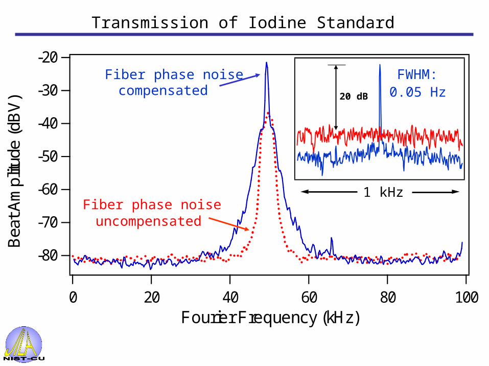
Transmission of Iodine Standard
Fiber phase noise uncompensated
Fiber phase noise compensated
FWHM:0.05 Hz
1 kHz
20 dB
-80
-70
-60
-50
-40
-30
-20
Bea
t Am
plitu
de (
dBV
)
100806040200Fourier Frequency (kHz)
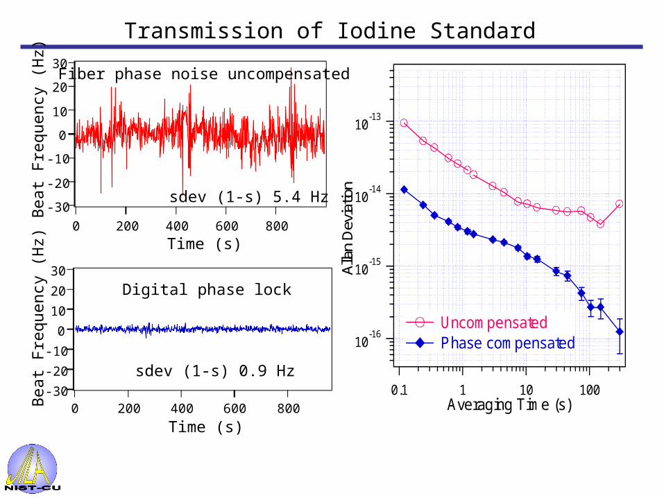
10-16
10-15
10-14
10-13
Alla
n D
evia
tion
0.1 1 10 100Averaging Time (s)
Uncompensated Phase compensated
-30
-20
-10
0
10
20
30
Be
at F
requ
ency
(H
z)
8006004002000
Time (s)
Fiber phase noise uncompensated
sdev (1-s) 5.4 Hz
-30
-20
-10
0
10
20
30
Be
at F
requ
ency
(H
z)
8006004002000
Time (s)
Digital phase lock
sdev (1-s) 0.9 Hz
Transmission of Iodine Standard

Techniques and technology of:•Synchronization of ultrafast lasers •Delivering frequency standards over fiber networks
can be (easily) applied to synchronization efforts at next generation light sources Shorter time scales with <10 fs jitter at multiple locations will require:
•Optical delivery of clock signal•Some combination of RF and all-optical error signal generation (depends on frequency range of interest)
Summary/Future Work…
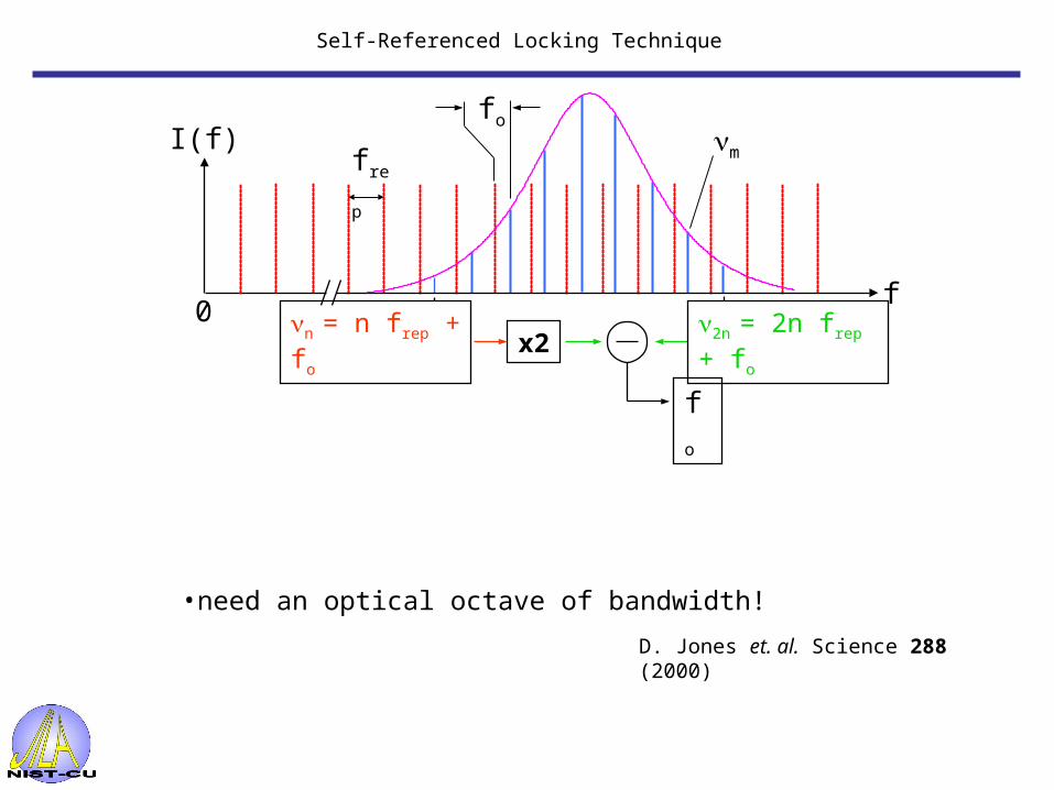
Self-Referenced Locking Technique
•need an optical octave of bandwidth!
I(f)
f0
n = n frep + fo
frep
x2 2n = 2n frep + fo
fo
fo
m
D. Jones et. al. Science 288 (2000)
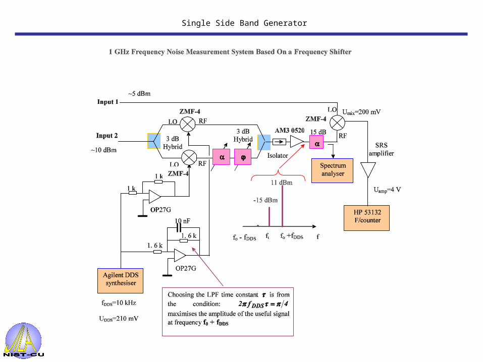
Single Side Band Generator

Outline
• Why transfer highly stable frequency standards?
• Current method for transfer of RF standard
• Mode-locked laser for RF transfer
• Active stabilization of transfer network

Instability of optical amplifier (EDFA)
Mode locked fiber laser
3.5 km
8th harmonicJitter spectral analysis (FFT)
LocalFrequency reference
End user
EDFA
2
4
6
1
2
4
6
10
2
4
6
Jitt
er S
pec
tral
Den
sity
(fs
/ H
z 1
/2)
100
101
102
103
104
105
106
107
Fourier Frequency (Hz)
10
100
1000
Integ
rated Jitter (fs)
7 km of installed fiber, without EDFA 7 km of installed fiber, with EDFA Noise floor, without EDFA
Integrated jitter
Conclusions
• 10x improvement with mode-locked pulses for RF transfer
• Reducing temporal stretching of pulse optical power ; SNR
• Active stabilization implemented instability = measurement noise floor for frequency transfer
• EDFA jitter well within stabilization loop bandwidth