LASER MACHINE Operation Manual
33
LASER MACHINE Operation Manual Model: Katana Address: 21 Blue Sky Court, Sacramento CA 95828 Phone: (916) 383- 8166 Email: [email protected]
Transcript of LASER MACHINE Operation Manual

LASER MACHINE Operation Manual
Model: Katana
Address: 21 Blue Sky Court, Sacramento CA 95828 Phone: (916) 383- 8166
Email: [email protected]

rev. 1.0 P. 2
Read and understand operation manual before using this machine.
Failure to follow operating instructions could result in death or serious injury.

rev. 1.0 P. 3
Table of Contents CO₂ Laser Safety & Policies 4
Fire & Hazardous Materials 5
Accessories 6
First Time Laser Setup 8
Unpacking and Setting up the Machine 9
Installing Other Accessories 17
Connecting Laser Machine to Computer 20
Sending files to your Laser Machine 25
Control Panel Keypad 26
Focusing the Lens 28
Maintenance 30
Troubleshooting 32

rev. 1.0 P. 4
CO₂ Laser Safety & Policies
WARNING: The safety precautions below are mandatory guidelines that must be followed. LightObject will not be held responsible for damages or injuries resulting from improper use of the laser machine. DO NOT operate the laser machine until you have been properly trained.
DO NOT make contact with any exposed wires on the machine.
DO NOT use any unapproved or unsafe materials such as Polyvinyl Chloride (PVC) which emits noxious gases that can harm your central nervous system.
DO NOT operate the laser near flammable/explosive substances.
DO NOT engrave on shiny metal or mirror as the laser beam can be reflected and deviate that may result in blindness or burn.
NEVER look directly at the laser while in operation and avoid exposure to laser.
NEVER set anything on top of the laser and/or on the worktable when not in use.
NEVER leave the laser machine running while unattended. Monitor the machine when it is running at all times to be able to hear and observe abnormalities and potential hazards.
NEVER push or pull on the laser head housing or gantry while the laser is running.
NEVER dismantle the laser machine as there are laser and high voltage parts that could harm or result in injury.
NEVER open the upper cover of the laser machine while it is running.
ALWAYS wear proper goggles during machine operation.
ALWAYS unplug the machine before making any further adjustments.
ALWAYS keep hands away from machine while operating and stand clear from laser tube area.
In Case of an Emergency:
TURN OFF the POWER SWITCH of the machine OR Press the EMERGENCY STOP button

rev. 1.0 P. 5
Fire & Hazardous Materials
WARNING: Leaving the machine unattended while in use can result in a fire and substantial damage to the machine and the building it resides in. Any damage caused by fire that is not due to defects in workmanship or the machine itself will NOT be covered by the LightObject warranty. Hazardous Materials: Any materials considered hazardous are NOT recommended to etch, cut or engrave. These materials can produce toxic fumes or cause the machine to not function properly. Materials that should NOT be used on the machine: Polycarbonate PVC Compounds Vinyl Fumes produced by above materials can cause irritation to eyes, skin and the respiratory tract. This material should not be exposed to elevated temperatures. Laser Safe Materials: Acrylic, Wood, Leather, Plastics (ABS, POM, Polyimide, PP, Styrene), Fabric, MDF, Cardboard, Paper, Foam, Fiberglass, rubber, Steel

rev. 1.0 P. 6
Accessories
Air Exhaust Fan (optional)
Tool Box with hand tools
Air Exhaust Hose (8” dia.)
Exhaust Hose Clamps
Tubing for Water Chiller
Laser Tube
Water Chiller (sold separately)
Air Pump (optional)
Laser Tube Extension Case
Pressure reducer regulator
gas meter pressure gauge

rev. 1.0 P. 7
Air compressor regulator pressure
gauge moisture filter
Other accessories 1) Spare tubing 2) Chiller Signal cable (comes with Water Chiller) 3) Ethernet Network LAN cable 4) Sets of Keys 5) USB cable 6) Laser cutting head tips 7) Cotton tipped sticks (for cleaning lens with alcohol) 8) Universal DSP remote controller (some functions are only available for specific
controller model) 9) Other tools for adjustment NOTE: Software LightBurn is sold separately

rev. 1.0 P. 8
First Time Laser Setup The following components are required for operating the laser machine: Air Assist: to blow smoke away from the beam, preventing damage to the lens and preventing burning the material.
Water Chiller: to circulate cool water into the laser tube to prevent the tube from overheating. The laser tube needs to be at a cool temperature of 15°C - 25°C or else the laser tube may overheat and potentially crack.
Silicone Tubing for Water Chiller and Air Pump: 2 hoses to transfer water for cooling of the laser tube and 1 hose (oxygen OR air from air pump OR compressed air) to blow air around the laser head.
Air Exhaust Hose and Air Exhaust Fan: to provide ventilation removing fumes from laser machine.

rev. 1.0 P. 9
Unpacking and Setting Up the Machine 1) Uncrate the laser machine.
2) Open up the laser machine and retrieve all accessories that may be inside the machine when shipped.
3) Once all of the accessories have been removed, you are now ready to begin setting up the machine.
4) Depending on the size of your laser tube, you may need to remove the side panel and install the laser tube extension case.

rev. 1.0 P. 10
5) Place the laser tube on the laser tube mounts.
If the machine is sold with the tube, there could be markings on the tube for easy alignment.
6) Connect the water tubing to the laser tube.

rev. 1.0 P. 11
Note: For high power tube, water cooling(WC) will be applied on the back of the mirror cover. Therefore, the water will cool both the laser tube and mirrors when operation.
7) Be sure to connect the silicone tubing on both sides of the laser tube. Connect
water tubing between chiller and machine. The correct direction of water flow is from high voltage side (red wire) of the laser tube to the low voltage side.

rev. 1.0 P. 12
(Chiller’s back side for reference only) Note: The water temperature should always be between 59-77 degrees Fahrenheit when running the machine. (15-25 Degrees Celsius). Some default temperature setting of water chiller is 25 degree Celsius.
8) Chiller Signal cable needs to be connected between water chiller’s alarm outlet and laser cutter. If it is not connected to the machine, it won’t fire.
(Chiller’s back side for reference only, depends on model)

rev. 1.0 P. 13
9) Fill up the water chiller with distilled water and power up, observe the water flow direction. Switch the input/output if it is wrong.
10) Check air bubble trapped in the laser tube. Squeeze the water tubing or tilt the laser tube carefully to get rid of the big bubble. Small bubbles are acceptable.
IMPORTANT: the tube can overheat quickly if large bubbles are present when the laser is firing which can cause the tube to crack.
11) Secure the laser tube on the laser tube mounts.

rev. 1.0 P. 14
(for reference only; different models come with different type of clamp)
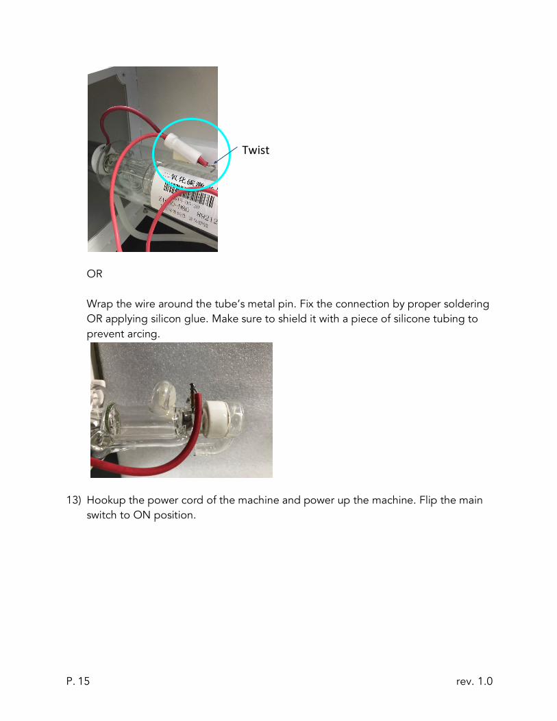
12) For screw type connection, clamp the wire under the screw. Put the rubber cap back on the tube on the high voltage side.
For wire type connection, make a twist like a hook and clamp the hook under the screw.
rev. 1.0 P. 15
OR Wrap the wire around the tube’s metal pin. Fix the connection by proper soldering OR applying silicon glue. Make sure to shield it with a piece of silicone tubing to prevent arcing.
13) Hookup the power cord of the machine and power up the machine. Flip the main switch to ON position.
Twist

rev. 1.0 P. 16
14) Release the emergency stop button.
15) Press the machine power button. The laser power button can be pressed later, when it is time to fire up the laser.
Power Machine

rev. 1.0 P. 17
Installing Other Accessories Exhaust Fan Installation Some materials such as leather or wood generate larger amounts of smoke than other materials. The exhaust is necessary to remove harmful fumes and smoke. The exhaust must be ducted to the outside and away from any area where animals or humans congregate. Connect the air exhaust hose by using the hose ring clamps provided, connecting the exhaust hose is done in the rear or underneath (varies based on machine). See picture below.
Turn the exhaust fan on when doing any cutting and engraving to remove the smoke and fumes.
Note: Avoid excessive length, kinks and turns when installing the exhaust pipe/hose.
Air Assist Connect the air pump to the laser machine air input. Turn on the air before doing any cutting or engraving to prevent any clouding on the lens and to prevent the material from burning CO2 metal cutter model come with high pressure tubing to enable easy upgrades for larger air compressor. An air pressure regulator is used along with an air compressor to adjust the air flow from your compressor to your laser machine. O2 should be used for cutting METAL. Air pressure should be adjusted to 80 - 90 PSI (0.55 MPa - 0.62 MPa) COMPRESSED AIR – for engraving / cutting NON-METAL 3 - 60 PSI (0.02- 0.42 MPa)

rev. 1.0 P. 18
AIR – for cutting NON-METAL
Air compressor regulator pressure
gauge moisture filter
Pressure reducer regulator gas meter
pressure gauge
Air Pump / Air Compressor The Air Pump or Air Compressor (sold separately) are used to blow air through the laser head. This will blow away debris and smoke from the laser beam while allowing for a cleaner cut and protecting the lens. The air compressor on/off switch should be close by and preferably on the same circuit as the water chiller and exhaust fan to ensure it is in operation while running the laser machine. The air valve switch is used to control the air flow of the air pump OR compressed air

rev. 1.0 P. 19
The pressure gauge is used to monitor the pressure of O2 (when cutting metal).

rev. 1.0 P. 20
Connecting Laser Machine to Computer The laser machine (with Ruida controller) can work with below software
a) MetalCut (for Windows only) b) RDWorks (for Windows only) c) LightBurn (for Mac and Windows)
Set up with MetalCut 1) Install the software MetalCut (Please check with LightObject if needed) 2) Connect the USB cable. 3) Under “Device”. It should show the device is connected with “USB:Auto”.
Note: If you have multiple windows opened (e.g. LightBurn windows), there could be issue on connection. Therefore, open one window at a time
4) Cutting metal
a) When your drawing is ready, please click on “Cut In/Out” to configure the “Cut in and out setting”. Then, check “Enable” and enter the Length and Angle. Then, click “Ok”.
b) Go to “User” tab in the menu on the right hand side. Set “Mixcut parameters” by setting “Enable pulse punch” to “Yes”
Cutting non-metal a) There is no need to enable “Cut In/Out". b) Go to “User” tab in the menu on the right hand side. Set “Mixcut
parameters” by setting “Enable pulse punch” to “No”.

rev. 1.0 P. 21
Set up with RDworks 1) Download and install the software RDWorks from http://www.rd-acs.com/ 2) Connect the USB cable. 3) Click on “Setting” in Device. It should show the device is connected.
Set up with LightBurn 1) Download and install the software LightBurn from https://lightburnsoftware.com/ 2) Connect the USB cable.

rev. 1.0 P. 22
3) Follow the instruction from the screen, and it will guide you connecting the computer to the laser machine.

rev. 1.0 P. 23

rev. 1.0 P. 24
NOTE: Please refer LightBurn instruction manual and tutorials in their site for configuration and usage
If you are using LAN connection, input the same IP address set on the laser controller. NOTE: Please make sure LAN cable is connected between computer and laser machine. 4) Press Menu on the controller panel 5) Select “System config” 6) Select “Read” 7) IP address should be shown e.g.169.254.164.041 (depends your network)Click
“Devices
8) Click “Create Manually” 9) Select “Ruida” in New Device Wizard”, click “Next” 10) Choose “Ethernet/UDP” 11) Input the IP address you have seen in the DSP control panel e.g.169.254.169.041 12) Input the Name you would like to call it 13) Input the dimensions of the work area e.g. 1300mm for the width, 2500mm for the
height 14) Select the origin, then click “Next” 15) It will show the setting, then click “Finish”

rev. 1.0 P. 25
Sending files to your Laser Machine Once you have established the connection between the computer and the laser machine, job files can be transferred. To do this, click on the Sent button(LightBurn) OR Download button(RDWorks and MetalCut) located on the right side of the laser software. Alternatively, save the file as UFile and put in a USB stick. Then download the file from the USB stick on the laser control panel.

rev. 1.0 P. 26
Control Panel Keypad
Note: Since the laser cutter can be connected to different controllers and system (e.g. Ruida RDC6332G and LFS-PM Series Live Focus System), please always refer to the controller manual and system manual for details. Functions of typical keypad: Reset: Refresh the system and will stop all running applications and return to the main interface. Start/Pause: Start or Pause the current work on the laser Stop: Stop all running applications Origin: Select the starting point of your file within the work table. Pulse: Pulses the laser beam Frame: Show you the framed area of which your file will run in File: Show the management of the memory Sending files to your Laser Machine and Udisk files Speed: Set the speed of the current running layer, or to set the direction keys’ move speed Max. Power: Set the maximum laser power of the current running layer or set the power of the “Pulse” key Min. Power: Set the minimum laser power of the current running layer Left & Right Arrow: Move the X-axis of the left/right cursor Up & Down Arrow: Move the Y-axis or the up/down cursor Z+ & Z-: Move the Z-axis Home: The Home key can be pressed when the system is idle, or the work is finished. Each Axis goes home Esc: Stop the current work that the machine is doing or to exit the current menu

rev. 1.0 P. 27
Enter: Validate the choice or change. Diagnose: Diagnose the system such as the limiter status, water protect etc.
Universal DSP remote controller (some functions are only available for specific controller model and machine) Below functions which are available for general machines. Pulse: Laser emission Frame: Moving with the maximum border of the cutting file X arrows: Manual movement of X axis
Y arrows: Manual movement of Y axis
Origin: Set the origin position
Cancel: Cancel the current operation
Start: Start cutting
Reset: Reset the motion controller
Stop: Stop the cutting and cancel the job

rev. 1.0 P. 28
Focusing the Lens (For non-metal cutting) Manual Focus: The lens should be adjusted and focused according to the thickness and type of material. To adjust the focus, adjust the height to accommodate the thickness of the material by pressing the up and down arrows in the auto focus panel
Make sure FOLLOW - > “OFF” for non-metal cutting

rev. 1.0 P. 29
Do some cuttings on the material, and try to find the smallest burnt on the material by adjusting the height of the tip. The smallest burnt you find with that specific height means it is focused. OR You may do a ramp test. Put a piece of wood at an angle like a ramp. Laser cut a line across it. Move the laser head over the narrowest section of burn mark. The gap between the tip and the material is the focus height. Laser tip: For cutting Non-metal: Always use non-metal tips For cutting metal: Always use metal tips (For metal cutting) Auto-Focus: 1) Enable FOLLOW - > “ON” or live auto focus system.
Note: Make sure the metal piece is CLEAN and not TOO SMALL. Otherwise, the laser head would not be able to detect the metal piece and the tip will crash on the metal piece.
2) Click “Function” 3) Click “Capacitance Calibration”

rev. 1.0 P. 30
4) Place the metal sheet you want to cut on the bed. Move cutting head above the metal.
5) Click “Start” for Calibration”. During the calibration process, please make sure the tip not hitting the metal sheet. If it does, press the Emergency button to Stop the operation. The machine will stop. You can just simply restart the machine by moving the laser head up and try to do the calibration again.
6) After the Calibration is completed, click “Enter” and “Back”. Now, it is autofocused.
7) You may change the air setting under touchscreen between air and oxygen(high pressure channel). By default, the lowest oxygen protection setting is 0.3MPa; the controller will give alarm for under pressure. You may adjust it using a flat head screw driver.

rev. 1.0 P. 31
Maintenance Cooling:
Automotive antifreeze should not be used as a laser coolant. Distilled water shall be used. The coolant should always be clean and clear.
Focal lens:
This is the lens that is used to focus the laser beam. This lens should be cleaned at least once per week. It is not possible to clean the lens while it is mounted in the focal tube. The laser beam alignment should be checked after cleaning is completed. If there is any incident of fire or large issue of smoke/fumes, then it is advised to check the lens and clean it. Use denatured alcohol and/or acetone as the cleaning solvent. Use a lens tissue or cotton tipped swabs.
The focal lens should be replaced if it is cracked, the coating is scratched/pitted, the core material is darkened, the coating is delaminating, or any other significant damage is found.
To remove the lens, jog down the laser head to have enough space. Rotate out the right-hand thread barrel as shown in the picture. The female thread above the red arrow is for securing long focal length lens.

rev. 1.0 P. 32
In case, if the lens’ position needs to be adjusted, user can change the distance between the nozzle and the lens, loosen the set screw, then turn the up/down adjustment. For thin metal, usually focal point is at 1mm outside of the nozzle. The lower four screws are for adjusting nozzle position.
If the job does not run showing protection alarm is on, it maybe you’ve touched the laser nozzle. Reset the autofocus in this case. Mirror: This mirror should be cleaned at least every three months.
Laser Alignment:
WARNING: DO NOT obstruct the path of the laser, beam is invisible!
NOTE: Due to transportation, the alignment may be off.
1) To make sure that the laser is properly aligned, place an adhesive note around the alignment housing next to the mirror.
2) Set the laser power low to avoid burning the paper. 3) Start with the first mirror; press the laser button once. If that mirror is aligned
correctly, the burned mark should be in the center of the circle on the housing. If it is not aligned, then the three screws for each mirror must be adjusted little by little until the laser hits the center. Test after each adjustment.
4) Once the first mirror is done, repeat the steps to align the 2nd mirror. 5) When mirrors are aligned correctly, the mark will be in the center regardless of the x
and y position (wherever the laser head moves).
up/down adjust Set Screw

rev. 1.0 P. 33
Troubleshooting The machine does not turn on:
Make sure to check below
1. Does the power supply function properly? 2. Is the emergency button pressed? 3. Is the power switch turned to the on position?
Laser does not fire:
Make sure to check below
1. Check if the water chiller functions properly 2. All doors are closed
Autofocus reading is incorrect: Check all wiring connection on laser head are not loose.
Clean the nozzle tip.
The ceramic part above the nozzle may need replacement.