Laser Beam Shaping by Interference: Desirable...
16
9 Laser Beam Shaping by Interference: Desirable Pattern Liubov Kreminska University of Nebraska-Kearney, Department of Physics and Physical Science USA 1. Introduction Laser beam shaping is an active discipline in optics owing to its importance to both illumination and detection processes. The formation of single or multiple optical vortices in a laser beam has taken on recent interest in areas ranging from electron and atom optics to astronomy. Here we describe our efforts to create localized vortex cores using only the interference of several laser beams with Gaussian profile, a method that may be particularly suited to the application of vortex modes to intense femtosecond laser pulses. For many years the study of optical vortex formation has been of interest as a problem in itself and one typical of many linear and nonlinear optical phenomena (Nye et al., 1988) such as the formation of speckles, the appearance of solitons, operation of laser and photorefractive oscillators in transverse modes, the self-action of the laser oscillation in nonlinear media (Swartzlander, Jr. & Law, 1992; Kreminskaya et al., 1995); creation of optical vortices in femtosecond pulses (I. Mariyenko et al., 2005); investigation of atomic vortex beams in focal regions (Helseth, 2004), etc. The investigation and explanation of the pattern formation by different optical systems was activated for recent years (Karman et al., 1997; Brambilla et al.,1991); efficient generation of optical vortices by a kinoform-type spiral phase plate (Moh et al., 2006; Kim et al., 1997). These two apparently different problems of pattern formation and vortex formation are the manifestation of the same phenomenon, which we explain by interference of many plane waves (Angelski et al., 1997; Kreminskaya et al., 1999; Masajada & Dubik, 2001). An optical vortex (or screw dislocation, phase defect or singularity) is defined as the locus of zero intensity accompanied by a jump of phase on ±2πm radians, occurring during a round- trip (Nye & Berry, 1974; Basistiy et al., 1995; Abramochkin & Volostnikov; 1993). The integer m is the topological charge, the sign corresponds to the direction of the phase growth: “+” to counterclockwise and “-“to clockwise. In the transversal cross-section, the optical vortex reveals itself as a point, in the 3-D space it exists along the line. A doughnut mode of laser beam is the example of optical vortex. Other member of optical dislocations family is the edge dislocation. The phase changes here by π radians. The shape of the edge dislocation is a line in the transversal cross-section and a plane in 3-D space. Interference pattern of the Young’s experiment is the example of the edge dislocation. For the complex amplitude of the light, the condition of the zero intensity means simultaneous zero of the real and imaginary parts of the complex amplitude. www.intechopen.com
Transcript of Laser Beam Shaping by Interference: Desirable...
9
Laser Beam Shaping by Interference: Desirable Pattern
Liubov Kreminska University of Nebraska-Kearney,
Department of Physics and Physical Science USA
1. Introduction
Laser beam shaping is an active discipline in optics owing to its importance to both illumination and detection processes. The formation of single or multiple optical vortices in a laser beam has taken on recent interest in areas ranging from electron and atom optics to astronomy. Here we describe our efforts to create localized vortex cores using only the interference of several laser beams with Gaussian profile, a method that may be particularly suited to the application of vortex modes to intense femtosecond laser pulses. For many years the study of optical vortex formation has been of interest as a problem in itself and one typical of many linear and nonlinear optical phenomena (Nye et al., 1988) such as the formation of speckles, the appearance of solitons, operation of laser and photorefractive oscillators in transverse modes, the self-action of the laser oscillation in nonlinear media (Swartzlander, Jr. & Law, 1992; Kreminskaya et al., 1995); creation of optical vortices in femtosecond pulses (I. Mariyenko et al., 2005); investigation of atomic vortex beams in focal regions (Helseth, 2004), etc. The investigation and explanation of the pattern formation by different optical systems was activated for recent years (Karman et al., 1997; Brambilla et al.,1991); efficient generation of optical vortices by a kinoform-type spiral phase plate (Moh et al., 2006; Kim et al., 1997). These two apparently different problems of pattern formation and vortex formation are the manifestation of the same phenomenon, which we explain by interference of many plane waves (Angelski et al., 1997; Kreminskaya et al., 1999; Masajada & Dubik, 2001). An optical vortex (or screw dislocation, phase defect or singularity) is defined as the locus of zero intensity accompanied by a jump of phase on ±2πm radians, occurring during a round-trip (Nye & Berry, 1974; Basistiy et al., 1995; Abramochkin & Volostnikov; 1993). The integer m is the topological charge, the sign corresponds to the direction of the phase growth: “+” to counterclockwise and “-“to clockwise. In the transversal cross-section, the optical vortex reveals itself as a point, in the 3-D space it exists along the line. A doughnut mode of laser beam is the example of optical vortex. Other member of optical dislocations family is the edge dislocation. The phase changes here by π radians. The shape of the edge dislocation is a line in the transversal cross-section and a plane in 3-D space. Interference pattern of the Young’s experiment is the example of the edge dislocation. For the complex amplitude of the light, the condition of the zero intensity means simultaneous zero of the real and imaginary parts of the complex amplitude.
www.intechopen.com
Laser Systems for Applications
172
The experimental detection of vortices is accomplished by interference with a reference beam that results in m new fringes appearing in the off-axis interference scheme, etc. In our experiment, the detection of the phase was performed by the Electronic Speckle Pattern Interferometry (ESPI) system (Khizhnyak & Markov, 2007; Malacara, 2005). In this paper the process of optical vortex arising from the interference of plane waves was studied both theoretically and experimentally as a continuation of the fundamental prediction of (Rozanov, 1993). On the base of this study the simple and convenient method of the vortex creation is proposed. An explanation of an appearance of phase singularities and hexagonal pattern in an initially smooth laser beam is given.
2. Theoretical approach and numerical modelling
The plane wave is the solution of the wave equation and could be described in Cartesian coordinates as (Born&Wolf, 1980):
0 exp( )U A i (1)
0 0sin cos sin sin cos kr kx ky kz , (1.1)
where U is the complex field amplitude, A0 is the amplitude, is the phase, k is the wave
vector, r is the radius- vector, 0 is the initial phase shift, ψ and are polar and
azimuthal angles in the spherical system of coordinates. Wavefronts of the plane wave are equally spaced parallel planes perpendicular to the wave vector and have zero topological indices. For our problem of search of singularities, the condition of zero intensity is equivalent to simultaneous zero of real and imaginary part of the complex field amplitude. All calculations were performed using Wolfram Mathematica 6.
2.1 The interference of two plane waves Let two plane waves interfere. The well-known periodical pattern of white and black fringes appears in any cross-section of the intensity distribution, Fig.1,a:
2 2 2 2
12 1 2 1 2 1 2 1 22 cos( ) U U U A A A A , (2)
The period of the pattern depends on the angle between interfering waves and is equal to
/(2sin( /2)) (2.1)
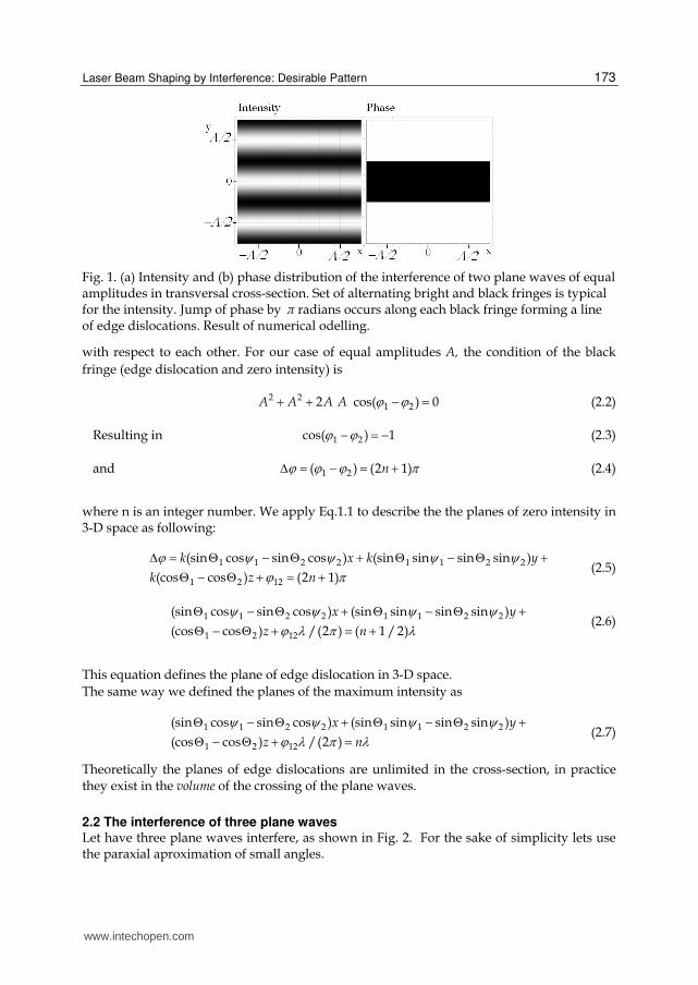
where λ is the wavelength. The phase undergoes shifts by in crossing every black fringe, producing edge dislocation, Fig.1,b. If the amplitudes of waves are equal (A, for example), the range of intensity (Eq.2) goes from maximum value of 4A2 to exact zero. The contrast of this pattern equals to one. Further, according to the principle of independent propagation, two interfering waves move forward and interfere again and again, producing patterns with the same period in subsequent cross-sections. Sets of planes of equal amplitude and/or phase are shifted on π
www.intechopen.com
Laser Beam Shaping by Interference: Desirable Pattern
173
Fig. 1. (a) Intensity and (b) phase distribution of the interference of two plane waves of equal amplitudes in transversal cross-section. Set of alternating bright and black fringes is typical for the intensity. Jump of phase by π radians occurs along each black fringe forming a line of edge dislocations. Result of numerical odelling.
with respect to each other. For our case of equal amplitudes A, the condition of the black fringe (edge dislocation and zero intensity) is
2 21 22 cos( ) 0 A A A A (2.2)
Resulting in 1 2cos( ) 1 (2.3)
and 1 2( ) (2 1) n (2.4)
where n is an integer number. We apply Eq.1.1 to describe the the planes of zero intensity in 3-D space as following:
1 1 2 2 1 1 2 2
1 2 12
(sin cos sin cos ) (sin sin sin sin )
(cos cos ) (2 1)
k x k y
k z n
(2.5)
1 1 2 2 1 1 2 2
1 2 12
(sin cos sin cos ) (sin sin sin sin )
(cos cos ) /(2 ) ( 1 / 2)
x y
z n
(2.6)
This equation defines the plane of edge dislocation in 3-D space. The same way we defined the planes of the maximum intensity as
1 1 2 2 1 1 2 2
1 2 12
(sin cos sin cos ) (sin sin sin sin )
(cos cos ) /(2 )
x y
z n
(2.7)
Theoretically the planes of edge dislocations are unlimited in the cross-section, in practice they exist in the volume of the crossing of the plane waves.
2.2 The interference of three plane waves Let have three plane waves interfere, as shown in Fig. 2. For the sake of simplicity lets use the paraxial aproximation of small angles.
www.intechopen.com
Laser Systems for Applications
174
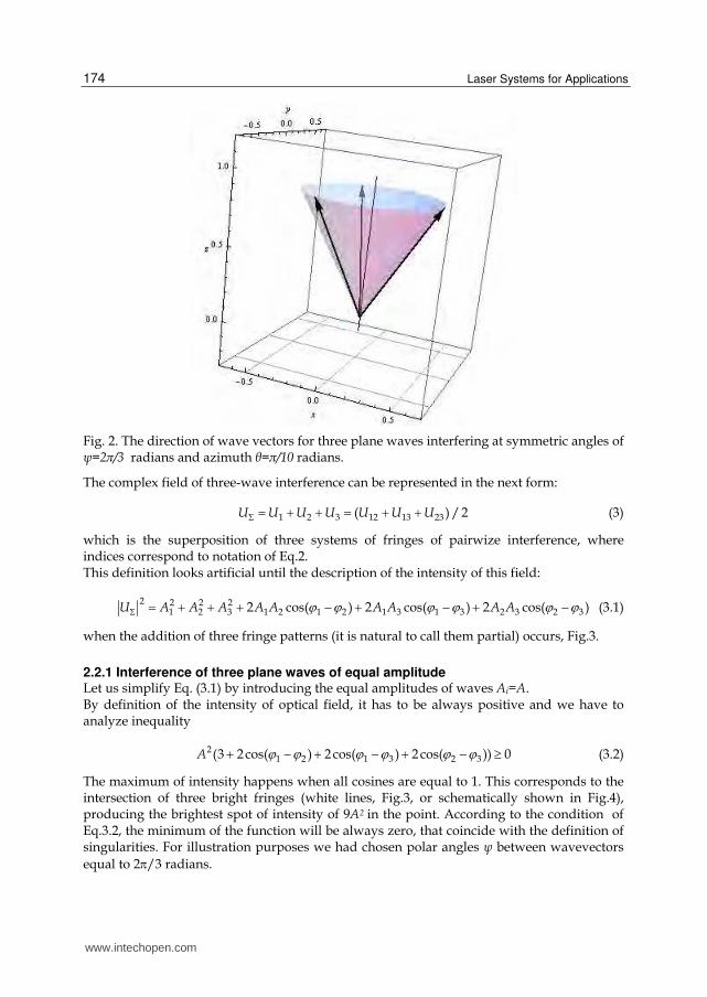
Fig. 2. The direction of wave vectors for three plane waves interfering at symmetric angles of ψ=2π/3 radians and azimuth θ=π/10 radians.
The complex field of three-wave interference can be represented in the next form:
1 2 3 12 13 23( ) / 2 U U U U U U U (3)
which is the superposition of three systems of fringes of pairwize interference, where indices correspond to notation of Eq.2. This definition looks artificial until the description of the intensity of this field:
2 2 2 21 2 3 1 2 1 2 1 3 1 3 2 3 2 32 cos( ) 2 cos( ) 2 cos( )U A A A A A A A A A (3.1)
when the addition of three fringe patterns (it is natural to call them partial) occurs, Fig.3.
2.2.1 Interference of three plane waves of equal amplitude Let us simplify Eq. (3.1) by introducing the equal amplitudes of waves Ai=A. By definition of the intensity of optical field, it has to be always positive and we have to analyze inequality
21 2 1 3 2 3(3 2 cos( ) 2 cos( ) 2 cos( )) 0 A (3.2)
The maximum of intensity happens when all cosines are equal to 1. This corresponds to the intersection of three bright fringes (white lines, Fig.3, or schematically shown in Fig.4), producing the brightest spot of intensity of 9A2 in the point. According to the condition of Eq.3.2, the minimum of the function will be always zero, that coincide with the definition of singularities. For illustration purposes we had chosen polar angles ψ between wavevectors equal to 2/3 radians.
www.intechopen.com
Laser Beam Shaping by Interference: Desirable Pattern
175
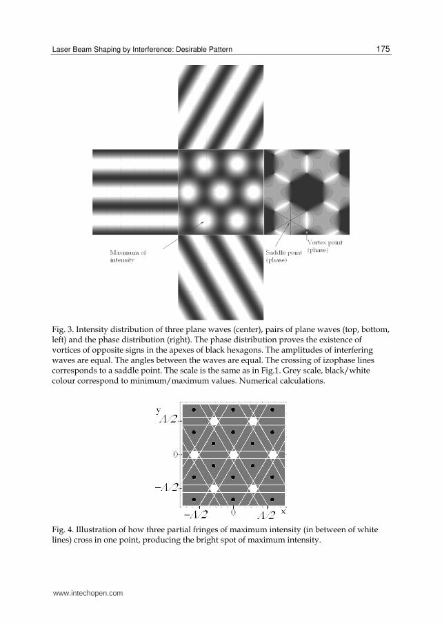
Fig. 3. Intensity distribution of three plane waves (center), pairs of plane waves (top, bottom, left) and the phase distribution (right). The phase distribution proves the existence of vortices of opposite signs in the apexes of black hexagons. The amplitudes of interfering waves are equal. The angles between the waves are equal. The crossing of izophase lines corresponds to a saddle point. The scale is the same as in Fig.1. Grey scale, black/white colour correspond to minimum/maximum values. Numerical calculations.
Fig. 4. Illustration of how three partial fringes of maximum intensity (in between of white lines) cross in one point, producing the bright spot of maximum intensity.
www.intechopen.com
Laser Systems for Applications
176
The important restrictions on the type of resulting pattern follows from the Eq.3.2, specifically, the partial black fringes never cross in a point (cosines can not be equal to -1 simultaneously, because the intensity could not be equal to a negative number -3).
2.2.2 Interference of three plane waves at different angles We keep investigating interference of three plane waves of equal amplitude. Let’s tilt one wave by 0.5 radians. The resulting pattern is shown in Fig.5.
(a) (b)
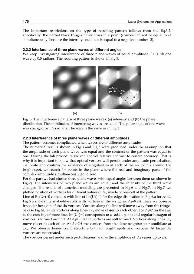
Fig. 5. The interference pattern of three plane waves: (a) intensity and (b) the phase distribution. The amplitudes of interfering waves are equal. The polar angle of one wave was changed by 0.5 radians. The scale is the same as in Fig.1.
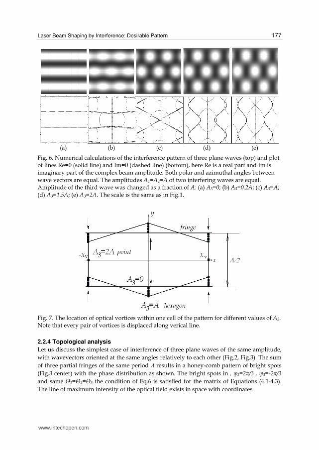
2.2.3 Interference of three plane waves of different amplitudes The pattern becomes complicated when waves are of different amplitudes. The numerical results shown in Fig.3 and Fig.5 were produced under the assumption that the amplitude of each plane wave was equal and the contrast of the pattern was equal to one. During the lab procedure we can control relative contrast to certain accuracy. That is why it is important to know that optical vortices will persist under amplitude perturbation. To locate and confirm the existence of singularities at each of the six points around the bright spot, we search for points in the plane where the real and imaginary parts of the complex amplitude simultaneously go to zero. For this part we had chosen three plane waves with equal angles between them (as shown in Fig.2). The intensities of two plane waves are equal, and the intensity of the third wave changes. The results of numerical modeling are presented in Fig.6 and Fig.7. In Fig.7 we plotted position of vortices for different values of A3, inside of one cell of the pattern. Line of Re(UΣ)=0 coincides with line of Im(UΣ)=0 for the edge dislocation in Fig.6,a for A3=0. Fig.6,b shows the snake-like rolls with vortices in the wriggles, A3=0.2A. Here we observe irregular hexagon of the six vortices. Vortices along the line x=0 move away from the fringes of case Fig.6a, while vortices along lines ±xv move closer to each other. For A3=A in the Fig. 6c the crossing of three lines Im(UΣ)=0 corresponds to a saddle point and regular hexagon of vortices is formed around. At A3=1.5A the vortices are still formed. Vortices along lines ±xv move closer to each other. At A3=2A the vortices from the close neighbor pair annihilate at ±xv. We observe honey comb structure both for bright spots and vortices. At larger A3 vortices are not created. The vortices persist under such perturbations, and as the amplitude of A3 varies up to 2A.
www.intechopen.com
Laser Beam Shaping by Interference: Desirable Pattern
177
(a) (b) (c) (d) (e)
Fig. 6. Numerical calculations of the interference pattern of three plane waves (top) and plot of lines Re=0 (solid line) and Im=0 (dashed line) (bottom), here Re is a real part and Im is imaginary part of the complex beam amplitude. Both polar and azimuthal angles between wave vectors are equal. The amplitudes A1=A2=A of two interfering waves are equal. Amplitude of the third wave was changed as a fraction of A: (a) A3=0; (b) A3=0.2A; (c) A3=A; (d) A3=1.5A; (e) A3=2A. The scale is the same as in Fig.1.
Fig. 7. The location of optical vortices within one cell of the pattern for different values of A3. Note that every pair of vortices is displaced along verical line.
2.2.4 Topological analysis
Let us discuss the simplest case of interference of three plane waves of the same amplitude, with wavevectors oriented at the same angles relatively to each other (Fig.2, Fig.3). The sum of three partial fringes of the same period results in a honey-comb pattern of bright spots (Fig.3 center) with the phase distribution as shown. The bright spots in , ψ2=2π/3 , ψ3=-2π/3 and same Θ1=Θ2=Θ3 the condition of Eq.6 is satisfied for the matrix of Equations (4.1-4.3). The line of maximum intensity of the optical field exists in space with coordinates
www.intechopen.com
Laser Systems for Applications
178
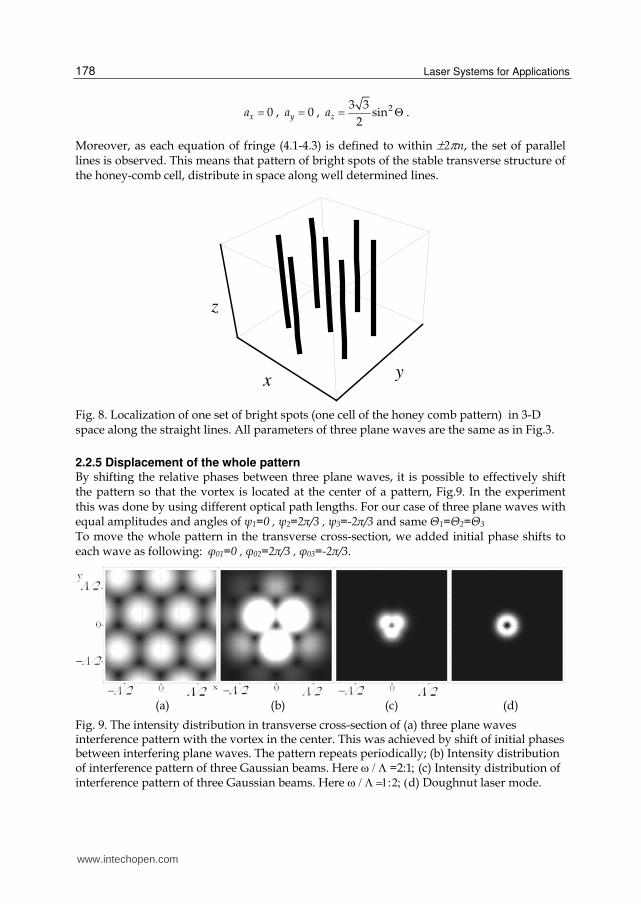
0xa , 0ya , 23 3sin
2 za .
Moreover, as each equation of fringe (4.1-4.3) is defined to within 2n, the set of parallel lines is observed. This means that pattern of bright spots of the stable transverse structure of the honey-comb cell, distribute in space along well determined lines.
xy
z
Fig. 8. Localization of one set of bright spots (one cell of the honey comb pattern) in 3-D space along the straight lines. All parameters of three plane waves are the same as in Fig.3.
2.2.5 Displacement of the whole pattern By shifting the relative phases between three plane waves, it is possible to effectively shift the pattern so that the vortex is located at the center of a pattern, Fig.9. In the experiment this was done by using different optical path lengths. For our case of three plane waves with equal amplitudes and angles of ψ1=0 , ψ2=2π/3 , ψ3=-2π/3 and same Θ1=Θ2=Θ3 To move the whole pattern in the transverse cross-section, we added initial phase shifts to each wave as following: φ01=0 , φ02=2π/3 , φ03=-2π/3.
(a) (b) (c) (d)
Fig. 9. The intensity distribution in transverse cross-section of (a) three plane waves interference pattern with the vortex in the center. This was achieved by shift of initial phases between interfering plane waves. The pattern repeats periodically; (b) Intensity distribution of interference pattern of three Gaussian beams. Here=2:1(c) Intensity distribution of interference pattern of three Gaussian beams. Hered) Doughnut laser mode.
www.intechopen.com
Laser Beam Shaping by Interference: Desirable Pattern
179
When compare the Fig 9a to the intensity distribution in Fig.3 center, one can see, that the vortex is located in point (0,0), as opposed to the bright spot with maximum intensity in the same point (0,0). The period of the pattern did not change.
2.2.6 Interference of three Gaussian beams The real laser beam has a finite aperture, its amplitude depends on coordinates as
U=A0exp-(x^2+y^2)/ω^2 (4)
with being the waist of the laser Gaussian beam. That is why we should not predict the periodic pattern to continue throughout all of space as a tessellation, both in transverse and longitudinal directions. Instead, the interference is confined locally. Mathematically, we achieve this finite spatial extent by modulating the amplitude of interfering plane waves with a Gaussian profile of Eq.4; this gives us a local area with interference pattern. This approach works well in the paraxial approximation. In the experiment, the small angles between interfering laser beams justify the use of this approximation. In Figs. 9.b,c we see that the pattern does not persist throughout the xy-plane, but is restricted to a small region of the transverse cross section. In this case the waist of the laser Gaussian beam was equal to the 2*spatial period of the two-beam interference pattern). At this point, there exists a competitive interaction between two parameters: the period of the hexagonal pattern of vortices, which is controlled by the angle of interference, and the off axis attenuation, which is controlled by the waist of the laser beam. By increasing the attenuation, we can further decrease any off center intensity contributions and retain only the center black spot and its immediately surrounding bright ring, Fig.9,c. One would like to have this type of intensity profile to be as close as possible to the doughnut mode. Doughnut modes correspond to a first order Laguerre-Gaussian laser mode with a profile depicted in Fig.9d. This result is important for application like doughnut mode creation for the temporally focusing of electron pulses (Hilbert et al.,2009), (Helseth, 2004).
2.3 Interference of many plane waves We performed modelling of interference of larger number of plane waves to explore the possibility of creation of different patterns and vortex tesselations. Various patterns can be created in the space, Fig.10. Between patterns of three-wave, five-wave and seven-wave interference the common features are as following: the bright central spot is formed, there is a radial symmetry, the number of vortices around the center is 2n, where n is the number of interfering waves, in the phase distribution one can see the saddle point of the order (n-1). The black circles of edge dislocations and bright circles surround the central bright spot.
3. Experimental setup
The four-arm Mach-Zhender interferometer was assembled for our experimental investigation, Fig.11. Three arms were used to form the field under study and the fourth was used as the reference one. A He-Ne laser with Rayleigh range zR=πw2/λ=1.5 m was used as the light source. The reflectivity of the cube beamsplitters (BS) was 50/50 to obtain a set of interference patterns with equal high contrast. Optical attenuators were used to reach this condition precisely. All optical surfaces were covered with antireflection coatings to reduce reflection losses.
www.intechopen.com
Laser Systems for Applications
180
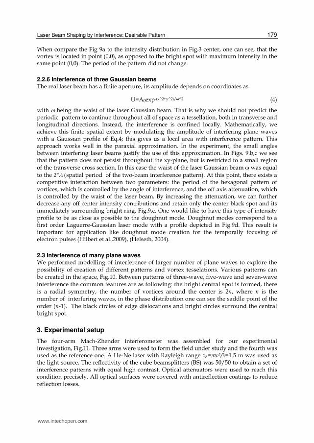
Fig. 10. Numerical calculations of the interference pattern of five plane waves (top) and of seven plane waves (bottom). Intensity distribution is shown in the first column, the phase distribution is shown in the second column and the plot of lines Re=0 (solid line) and Im=0 (dashed line) (third column). Angles between wave vectors are equal. The amplitudes of interfering waves are equal. The scale is related to the period of the two-waves interference as shown on the side.
The ESPI-system (Khizhnyak &Markov, 2007) was used for the phase reconstruction. To perform the phase reconstruction one of the totally reflective mirrors of the interferometer was placed to piezomotor, which allowed to move the mirror by fraction of the wavelength. We recorded pattern of interference of three beams under study and one reference beam (oriented at relatively large angle to obtain the frequent thin fringes to identify vortices as bifurcation of the fringe). Several snapshots were recorded by CD camera, stored in the memory of the computer and processed. As a result, we had a graph of the phase in the transversal cross-section. With three-beam interference, different fields are formed depending on parameters of interfering waves, for example, the field of honey-comb structure of bright spots (Fig.12,a), for which optical vortices exist at the vertices of hexagons (Fig.3,b). The frame of the reconstructed phase of the field proves the existence of vortices as its disruption on 2 radians inside one hexagonal cell. The neighbouring vortices are of opposite topological charge, i.e. the phase increases in opposite directions. It was found experimentally that the location of vortex is the straight line along the axis of light propagation that supports theoretical predictions of the Chapter 2. In the transverse cross-section the pattern of vortices is the regular hexagonal for equal angles of plane waves, otherwise hexagons are irregular: the greater these angles the smaller the sizes of the hexagons.
www.intechopen.com
Laser Beam Shaping by Interference: Desirable Pattern
181
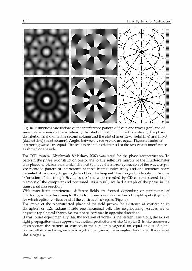
Fig. 11. A 633 nm linearly polarized HeNe laser at 5 mW sends a beam off one mirror. The beam entering a Mach-Zehnder configuration. The interferometer is a modified Mach-Zehnder which combines a total of four beams. In the fourth Mach-Zehnder arm the laser beam is redirected by a mirror, the position of which can be changed by a piezomotor stage. After recombination of the required number of beams the interference pattern is projected on a screen. A camera was used to capture the image. To help make finer adjustments to the pattern, we put a 3mm glass window in one of the beam paths. This allowed us to make minute changes to the path length of that beam by adjusting the angle of the window.
(a) (b)
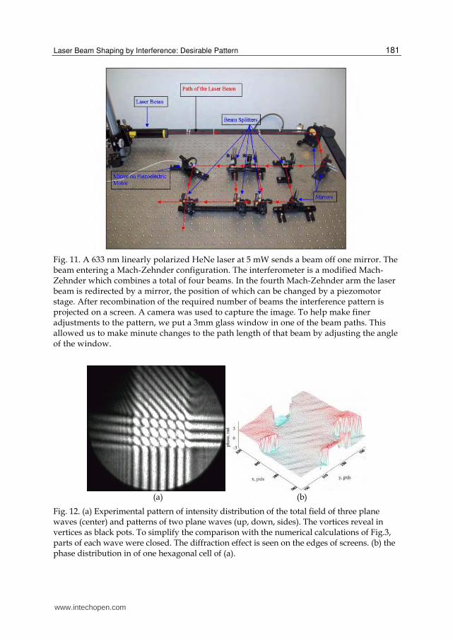
Fig. 12. (a) Experimental pattern of intensity distribution of the total field of three plane waves (center) and patterns of two plane waves (up, down, sides). The vortices reveal in vertices as black pots. To simplify the comparison with the numerical calculations of Fig.3, parts of each wave were closed. The diffraction effect is seen on the edges of screens. (b) the phase distribution in of one hexagonal cell of (a).
www.intechopen.com
Laser Systems for Applications
182
(a) (b)
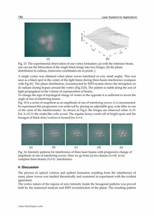
Fig. 13. The experimental observation of one vortex formation: (a) with the reference beam, one can see the bifurcation of the single black fringe into two fringes, (b) the phase distribution in radians, transverse coordinates are in pixels. ).
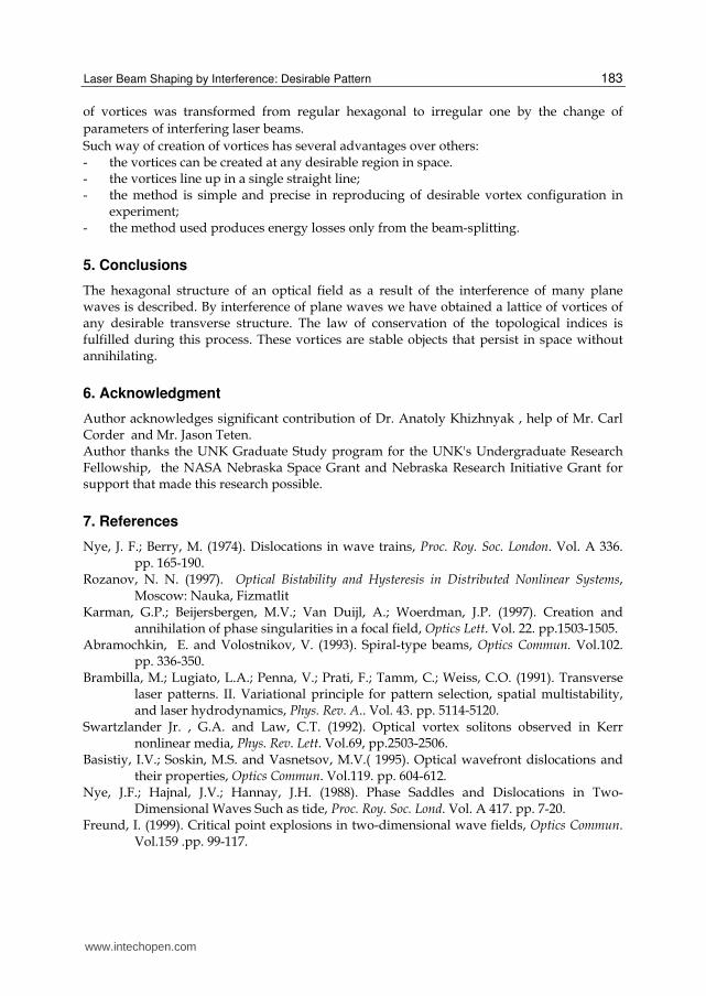
A single vortex was obtained when plane waves interfered at very small angles. This was seen as a black spot in the center of the light beam during three-beam interference (compare with Fig.9c). The phase distribution, reconstructed by ESPI-system shows the disruption on 2 radians during bypass around the vortex (Fig.13,b). The pattern is stable along the axis of light propagation in the volume of superposition of beams. To change the sign of topological charge of vortex to the opposite it is sufficient to invert the angle of one of interfering beams. Fig. 14 is a series of snapshots as an amplitude of one of interfering waves A3 is incremented. In experiment this progression was achieved by placing an adjustable gray scale filter in one of the arms of the interferometer. As shown in Fig.6, the fringes are observed when A3=0.
For A3=0.2A the snake-like rolls reveal. The regular honey-comb cell of bright spots and the hexagon of black dots/vortices is formed for A3=A.
(a) (b) (c) (d) (e)
Fig. 14. Intensity patterns for interference of three laser beams with progressive change of amplitude of one of interfering waves. Here we go from (a) two beams (A3=0) to (e) complete three beams (A3=A) interference.
4. Discussion
The process of optical vortices and pattern formation resulting from the interference of many plane waves was studied theoretically and examined in experiment with the evident agreement. The vortex nature of the regions of zero intensity inside the hexagonal patterns was proved both by the numerical analysis and ESPI reconstruction of the phase. The resulting pattern
www.intechopen.com
Laser Beam Shaping by Interference: Desirable Pattern
183
of vortices was transformed from regular hexagonal to irregular one by the change of parameters of interfering laser beams. Such way of creation of vortices has several advantages over others: - the vortices can be created at any desirable region in space. - the vortices line up in a single straight line; - the method is simple and precise in reproducing of desirable vortex configuration in
experiment; - the method used produces energy losses only from the beam-splitting.
5. Conclusions
The hexagonal structure of an optical field as a result of the interference of many plane waves is described. By interference of plane waves we have obtained a lattice of vortices of any desirable transverse structure. The law of conservation of the topological indices is fulfilled during this process. These vortices are stable objects that persist in space without annihilating.
6. Acknowledgment
Author acknowledges significant contribution of Dr. Anatoly Khizhnyak , help of Mr. Carl Corder and Mr. Jason Teten. Author thanks the UNK Graduate Study program for the UNK's Undergraduate Research Fellowship, the NASA Nebraska Space Grant and Nebraska Research Initiative Grant for support that made this research possible.
7. References
Nye, J. F.; Berry, M. (1974). Dislocations in wave trains, Proc. Roy. Soc. London. Vol. A 336. pp. 165-190.
Rozanov, N. N. (1997). Optical Bistability and Hysteresis in Distributed Nonlinear Systems, Moscow: Nauka, Fizmatlit
Karman, G.P.; Beijersbergen, M.V.; Van Duijl, A.; Woerdman, J.P. (1997). Creation and annihilation of phase singularities in a focal field, Optics Lett. Vol. 22. pp.1503-1505.
Abramochkin, E. and Volostnikov, V. (1993). Spiral-type beams, Optics Commun. Vol.102. pp. 336-350.
Brambilla, M.; Lugiato, L.A.; Penna, V.; Prati, F.; Tamm, C.; Weiss, C.O. (1991). Transverse laser patterns. II. Variational principle for pattern selection, spatial multistability, and laser hydrodynamics, Phys. Rev. A.. Vol. 43. pp. 5114-5120.
Swartzlander Jr. , G.A. and Law, C.T. (1992). Optical vortex solitons observed in Kerr nonlinear media, Phys. Rev. Lett. Vol.69, pp.2503-2506.
Basistiy, I.V.; Soskin, M.S. and Vasnetsov, M.V.( 1995). Optical wavefront dislocations and their properties, Optics Commun. Vol.119. pp. 604-612.
Nye, J.F.; Hajnal, J.V.; Hannay, J.H. (1988). Phase Saddles and Dislocations in Two-Dimensional Waves Such as tide, Proc. Roy. Soc. Lond. Vol. A 417. pp. 7-20.
Freund, I. (1999). Critical point explosions in two-dimensional wave fields, Optics Commun. Vol.159 .pp. 99-117.
www.intechopen.com
Laser Systems for Applications
184
Kreminskaya, L.; Soskin, M.; Khizhnyak, A.( 1998). The gaussian lenses give birth to optical vortices in laser beams, Optics Commun. Vol. 145.pp. 377-384.
Born, M.; Wolf, E. (1980). Principles of Optics. Pergamon Press Korn, G.; Korn, T. (1968). Mathematical handbook. McGraw-Hill Book Company. 832 p. Khizhnyak, A.; Markov, V. (2007).Atmospheric turbulence profiling by detection the wave
function of a test beam, Proceedings of SPIE, 6457, 64570L Malacara, D., Serín, M., and Malacara, Z. (2005). Interferogram Analysis For Optical Testing,
CRC Press. Second Edition Hilbert, S.; Barwick, B.; Uiterwaal, K.; Batelaan, H.; Zewail, A. (2009). Temporal lenses for
attosecond and femtosecond electron pulses, Proceedings of the National Academy of Sciences, Vol. 106, pp. 10558. , Available from www.physorg.com
Angelski, O.; Besaha, R .and. Mokhun, I.( 1997).Appearance of wave front dislocations under interference among beams with simple wave fronts. Optica Aplicata, Vol.27. No.4, pp. 273-278
Kreminskaya, L.; Monroy, F.; Robles, W. (1999). Formación De Vórtices Ópticos En La Interferencia De Múltiples Haces. Revista Colombiana de Física, Vol.31, No.2, pp. 125–128
Masajada, J. and Dubik, B. (2001). Optical vortex generation by three plane wave interference, Optics Communications, Vol. 198, No 1-3
Mariyenko,I.; Strohaber, J. and Uiterwaal, C. (2005) Creation of optical vortices in femtosecond pulses, Opt. Express, Vol. 13, pp.7599-7608
Moh, K. J.; Yuan,X.-C.; Cheong,W. C.; Zhang,L. S.; Lin,J.; Ahluwalia,B. P. S.; and Wang H. (2006). High-power efficient multiple optical vortices in a single beam generated by a kinoform-type spiral phase plate, Appl. Opt. Vol. 45, pp. 1153-1161
Kim, G.-H.; Jeon,J.-H.; Ko,K.-H.; Moon,H.-J.; Lee J.-H., and Chang J.-S. (1997). Optical vortices produced with a nonspiral phase plate, Applied Optics, Vol. 36, No. 33, pp. 8614-8621
Shvedov,V. G.; Izdebskaya,Y. V.; Alekseev A. N., and Volyar A. V. (2002). The formation of optical vortices in the course of light diffraction on a dielectric wedge, Tech. Phys. Lett. ,Vol.28, pp.256-259
Helseth, L. E. (2004). Atomic vortex beams in focal regions, Phys. Rev. A , Vol.69, p. 015601
www.intechopen.com
Laser Systems for ApplicationsEdited by Dr Krzysztof Jakubczak
ISBN 978-953-307-429-0Hard cover, 308 pagesPublisher InTechPublished online 14, December, 2011Published in print edition December, 2011
InTech EuropeUniversity Campus STeP Ri Slavka Krautzeka 83/A 51000 Rijeka, Croatia Phone: +385 (51) 770 447 Fax: +385 (51) 686 166www.intechopen.com
InTech ChinaUnit 405, Office Block, Hotel Equatorial Shanghai No.65, Yan An Road (West), Shanghai, 200040, China
Phone: +86-21-62489820 Fax: +86-21-62489821
This book addresses topics related to various laser systems intended for the applications in science andvarious industries. Some of them are very recent achievements in laser physics (e.g. laser pulse cleaning),while others face their renaissance in industrial applications (e.g. CO2 lasers). This book has been divided intofour different sections: (1) Laser and terahertz sources, (2) Laser beam manipulation, (3) Intense pulsepropagation phenomena, and (4) Metrology. The book addresses such topics like: Q-switching, mode-locking,various laser systems, terahertz source driven by lasers, micro-lasers, fiber lasers, pulse and beam shapingtechniques, pulse contrast metrology, and improvement techniques. This book is a great starting point fornewcomers to laser physics.
How to referenceIn order to correctly reference this scholarly work, feel free to copy and paste the following:
Liubov Kreminska (2011). Laser Beam Shaping by Interference: Desirable Pattern, Laser Systems forApplications, Dr Krzysztof Jakubczak (Ed.), ISBN: 978-953-307-429-0, InTech, Available from:http://www.intechopen.com/books/laser-systems-for-applications/laser-beam-shaping-by-interference-desirable-pattern

© 2011 The Author(s). Licensee IntechOpen. This is an open access articledistributed under the terms of the Creative Commons Attribution 3.0License, which permits unrestricted use, distribution, and reproduction inany medium, provided the original work is properly cited.