Laser-Based Optical Trap for Remote Sampling of ... · Remote Sampling of Interplanetary and...
27
Laser-Based Optical Trapping for Remote Sampling of Interplanetary and Atmospheric Particulate Matter Paul Stysley (PI-Code 554 NASA- GSFC), Demetrios Poulios, Richard Kay , Barry Coyle, Greg Clarke
Transcript of Laser-Based Optical Trap for Remote Sampling of ... · Remote Sampling of Interplanetary and...
Laser-Based Optical Trapping for Remote Sampling of Interplanetary and Atmospheric Particulate Matter
Paul Stysley (PI-Code 554 NASA-
GSFC), Demetrios Poulios, Richard Kay , Barry Coyle, Greg Clarke
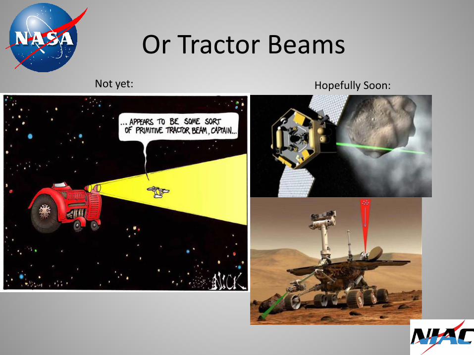
Or Tractor Beams Not yet: Hopefully Soon:
Tractor Beam Basics
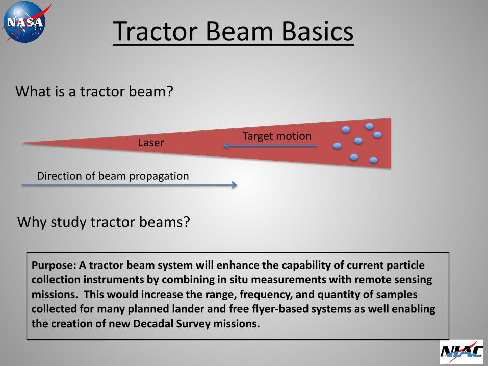
What is a tractor beam?
Why study tractor beams?
Direction of beam propagation
Target motion
Purpose: A tractor beam system will enhance the capability of current particle collection instruments by combining in situ measurements with remote sensing missions. This would increase the range, frequency, and quantity of samples collected for many planned lander and free flyer-based systems as well enabling the creation of new Decadal Survey missions.
Laser
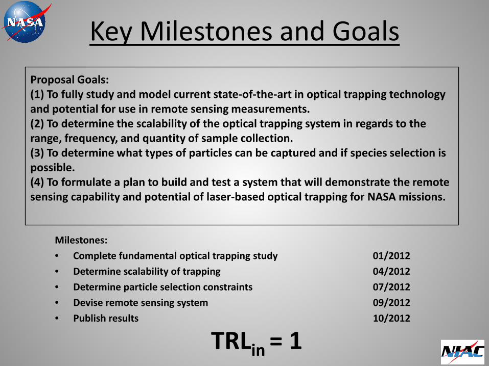
Key Milestones and Goals
Milestones:
• Complete fundamental optical trapping study 01/2012
• Determine scalability of trapping 04/2012
• Determine particle selection constraints 07/2012
• Devise remote sensing system 09/2012
• Publish results 10/2012
TRLin = 1
Proposal Goals: (1) To fully study and model current state-of-the-art in optical trapping technology and potential for use in remote sensing measurements. (2) To determine the scalability of the optical trapping system in regards to the range, frequency, and quantity of sample collection. (3) To determine what types of particles can be captured and if species selection is possible. (4) To formulate a plan to build and test a system that will demonstrate the remote sensing capability and potential of laser-based optical trapping for NASA missions.
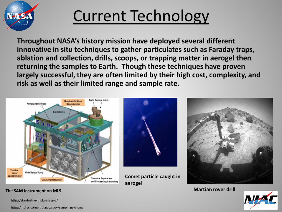
Current Technology Throughout NASA’s history mission have deployed several different innovative in situ techniques to gather particulates such as Faraday traps, ablation and collection, drills, scoops, or trapping matter in aerogel then returning the samples to Earth. Though these techniques have proven largely successful, they are often limited by their high cost, complexity, and risk as well as their limited range and sample rate.
Comet particle caught in aerogel
The SAM instrument on MLS Martian rover drill
http://stardustnext.jpl.nasa.gov/
http://msl-scicorner.jpl.nasa.gov/samplingsystem/

Mars Science Lab (MSL) Robotic Arm
Robotic Sample Arm
Turret-mounted devices on the end of the MSL robotic arm: drill, brush, soil scoop, sample processing device (sieves, portioners), and the two contact science instruments, APXS and MAHLI.
http://msl-scicorner.jpl.nasa.gov/samplingsystem/
http://msl-scicorner.jpl.nasa.gov/samplingsystem/
Mars Science Lab Sample Collection
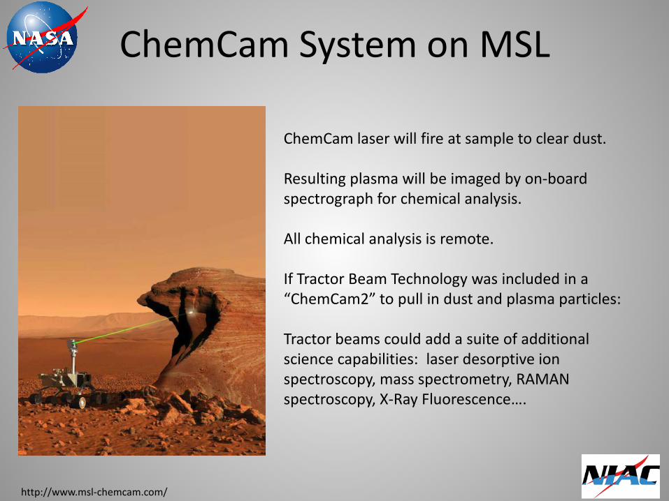
ChemCam laser will fire at sample to clear dust. Resulting plasma will be imaged by on-board spectrograph for chemical analysis. All chemical analysis is remote. If Tractor Beam Technology was included in a “ChemCam2” to pull in dust and plasma particles: Tractor beams could add a suite of additional science capabilities: laser desorptive ion spectroscopy, mass spectrometry, RAMAN spectroscopy, X-Ray Fluorescence….
http://www.msl-chemcam.com/
ChemCam System on MSL
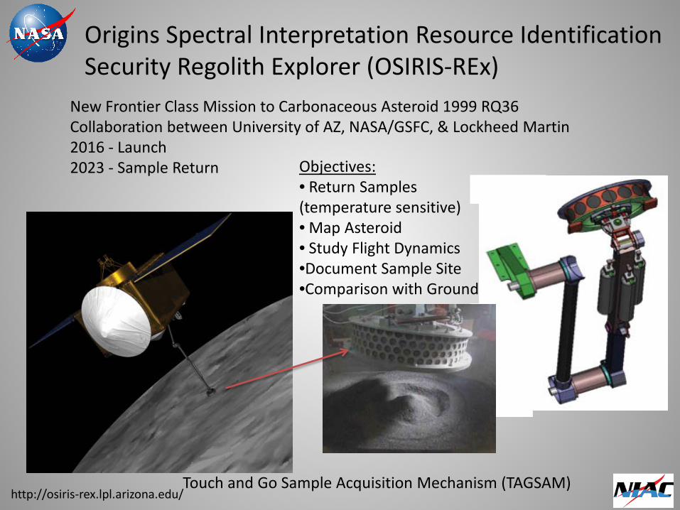
Origins Spectral Interpretation Resource Identification Security Regolith Explorer (OSIRIS-REx)
New Frontier Class Mission to Carbonaceous Asteroid 1999 RQ36 Collaboration between University of AZ, NASA/GSFC, & Lockheed Martin 2016 - Launch 2023 - Sample Return
http://osiris-rex.lpl.arizona.edu/
Objectives: • Return Samples (temperature sensitive) • Map Asteroid • Study Flight Dynamics •Document Sample Site •Comparison with Ground
Touch and Go Sample Acquisition Mechanism (TAGSAM)
OSIRIS-Rex TAGSAM Sequence
http://osiris-rex.lpl.arizona.edu/
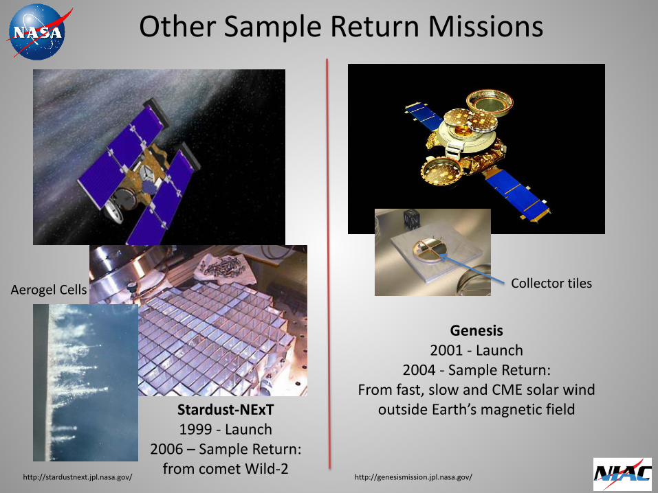
Other Sample Return Missions
Stardust-NExT 1999 - Launch
2006 – Sample Return: from comet Wild-2
http://stardustnext.jpl.nasa.gov/
Genesis 2001 - Launch
2004 - Sample Return: From fast, slow and CME solar wind
outside Earth’s magnetic field
http://genesismission.jpl.nasa.gov/
Aerogel Cells Collector tiles
Optical Trapping for Tractor Beams: Initial Study
• Bessel Beams
• Optical Pipeline
• Optical Conveyor Belt
• Helix Beam
• Self Focusing Trap
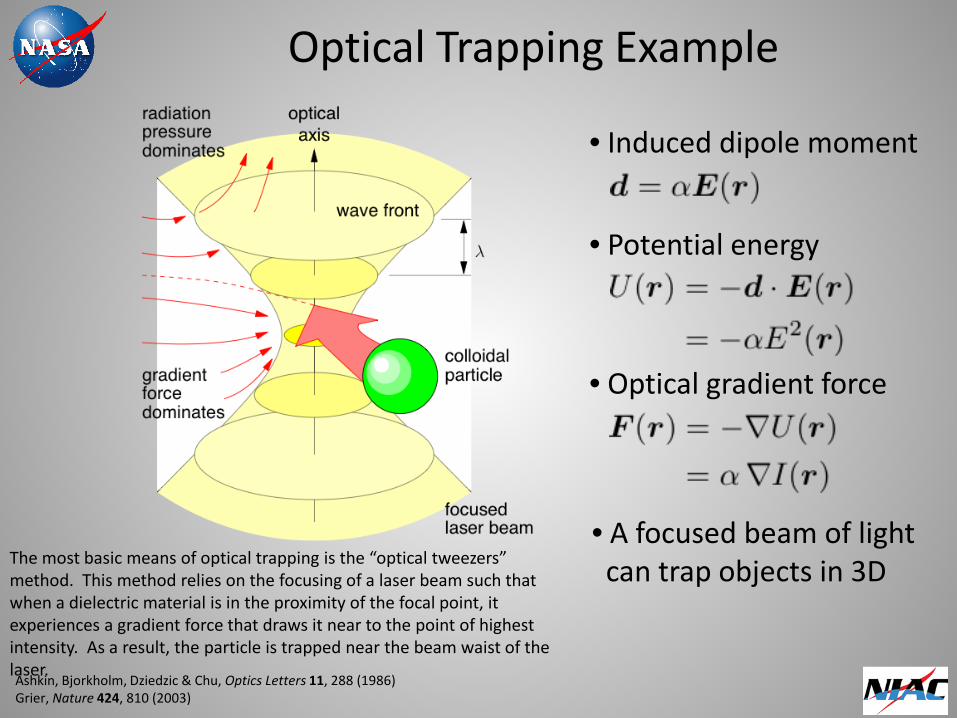
Optical Trapping Example
Ashkin, Bjorkholm, Dziedzic & Chu, Optics Letters 11, 288 (1986) Grier, Nature 424, 810 (2003)
• Induced dipole moment
• Potential energy
• Optical gradient force
• A focused beam of light can trap objects in 3D The most basic means of optical trapping is the “optical tweezers”
method. This method relies on the focusing of a laser beam such that when a dielectric material is in the proximity of the focal point, it experiences a gradient force that draws it near to the point of highest intensity. As a result, the particle is trapped near the beam waist of the laser.

Scattering From Bessel Beam
Θ
Chen, J., Ng, J., Lin, Z. & Chan, C. T. Nature Photon. 5, 531–534 (2011)
Optical Force
Scattering
Incoming Focused Bessel Beam
-Plane waves acting on multi-poles focus scattering in one direction -Transverse Bessel beam profile creates scattering with high order multipole interference -Radiation forces go to zero As angle Θ increases -Forward scattering stays finite and overcomes other forces creating net force back along the beam propagation -Scattering force is dependent on particle size -Possible use for selective filtering of targets
Target
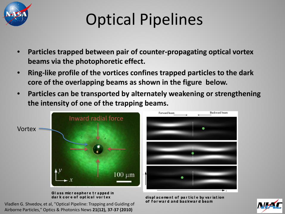
Optical Pipelines
• Particles trapped between pair of counter-propagating optical vortex beams via the photophoretic effect.
• Ring-like profile of the vortices confines trapped particles to the dark core of the overlapping beams as shown in the figure below.
• Particles can be transported by alternately weakening or strengthening the intensity of one of the trapping beams.
Vladlen G. Shvedov, et al, "Optical Pipeline: Trapping and Guiding of Airborne Particles," Optics & Photonics News 21(12), 37-37 (2010)
Inward radial force
Vortex
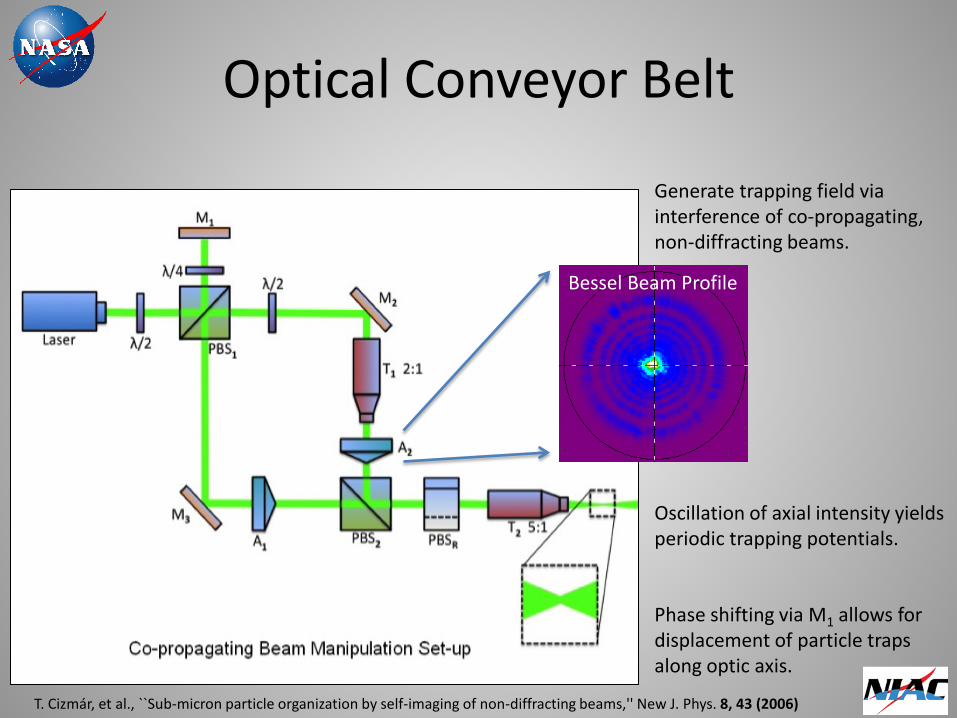
Optical Conveyor Belt
Generate trapping field via interference of co-propagating, non-diffracting beams.
Bessel beam profile
Phase shifting via M1 allows for displacement of particle traps along optic axis.
Oscillation of axial intensity yields periodic trapping potentials.
Bessel Beam Profile
T. Cizmár, et al., ``Sub-micron particle organization by self-imaging of non-diffracting beams,'' New J. Phys. 8, 43 (2006)
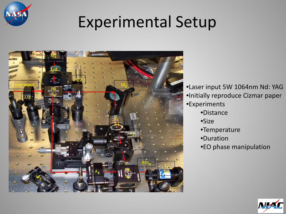
Experimental Setup
Laser Input
M1
M2
M3
λ/2
PBSR
PBS2
T2 3:1 A1
PBS1
T1 2:1
λ/4
λ/2
A2
•Laser input 5W 1064nm Nd: YAG •Initially reproduce Cizmar paper •Experiments
•Distance •Size •Temperature •Duration •EO phase manipulation
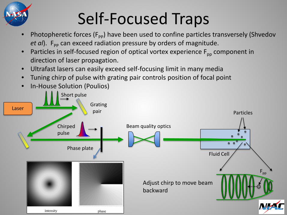
Self-Focused Traps
Laser
Phase plate Fluid Cell
Particles
Fpp
Grating pair
• Photopheretic forces (FPP) have been used to confine particles transversely (Shvedov et al). FPP can exceed radiation pressure by orders of magnitude.
• Particles in self-focused region of optical vortex experience Fpp component in direction of laser propagation.
• Ultrafast lasers can easily exceed self-focusing limit in many media • Tuning chirp of pulse with grating pair controls position of focal point • In-House Solution (Poulios)
Chirped pulse
Adjust chirp to move beam backward
Beam quality optics
Short pulse
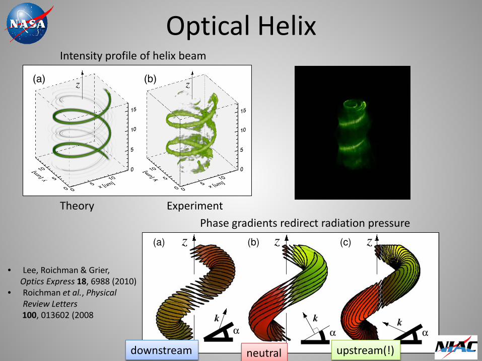
Optical Helix
• Lee, Roichman & Grier, Optics Express 18, 6988 (2010) • Roichman et al., Physical
Review Letters 100, 013602 (2008
Theory Experiment
Phase gradients redirect radiation pressure
downstream neutral upstream(!)
Intensity profile of helix beam
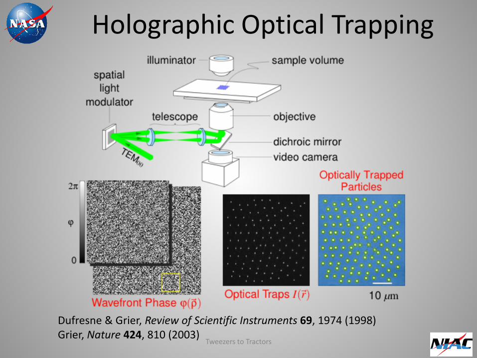
Dufresne & Grier, Review of Scientific Instruments 69, 1974 (1998) Grier, Nature 424, 810 (2003)
Holographic Optical Trapping
Tweezers to Tractors
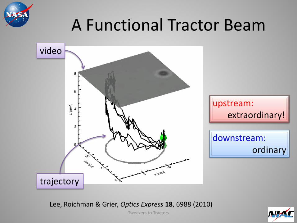
A Functional Tractor Beam
Lee, Roichman & Grier, Optics Express 18, 6988 (2010)
upstream: extraordinary!
video
trajectory
Tweezers to Tractors
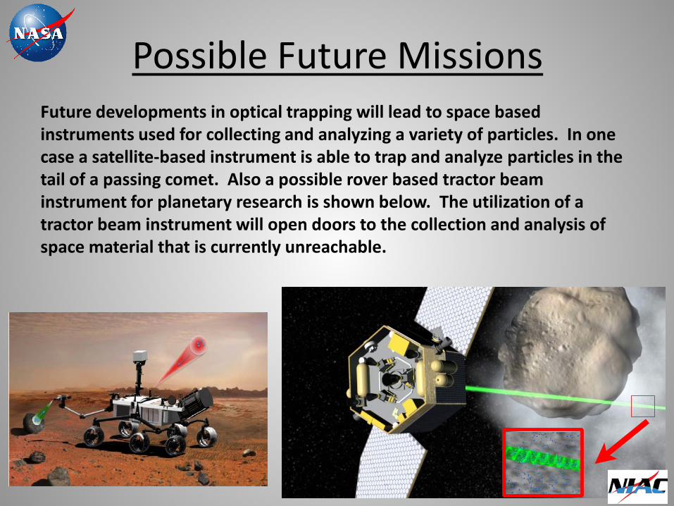
Possible Future Missions Future developments in optical trapping will lead to space based instruments used for collecting and analyzing a variety of particles. In one case a satellite-based instrument is able to trap and analyze particles in the tail of a passing comet. Also a possible rover based tractor beam instrument for planetary research is shown below. The utilization of a tractor beam instrument will open doors to the collection and analysis of space material that is currently unreachable.
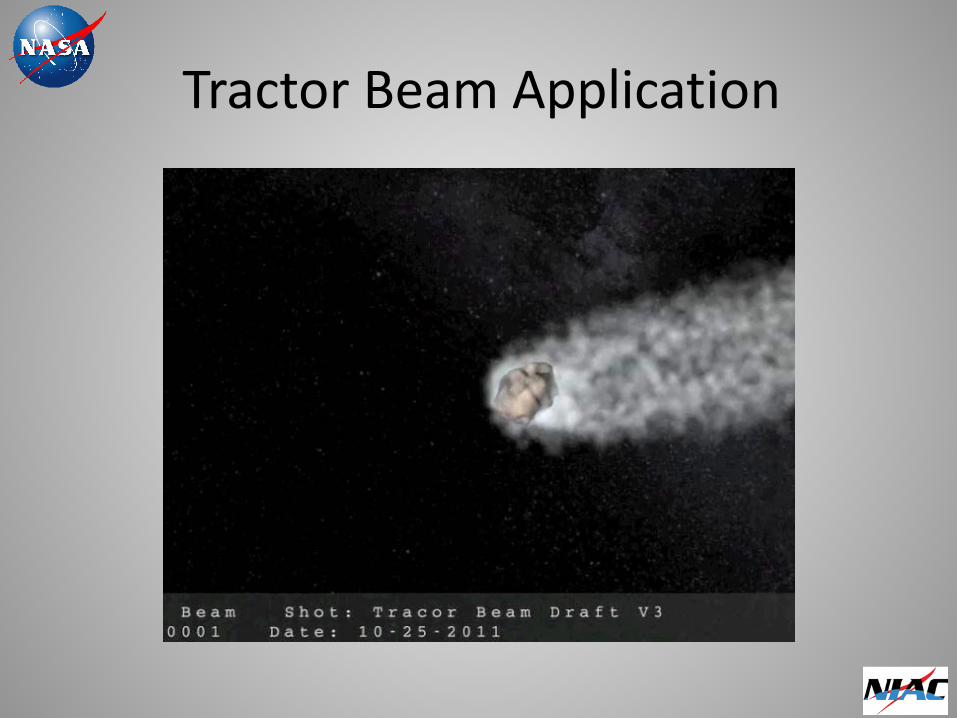
Tractor Beam Application
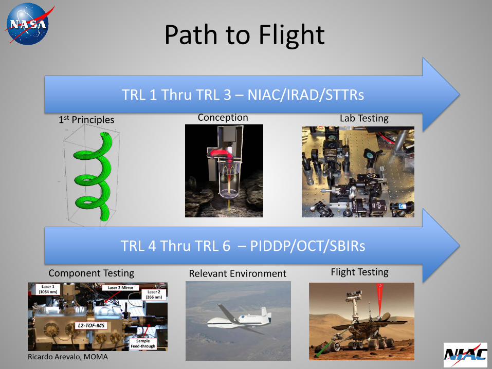
Path to Flight
TRL 1 Thru TRL 3 – NIAC/IRAD/STTRs
TRL 4 Thru TRL 6 – PIDDP/OCT/SBIRs
Conception Lab Testing
Component Testing Relevant Environment
1st Principles
Flight Testing
Ricardo Arevalo, MOMA
Impact of Tractor Beams for NASA: Manned, Robotic, and Commercial
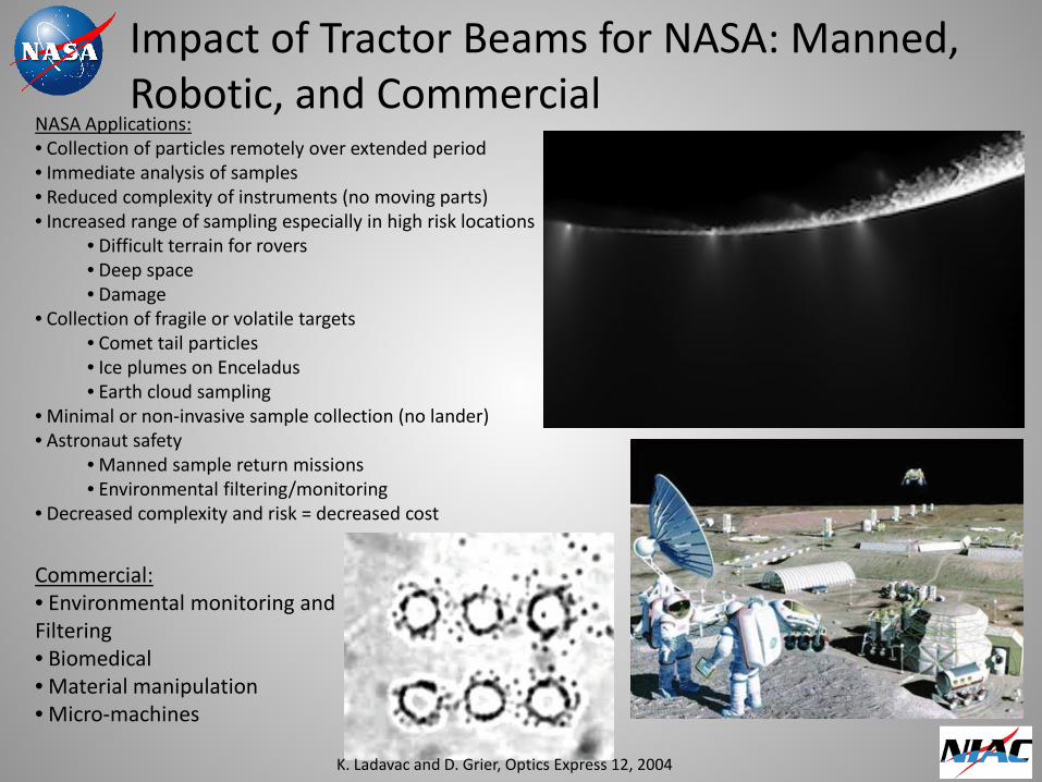
Commercial: • Environmental monitoring and Filtering • Biomedical • Material manipulation • Micro-machines
NASA Applications: • Collection of particles remotely over extended period • Immediate analysis of samples • Reduced complexity of instruments (no moving parts) • Increased range of sampling especially in high risk locations
• Difficult terrain for rovers • Deep space • Damage
• Collection of fragile or volatile targets • Comet tail particles • Ice plumes on Enceladus • Earth cloud sampling
• Minimal or non-invasive sample collection (no lander) • Astronaut safety
• Manned sample return missions • Environmental filtering/monitoring
• Decreased complexity and risk = decreased cost
K. Ladavac and D. Grier, Optics Express 12, 2004
Status/Future Plans
Completed initial study Engaged tractor beam academic community Limitations of system is largely understood • Study of particle selection underway • Communicating with NASA science community
to devise systems • Develop partnerships with tractor beam
community • Experiment with self focusing and optical
pipeline systems
Conclusions/Acknowledgements
• Tractor beams are not only possible but currently exist in the lab (with important limits)
• With proper funding and effort optical traps can adapted for practical space applications
• By partnerships with private and academic trapping communities, NASA is in position to nurture a new technology that can change the way sample collection science is achieved
Thanks to: NASA NIAC Program, Dr. David Grier, David Ruffner, Dr. Cizmar, Dr. Shvedov, Dr. Chen, NASA-OCT, GSFC-OCT, GSFC-Code 550-OCT, GSFC-Code 554, Dr. Jason Dworkin, Dr. Rick Arevalo, GSFC-MOMA Science Team, Dr. Jack Bufton


![Programmable Interplanetary Networks - UvA · recent tests such as the Interplanetary Internet[3], showing the rst approaches to a so called InterPlanetary Network (IPN). With the](https://static.fdocuments.in/doc/165x107/5f0461a37e708231d40db1e7/programmable-interplanetary-networks-uva-recent-tests-such-as-the-interplanetary.jpg)