LASER ALIGNMENT TOOLS - caglayanlar.com.tr · Shaft Alignment – LAS-Set Traditional Shaft...
12
LASER ALIGNMENT TOOLS SHAFT-SET + BELT-SET SUBSCRIBE TO NSK NEWSLETTER SUBSCRIBE TO NSK NEWSLETTER
Transcript of LASER ALIGNMENT TOOLS - caglayanlar.com.tr · Shaft Alignment – LAS-Set Traditional Shaft...
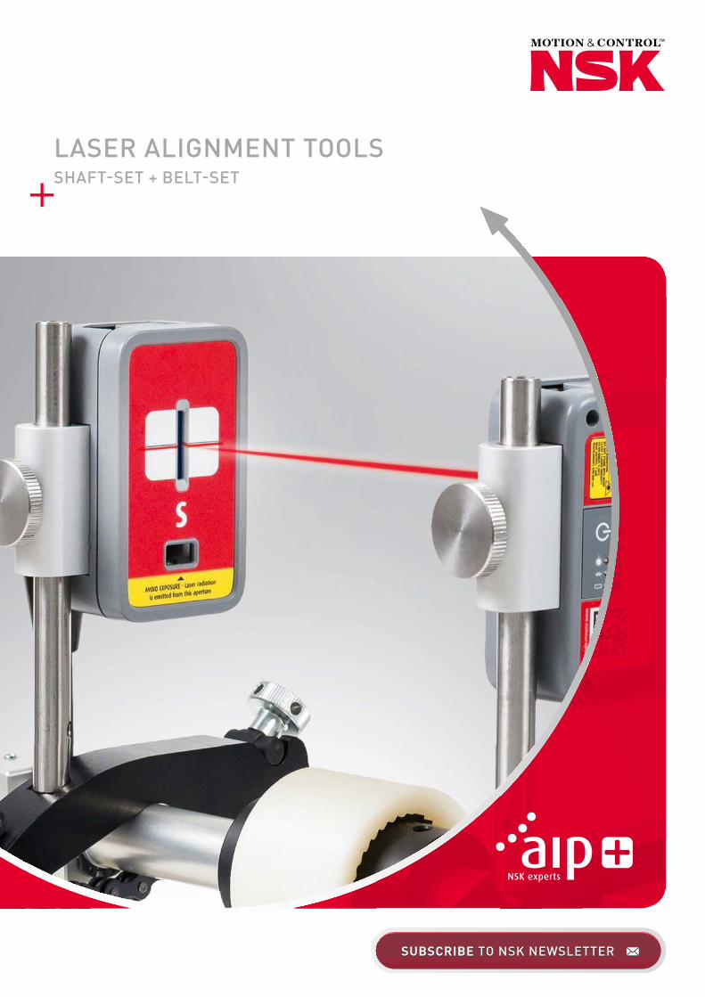
LASER ALIGNMENT TOOLS SHAFT-SET + BELT-SET
SUBSCRIBE TO NSK NEWSLETTERSUBSCRIBE TO NSK NEWSLETTER
2
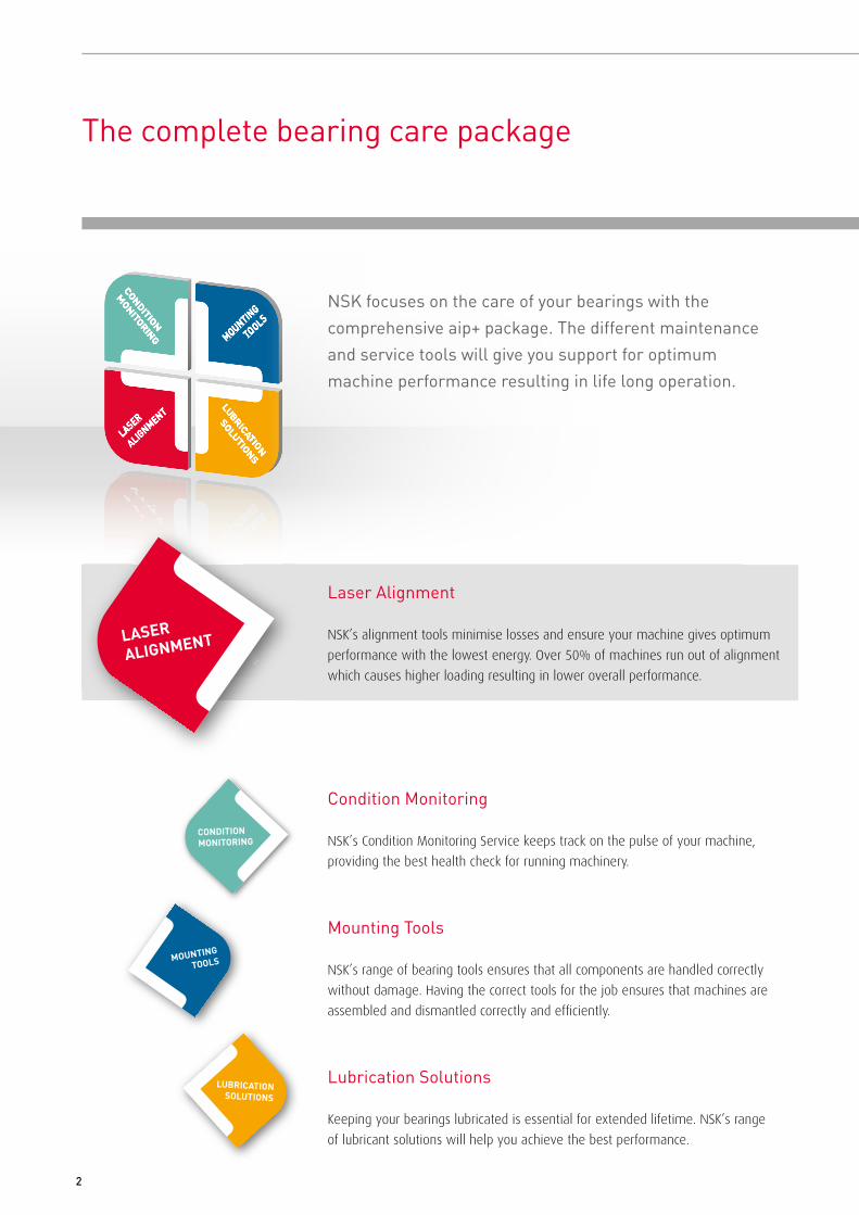
The complete bearing care package
LASER
ALIGNMENT
MOUNTING
TOOLS
LUBRICATIO
BRICATIO
BRICAN
SOLUTIONS
LALASER
ALIGNMEN
ATIONLUTIONS
CONDITION
MONITORING
CONDITIONMONITORING
LASE
RAL
IGNM
ENT
MOU
NTIN
GTO
OLS
LUBRICATIONSOLUTIONS
CONDITION
MONITORING
LASERALIGNMENT
MOUNTINGTOOLS
LUBRICATION
SOLUTIONS
CONDITIONMONITORING
LASE
RAL
IGNM
ENT
MOU
NTIN
GTO
OLS
LUBRICATIONSOLUTIONS
ENT
MMO
MO
MOUNTINGNG
TOTOOLS
LUBRICATIOSOLUTI
COCONDITIOITIONN
MOMONI OOTOTORIR NG
CONDITION
MONITORING
LASERALIGNMENT
MOUNTINGTOOLS
LUBRICATION
SOLUTIONS
Condition Monitoring
NSK’s Condition Monitoring Service keeps track on the pulse of your machine, providing the best health check for running machinery.
Mounting Tools
NSK’s range of bearing tools ensures that all components are handled correctly without damage. Having the correct tools for the job ensures that machines are assembled and dismantled correctly and efficiently.
Lubrication Solutions
Keeping your bearings lubricated is essential for extended lifetime. NSK’s range of lubricant solutions will help you achieve the best performance.
NSK focuses on the care of your bearings with the comprehensive aip+ package. The different maintenance and service tools will give you support for optimum machine performance resulting in life long operation.
Laser Alignment
NSK’s alignment tools minimise losses and ensure your machine gives optimum performance with the lowest energy. Over 50% of machines run out of alignment which causes higher loading resulting in lower overall performance.

3
Why correct alignment is so important
NSK's Laser alignment equipment includes devices for both shaft and belt drive systems: › LAS-Set - Shaft › LAB-Set - Belt
Accurate alignment is difficult to achieve using traditional methods. In today’s challenging world, fast and precise set up of machinery is a prerequisite and this is where laser alignment tools comes into play. Alignment of rotating machinery components is extremely important for correct operation and optimum power usage. However, this is not often appreciated and over half of all installations are not aligned correctly. This results in machines that don’t perform to their potential causing early wear and failure of components such as bearings, gears, seals and couplings. But not only this, higher energy usage and larger maintenance costs are encountered.
Benefits of Laser Alignment
› Increased bearing lifetime› Increased machinery uptime, efficiency and productivity› Reduced wear on machine components
› Reduced energy usage› Smooth running with reduced vibration and noise› Quick operation, measurement and adjustment
4
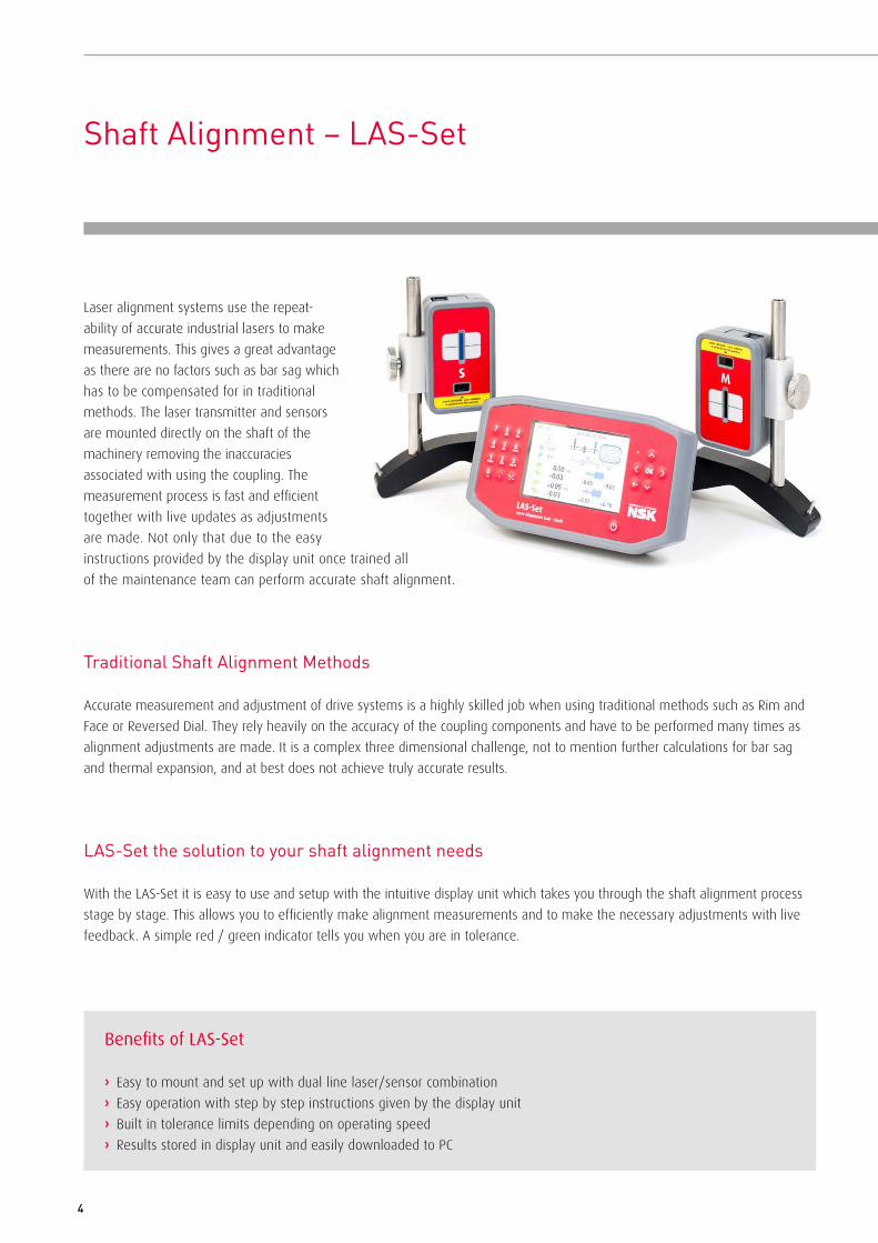
Shaft Alignment – LAS-Set
Traditional Shaft Alignment Methods
Accurate measurement and adjustment of drive systems is a highly skilled job when using traditional methods such as Rim and Face or Reversed Dial. They rely heavily on the accuracy of the coupling components and have to be performed many times as alignment adjustments are made. It is a complex three dimensional challenge, not to mention further calculations for bar sag and thermal expansion, and at best does not achieve truly accurate results.
LAS-Set the solution to your shaft alignment needs
With the LAS-Set it is easy to use and setup with the intuitive display unit which takes you through the shaft alignment process stage by stage. This allows you to efficiently make alignment measurements and to make the necessary adjustments with live feedback. A simple red / green indicator tells you when you are in tolerance.
Laser alignment systems use the repeat- ability of accurate industrial lasers to make measurements. This gives a great advantage as there are no factors such as bar sag which has to be compensated for in traditional methods. The laser transmitter and sensors are mounted directly on the shaft of the machinery removing the inaccuracies associated with using the coupling. The measurement process is fast and efficient together with live updates as adjustments are made. Not only that due to the easy instructions provided by the display unit once trained all of the maintenance team can perform accurate shaft alignment.
Benefits of LAS-Set
› Easy to mount and set up with dual line laser/sensor combination› Easy operation with step by step instructions given by the display unit› Built in tolerance limits depending on operating speed› Results stored in display unit and easily downloaded to PC

5
All in One Box
The LAS-Set is supplied in a hard wearing carry case and all the parts needed for your shaft alignment tasks are con-tained within. The system uses rechargeable batteries which will give you up to 8 hours continuous use. However the system does also include a power management and resume function to save battery life. Each of the parts is charged using a standard mini USB port and the charger is included in the case.
The Alignment Process with LAS-Set
The easy to use software guides you through each stage of the alignment process› Softfoot - Checking the motor mounting is stable and not causing deflection› Tolerance Selection - Inbuilt recommended alignment tolerances based on
speed or enter your own› Dimensional Input - Input of the sensor positions relative to the coupling
and motor feet› Initial Measurement - Shaft Alignment in 3 positions 90° apart› Adjustment - Guided adjustment of the motor with live feedback› Final Measurement - Recorded alignment condition after adjustment
Two Sensor units with two laser beams
The LAS-Set tool has two sensor units with integrated sensor technology and line lasers allowing quick set up without the need for rough adjustment and laser targeting even for larger angular misalignments. The sensor units feature wireless communication paired to the display unit. This gives more freedom when moving around the machine, particularly when using the live results for adjusting the motor. The sensors are positively mounted to the shaft using the precision V-brackets and chain clamp allowing for a large range of shaft sizes.

6
Using the LAS-Set is so easy – the software is icon based and intuitive, guiding you from one step to the next.
Software operation – LAS-Set
Features› Both shaft positions are monitored simultaneously› Live values during adjustment› Measures once, adjustment control in two directions› Adaptive and icon based user interface› Colour screen› Colour coded measurement results
› All digital system› 2nd generation sensor – allows for high repeatability› Unparalleled digital signal control› Integrated wireless units› Compact sensor units› Compatible with all standard 5V mini USB chargers,
battery life extenders and 12V car adapter
Horizontal shaft alignment
Determine and correct the relative position of two horizontally mounted machines that are connected, such as a motor and a pump, so that the rotational centres of the shafts are collinear.
Softfoot Check
This function checks if there is a soft foot condition, i.e. when the motor is not positioned firmly on all its feet.
Memory Manager
Measurements can be organised in folders and subfolders. Single measurements and/or complete data structures can be copied to a PC via USB connector.
Power Management SystemThe LAS-Set has exceptional power management with an integrated resume function. This function automatically saves all critical data if and when it goes into energy saving mode or if the battery goes flat. Once the system is switched on again, the program restarts from where you left off.
7
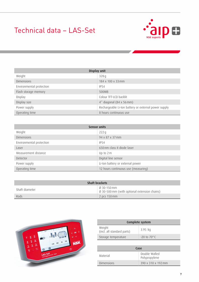
Technical data – LAS-Set
Display unit
Weight 328 g
Dimensions 184 x 100 x 33 mm
Environmental protection IP54
Flash storage memory 500MB
Display Colour TFT-LCD backlit
Display size 4’’ diagonal (84 x 56 mm)
Power supply Rechargeable Li-Ion battery or external power supply
Operating time 8 hours continuous use
Sensor units
Weight 222 g
Dimensions 94 x 87 x 37 mm
Environmental protection IP54
Laser 650 nm class II diode laser
Measurement distance Up to 2 m
Detector Digital line sensor
Power supply Li-Ion battery or external power
Operating time 12 hours continuous use (measuring)
Shaft brackets
Shaft diameterØ 30-150 mm Ø 30-500 mm (with optional extension chains)
Rods 2 pcs 150 mm
Complete system
Weight (incl. all standard parts)
3.95 kg
Storage temperature -20 to 70° C
Case
MaterialDouble Walled Polypropylene
Dimensions 390 x 310 x 192 mm

8
Belt Alignment – LAB-Set
Correct alignment of belt drives is increasingly important in an environment where machine performance and maintenance costs are key considerations. Pulley misalignment can result in unnecessary forces being applied to the machinery leading to increased wear and vibration causing premature bearing failure and thereby costly machine downtime.
Traditional belt alignment methods
Typically this involves the use of a straight edge or even string placed on the pulley side. However this is limited by the length of the straight edge and assumes that the pulley side is clean, rust free and parallel to the pulley V-grooves. This method usually does not result in an accurate alignment.
Correct alignment
Parallel
Angular horizontal
Angular vertical
Types of misalignment

9
LAB-Set – the solution to all your belt alignment needs
NSK´s Laser alignment tool for belts (LAB-Set) enables truly accurate alignment as the laser heads are fitted directly into the pulley V-grooves. The LAB-Set is very easy to use and allows adjustment with the belt in place. With the LAB-Set, you are never in doubt whether your belt transmissions are aligned or not. By using the V-grooves as reference, you will achieve precise alignment which reduces belt wear, bearing failures and vibration.
Benefits of LAB-Set
› Increased bearing lifetime› Increased machinery uptime, efficiency and productivity› Reduced wear of pulleys and belts› Reduced unplanned downtime
› Reduced costs for component replacement› Reduced friction and hence energy consumption› Reduced vibration and noise

10
AVOID EXPOSURE - Laser radiationis em
itted from this aperture
AVOI
D EX
POSU
RE -
Lase
r rad
iatio
nis
em
itted
from
this
ape
rtur
e
AVOID EXPOSURE - Laser radiationis em
itted from this aperture
AVOI
D EX
POSU
RE -
Lase
r rad
iatio
nis
em
itted
from
this
ape
rtur
e
AVOID EXPOSURE - Laser radiationis em
itted from this aperture
AVOI
D EX
POSU
RE -
Lase
r rad
iatio
nis
em
itted
from
this
ape
rtur
e
AVOID EXPOSURE - Laser radiationis em
itted from this aperture
AVOI
D EX
POSU
RE -
Lase
r rad
iatio
nis
em
itted
from
this
ape
rtur
e
AVOID EXPOSURE - Laser radiationis em
itted from this aperture
AVOI
D EX
POSU
RE -
Lase
r rad
iatio
nis
em
itted
from
this
ape
rtur
e
AVOID EXPOSURE - Laser radiationis em
itted from this aperture
AVOI
D EX
POSU
RE -
Lase
r rad
iatio
nis
em
itted
from
this
ape
rtur
e
AVOID EXPOSURE - Laser radiationis em
itted from this aperture
AVOI
D EX
POSU
RE -
Lase
r rad
iatio
nis
em
itted
from
this
ape
rtur
e
AVOID EXPOSURE - Laser radiationis em
itted from this aperture
AVOI
D EX
POSU
RE -
Lase
r rad
iatio
nis
em
itted
from
this
ape
rtur
e
AVOID EXPOSURE - Laser radiationis em
itted from this aperture
AVOI
D EX
POSU
RE -
Lase
r rad
iatio
nis
em
itted
from
this
ape
rtur
e
Two transmitters with visible red laser line
The LAB-Set comes with two line laser transmitters, each equipped with two spring loaded guides which fit into the pulley grooves. The use of two laser transmitters with integrated targets makes it very easy to find out what kind of alignment is required. Parallel offset, angular error and twist are instantly visible to the operator. Within a few minutes the operator can determine if the machine requires alignment or not. This is far more accurate than single laser head types.
Mounting of the transmitters
The LAB-Set units are very easily mounted on the pulleys, regardless of the condition of the pulley side faces. The spring action probe finds the centre of the belt groove. The built-in industrial magnets snap the units to the pulley with a perfect fit. The LAB-Set is equipped with various sized removable guides to fit standard groove profiles sizes A-E (6 – 40 mm). Additional guides for alignment of timing belts are available as accessories.
The alignment process with the LAB-Set
The visible red laser line makes it easy to determine the position of your belt driven machines. The alignment process is as easy as the mounting. Just turn on the lasers and look at the opposite mounted unit. The laser shows as a line on the target label as in the illustration to the right. If necessary, adjust your machine position until the laser lines are aligned with the centre mark. This is done for both units which ensures accurate alignment at a distance up to 6m.
The LAB-Set units are very easily mounted on the pulleys. The spring action probe finds the centre of the belt groove. The built-in industrial magnets snap the units to the pulley in a perfect fit. Optional equipment makes it possible to align timing belt driven machines.

11
Technical data – LAB-Set
Measuring units
Housing material Extruded aluminum (molded ABS cover)
Operating temperature 0 to 40°C
Relative humidity 10 – 90%
Weight 300g
Dimensions 61 x 77 x 61mm
Laser 600 – 650 nm class II diode laser
Laser line fan angle 90°
Laser power < 1mW
Measurement distance 50 – 6000mm
Measurement accuracy Better than 0.5mm or 0.2 degrees
Pulley diameter range From 75mm and larger (standard)
Pulley belt groove width 6 – 40mm (standard)
Power supply (battery) 2 pcs of LR03 (AAA) 1.5V per unit
Operating time 20 hours of continuous operation
Laser safety See yellow label on unit
Complete system
Weight (incl. all standard parts)
1.6 kg
Storage temperature -20 to 70° C
Case
MaterialDouble Walled Polypropylene
Dimensions 300 x 275 x 110 mm

Please also visit our website: www.nskeurope.com Global NSK: www.nsk.com
UK
NSK UK Ltd.
Northern Road, Newark
Nottinghamshire NG24 2JF
Tel. +44 (0) 1636 605123
Fax +44 (0) 1636 643276
France & Benelux
NSK France S.A.S.
Quartier de l’Europe
2, rue Georges Guynemer
78283 Guyancourt Cedex
Tel. +33 (0) 1 30573939
Fax +33 (0) 1 30570001
Germany, Austria,
Switzerland, Nordic
NSK Deutschland GmbH
Harkortstraße 15
40880 Ratingen
Tel. +49 (0) 2102 4810
Fax +49 (0) 2102 4812290
Italy
NSK Italia S.p.A.
Via Garibaldi, 215
20024 Garbagnate
Milanese (MI)
Tel. +39 02 995 191
Fax +39 02 990 25 778
Middle East
NSK Bearings Gulf Trading Co.
JAFZA View 19, Floor 24 Office 2/3
Jebel Ali Downtown,
PO Box 262163
Dubai, UAE
Tel. +971 (0) 4 804 8205
Fax +971 (0) 4 884 7227
Poland & CEE
NSK Polska Sp. z o.o.
Warsaw Branch
Ul. Migdałowa 4/73
02-796 Warszawa
Tel. +48 22 645 15 25
Fax +48 22 645 15 29
Russia
NSK Polska Sp. z o.o.
Russian Branch
Office I 703, Bldg 29,
18th Line of Vasilievskiy Ostrov,
Saint-Petersburg, 199178
Tel. +7 812 3325071
Fax +7 812 3325072
South Africa
NSK South Africa (Pty) Ltd.
25 Galaxy Avenue
Linbro Business Park
Sandton 2146
Tel. +27 (011) 458 3600
Fax +27 (011) 458 3608
Spain
NSK Spain, S.A.
C/ Tarragona, 161 Cuerpo Bajo
2a Planta, 08014 Barcelona
Tel. +34 93 2892763
Fax +34 93 4335776
Turkey
NSK Rulmanları Orta Doğu Tic. Ltd. Şti
19 Mayıs Mah. Atatürk Cad.
Ulya Engin İş Merkezi No: 68/3 Kat. 6
P.K.: 34736 - Kozyatağı - İstanbul
Tel. +90 216 4777111
Fax +90 216 4777174
NSK Sales Offices – Europe, Middle East and Africa
Every care has been taken to ensure the infor mation in this publication is accurate but no liability can be accepted for any errors or omissions. © Copyright NSK 2016. The contents of this publication are the copyright of the publishers. Ref: LA/A/E/06.16.