laser
15
MPC03 User Manual(Rev1.0) I User Manual MPC03LV/LH Rev. 1.0
description
laser
Transcript of laser

MPC03 User Manual(Rev1.0)
I
User Manual
MPC03LV/LH
Rev. 1.0

MPC03 User Manual(Rev1.0)
II
Table of Contents
1 DUAL-AXIS STEPPING SYSTEM .................................................................................... 1
1.1System Description..................................................................................................................... 1 1.2Connection Diagram.................................................................................................................. 1
2 CONNECT MOTION CONTROLLER TO LASER POWER SUPPLIES.................................... 2 2.1 Connection Diagram.............................................................................................................. 2
3 CONNECTION OF MPC03 ............................................................................................... 3 4 CONNECTION OF ORIGIN AND LIMIT SIGNALS................................................................ 5
4.1 Origin Switches ...................................................................................................................... 5 4.2 Limit Switches ........................................................................................................................ 7
5CONNECTION OF CONTROL PANEL FUNCTIONS............................................................... 9 5.1 Connection of Jog Key Switches ............................................................................................... 9 5.2 Connection of Other Function Key Switches .......................................................................... 10
APPENDIX .........................................................................................12
PINS ARRAY.................................................................................................................... 12
MPC03 User Manual(Rev1.0)
1
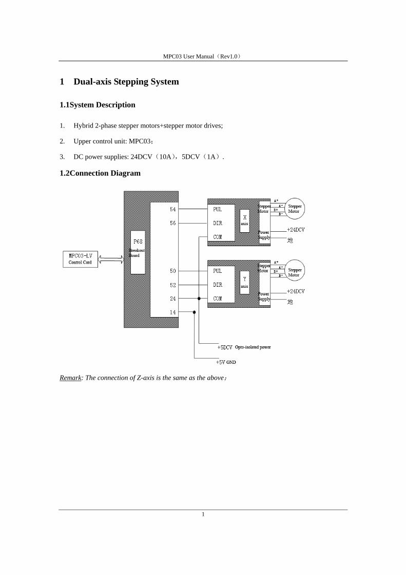
1 Dual-axis Stepping System
1.1System Description
1. Hybrid 2-phase stepper motors+stepper motor drives;
2. Upper control unit: MPC03;
3. DC power supplies: 24DCV(10A),5DCV(1A).
1.2Connection Diagram
Remark: The connection of Z-axis is the same as the above;

MPC03 User Manual(Rev1.0)
2
2 Connect Motion Controller to Laser Power Supplies
2.1 Connection Diagram
2.1.1 PWM Laser Power
Remark1: Pins descriptions of different power supplies will differs. Please confirm with your supplier
before connecting.
Remark2:The diagram above describes the connection when signals are high-voltage effective. For
low voltage effective signals, connect Pin15 of P68 to Pin2 of the power supply.

MPC03 User Manual(Rev1.0)
3
2.1.2 Laser power supply controlled by voltage-power
Remark1: Pins descriptions of different power supplies will differs, please confirm with your supplier
before connecting.
Remark2: FV100 module is used to convert the pulse signals to analogue voltage signals;
Remark3:The diagram above describes the connection when signals are high-voltage effective. For
low voltage level, you should connect Pin15 to Pin2 of the power supply.
Remark4: P18 is FRQ pin for MPC03-LV, if you are using MPC03-LH, the corresponding pin should
be P17.
3 Connection of MPC03
The digital inputs (limit, deceleration, home, and external alarm) of MPC03 control card can be
contact switches and NPN-output proximity sensor switches. Refer to Fig 3.1.
Fig 3.2 describes the connection of pulse+direction signals.
Fig 3.3 describes the connection of external encoder signals.

MPC03 User Manual(Rev1.0)
4
24DCV
MPC03Control Card External signal
Opto-isolated power GND
24DCV
a.Contact Switches b.NPN-ouput proximity switches
Fig 3.1 Connection of Digital Inputs
26LS32 Or Equivalent circuit
MPC03 Control Card Drives a.Connection of differential signal
MPC03 Control Card Drives b.Connection of single-port signal
+ +
- - GND
+5V
+
-
Fig3.2 Connection of Pul/Dir Outputs
MPC03 Control Card Encoder Signal
GND
MPC03 Control Card Encoder Signal
Encoder Power +5V
+
-
+
-
a.Connection of single-port signal b.Connection of differential signal
Fig3.3 Connection of Encoder Feedback Inputs
MPC03Control Card External signal
Opto-isolated power GND
Pull-up resistor

MPC03 User Manual(Rev1.0)
5
4 Connection of Origin and Limit Signals
4.1 Origin Switches
4.1.1 Origin Switch Connection (low-voltage effective)
Remark1: ORG Switch should be connected to “5V opto-isolated power GND”
Remark2: The diagram above describes the connection when digital signals are low-voltage effective.
Remark3: If you don’t want origin switches, connect these pins to +12-+24DCV opto-isolated power
output from the controller OR disconnect these pins.

MPC03 User Manual(Rev1.0)
6
4.1.2 Origin Switch Connection (high-voltage effective)
Remarks1: ORG Switch should be connected to “5V opto-isolated power GND”
Remark2: The diagram above describes the connection when signals are high voltage effective (User
can set signals low-voltage effective or high-voltage effective with LaserCut software).
Remark3: If you don’t want origin switch, connect these pins to 12~+24V opto-isolated power GND.

MPC03 User Manual(Rev1.0)
7
4.2 Limit Switches
4.2.1 Limit Switch Connection (low-voltage effective)
Remarks1: Limit Switch should be connected to “5V opto-isolated power GND”
Remarks2: The diagram above describes the connection when signals are low-voltage effective.
Remarks3: If you don’t want limit switch, connect these pins to +12~+24DCV opto-isolated power OR
disconnect these pins.

MPC03 User Manual(Rev1.0)
8
4.2.2 Limit Switch Connection (high-voltage effective)
Remarks1: Limit Switch should be connected to “5V opto-isolated power GND”
Remarks2: The diagram above describes the connection when signals are high-voltage effective.
Remarks3: If you don’t want limit switch, connect these pins to 12~+24V opto-isolated power
GND.

MPC03 User Manual(Rev1.0)
9
5Connection of Control Panel Functions
5.1 Connection of Jog Key Switches
5.1.1 Negative Connection
Remarks1: Connect jog key switches to 5V GND, and then the corresponding positive inputs of
encoder to +5V opto-isolated power.

MPC03 User Manual(Rev1.0)
10
5.1.2 Positive Connection
Remarks1: Connect jog key switches to +5V opto-isolated power, and then the corresponding negative
inputs of encoder to 5V GND.
5.2 Connection of Other Function Key Switches
5.2.1Negative Connection
Move along edges

MPC03 User Manual(Rev1.0)
11
Remarks1: Connect function key switches connect to 5V GND, and then the corresponding positive
inputs of encoder to +5V opto-isolated power.
5.2.2Positive Connection
Remarks1: Connect function key switches to +5V opto-isolated power, and then the corresponding
negative inputs of encoder to 5V GND.
Move along edges

MPC03 User Manual(Rev1.0)
12
Appendix
Pins Array
Pin Name Description Pins Name Description
1 2
3 4
5 6
7 EA2+ +5V 8 EA2- Pause
9 EB2+ +5V
10 EB2- Back to origin
(Homing)
11 EZ2+ +5V 12 EZ2- Emergency stop
13 14 GND5 +5V GND
15 LASER Laser output 16
17 18 FRQ/PWMLaser power(for
MPC03-LV)
19 PUL2- Pulse 2- 20 PUL2+ Pulse 2+
21 DIR2- Direction 2- 22 DIR2+ Direction 2+
23 24 DCV5 +5DCV
25 26 ORG2 Origin 2
27 28 EL2+ Forward limit 2
29 30 EL2- Reverse limit 2
31 32 SD2+ Forward deceleration 2
33 34 SD2- Reverse deceleration 2
35 EA3+ +5V 36 EA3- Move downward
37 EB3+ +5V 38 EB3- Move rightward
39 EZ3+ +5V 40 EZ3- Move upward
41 EA4+ +5V 42 EA4- Move along edges
43 EB4+ +5V 44 EB4- Start/Continue
45 EZ4+ +5V 46 EZ4- Move leftwards-
47 48
49 PUL3- Pulse 3- 50 PUL3+ Pulse 3+
51 DIR3- Direction 3- 52 DIR3+ Direction 3+
53 PUL4- Pulse 4- 54 PUL4+ Pulse 4+
55 DIR4- Direction 4- 56 DIR4+ Direction 4+
57 DCV24 +24DCV 58 ALM External alarm input
59 ORG3 Origin 3 60 ORG4 Origin 4

MPC03 User Manual(Rev1.0)
13
61 EL3+ Forward limit 3 62 EL4+ Forward limit 4
63 EL3- Reverse limit 3 64 EL4- Reverse limit 4
65 SD3+ Forward deceleration 3 66 SD4+ Forward deceleration 4
67 SD3- Reverse deceleration 3 68 SD4- Reverse deceleration 4
Remark1: Connect FRQ/PWM to P17 if you are using MPC03-LH, and to P18 if you are using
MPC03-LV.