LaRonde Extension — mine design at three kilometres
14
Deep Mining 2010 — M. Van Sint Jan and Y. Potvin (eds) © 2010 Australian Centre for Geomechanics, Perth, ISBN 978-0-9806154-5-6 Deep Mining 2010, Santiago, Chile 3 LaRonde Extension — mine design at three kilometres F. Mercier-Langevin Agnico-Eagle Mines Ltd, Canada Abstract Agnico-Eagle’s flagship LaRonde Mine is exploiting a world-class Au-Ag-Cu-Zn-Pb massive sulphide lenses complex. It is located in the Abitibi Region of north-western Quebec, approximately 650 km northwest of Montreal. With 5 million ounces of gold in proven and probable reserves, LaRonde has one of the largest gold reserves of any mine operating in Canada. These reserves extend from surface down to 3,110 metres and remain open at depth. The 2,250 metre Penna Shaft, which is believed to be the deepest single-lift shaft in the Western Hemisphere, is used to hoist LaRonde's ore production of approximately 7,200 tonnes per day. Current mining operations are taking place at over 2,400 metres below surface. In 2006, the decision was taken to sink a winze in order to access the ore below 2,450 metres. The new #4 Shaft extends to a depth of approximately 2,840 metres below surface. With the use of ramps the mine will access reserves as deep as 3,110 metres. Production from Shaft No.4 is scheduled to begin late in 2011, with the full production rate reached in 2013. It is expected that the LaRonde Extension will extend the mine life well beyond 2020. Sinking a winze shaft and building all the necessary infrastructure of a mine at a depth of over 2.8 km poses unique challenges, some of which are discussed. 1 Introduction Located near the village of Preissac in Northern Quebec, the LaRonde Mine has been in operation since 1988. Over 600 employees are operating the complex, for an average production of 7,200 t per day. The 2,240 m deep Penna shaft is used to hoist the ore. Production is ongoing between Level 98 (980 m below surface) and Level 245 (2,450 m below surface). The LaRonde orebody is a world-class Au-Ag-Cu-Zn-Pb massive sulphide lenses complex (Figure 1). As of 2009, reserves at LaRonde total over 34 million tonnes of ore, for over 4.8 million ounces of gold (Agnico-Eagle Mines Ltd, 2010). At the planned mining rate, operations are expected to continue beyond 2023. Production from Level 215 (2,150 m below surface) and up is sent to the Penna shaft to be hoisted to surface using a combination of ore passes and trucking. All the ore extracted below shaft bottom down to 2,450 m has to be trucked up to 215 Level. The mine is currently undergoing an expansion at depth, the LaRonde Extension project. This expansion consists in the sinking of an internal Shaft (winze). Sinking of the #4 Shaft was completed in November 2009, and lateral development started on Level 278 and 282 in February of this year. The new shaft will enable the mine to extract reserves below 245 Level down to 311 Level (3,110 m below surface). This paper presents some of the challenges that have been overcome as well as challenges the mine has yet to tackle.
Transcript of LaRonde Extension — mine design at three kilometres

Deep Mining 2010 — M. Van Sint Jan and Y. Potvin (eds) © 2010 Australian Centre for Geomechanics, Perth, ISBN 978-0-9806154-5-6
Deep Mining 2010, Santiago, Chile 3
LaRonde Extension — mine design at three kilometres
F. Mercier-Langevin Agnico-Eagle Mines Ltd, Canada
Abstract Agnico-Eagle’s flagship LaRonde Mine is exploiting a world-class Au-Ag-Cu-Zn-Pb massive sulphide lenses complex. It is located in the Abitibi Region of north-western Quebec, approximately 650 km northwest of Montreal. With 5 million ounces of gold in proven and probable reserves, LaRonde has one of the largest gold reserves of any mine operating in Canada. These reserves extend from surface down to 3,110 metres and remain open at depth. The 2,250 metre Penna Shaft, which is believed to be the deepest single-lift shaft in the Western Hemisphere, is used to hoist LaRonde's ore production of approximately 7,200 tonnes per day. Current mining operations are taking place at over 2,400 metres below surface.
In 2006, the decision was taken to sink a winze in order to access the ore below 2,450 metres. The new #4 Shaft extends to a depth of approximately 2,840 metres below surface. With the use of ramps the mine will access reserves as deep as 3,110 metres. Production from Shaft No.4 is scheduled to begin late in 2011, with the full production rate reached in 2013. It is expected that the LaRonde Extension will extend the mine life well beyond 2020. Sinking a winze shaft and building all the necessary infrastructure of a mine at a depth of over 2.8 km poses unique challenges, some of which are discussed.
1 Introduction Located near the village of Preissac in Northern Quebec, the LaRonde Mine has been in operation since 1988. Over 600 employees are operating the complex, for an average production of 7,200 t per day. The 2,240 m deep Penna shaft is used to hoist the ore. Production is ongoing between Level 98 (980 m below surface) and Level 245 (2,450 m below surface). The LaRonde orebody is a world-class Au-Ag-Cu-Zn-Pb massive sulphide lenses complex (Figure 1). As of 2009, reserves at LaRonde total over 34 million tonnes of ore, for over 4.8 million ounces of gold (Agnico-Eagle Mines Ltd, 2010). At the planned mining rate, operations are expected to continue beyond 2023.
Production from Level 215 (2,150 m below surface) and up is sent to the Penna shaft to be hoisted to surface using a combination of ore passes and trucking. All the ore extracted below shaft bottom down to 2,450 m has to be trucked up to 215 Level.
The mine is currently undergoing an expansion at depth, the LaRonde Extension project. This expansion consists in the sinking of an internal Shaft (winze). Sinking of the #4 Shaft was completed in November 2009, and lateral development started on Level 278 and 282 in February of this year. The new shaft will enable the mine to extract reserves below 245 Level down to 311 Level (3,110 m below surface). This paper presents some of the challenges that have been overcome as well as challenges the mine has yet to tackle.

LaRonde Extension — mine design at three kilometres F. Mercier-Langevin
4 Deep Mining 2010, Santiago, Chile
Figure 1 Longitudinal view of the LaRonde orebody
2 Geological setting Reserves are found in four principal stratigraphic units (from north to south: zones 7, 19, 20 and 21, Figure 2). Zones 19 and 20 are contiguous and depending on their respective grades, they are mined either separately or together. Most of the mining activities at LaRonde are centred on those two zones as they contain over 90% of the reserves. Their combined thickness varies between 1 and 40 m. Zones 7 and 21 are narrow (1 to 5 m) and discontinuous sulphide lenses. Both dip at 70–85° towards the south. The four zones of interest have a rake (or pitch) 70–80° towards the west.
2.1 Rock mass strength versus field stresses Most of the permanent excavations of the mine such as the shaft are located far north of the orebody, in basalt (Figure 2). However, most of the development to access the ore is located directly in the footwall unit of the orebody which consists in a relatively competent felsic tuff (σci = 120 MPa). A regional fabric consisting in a tightly (centimetre to decimetre) spaced foliation dipping approximately 75–80° towards the south (roughly parallel to the orebody) is pervasive throughout all units but is particularly prominent in the felsic tuff. The presence of this foliation makes the rock mass strongly anisotropic. Localised bands of sericitic alteration also further degrade rock mass strength. As a general rule, the closer to the orebody, the tighter the foliation becomes, and the more likely it is to be associated with sericitic alteration. Combined with relatively high in situ stresses (estimated to be in excess of 105 MPa at the elevation of 245 Level), excavations closer to the orebody such as haulage drifts are typically exhibiting varying degrees of squeezing. In some areas of the mine, total closure can be in excess of a metre over a few months.
Keynote Address Case Histories
Deep Mining 2010, Santiago, Chile 5
Figure 2 Plan view of typical stratigraphy at LaRonde (Zone 21 not shown)
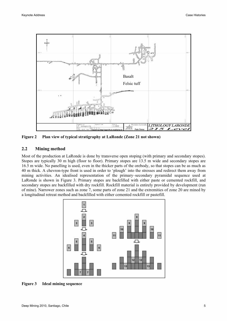
2.2 Mining method Most of the production at LaRonde is done by transverse open stoping (with primary and secondary stopes). Stopes are typically 30 m high (floor to floor). Primary stopes are 13.5 m wide and secondary stopes are 16.5 m wide. No panelling is used, even in the thicker parts of the orebody, so that stopes can be as much as 40 m thick. A chevron-type front is used in order to ‘plough’ into the stresses and redirect them away from mining activities. An idealised representation of the primary–secondary pyramidal sequence used at LaRonde is shown in Figure 3. Primary stopes are backfilled with either paste or cemented rockfill, and secondary stopes are backfilled with dry rockfill. Rockfill material is entirely provided by development (run of mine). Narrower zones such as zone 7, some parts of zone 21 and the extremities of zone 20 are mined by a longitudinal retreat method and backfilled with either cemented rockfill or pastefill.
1
2 8
3 3 9 9
10 10
4 11 11
5 5
6 6
12 12
13 13
7 7
Figure 3 Ideal mining sequence
Basalt
Felsic tuff

LaRonde Extension — mine design at three kilometres F. Mercier-Langevin
6 Deep Mining 2010, Santiago, Chile
2.3 Rock mass behaviour As the spacing of the foliation planes and the degree of sericitic alteration vary within the rock mass, its resulting behaviour can vary dramatically from one area of the mine to another. Some areas are characterised by tighter foliation and a higher degree of alteration, which results in large scale aseismic deformation in haulage drives developed at a shallow angle to foliation (Mercier-Langevin and Turcotte, 2007). Conversely, more competent areas (less prominent foliation and a low degree of alteration) display only minor closure, but can be hit by significant levels of seismicity (Mercier-Langevin and Hudyma, 2007).
The failure zone created by mining is quite extensive, as evidenced by the large distance between the seismicity front and actual stoping (Figure 4 – longitudinal view on left, section view on right). In well established mining horizons, the failure front created by the abutments can be traced as far as 30 m away from the actual mining front. This correlates well with field observations when mining primary and secondary stopes. Drilling in primary stopes is often difficult and the holes display various degrees of dog-earing, whereas drilling in secondary stopes is usually very easy and no sign of pressure is visible in the holes.
The extensive failure zones that develop over time around excavations result in unique challenges in all aspects of the operation. Some of the most significant that had to be introduced were in ground control strategies, as severe squeezing developed in haulage drives, pushing conventional support schemes to their limits and beyond.
Figure 4 Failure front as evidenced by seismicity (after Hudyma and Brummer, 2006)
3 Major challenges From the first few diamond drill holes that intersected the orebody below 2.5 km, the LaRonde Extension Project was rife with challenges that would require innovative thinking. Cost and timing issues were among the main concerns. Maintaining excavations operational and secure for their design life, which was already a challenge at LaRonde was also seen as a potential major issue. Finally, establishing adequate ventilation to sustain mining activities needed a great deal of reflection as well.
215 Level
155 Level
194 Level
215 Level
194 Level
Keynote Address Case Histories
Deep Mining 2010, Santiago, Chile 7
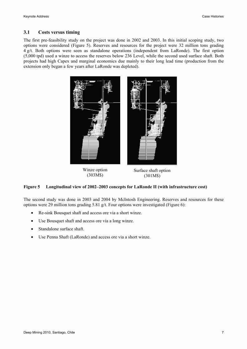
3.1 Costs versus timing The first pre-feasibility study on the project was done in 2002 and 2003. In this initial scoping study, two options were considered (Figure 5). Reserves and resources for the project were 32 million tons grading 4 g/t. Both options were seen as standalone operations (independent from LaRonde). The first option (5,000 tpd) used a winze to access the reserves below 236 Level, while the second used surface shaft. Both projects had high Capex and marginal economics due mainly to their long lead time (production from the extension only began a few years after LaRonde was depleted).
Winze option
(303M$)
Surface shaft option
(301M$)
Figure 5 Longitudinal view of 2002–2003 concepts for LaRonde II (with infrastructure cost)
The second study was done in 2003 and 2004 by McIntosh Engineering. Reserves and resources for these options were 29 million tons grading 5.81 g/t. Four options were investigated (Figure 6):
• Re-sink Bousquet shaft and access ore via a short winze.
• Use Bousquet shaft and access ore via a long winze.
• Standalone surface shaft.
• Use Penna Shaft (LaRonde) and access ore via a short winze.

LaRonde Extension — mine design at three kilometres F. Mercier-Langevin
8 Deep Mining 2010, Santiago, Chile
Bousquet and short winze
(307M$) Bousquet and long winze
(294M$) Surface shaft
(284M$) Penna and short winze
(274M$)
Figure 6 Longitudinal view of 2003–2004 concepts for LaRonde II (with infrastructure cost)
Again, all projects had high Capex and marginal economics due mainly to the fact that they were designed as standalone operations and synergies were minimal between LaRonde and the extension. The projects all resulted in a production stoppage between LaRonde and the Extension.
In 2005 and 2006, a last and final feasibility study was undertaken. Reserves were 18.8 million tons grading 6.03 g/t. The strategy used in this last iteration was to see LaRonde II as an extension of LaRonde rather than as a standalone operation. This would enable the mine to make maximum use of existing infrastructure and minimise construction time prior to shaft sinking. In practice, this was achieved by placing the winze as close as possible to the Penna Shaft and shortening the winze as much as possible. The vertical reach lost by shortening the shaft would be achieved via a long ramp (Figure 7). The project was renamed LaRonde Extension. It received the go ahead from the board of directors and construction began shortly thereafter.
Figure 7 Longitudinal view of 2006 concept for LaRonde Extension
Keynote Address Case Histories
Deep Mining 2010, Santiago, Chile 9
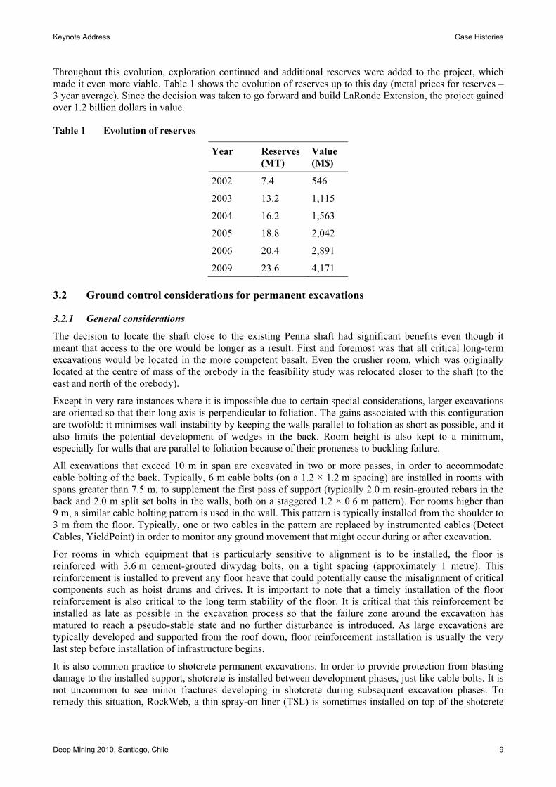
Throughout this evolution, exploration continued and additional reserves were added to the project, which made it even more viable. Table 1 shows the evolution of reserves up to this day (metal prices for reserves – 3 year average). Since the decision was taken to go forward and build LaRonde Extension, the project gained over 1.2 billion dollars in value.
Table 1 Evolution of reserves
Year Reserves (MT)
Value (M$)
2002 7.4 546
2003 13.2 1,115
2004 16.2 1,563
2005 18.8 2,042
2006 20.4 2,891
2009 23.6 4,171
3.2 Ground control considerations for permanent excavations
3.2.1 General considerations
The decision to locate the shaft close to the existing Penna shaft had significant benefits even though it meant that access to the ore would be longer as a result. First and foremost was that all critical long-term excavations would be located in the more competent basalt. Even the crusher room, which was originally located at the centre of mass of the orebody in the feasibility study was relocated closer to the shaft (to the east and north of the orebody).
Except in very rare instances where it is impossible due to certain special considerations, larger excavations are oriented so that their long axis is perpendicular to foliation. The gains associated with this configuration are twofold: it minimises wall instability by keeping the walls parallel to foliation as short as possible, and it also limits the potential development of wedges in the back. Room height is also kept to a minimum, especially for walls that are parallel to foliation because of their proneness to buckling failure.
All excavations that exceed 10 m in span are excavated in two or more passes, in order to accommodate cable bolting of the back. Typically, 6 m cable bolts (on a 1.2 × 1.2 m spacing) are installed in rooms with spans greater than 7.5 m, to supplement the first pass of support (typically 2.0 m resin-grouted rebars in the back and 2.0 m split set bolts in the walls, both on a staggered 1.2 × 0.6 m pattern). For rooms higher than 9 m, a similar cable bolting pattern is used in the wall. This pattern is typically installed from the shoulder to 3 m from the floor. Typically, one or two cables in the pattern are replaced by instrumented cables (Detect Cables, YieldPoint) in order to monitor any ground movement that might occur during or after excavation.
For rooms in which equipment that is particularly sensitive to alignment is to be installed, the floor is reinforced with 3.6 m cement-grouted diwydag bolts, on a tight spacing (approximately 1 metre). This reinforcement is installed to prevent any floor heave that could potentially cause the misalignment of critical components such as hoist drums and drives. It is important to note that a timely installation of the floor reinforcement is also critical to the long term stability of the floor. It is critical that this reinforcement be installed as late as possible in the excavation process so that the failure zone around the excavation has matured to reach a pseudo-stable state and no further disturbance is introduced. As large excavations are typically developed and supported from the roof down, floor reinforcement installation is usually the very last step before installation of infrastructure begins.
It is also common practice to shotcrete permanent excavations. In order to provide protection from blasting damage to the installed support, shotcrete is installed between development phases, just like cable bolts. It is not uncommon to see minor fractures developing in shotcrete during subsequent excavation phases. To remedy this situation, RockWeb, a thin spray-on liner (TSL) is sometimes installed on top of the shotcrete
LaRonde Extension — mine design at three kilometres F. Mercier-Langevin
10 Deep Mining 2010, Santiago, Chile
layer. This 4 mm polyurea membrane is capable of up to 100% elongation. It provides retainment for smaller pieces of shotcrete that might otherwise get dislodged by cracking and become potential hazards.
3.2.2 Case study – production hoist room
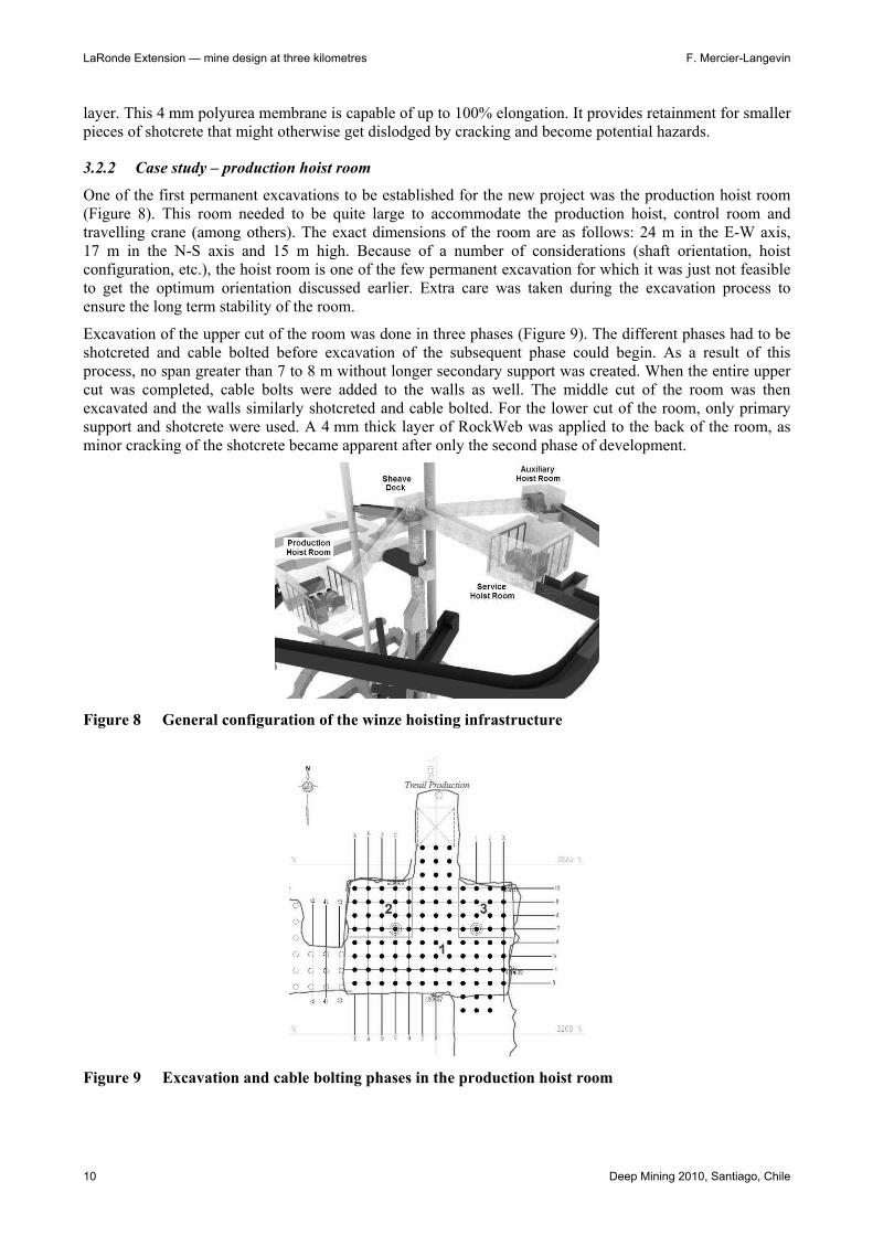
One of the first permanent excavations to be established for the new project was the production hoist room (Figure 8). This room needed to be quite large to accommodate the production hoist, control room and travelling crane (among others). The exact dimensions of the room are as follows: 24 m in the E-W axis, 17 m in the N-S axis and 15 m high. Because of a number of considerations (shaft orientation, hoist configuration, etc.), the hoist room is one of the few permanent excavation for which it was just not feasible to get the optimum orientation discussed earlier. Extra care was taken during the excavation process to ensure the long term stability of the room.
Excavation of the upper cut of the room was done in three phases (Figure 9). The different phases had to be shotcreted and cable bolted before excavation of the subsequent phase could begin. As a result of this process, no span greater than 7 to 8 m without longer secondary support was created. When the entire upper cut was completed, cable bolts were added to the walls as well. The middle cut of the room was then excavated and the walls similarly shotcreted and cable bolted. For the lower cut of the room, only primary support and shotcrete were used. A 4 mm thick layer of RockWeb was applied to the back of the room, as minor cracking of the shotcrete became apparent after only the second phase of development.
Figure 8 General configuration of the winze hoisting infrastructure
Figure 9 Excavation and cable bolting phases in the production hoist room

Keynote Address Case Histories
Deep Mining 2010, Santiago, Chile 11
As mentioned earlier, even millimetric floor heave is a major concern when dealing with sensitive equipment such as hoists. For this reason, it was decided that reinforcement of the floor of the room where the base of the hoist would be sitting was a necessary precaution. This reinforcement consisted of 3.6 m cement-grouted #7 diwydag bolts on a 1.2 × 1.2 m pattern. These bolts were installed at an 80 degree angle towards the north in order to intercept and lock in place foliation planes (dipping 80 degrees towards the south). Figure 10 shows the configuration of the reinforcement as well as the concrete foundation of the hoist. Similar excavation strategies will be used in the months to come for major infrastructure such as the 280 Level crusher and 278 garages.
Figure 10 Floor reinforcement in production hoist room
3.2.3 Stope sequencing and ore access
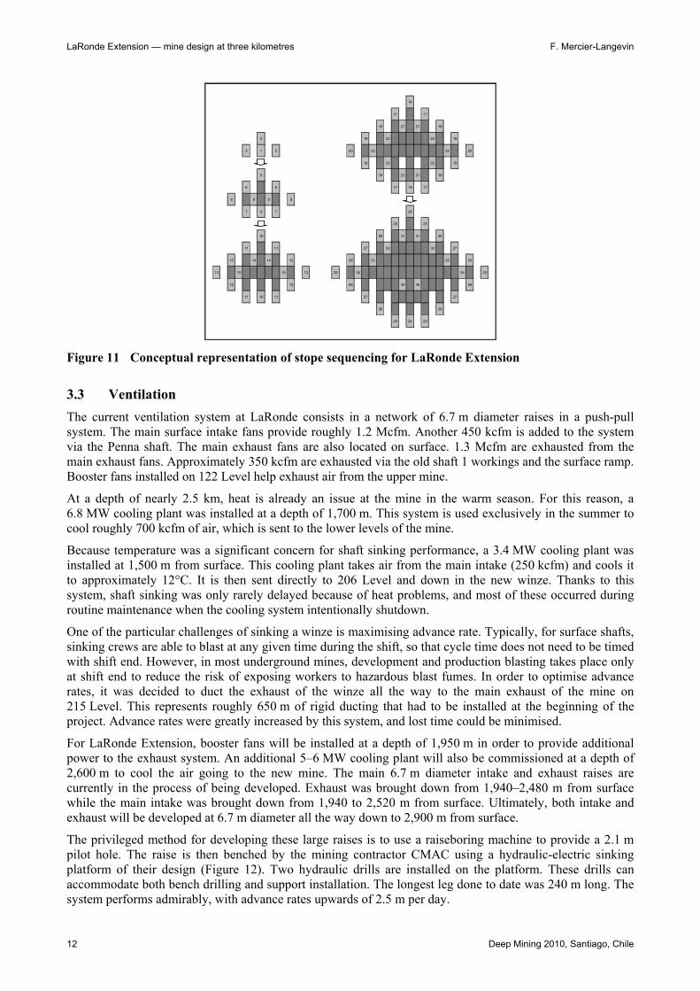
It is beyond the scope of this paper to go at length about the geomechanical specifics of stope sequencing at LaRonde (which were already discussed at length in other publications, Mercier-Langevin, 2008). However, it is relevant to note that the sequence planned for the extraction of LaRonde Extension will be slightly different than what is currently being used at LaRonde. The sequence is basically a primary-secondary pyramid coupled with an underhand primary-secondary pyramid. The end result is reminiscent of a diamond shape with four advancing primary stope fronts (Figure 11). It is important to note that in order to save on development through backfill, secondary stopes in the underhand front are actually mined in an overhand fashion once primaries have isolated a sufficiently high column of secondaries (typically 2 or 3 lifts).
LaRonde Extension — mine design at three kilometres F. Mercier-Langevin
12 Deep Mining 2010, Santiago, Chile
16
17 17
18 21 21 18
2 19 22 22 19
3 1 3 20 23 23 20
19 22 22 19
5 18 21 21 18
6 6 17 16 17
8 9 9 8
7 4 7 24
25 25
10 26 31 31 26
11 11 27 32 32 27
12 14 14 12 28 33 33 28
13 15 15 13 29 34 34 29
12 12 28 30 30 28
11 10 11 27 27
26 26
25 24 25
Figure 11 Conceptual representation of stope sequencing for LaRonde Extension
3.3 Ventilation The current ventilation system at LaRonde consists in a network of 6.7 m diameter raises in a push-pull system. The main surface intake fans provide roughly 1.2 Mcfm. Another 450 kcfm is added to the system via the Penna shaft. The main exhaust fans are also located on surface. 1.3 Mcfm are exhausted from the main exhaust fans. Approximately 350 kcfm are exhausted via the old shaft 1 workings and the surface ramp. Booster fans installed on 122 Level help exhaust air from the upper mine.
At a depth of nearly 2.5 km, heat is already an issue at the mine in the warm season. For this reason, a 6.8 MW cooling plant was installed at a depth of 1,700 m. This system is used exclusively in the summer to cool roughly 700 kcfm of air, which is sent to the lower levels of the mine.
Because temperature was a significant concern for shaft sinking performance, a 3.4 MW cooling plant was installed at 1,500 m from surface. This cooling plant takes air from the main intake (250 kcfm) and cools it to approximately 12°C. It is then sent directly to 206 Level and down in the new winze. Thanks to this system, shaft sinking was only rarely delayed because of heat problems, and most of these occurred during routine maintenance when the cooling system intentionally shutdown.
One of the particular challenges of sinking a winze is maximising advance rate. Typically, for surface shafts, sinking crews are able to blast at any given time during the shift, so that cycle time does not need to be timed with shift end. However, in most underground mines, development and production blasting takes place only at shift end to reduce the risk of exposing workers to hazardous blast fumes. In order to optimise advance rates, it was decided to duct the exhaust of the winze all the way to the main exhaust of the mine on 215 Level. This represents roughly 650 m of rigid ducting that had to be installed at the beginning of the project. Advance rates were greatly increased by this system, and lost time could be minimised.
For LaRonde Extension, booster fans will be installed at a depth of 1,950 m in order to provide additional power to the exhaust system. An additional 5–6 MW cooling plant will also be commissioned at a depth of 2,600 m to cool the air going to the new mine. The main 6.7 m diameter intake and exhaust raises are currently in the process of being developed. Exhaust was brought down from 1,940–2,480 m from surface while the main intake was brought down from 1,940 to 2,520 m from surface. Ultimately, both intake and exhaust will be developed at 6.7 m diameter all the way down to 2,900 m from surface.
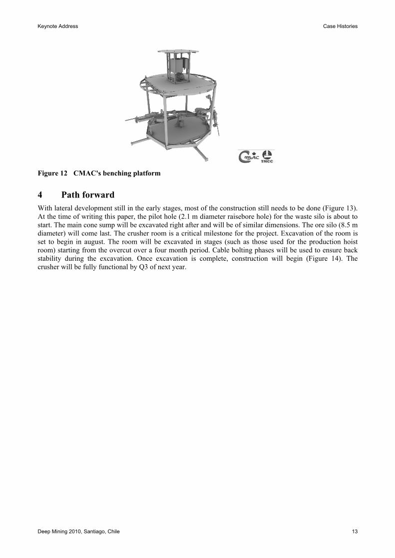
The privileged method for developing these large raises is to use a raiseboring machine to provide a 2.1 m pilot hole. The raise is then benched by the mining contractor CMAC using a hydraulic-electric sinking platform of their design (Figure 12). Two hydraulic drills are installed on the platform. These drills can accommodate both bench drilling and support installation. The longest leg done to date was 240 m long. The system performs admirably, with advance rates upwards of 2.5 m per day.
Keynote Address Case Histories
Deep Mining 2010, Santiago, Chile 13
Figure 12 CMAC's benching platform
4 Path forward With lateral development still in the early stages, most of the construction still needs to be done (Figure 13). At the time of writing this paper, the pilot hole (2.1 m diameter raisebore hole) for the waste silo is about to start. The main cone sump will be excavated right after and will be of similar dimensions. The ore silo (8.5 m diameter) will come last. The crusher room is a critical milestone for the project. Excavation of the room is set to begin in august. The room will be excavated in stages (such as those used for the production hoist room) starting from the overcut over a four month period. Cable bolting phases will be used to ensure back stability during the excavation. Once excavation is complete, construction will begin (Figure 14). The crusher will be fully functional by Q3 of next year.

LaRonde Extension — mine design at three kilometres F. Mercier-Langevin
14 Deep Mining 2010, Santiago, Chile
Figure 13 Layout of 278 and 282 Level
Figure 14 280 Level crusher
Development of ramps to reach the ore (which sits approximately 850 m to the southwest of the shaft) will be done in parallel with all this construction. For the first phase, a 750 m long coarse conveyor will be installed to bring the ore from the eastern part of the orebody (Level 290) to the crusher (Level 280, Figure 15). A second phase is planned whereby a 500 m long coarse conveyor will bring the ore from the western part of the orebody (Level 299) to the first coarse conveyor. Both conveyors will be developed at a
Waste silo (overcut)
Waste silo (undercut)
Ore silo (overcut)
Ore silo (undercut)
Pumping station
Cone sump
Main mechanical shop
Crusher room (overcut)
Crusher room (undercut)

Keynote Address Case Histories
Deep Mining 2010, Santiago, Chile 15
17% grade in order to lower the centre of mass of rock handling and minimise the need for trucking. For simplicity, only the west part of Level 299 and east part of Level 290 are shown. In reality, the two levels overlap each other almost completely.
Figure 15 Coarse conveyor phases 1 and 2
5 Conclusion LaRonde Mine has been Agnico-Eagle's flagship for a number of years now. The rapidly growing mining company has recently built five new mines (Goldex, Lapa and Meadowbank in Canada, Kittila in Finland and Pinos Altos in Mexico). However, with 4.1 million ounces, LaRonde Extension remains the most important project for the company in terms of reserves, which will ensure that the mine will keep its status for many years to come.
This paper provides a series of snapshots of what really is a massive undertaking. Building a new mine starting at a depth of 2 km poses unique challenges, some of which were discussed.
References Agnico-Eagle Mines Ltd (2010) Press Release: Agnico-Eagle reports fourth quarter and full year 2009 results; record
quarterly and annual revenue and gold production; record gold reserves and resources, February 17, 2010, www.agnico-eagle.com.
Hudyma, M. and Brummer, R.K. (2006) Mining induced seismicity review – 2006, Report to Agnico-Eagle Mines Ltd., Itasca Consulting Canada Inc., Canada.
Mercier-Langevin, F. (2008) Stope Performance Under Post-Peak Conditions, Strategic versus Tactical Approaches in Mining, Quebec City, Canada, pp. 240–250.
Mercier-Langevin, F. and Hudyma, M. (2007) The development and implementation of a comprehensive seismic risk management plan at Agnico-Eagle’s LaRonde Mine, in Proceedings of the Fourth International Seminar on Deep and High Stress Mining, Y. Potvin (ed), Australian Centre for Geomechanics, Perth, Australia, pp. 221–232.
Mercier-Langevin, F. and Turcotte, P. (2007) Evolution of ground support practices at Agnico Eagle’s LaRonde Division: innovative solutions to high stress yielding ground, in Proceedings 1st Canada–U.S. Rock Mechanics Symposium, Rock Mechanics: Meeting Society’s Challenges and Demands, E. Eberhardt, D. Stead, T. Morrison (eds), Taylor and Francis, London, pp. 1497–1504.

LaRonde Extension — mine design at three kilometres F. Mercier-Langevin
16 Deep Mining 2010, Santiago, Chile