LARIMER COUNTY RURAL AREA ROAD STANDARDS€¦ · LARIMER COUNTY RURAL AREA ROAD STANDARDS Larimer...
165
LARIMER COUNTY RURAL AREA ROAD STANDARDS Larimer County Engineering Department 200 West Oak Street, Suite 3000 PO Box 1190 Fort Collins, CO 80522 (970) 498-5700 Fax: (970) 498-7986 October 22, 2007
Transcript of LARIMER COUNTY RURAL AREA ROAD STANDARDS€¦ · LARIMER COUNTY RURAL AREA ROAD STANDARDS Larimer...

LARIMER COUNTY RURAL AREA ROAD STANDARDS
Larimer County Engineering Department 200 West Oak Street, Suite 3000
PO Box 1190 Fort Collins, CO 80522
(970) 498-5700 Fax: (970) 498-7986
October 22, 2007

Larimer County Rural Area Road Standards Page i October 22, 2007
LARIMER COUNTY RURAL AREA ROAD STANDARDS Table of Contents
CHAPTER 1 – GENERAL INFORMATION........................................................................................1-1 1.1 PURPOSE ............................................................................................................................................1-1 1.2 SCOPE ................................................................................................................................................1-1 1.3 AUTHORITY........................................................................................................................................1-1 1.4 APPLICABILITY ..................................................................................................................................1-1 1.5 AMENDMENT AND REVISIONS ............................................................................................................1-1 1.6 ENFORCEMENT RESPONSIBILITY ........................................................................................................1-2 1.7 REVIEW AND APPROVAL ....................................................................................................................1-2 1.8 INTERPRETATION ...............................................................................................................................1-2 1.9 RELATIONSHIPS TO OTHER STANDARDS ............................................................................................1-2 1.10 VARIANCES (DEPARTURES FROM THE STANDARDS) AND APPEALS..................................................1-3 1.11 AUTHORITY OF DIRECTOR OF PUBIC WORKS ...................................................................................1-3 1.12 FLOOD PLAIN ...................................................................................................................................1-3 1.13 COST ESTIMATE AND IMPROVEMENT AGREEMENT ..........................................................................1-3 1.14 THE PUBLIC ROAD SYSTEM .............................................................................................................1-4 1.15 NEW COUNTY ROADS ......................................................................................................................1-4
1.15.1 Planning Standards .................................................................................................................1-4 1.15.2 Design Standards ....................................................................................................................1-5 1.15.3 Construction and Testing Standards .......................................................................................1-5 1.15.4 Construction Warranty and Collateral....................................................................................1-5
CHAPTER 2 – SUBMITTAL PROCEDURES......................................................................................2-1 2.1 DRAWINGS AND SPECIFICATIONS SUBMITTAL PROCEDURE ...............................................................2-1
2.1.1 General......................................................................................................................................2-1 2.1.2 Pre-Application Conference......................................................................................................2-1 2.1.3 Preliminary Design and Final Design.......................................................................................2-1 2.1.4 Review and Approval Process ...................................................................................................2-1 2.1.5 Revisions or Updates to Approved Final Construction Plan.....................................................2-2
2.1.5.1 Submittal Requirements......................................................................................................................2-2 2.1.5.2 Minor and Major Revisions ................................................................................................................2-2
2.2 SUBMITTAL CHECKLIST .....................................................................................................................2-3 CHAPTER 3 – SUBMITTAL REQUIREMENTS FOR CONSTRUCTION PLANS........................3-1
3.1 GENERAL ...........................................................................................................................................3-1 3.2 PLAN SET ...........................................................................................................................................3-1
3.2.1 Professional Engineer Certification..........................................................................................3-1 3.2.2 Indemnification Statement .........................................................................................................3-1 3.2.3 Vicinity Map ..............................................................................................................................3-2 3.2.4 Key Map ....................................................................................................................................3-2
3.3 CONSTRUCTION PLANS AND DETAIL SHEETS .....................................................................................3-2 3.3.1 Title Block .................................................................................................................................3-2 3.3.2 Standard Signature Block..........................................................................................................3-2 3.3.3 Construction Benchmark Monumentation.................................................................................3-3 3.3.4 General Standard Notes for Final Construction Plans .............................................................3-3 3.3.5 Scale ..........................................................................................................................................3-3 3.3.6 North Arrow ..............................................................................................................................3-3 3.3.7 Date of Plan ..............................................................................................................................3-3 3.3.8 Index..........................................................................................................................................3-3 3.3.9 Legend of Symbols.....................................................................................................................3-3 3.3.10 Utilities ....................................................................................................................................3-3

Table of Contents
Larimer County Rural Area Road Standards Page ii October 22, 2007
3.3.11 Typical Street Sections ............................................................................................................3-3 3.3.12 Roadway Cross Sections..........................................................................................................3-4 3.3.13 Street Improvement Details .....................................................................................................3-4
3.4 REQUIREMENTS FOR ROAD PLAN AND PROFILE DRAWINGS...............................................................3-4 3.4.1 Plan View ..................................................................................................................................3-4 3.4.2 Profile........................................................................................................................................3-5
3.5 SIGNING AND STRIPING PLANS...........................................................................................................3-5 3.5.1 Signing Plan ..............................................................................................................................3-6 3.5.2 Striping Plan .............................................................................................................................3-6 3.5.3 Signing and Striping Plan Notes ...............................................................................................3-6 3.5.4 Signing and Pavement Marking Details ....................................................................................3-6 3.5.5 Construction Areas....................................................................................................................3-6
3.6 LANDSCAPE PLANS ............................................................................................................................3-6 CHAPTER 4 – ROAD DESIGN AND TECHNICAL CRITERIA.......................................................4-1
4.1 GENERAL ...........................................................................................................................................4-1 4.2 NEW ROADS .......................................................................................................................................4-1 4.3 ROAD DESIGN ....................................................................................................................................4-2
4.3.1 Classifications ...........................................................................................................................4-2 4.3.2 Alignment ..................................................................................................................................4-2
4.3.2.1 Horizontal Alignment .........................................................................................................................4-2 4.3.2.2 Vertical Alignment .............................................................................................................................4-3 4.3.2.3 Sight Distance.....................................................................................................................................4-4
4.3.3 Cross Slope................................................................................................................................4-4 4.3.3.1 Minimum Cross Slope ........................................................................................................................4-4 4.3.3.2 Maximum Allowable Cross Slope......................................................................................................4-4 4.3.3.3 Cross Slope for Road Modifications...................................................................................................4-4 4.3.3.4 Cross Slope for Cul-de-Sacs ...............................................................................................................4-4
4.3.4 Superelevation on Horizontal Curves........................................................................................4-4 4.3.5 Design Speed .............................................................................................................................4-5 4.3.6 Clear Zone.................................................................................................................................4-5 4.3.7 Roadscape Design and Right of Way Encroachment ................................................................4-5 4.3.8Roadside Safety ..........................................................................................................................4-5
4.4 ROAD SURFACING REQUIREMENTS ....................................................................................................4-5 4.4.1 Widening of Existing Paved Roadway.......................................................................................4-6
4.5 MEDIANS............................................................................................................................................4-6 4.6 NON-CONNECTIVE ROAD ALIGNMENTS .............................................................................................4-6
4.6.1 Construction Required as Part of Project .................................................................................4-6 4.6.2 Requirements for Future Road Projections...............................................................................4-6 4.6.3 Cul-De-Sacs ..............................................................................................................................4-7
4.7 DRAINAGE SYSTEMS ..........................................................................................................................4-7 4.7.1 Drainage....................................................................................................................................4-7 4.7.2 Subdrains...................................................................................................................................4-7 4.7.3 Rural Roadside Ditches.............................................................................................................4-7
4.7.3.1 Slope...................................................................................................................................................4-7 4.7.3.2 Maintenance .......................................................................................................................................4-7 4.7.3.3 Culvert Design....................................................................................................................................4-7
4.8 EMERGENCY ACCESS REQUIREMENTS ...............................................................................................4-8 4.8.1 Slope..........................................................................................................................................4-8 4.8.2 Cross Slope................................................................................................................................4-8 4.8.3 Lane Width ................................................................................................................................4-8 4.8.4 Vertical Clearance ....................................................................................................................4-8 4.8.5 Barricade...................................................................................................................................4-8 4.8.6 Roadway Surface.......................................................................................................................4-8
4.9 INTERSECTIONS ..................................................................................................................................4-8 4.9.1 Intersections Type and Design Criteria.....................................................................................4-8
4.9.1.1 Intersection Control Type ...................................................................................................................4-8 4.9.1.2 Location of Intersection......................................................................................................................4-9

Table of Contents
Larimer County Rural Area Road Standards Page iii October 22, 2007
4.9.1.3 Lane Alignment ..................................................................................................................................4-9 4.9.1.4 Angle of Intersection ..........................................................................................................................4-9 4.9.1.5 Horizontal Alignment and Vertical Profile .........................................................................................4-9 4.9.1.6 Auxiliary Lanes ..................................................................................................................................4-9 4.9.1.7 Design Vehicles................................................................................................................................4-10 4.9.1.8 Curb Returns.....................................................................................................................................4-10
4.10 ROAD NAME SIGNS AND TRAFFIC CONTROL DEVICES ...................................................................4-11 4.10.1 General..................................................................................................................................4-11 4.10.2 Traffic Signing.......................................................................................................................4-11
4.10.2.1 Type and Location of Signs ............................................................................................................4-11 4.10.2.2 New Roadway.................................................................................................................................4-11 4.10.2.3 Sign Posts, Supports, and Mountings..............................................................................................4-11 4.10.2.4 Sign Reflectivity .............................................................................................................................4-12 4.10.2.5 Panel Guage....................................................................................................................................4-12
4.10.3 Intersections ..........................................................................................................................4-12 4.10.3.1 Road Name Signs at Intersections ..................................................................................................4-12
CHAPTER 5 – GEOTECHNICAL STANDARDS AND PAVEMENT DESIGN ..............................5-1 5.1 SCOPE ................................................................................................................................................5-1 5.2 GENERAL ...........................................................................................................................................5-1 5.3 SOILS INVESTIGATION ........................................................................................................................5-1
5.3.1 Existing Pavement .....................................................................................................................5-1 5.3.2 Soils Investigation Report Content ............................................................................................5-1 5.3.3 Soil Samples ..............................................................................................................................5-2 5.3.4 Soil Grouping ............................................................................................................................5-2 5.3.5 Classification Testing ................................................................................................................5-2 5.3.6 Subgrade Support Testing .........................................................................................................5-3
5.3.6.1 Hveem Stabilometer ...........................................................................................................................5-3 5.3.6.2 Swell Tests..........................................................................................................................................5-3
5.3.7 Mitigation of Soils Problems .....................................................................................................5-3 5.4 PAVEMENT DESIGN STANDARDS........................................................................................................5-4
5.4.1 General Design Factors ............................................................................................................5-4 5.4.1.1 Minimum Thicknesses........................................................................................................................5-4
5.4.2 Special Considerations..............................................................................................................5-4 5.4.2.1 Staged Construction............................................................................................................................5-4 5.4.2.2 Full Depth Sections ............................................................................................................................5-4 5.4.2.3 Rehabilitating Existing Asphalt Roads ...............................................................................................5-4 5.4.2.4 Auxiliary Lanes ..................................................................................................................................5-4
5.5 FLEXIBLE PAVEMENT DESIGN............................................................................................................5-5 5.5.1 Definition...................................................................................................................................5-5 5.5.2 AASHTO Design Approach .......................................................................................................5-5
5.6 RIGID PAVEMENT DESIGN ..................................................................................................................5-7 5.6.1 Definition...................................................................................................................................5-7 5.6.2 AASHTO Design Approach .......................................................................................................5-8 5.6.3 Material Standards....................................................................................................................5-8
5.7 SUBGRADE INVESTIGATION AND PAVEMENT DESIGN REPORT ...........................................................5-9 CHAPTER 6 – STORMWATER MANAGEMENT .............................................................................6-1
6.1 GENERAL ...........................................................................................................................................6-1 6.2 CROSS FLOW DRAINAGE STRUCTURES ..............................................................................................6-1
CHAPTER 7 – BRIDGES AND MAJOR DRAINAGE STRUCTURES.............................................7-1 7.1 DESIGN STANDARDS ..........................................................................................................................7-1 7.2 IRRIGATION COMPANY APPROVAL.....................................................................................................7-1
7.2.1 General......................................................................................................................................7-1 7.2.2 Required Information ................................................................................................................7-1 7.2.3 Required Studies........................................................................................................................7-2 7.2.4 Final Plans and As-Built Drawings ..........................................................................................7-2

Table of Contents
Larimer County Rural Area Road Standards Page iv October 22, 2007
CHAPTER 8 – ENVIRONMENTAL AND AGRICULTURAL DESIGN GUIDELINES ................8-1 8.1 PRE-DESIGN STAGE ...........................................................................................................................8-1 8.2 DESIGN DOCUMENTS STAGE ..............................................................................................................8-2 8.3 PRELIMINARY REVIEW STAGE ...........................................................................................................8-3 8.4 FINAL DESIGN STAGE ........................................................................................................................8-3 8.5 CONSTRUCTION STAGE ......................................................................................................................8-3 8.6 PROJECT CLOSEOUT ...........................................................................................................................8-4
CHAPTER 9 – ROADWAY INSPECTION AND TESTING PROCEDURES ..................................9-1 9.1 GENERAL REQUIREMENTS .................................................................................................................9-1
9.1.1 Construction Requirements .......................................................................................................9-1 9.1.2 Developer Responsibility...........................................................................................................9-1 9.1.3 Definitions .................................................................................................................................9-2
9.1.3.1 Quality Control ...................................................................................................................................9-2 9.1.3.2 Quality Assurance...............................................................................................................................9-2
9.2 INSPECTIONS ......................................................................................................................................9-2 9.2.1 Larimer County .........................................................................................................................9-2 9.2.2 Developer ..................................................................................................................................9-2
9.3 TESTING..............................................................................................................................................9-3 9.4 WARRANTY PERIOD .............................................................................................................................9-3
CHAPTER 10 – ACCESS REQUIREMENTS AND CRITERIA ......................................................10-1 10.1 INTRODUCTION ..............................................................................................................................10-1
10.1.1 Authority................................................................................................................................10-1 10.1.2 Purpose..................................................................................................................................10-1 10.1.3 Implementation......................................................................................................................10-1
10.2 ADMINISTRATION...........................................................................................................................10-2 10.2.1 New Developments ................................................................................................................10-2
10.2.1.1 Land Division .................................................................................................................................10-2 10.2.1.2 Site Plan..........................................................................................................................................10-2 10.2.1.3 Interim Access ................................................................................................................................10-2
10.2.2 Existing Lots..........................................................................................................................10-3 10.2.3 Appeal Process ......................................................................................................................10-3 10.2.4 Illegal Access.........................................................................................................................10-3 10.2.5 Maintenance ..........................................................................................................................10-3 10.2.6 Change in Use of Access .......................................................................................................10-3 10.2.7 Non-Use of Access.................................................................................................................10-4
10.3 ACCESS CONTROL STANDARDS......................................................................................................10-4 10.3.1 Freeways and State Highways...............................................................................................10-4 10.3.2 Arterials.................................................................................................................................10-4
10.3.2.1 Spacing and Signalization Criteria..................................................................................................10-5 10.3.3 Major and Minor Collectors .................................................................................................10-5 10.3.4 Local Streets..........................................................................................................................10-5
10.4 ACCESS DESIGN STANDARDS AND SPECIFICATIONS.......................................................................10-6 10.4.1 Basic Criteria ........................................................................................................................10-6 10.4.2 Number of Accesses...............................................................................................................10-7 10.4.3 Minimum Spacing Between Accesses ....................................................................................10-6 10.4.4 Joint Entrances......................................................................................................................10-7 10.4.5 Entrance Angle......................................................................................................................10-7 10.4.6 Access Approaches ................................................................................................................10-7 10.4.7 Width of Access .....................................................................................................................10-7 10.4.8 Access Radii ..........................................................................................................................10-7 10.4.9 Access Surfacing....................................................................................................................10-8 10.4.10 Edge Clearance ...................................................................................................................10-8 10.4.11 Corner Clearance................................................................................................................10-8 10.4.12 Sight Distance......................................................................................................................10-8

Table of Contents
Larimer County Rural Area Road Standards Page v October 22, 2007
10.4.13 Speed Lane Changes ...........................................................................................................10-8 10.4.14 Access Profile and Slopes....................................................................................................10-9 10.4.15 Drainage..............................................................................................................................10-9 10.4.16 Gated Accesses ....................................................................................................................10-9
10.5 ACCESS PERMIT PROCESS FOR EXISTING LOTS ..............................................................................10-9 10.5.1 Obtaining A Permit ...............................................................................................................10-9 10.5.2 Construction of the Access ..................................................................................................10-10 10.5.3 Use of the Access.................................................................................................................10-11 10.5.4 Permit Fees .........................................................................................................................10-12
CHAPTER 11 – ACCESS AND UTILITY PERMIT APPLICATION REQUIREMENTS AND PROCEDURES........................................................................................................................................11-1
11.1 PURPOSE ........................................................................................................................................11-1 11.2 REQUIREMENTS..............................................................................................................................11-1 11.3 TYPES OF PERMITS .........................................................................................................................11-1
11.3.1 Right of Way Construction Permit.........................................................................................11-1 11.3.2 Access Permit ........................................................................................................................11-1
CHAPTER 12 – RIGHT OF WAY PERMITTING AND CONSTRUCTION STANDARDS FOR FACILITIES LOCATED IN PUBLIC RIGHT OF WAY...................................................................12-1
12.1 GENERAL .......................................................................................................................................12-1 12.1.1 Purpose..................................................................................................................................12-1 12.1.2 Introduction...........................................................................................................................12-1 12.1.3 Applicability ..........................................................................................................................12-1 12.1.4 Specific Conditions................................................................................................................12-1
12.1.4.1 Traffic Flow During Peak Hours ....................................................................................................12-1 12.1.4.2 End of Day Lane Conditions ..........................................................................................................12-2 12.1.4.3 Inspection Requests ........................................................................................................................12-2 12.1.4.4 Minimum Concrete Removals / Replacements..............................................................................12-2 12.1.4.5 Road Closures.................................................................................................................................12-2
12.1.5 Permit Fees ...........................................................................................................................12-2 12.1.6 Insurance Requirements ........................................................................................................12-2
12.2 PERMIT APPLICATION PROCESS .....................................................................................................12-2 12.2.1 Permit Forms.........................................................................................................................12-2 12.2.2 Submissions of Plans .............................................................................................................12-3
12.2.2.1 Required Plans................................................................................................................................12-3 12.2.2.2 Exceptions ......................................................................................................................................12-3 12.2.2.3 Supporting Documentation .............................................................................................................12-3
12.2.3 Submissions of Traffic Control Plans....................................................................................12-3 12.2.4 Other Permits ........................................................................................................................12-3
12.3 CONSTRUCTION DETAILS ...............................................................................................................12-3 12.3.1 General Conditions ...............................................................................................................12-3
12.3.1.1 Protection of Existing Improvements .............................................................................................12-4 12.3.1.2 Temporary Surfaces Required ........................................................................................................12-4 12.3.1.3 Pavement Patches ...........................................................................................................................12-4 12.3.1.4 Work to be Done in Expedient Manner ..........................................................................................12-4 12.3.1.5 Removal and Replacement of Unsatisfactory Work .......................................................................12-5 12.3.1.6 Tolerances.......................................................................................................................................12-5
12.3.2 Excavation.............................................................................................................................12-5 12.3.3 Blasting..................................................................................................................................12-6 12.3.4 Equipment..............................................................................................................................12-7 12.3.5 Dewatering ............................................................................................................................12-7 12.3.6 Removals ...............................................................................................................................12-7
12.3.6.1 Roads, Paved ..................................................................................................................................12-7 12.3.6.2 Roads, Gravel .................................................................................................................................12-7 12.3.6.3 Concrete Curb, Gutter and Sidewalk ..............................................................................................12-8
12.3.7 Backfill ..................................................................................................................................12-8 12.3.7.1 Flowable-Fill ..................................................................................................................................12-8

Table of Contents
Larimer County Rural Area Road Standards Page vi October 22, 2007
12.3.7.2 Conventional Backfill (Other than Flowable Fill) ..........................................................................12-8 12.3.7.3 Compaction Testing Requirements.................................................................................................12-9 12.3.7.4 Embankment and Slopes.................................................................................................................12-9
12.3.8 Restoration ............................................................................................................................12-9 12.3.8.1 Bore Holes – Vertical and Horizontal.............................................................................................12-9 12.3.8.2 Subgrade.........................................................................................................................................12-9 12.3.8.3 Asphalt Surfacing .........................................................................................................................12-10 12.3.8.4 Concrete Surfacing and Patching..................................................................................................12-11 12.3.8.5 Joint Filling...................................................................................................................................12-11
12.4 DEVELOPING A “QUALITY” APPROACH TO ROAD REPAIRS ..........................................................12-12 12.4.1 General................................................................................................................................12-12 12.4.2 Appearance..........................................................................................................................12-12 12.4.3 Rideability ...........................................................................................................................12-14 12.4.4 Pavement Management .......................................................................................................12-15 12.4.5 Future Maintenance ............................................................................................................12-17
12.5 TESTING........................................................................................................................................12-19 12.5.1 Description ..........................................................................................................................12-19 12.5.2 Testing Frequencies ............................................................................................................12-19
12.6 INSPECTION ..................................................................................................................................12-20 APPENDIX A – DEFINITIONS AND ABBREVIATIONS.................................................................A-1
A.1 GENERAL DEFINITIONS AND ABBREVIATIONS..................................................................................A-1 A.2 DEFINITION OF ROAD FUNCTIONAL CATEGORY ...............................................................................A-5 A.3 TERRAIN CLASSIFICATION ...............................................................................................................A-5
APPENDIX B – REFERENCES AND RESOURCE STANDARDS................................................... B-1 APPENDIX C – STANDARD DRAWINGS..........................................................................................C-1
DRAWING 1 RURAL ARTERIAL ROAD - TYPICAL SECTION DRAWING 2 RURAL MAJOR COLLECTOR ROAD - TYPICAL SECTION DRAWING 3 RURAL MINOR COLLECTOR ROAD - TYPICAL SECTION DRAWING 4 RURAL LOCAL ROAD - TYPICAL SECTION DRAWING 5 RURAL LOCAL LOW VOLUME ROAD - TYPICAL SECTION DRAWING 6 CUL – DE –SAC DETAIL DRAWING 7 TYPICAL ACCESS DETAIL DRAWING 8 STREET NAME SIGN MOUNTING AND LOCATION DETAIL DRAWING 9 LARIMER COUNTY STREET NAME SIGNS DETAIL DRAWING 10 GENERAL TRAFFIC SIGN LOCATION DETAIL DRAWING 11 CULVERT DETAIL
APPENDIX D – CONSTRUCTION STANDARDS .............................................................................D-1 D.1 ROADS..............................................................................................................................................D-1
D.1.1 Scope .......................................................................................................................................D-1 D.1.2 General....................................................................................................................................D-1 D.1.3 Regulations for Road Construction ........................................................................................D-1
D.2 REVISIONS TO CDOT STANDARDS SPECIFICATIONS FOR ROAD AND BRIDGE CONSTRUCTION ........D-3 D.2.1 Revision of Section 105 – Control of Work..............................................................................D-4 D.2.2 Revision of Section 106 – Control of Material ........................................................................D-6 D.2.3 Revision of Section 202 – Removal of Asphalt (Planing) ........................................................D-7 D.2.4 Revision of Section 203 – Excavation and Embankment .........................................................D-8 D.2.5 Revision of Section 206 – Excavation and Backfill for Structures ..........................................D-8 D.2.6 Revision of Section 217 – Herbicide Treatment ......................................................................D-8 D.2.7 Revision of Section 304 – Aggregate Base Course..................................................................D-9 D.2.8 Revision of Section 304 – Treated Aggregate Base Course ....................................................D-9 D.2.9 Revision of Section 308 – Fly Ash Treated Subgrade............................................................D-10 D.2.10 Revision of Section 401 – Plant Mix Pavements -General ..................................................D-13 D.2.11 Revision of Section 403 – Hot Mix Asphalt .........................................................................D-15 D.2.12 Revision of Section 412 – Portland Cement Concrete Pavement ........................................D-18

Table of Contents
Larimer County Rural Area Road Standards Page vii October 22, 2007
D.2.13 Revision of Section 601 – Structural Concrete....................................................................D-19 D.2.14 Revision of Section 609 – Curb and Gutter .........................................................................D-19 D.2.15 Revision of Section 629 – Survey Monumentation...............................................................D-20
APPENDIX E – CONSTRUCTION TESTING FREQUENCIES ...................................................... E-1 APPENDIX F – GUIDELINES FOR TRAFFIC IMPACT STUDIES ............................................... F-1
F.1 PURPOSE AND OVERVIEW ..................................................................................................................F-1 F.1.1 Types of Traffic Impact Studies................................................................................................ F-1 F.1.2 Responsibility and Qualifications ............................................................................................ F-1 F.1.3 Scoping..................................................................................................................................... F-1 F.1.4 Review by County..................................................................................................................... F-2
F.2 DEFINING A TRAFFIC IMPACT AREA ..................................................................................................F-2 F.3 LEVEL OF SERVICE, ACCESS, AUXILIARY LANE REQUIREMENTS, PASSENGER CAR EQUIVALENTS ...F-3 F.4 PAVING THRESHOLD STUDY ..............................................................................................................F-3
F.4.1 When a Paving Threshold Study is Required ........................................................................... F-3 F.4.2 Paving Threshold Study Requirements .................................................................................... F-3
F.5 INTERMEDIATE TRAFFIC IMPACT STUDY ...........................................................................................F-4 F.5.1 When an Intermediate Traffic Impact Study is Required ......................................................... F-4 F.5.2 Intermediate Traffic Impact Study Requirements..................................................................... F-4
F.6 WHEN A FULL TRAFFIC IMPACT STUDY IS REQUIRED .......................................................................F-5 F.6.1 When a Full Traffic Impact Study is Required......................................................................... F-5 F.6.2 Full Traffic Impact Study Requirements .................................................................................. F-5
F.7 ADDITIONAL REQUIREMENTS ............................................................................................................F-8 APPENDIX G – DESIGN AND CONSTRUCTION STANDARDS FOR PRIVATE LOCAL ACCESS ROADS......................................................................................................................................G-1
G.1 GENERAL .........................................................................................................................................G-1 G.1.1Purpose.....................................................................................................................................G-1 G.1.2 Administration .........................................................................................................................G-1
G.2 PRIVATE ROAD CONSTRUCTION PERMIT REQUIREMENTS ................................................................G-2 G.2.1 Multiple Access Roads.............................................................................................................G-2 G.2.2 Exception for Roads Built Before August 23, 1999 .................................................................G-2 G.2.3 Certification of Single Access Roads.......................................................................................G-2 G.2.4 Requirements for Application..................................................................................................G-2
G.3 ENGINEERED DESIGN .......................................................................................................................G-3 G.4 RESOLUTION OF CONFLICTS .............................................................................................................G-3 G.5 NOTICE OF COMPLETION ..................................................................................................................G-3 G.6 FEES .................................................................................................................................................G-4 G.7 ROAD DESIGN STANDARDS ..............................................................................................................G-4
G.7.1 Road Width ..............................................................................................................................G-4 G.7.1.1 Roads accessing multiple lots (Multiple access roads) .....................................................................G-4 G.7.1.2 Roads accessing single lots...............................................................................................................G-4 G.7.1.3 Clearance height ...............................................................................................................................G-4
G.7.2 Road Grade .............................................................................................................................G-5 G.7.3 Horizontal Road Curve............................................................................................................G-5 G.7.4 Vertical Road Curve ................................................................................................................G-5 G.7.5 Road Intersections ...................................................................................................................G-5 G.7.6 Dead End Roads ......................................................................................................................G-5 G.7.7 Cuts and Fills ..........................................................................................................................G-5
G.7.7.1 Cuts...................................................................................................................................................G-6 G.7.7.2 Fills ...................................................................................................................................................G-6 G.7.7.3 Slope Setbacks ..................................................................................................................................G-7
G.7.8 Drainage..................................................................................................................................G-7 G.7.9 Erosion Control and Site Reclamation ....................................................................................G-8 G.7.10 Buffer Zones for Streams, Intermittent Streams and Wetlands..............................................G-8 G.7.11 General Considerations.........................................................................................................G-9

Table of Contents
Larimer County Rural Area Road Standards Page viii October 22, 2007
G.7.12 Other Permits and Conditions...............................................................................................G-9 APPENDIX H – GENERAL NOTES.....................................................................................................H-1
H.1 PROFESSIONAL ENGINEER CERTIFICATION.......................................................................................H-1 H.2 INDEMNIFICATION STATEMENT........................................................................................................H-1 H.3 STANDARD SIGNATURE BLOCK........................................................................................................H-1 H.4 GENERAL STANDARD NOTES FOR CONSTRUCTION PLANS ...............................................................H-2
APPENDIX I – VARIANCE REQUEST SUBMITTAL FORM.......................................................... I-1

Larimer County Rural Area Road Standards Page 1-1 October 22, 2007
CHAPTER 1 – GENERAL INFORMATION
1.1 PURPOSE The purpose of this manual is to define policies and procedures, establish standards, develop a uniform interpretation of standards, and establish specific minimums as well as desirable standards for the planning, design, and construction of new roads and the improvement of existing roads in Larimer County.
The road standards contained in the main body of this manual apply to all road construction in Larimer County with the exception of Rural Land Use Plans (see Larimer County Land Use Code) and private local access roads (see Appendix G) constructed within subdivisions not governed by normal development review by the County. In addition, these standards do not apply to those areas located within a Town or City’s Growth Management Area where the County, through an IGA, has agreed to apply different standards.
1.2 SCOPE This manual is not a textbook or a substitute for engineering knowledge, experience, or judgment. It is intended to aid in deciding those factors needed to intelligently plan, design, construct, upgrade, and maintain land use development roads in the County.
The requirements contained in this manual apply to all new construction or other work done on, over, or under any land use development road, or other roads within the jurisdiction of the County that are planned for, subject to, or may become subject to public use.
Requirements of the manual may be enforced in the same manner as the Larimer County Land Use Code, including injunctions resulting in work stoppage or suit may be commenced for damages resulting to the roads or rights-of-way of the County due to noncompliance.
1.3 AUTHORITY This manual is authorized under Title 43, Article 2, Section 30-28-11 and Section 30-28-133 of the Colorado Revised Statutes, 1973, as amended.
1.4 APPLICABILITY This manual shall apply to all land within the unincorporated areas of the County except where superseded by other governmental jurisdiction.
1.5 AMENDMENT AND REVISIONS The standards may be amended as required. The Board of County Commissioners (BCC), following the recommendations of the County Engineer (Engineer) and Planning Commission, may consider revisions and/or amendments to this manual. The revisions will be adopted by resolution following a public hearing.

Chapter 1 – General Information Section 1.6 Enforcement Responsibility
Larimer County Rural Area Road Standards Page 1-2 October 22, 2007
1.6 ENFORCEMENT RESPONSIBILITY It shall be the duty of the Board of County Commissioners, acting through the Director of Public Works and the County Engineer, to enforce the provisions of this manual.
1.7 REVIEW AND APPROVAL The County will review all submittals for general compliance with these Roadway Standards. An approval by the County does not relieve the owner, owner’s engineer, or developer from final responsibility of insuring that the calculations, plans, specifications, construction, and as-built drawings are in compliance with this manual as stated in the owner’s engineer’s certification provided in accordance with Chapter 3.
1.8 INTERPRETATION In the interpretation and application of the provisions of this manual, the following shall govern:
A. In its interpretation and application, the provisions shall be regarded as the minimum requirements for the protection of the public health, safety, comfort, morals, convenience, prosperity, and welfare of the residents of the County.
B. Whenever a provision of this manual or any provision in any law, ordinance, resolution, rule, or regulation of any kind, contain any restrictions covering any of the same subject matter, whichever standards are more restrictive or impose higher standards or requirements shall govern.
C. The standards in this manual shall not modify or alter any road construction plans which have been filed with and accepted by the County prior to the effective date of this manual. This exception shall be subject to the conditions and limitations under which said plans were accepted by the Engineer.
D. Any ambiguities in the interpretation of material contained in this manual shall be resolved through the appeals process.
1.9 RELATIONSHIPS TO OTHER STANDARDS Since the County is the approval authority for land use changes, this manual, which stipulates certain minimum conditions for land use changes, shall apply. If special districts impose more stringent standards, this difference is not considered a conflict, the more stringent standard shall apply. If the State or Federal Government imposes more stringent standards, criteria, or requirements, these shall be incorporated into this document after the due process and public hearing(s) required to modify this manual.
The intent of this manual is to establish the minimum acceptable standard. In all cases, the highest possible engineering and construction standards should be used in the design of any road. Simply using a design standard presented in this manual will not guarantee the acceptance of a design by the Engineer and is therefore discouraged. This manual should be used for determining factors needed to plan, design, construct, maintain, and upgrade new roads and not as a substitute for knowledge, experience and sound judgment.

Chapter 1 – General Information Section 1.10 Variances (Departures from the Standards) and Appeals
Larimer County Rural Area Road Standards Page 1-3 October 22, 2007
1.10 VARIANCES (DEPARTURES FROM THE STANDARDS) AND APPEALS Variances from the standards in this manual will be considered on a case-by-case basis. If the special district, developer, contractor, or utility responsible to the County for public improvements desires to design and construct such improvements in variance to these standards, such variance(s) shall be identified in a written attachment to the initial submittal of construction plans. The variance request(s) shall consist of:
A. Identification of the standard provision to be waived or varied.
B. Identification of the alternative design or construction standards to be adhered to.
C. A thorough justification of the variance request including impact on capital and maintenance requirements and cost.
D. Request shall be prepared and sealed by a professional civil engineer licensed to practice in Colorado.
If, upon review and denial of the variance by the Engineer, the developer chooses to appeal the decision, they shall make his first appeal to the Director of Public Works (DPW).
If the denial of the variance is upheld by the DPW the developer may appeal to the Board of County Commissioner (BCC). The developer shall give the Director of Public Works at least five (5) working days notification prior to date of appeal to the BCC.
The developer shall make appeal to the BCC within 60 days from receipt of denial from the Director of Public Works. All notices, variances and appeals shall be in writing.
1.11 AUTHORITY OF DIRECTOR OF PUBIC WORKS The Director of Public Works or their designee shall have the authority, on behalf of the County, to ascertain that all design and construction is equal to or exceeds the minimum requirements set forth in these standards.
1.12 FLOOD PLAIN Portions of the County are within the Floodway, Flood Fringe and Flood Hazard overlay districts. The Larimer County Land Use Code and Stormwater Design Standards should be referred to for additional standards for roads within these districts.
1.13 COST ESTIMATE AND IMPROVEMENT AGREEMENT Any Applicant (i.e. the Land Subdivider) for Final Plat cost approval must provide the Engineering Department with an itemized estimate of all Public Improvements (as defined by State statute) associated with the subdivision. Cost estimates are to establish the amount of collateral provided by the applicant to secure the Development Agreement (DA). An amount equal to 15% of the total Cost Estimate shall be added to the total cost to cover construction contingencies.
After review and acceptance of the Cost Estimate by the Engineer, the cost estimate must be incorporated into a DA in a standard format or format suitable to the County Attorney. The DA should be executed by the applicant prior to the BCC hearing scheduled for the Final Plat approval. Collateral must be provided by the applicant in the form and amount as defined in the

Chapter 1 – General Information Section 1.14 The Public Road System
Larimer County Rural Area Road Standards Page 1-4 October 22, 2007
DA. If the DA conditions cannot be resolved at a staff level, the developer may appeal to the Director of Public Works and if conditions cannot be resolved the applicant may request a hearing before the BCC to further discuss and resolve any outstanding issues.
1.14 THE PUBLIC ROAD SYSTEM The Colorado Revised Statutes define public roads as all roads over private lands that have been dedicated to the public use by deed and accepted by the Board of County Commissioners, so long as no vacation of the road has occurred.
Public roads may or may not be maintained by the County. Larimer County maintains only those roads which the BCC, by written resolution, has agreed to maintain.
The State statutes have vested Larimer County with powers, if they so choose, to maintain, lay out, alter, add, delete, acquire property, and regulate traffic on the public roads under its jurisdiction.
1.15 NEW COUNTY ROADS New roads may be added to the County Road System by resolution passed by the Board of County Commissioners. Sources of new roads are additions, realignments, relinquished State Highways and Forest Service roads, subdivision and other development. Ordinarily, before a new road becomes a part of the County Road System, it passes through seven steps: planning, design, right-of-way acquisition or dedication, construction, inspection, warranty period, and possible acceptance through resolution.
The initial approval of subdivision road construction by the Engineer is for purposes of releasing the applicant’s Development Agreement collateral and not for purposes of acceptance by the County for maintenance. All roads proposed in any development shall be constructed to the required standard by the applicant with no liability or obligation for such construction or maintenance by the County.
1.15.1 Planning Standards Prior to the design of a new road, the functional classification and the design speed must be determined. The design speeds are addressed under Chapter 4.
If the developer's engineers have any questions in regard to the classification type of a particular road or roads within a proposed development, they should contact the Engineer for clarification.
Reserve strips or outlots controlling access to roads for other purposes shall not be permitted except where required by the County or the control of the reserve strip or outlot is placed in the County under conditions approved by the Board of County Commissioners.
Situations may arise in which both the County and city or town or other agency become involved in the review of a given development. The following procedure shall then apply:
1. Inter-Governmental Agreements. The conditions of the Inter-Governmental Agreements (IGAs) between the County and the incorporated area shall be complied with.

Chapter 1 – General Information Section 1.15 New County Roads
Larimer County Rural Area Road Standards Page 1-5 October 22, 2007
2. Review by Other Agencies. The County shall refer development plans to other involved agencies for review and comment. If the requirements of these other agencies are not in opposition to the County’s best interest, they shall be enforced by the County.
3. Utility Permits and Inspections. The other agencies shall be responsible for the issuance of utility permits and inspections of their respective utilities.
4. County Permits and Inspections. The County shall be responsible for the issuance of permits and inspections of all road construction and for installation or modification of utilities which occur within the rights-of-way of the County Road System. The County Engineering Department should be contacted for additional information.
1.15.2 Design Standards The design standards which have been established in this manual generally represent minimum values. The sources for these standards include applicable standards established by the American Association of State Highway and Transportation Officials (AASHTO) and by Colorado Department of Transportation (CDOT). Every effort has been made in this manual to provide consistent, accepted, and established standards to follow which will result in a safe and efficient road system at a reasonable cost to construct and maintain, while at the same time minimizing adverse environmental impacts.
In addition to the specific design standards found throughout other parts of this manual, the following general design principals shall be adhered to insofar as practicable:
1. Mountainous Terrain. In mountainous terrain, it may be preferable to provide more right-of-way than the minimum required to construct the road itself. The road will be permitted to wind around within the right-of-way to reduce cuts and unnecessary scarring, provided minimum standards are met. This higher standard right-of-way will permit improvements of the alignment as traffic warrants.
2. Existing Roads. Existing roads, including roads in subdivisions having preliminary plat approval in adjoining properties, shall be continued at equal or greater width and in similar alignments by roads proposed in the subdivision, unless variations are approved.
1.15.3 Construction and Testing Standards Specific construction specifications, both for materials and workmanship, and testing requirements, are found in Chapter 12 and Appendix D. The construction specifications used in work on the County Road System generally comply with the CDOT Standard Specifications for Road and Bridge Construction in effect at the time of construction.
1.15.4 Construction Warranty and Collateral The developer shall guarantee all portions of construction work done in the right-of-way for a period of two years after completion against defective workmanship and materials. The developer shall keep the roads and public improvements in good order and repair during the two-year period.

Chapter 1 – General Information Section 1.15 New County Roads
Larimer County Rural Area Road Standards Page 1-6 October 22, 2007
This warranty shall be secured in an amount and with a form of collateral acceptable to the County Attorney.
This warranty collateral shall be submitted concurrently with a request for release of the subdivision improvements collateral and the two-year warranty period shall commence on the date of said release of collateral. This warranty collateral will be held two years by Larimer County and will cover all improvements associated with the development.
Other types of improvements may combine their warranty collateral with the road warranty collateral if approved by the County Attorney.
During the course of the warranty period, periodic inspections will be conducted by the Engineer or their representative. If deficiencies are observed, other than normal deterioration, they shall be brought to the attention of the developer for his action.
The procedure for release of the warranty collateral shall be as established by the County Planning Department.

Larimer County Rural Area Road Standards Page 2-1 October 22, 2007
CHAPTER 2 – SUBMITTAL PROCEDURES
2.1 DRAWINGS AND SPECIFICATIONS SUBMITTAL PROCEDURE
2.1.1 General Consulting engineers and developers seeking approval and acceptance of civil engineering reports and construction plans shall follow the procedures outlined below. Submittal procedures and requirements for the various County land development processes can be found in Planning Department publications.
2.1.2 Pre-Application Conference The Planning Department routinely conducts pre-application conferences during which time applicants may ask questions about the various County land development processes, and obtain direction and/or information from the Planning and Engineering Departments. These meetings may be used by the applicant to obtain basic information about County procedures, practices or standards prior to beginning development planning.
2.1.3 Preliminary Design and Final Design The plan application submitted to the Planning Department for any land development, whether residential, commercial, or industrial shall include adequate detailed drawings for the entire street layout, storm drainage system (including Drainage and Erosion Control Reports), and grading. Approval of these plans, or their subsequent revisions, is required as a condition of scheduling the final plat for a hearing before the Board of County Commissioners (BCC).
County approval of engineering plans for public improvements prior to a BCC approval hearing requires:
1. Engineering Department review and approval of the final design and construction plans, drainage and erosion control plan and reports, and geotechnical reports.
2. Engineering Department approval of the public improvements cost estimate.
2.1.4 Review and Approval Process The Engineering Department review comments shall be submitted to the Larimer County Planning Department who shall forward the comments to the applicant. The Engineer may mark or redline the plans and return them to the consultant for revision. The redlined plans must be returned with the revised plans. When plans are returned to the consultant for lack of adequate information or are considered deficient, any resubmitted plans shall be considered a new submittal.
The review and approval process for Public Improvements Construction Plans shall also comply with the following criteria:
1. All Public Improvements Construction Plans shall be submitted directly to the Larimer County Planning Division who will distribute the plans for referral agency/department review.

Chapter 2 – Submittal Procedures Section 2.1 Drawings and Specifications Submittal Procedure
Larimer County Rural Area Road Standards Page 2-2 October 22, 2007
2. After the Consultant Engineer has addressed all review comments from each County Department, the Consultant Engineer shall re-submit through the Larimer County Planning Department.
3. Step 2 above, may be repeated until such time as the County deems the plans to be approvable. At that time, the Applicant will be contacted by the County with a request to submit signed and stamped mylar drawings for County signature. All approval blocks must be signed prior to the Engineering Department signing the plans.
4. Prior to the commencement of construction of public improvements within the Project, the Consultant Engineer (or Developer) shall return two (2) blue/blackline sets of the plans. The blue/blackline shall be copies of the originally signed and stamped plans.
2.1.5 Revisions or Updates to Approved Final Construction Plan
2.1.5.1 Submittal Requirements The following must accompany any revision or update to the approved final construction plans:
a. Scope of Changes. Construction plans, pavement design reports, drainage and erosion control reports, and other documents are approved initially for 24 months (2 years). If not constructed during this time period, they automatically become void and must be updated to meet current standards before any further permits can be issued.
b. Documentation of Changes. Whenever updates or revisions to previously approved construction plans, specifications, drainage and erosion reports, pavement design reports, or traffic impact studies are necessary, the owner’s engineer shall revise the originals and will submit updates or revisions through the normal document submittal process. A letter or transmittal sheet shall be provided which states the scope and reason for the construction plan revisions and identifies the revised drawings. Any resulting changes to other submittal documents that support the construction drawings must also be included. The previously approved construction plan sheets shall show the clouded revisions. Revisions shall be noted and stamped, signed and dated in boxes on the plans for that purpose.
2.1.5.2 Minor and Major Revisions Requests to revise the Public Improvements Construction Plans (the Plans) after the Local Entity has reviewed and approved the Plans shall be made in conformance with the following criteria:
a. Minor Revision 1) Shall be limited to minor revisions in roadway alignment, depth of
structural section, locations of curbs and gutters or sidewalks, relocation of traffic control devices, etc., which do not alter or impair the overall functional aspects of the improvements or work necessary to install the improvements.
2) May be administratively approved, at the discretion of the Engineer, by written confirmation. If the Engineer does not approve the Minor

Chapter 2 – Submittal Procedures Section 2.2 Submittal Checklist
Larimer County Rural Area Road Standards Page 2-3 October 22, 2007
Modification request, the Developer shall immediately comply with the plans or these Standards. The Engineer’s decision shall be the final decision regarding Minor Revisions unless appealed.
b. Major Revisions 1) Shall be a revision to the approved plans which is not specifically covered
under the provisions for Minor Revisions and which affects the functional aspects of the improvements or work to install the improvements.
2) The Major Modification cannot be administratively approved. The Developer is required to resubmit the Preliminary Plat or Preliminary Development Plan for review and subsequent approval by the Engineer, Planning Commission and/or Board of County Commissioners. Additionally, all work related to the Major Revision may not be allowed to continue until the County has approved the Major Revision or appeal.
2.2 SUBMITTAL CHECKLIST Submittals for land development improvements, special improvement districts, or other public improvements within Larimer County right-of-way must include all of the following, but not limited to:
A. Street plan and profile
B. Cross sections on 50 foot interval for required improvements to existing streets
C. Storm sewer plan and profile as recommended in the drainage report, including details for all structures and material specifications
D. Plan, profile, and construction details for structures and culverts
E. Storage volume-elevation-discharge information for stormwater detention ponds
F. Traffic signing and striping plan (as applicable)
G. Pavement design with supporting geotechnical report
H. Plan for traffic control during construction or any off site work within the County right-of-way
I. A typical section(s) showing pavement materials, thickness, width, and subgrade treatment as well as ditch depths and side slopes
J. Bridge structural design with supporting reports (if applicable)
K. Water and sanitary sewer construction plans as approved by the governing district or utility. If these plans represent lines for installation under existing or proposed County right-of-way, they must be approved by the County
L. Grading and overlot grading plan must show grades of all drainage facilities. For average lot sizes under one acre, the plan must show overlot grading with topographic contours before and after completion of grading. For average lot sizes greater than one acre, a typical lot grading detail for each lot shall be shown
M. Drainage report, erosion and sedimentation control plan (including storm water management plan (SWMP) and any other applicable permits)
N. Public improvements cost estimate

Chapter 2 – Submittal Procedures Section 2.2 Submittal Checklist
Larimer County Rural Area Road Standards Page 2-4 October 22, 2007
O. Final plat with appropriate dedication statements for public right-of-way and easements. Where a plat is not required, right-of-way easements must be submitted by separate document
P. Geotechnical engineering report with ground water and basement feasibility analysis and pavement design if needed
Q. Final Construction Plans for Utility Work in Larimer County Right-of-Way
R. Detailed general notes (see Appendix H)
S. Any necessary details needed for construction

Larimer County Rural Area Road Standards Page 3-1 October 22, 2007
CHAPTER 3 – SUBMITTAL REQUIREMENTS FOR CONSTRUCTION PLANS
3.1 GENERAL A. The following documentation is required in conjunction with the submittal of
construction plans for any roadway or storm drainage improvement for which approval by the Larimer County Engineering Department is required.
B. All construction plan submittals are required to comply with the provisions of this manual, the Larimer County Stormwater Design Standards, the Larimer County Land Use Code, and any other applicable standards.
C. Incomplete plan submittals will not be reviewed and will be returned to the Applicant.
D. All construction plans shall be on 24” x 36” sheets. All information shall be clear, concise and legible for final document acceptance. All sheets shall be uniform in contrast, scale, and proportionality to ensure readability. No text, symbols, hatching, and/or lines shall be placed on top of other such information to impair readability. An enlarged diagram or detail sheet shall be provided when the details cannot be clearly shown or read in the body of the plans. ,I�DQ�DUHD�LV�FRQJHVWHG�ZLWK�D�ORW�RI�GHWDLO��WKH�text information should be located in an open area and referenced back to the point of origin. Separate line weights shall be used.
3.2 PLAN SET The Plan set shall include, at a minimum, one cover sheet with general notes, construction notes, signature blocks, etc, improvement design sheet(s), and appropriate detail sheets.
3.2.1 Professional Engineer Certification All construction plans and drainage reports, soils reports, traffic studies, and pavement designs shall be prepared by, or under the direction of, a professional engineer, registered in the State of Colorado, and shall be reviewed for the minimum requirements set forth herein. The engineer should be aware that whenever unusual or serious problems are anticipated in conjunction with a proposed construction project, additional information and analysis beyond the minimum requirements of these specifications and criteria will be required.
All construction plan cover sheets shall bear the certification statement as shown in Appendix H and shall be signed and stamped by the Registered Professional Engineer who prepared or directed preparation of the construction plans.
All sheets shall include the Designer’s signature, stamp and date and shall be stamped and signed in accordance with the regulations established by the State of Colorado Board of Registration.
3.2.2 Indemnification Statement Larimer County shall not be responsible for the accuracy and adequacy of the design or dimensions and elevations on the plans. Larimer County, through the acceptance of the construction plan or drainage report, assumes no responsibility for the completeness and/or accuracy of the construction plan, drainage report, or submittal documents. All

Chapter 3 – Submittal Requirements for Construction Plans Section 3.3 Construction Plans and Detail Sheets
Larimer County Rural Area Road Standards Page 3-2 October 22, 2007
construction plan cover sheets shall bear the indemnification statement as shown in Appendix H.
3.2.3 Vicinity Map A vicinity map with a minimum scale of 1"=1000’ showing the location and name of all major county roadways within one mile of the proposed construction, and all other roadways in the vicinity of the proposed construction is required. The project area shall be indicated by shading. This map is required on the construction drawings cover sheet.
The vicinity map shall show all major county roadways and major drainage ways. The project Section, Township, and Range shall also be shown.
3.2.4 Key Map 1. A key map with a minimum scale of 1"=1000’ showing the location and name of
all roadways within and adjacent to the proposed construction and all future roadways is required.
A scale should be indicated. The key map should be oriented consistent with detail in the sheet, i.e. same north.
2. The key map is to appear on every sheet showing proposed roadway, storm drainage or grading improvements. The roadway or area that pertains to the design shall be shaded.
3.3 CONSTRUCTION PLANS AND DETAIL SHEETS All construction plans and detail sheets shall conform to the following criteria and show the following information. Additional specific requirements are discussed in other parts of these standards.
3.3.1 Title Block A title block is required on every sheet submitted for review and acceptance. The development name and filing number; the type of improvement; name, address, including zip code, and telephone number and name of the consulting engineer; name, address, including zip code, telephone number and name of the contact person at the developer; and sheet number (consecutive, beginning with the cover sheet) shall be included in the title block.
3.3.2 Standard Signature Block All roadway construction plans, storm sewer or other drainage improvement construction plans, and privately or publicly maintained stormwater detention facility construction plans must show the signature of the Engineer as shown in Appendix H. Construction plans that require approval from other reviewing agencies/entities may require additional signature blocks. This may include but not be limited to the Colorado Department of Transportation, fire district, water and/or sanitation district, and irrigation company, etc.

Chapter 3 – Submittal Requirements for Construction Plans Section 3.3 Construction Plans and Detail Sheets
Larimer County Rural Area Road Standards Page 3-3 October 22, 2007
3.3.3 Construction Benchmark Monumentation Two benchmarks shall be shown and described on the construction plans. The benchmarks need to be a marked cap that is stable, easily identifiable, and placed onsite in an area that will not likely be subject to disruption, removal, or replacement.
3.3.4 General Standard Notes for Final Construction Plans Larimer County has developed general standard notes that shall be included on all final construction plans. The required general standard notes for construction plans are shown in Appendix H.
3.3.5 Scale Scales listed are minimum. More detailed scales may be required where necessary to clearly show details.
1. Plan and profile plans: Horizontal 1"=50’, Vertical 1"=5’. 2. Master, preliminary, and final drainage plans; site plans, etc.: from 1"=50’ to
1"=100’.
3.3.6 North Arrow All design sheets shall have a north arrow oriented toward the top or right side of applicable sheets.
3.3.7 Date of Plan The original date of the plans and any subsequent revisions must be shown in the title block.
3.3.8 Index Each cover sheet shall include an index of all sheets within the Plan set.
3.3.9 Legend of Symbols Standard symbols shall be provided for all appurtenances related to each type of facility.
3.3.10 Utilities The type, size, location and number of all underground utilities shall be shown in the construction plans. Field verified elevations and locations may be required on the construction plans for all underground utilities which will potentially affect the design or construction. It will be the responsibility of the contractor to verify the existence and location of all underground utilities along their route of work prior to commencing any new construction. Field located utilities not shown on accepted construction plans shall be added to the record drawings.
3.3.11 Typical Street Sections Typical roadway cross sections for all roadways, existing or proposed, within and adjacent to the proposed development shall be shown on the construction drawings. They shall indicate the type of roadway(s), profile grade design point (centerline, flow-line, top of curb, lip of gutter, etc.), roadway width, lane width, right-of-way, type of curb, gutter and walk, pavement cross slope, pavement thickness, and structural material

Chapter 3 – Submittal Requirements for Construction Plans Section 3.4 Requirements for Road Plan and Profile Drawings
Larimer County Rural Area Road Standards Page 3-4 October 22, 2007
components of the pavement, base and subbase, together with specifications for treatment of subgrade and method of installation of pavement structure.
3.3.12 Roadway Cross Sections Cross-sections shall be required on any off site improvements and any other roadways as deemed necessary by the Engineer. The cross-sections shall indicate the profile grade design point (centerline, flow-line, top of curb, lip of gutter, etc.), roadway width, right-of-way, pavement cross slope, pavement and sub grade thickness, and tie in of proposed improvements with existing ground.
Roadway cross-sections shall be provided at intervals deemed necessary by the Engineer to effectively evaluate connection with the existing facilities, (typically every 50 feet horizontally). Addition road way cross sections will be required at driveways and intersections.
3.3.13 Street Improvement Details All pertinent details related to street improvements shall be shown on a detail sheet(s) for the project.
3.4 REQUIREMENTS FOR ROAD PLAN AND PROFILE DRAWINGS In addition to the requirements set forth elsewhere in these standards, the following information shall be shown on all roadway plans submitted for review and approval.
3.4.1 Plan View The plan view shall include, but not be limited to, the following:
1. Existing and proposed property and/or R.O.W. lines, easements and/or tracts. The type and dimension of the easement or tract is to be clearly labeled. Property lines and R.O.W. lines are to be dimensioned.
2. Survey lines and stations shall normally be based on centerline of street or flowline; other profiles may be included but shall be referenced to centerline stationing or flowline. Stationing is to be equated to flowline or edge of pavement stationing at cul-de-sacs.
3. Stationing should read in ascending order in the direction of the north arrow or to the right.
4. Roadways and roadway names. 5. Existing utilities and structures(showing as phantom lines), including, but not
limited to storm sewer, fence lines & gates, water lines, ditches or swales, electric lines, curbs and gutters, sewer lines, pavement limits, telephone lines, bridges or culverts, CATV lines, guardrails, signs, gas lines, and fiber optic lines, etc.
6. Station and critical elevation (flowline, invert of pipe, etc.) of all existing and proposed utility or drainage structures. Location of utilities shall be dimensioned horizontally from stationing with elevation.
7. Storm drainage flow direction arrows, particularly at intersections and all high and low points.
8. Match lines and consecutive sheet numbers, beginning with cover sheet.

Chapter 3 – Submittal Requirements for Construction Plans Section 3.5 Signing and Striping Plans
Larimer County Rural Area Road Standards Page 3-5 October 22, 2007
9. Station and elevation of all horizontal curves including PI, PC’s, PT’s, etc.; high or low point and PI of all vertical curves; existing and proposed, centerline bearings, distances, and complete curve data.
10. Curb return radii, existing and proposed. Stations and elevations of all curb returns; mid point elevations, flowline-flowline intersection elevations, and percent of grade from the P.C.R. to flowline-flowline intersections of all crosspans.
11. Centerline stations of all driveways and all intersecting roadways. 12. Survey tie lines to section corners or quarter corners, consistent with that shown
on the plat. 13. Intersections: Any roadway intersections shall include construction and lane
details for the new construction and existing facilities for a minimum of 150 feet beyond the limits of construction.
14. Basis of plan view and profile elevations shall be the same, i.e. flowline and flowline, top of curb and top of curb, etc.
15. Cul-de-sacs: High point and grades shown with percent arrows at critical points (cross-slope and flow line).
3.4.2 Profile The profile shall include, but not be limited to, the following:
1. Original ground (dashed) and design grade (heavy, solid). Both grades are to be plainly labeled and clearly distinguishable.
2. All design elevations shall be centerline. In some cases, additional vertical data may be required at intersections on curves, and in swales.
3. Stationing shall be continuous for the entire portion of the roadway shown in the plan view, with the centerline station of all driveways and all intersecting roadways clearly labeled.
4. All existing flow lines and pavement adjacent to the proposed design. The existing profile grades shall be measured by survey. Previously approved designs of Record Drawings are not an acceptable means of establishing existing grades.
5. Existing and new utilities. Elevation and location of all utilities in the immediate vicinity of the construction shall be shown on the plan and profile.
6. Station and elevation of all vertical grade breaks. 7. Distance and grade between VPI’s. 8. Vertical curves, with VPI, VPC, and VPT, high or low point stations and
elevations. All vertical curves shall be labeled with L, K, A.
3.5 SIGNING AND STRIPING PLANS All road improvement and/or, land development projects must incorporate a separate signage and striping plan in accordance with the criteria of this section. Striping plans are not typically required for local subdivision roads. However, sign plans are still required for all subdivisions.
All signing and striping plans shall conform to the most current edition of the Manual on Uniform Traffic Control Devices. All traffic control devices shall be fabricated and installed in accordance

Chapter 3 – Submittal Requirements for Construction Plans Section 3.6 Landscape Plans
Larimer County Rural Area Road Standards Page 3-6 October 22, 2007
with the Manual on Uniform Traffic Control Devices and Colorado Department of Transportation M and S Standards. Permanent signage and striping shall be complete and in place before any new roadway is opened to the public.
3.5.1 Signing Plan The permanent signing plan should:
1. Show the general longitudinal location of each sign (horizontal offset and station). 2. Specify the sign legend and sign type. 3. Specify the sign size. 4. Show Street Name Sign Mounting Detail, Larimer County Street Name Signs
Detail, and the General Traffic Sign Location Detail, as shown in Standard Drawings 8 & 9.
3.5.2 Striping Plan The striping plan must show:
1. Stripe color and type 2. Lane width, taper lengths, storage lengths, etc. 3. Striping/skip interval 4. All pavement marking materials, except point location markings, must meet
current CDOT specifications for water base traffic marking paint unless another material is specified by the engineer. All point location markings (stop bars, turn arrows, words, symbols, etc) must be 0.125 mil pre-formed thermo plastic.
5. Station and offset or dimensions to all angle points, symbol locations, and line terminations
6. Stripe dimensions 7. Raised median islands shall be delineated
3.5.3 Signing and Striping Plan Notes The signage and striping plan notes as shown in Appendix H shall be on all signage, striping plans and/or on the general notes sheet.
3.5.4 Signing and Pavement Marking Details The Larimer County signage details in this document shall be included in all sets of construction plans as applicable. The pavement marking details shall be the CDOT M&S Standards for pavement markings
3.5.5 Construction Areas A separate construction traffic control plan and construction phasing plan where applicable shall be included.
3.6 LANDSCAPE PLANS Outside of the Growth Management Areas, landscaping shall not be allowed within any existing or proposed right of way unless approved by the Engineer and shall not obstruct sight distance as defined in Chapter 4.

Larimer County Rural Area Road Standards Page 4-1 October 22, 2007
CHAPTER 4 – ROAD DESIGN AND TECHNICAL CRITERIA
4.1 GENERAL The provisions stipulated in this section are general in nature and shall be considered as applicable to all parts of these specifications, including any supplements and revisions. All construction within the public right-of-way shall be designed by or under the direct supervision of a registered professional engineer, licensed to practice in the State of Colorado. All drawings and support data submitted to the County for approval must bear the engineer’s seal and signature.
A. The design criteria, as presented, are intended to aid in preparation of plans and specifications, and include minimum standards where applicable.
B. These design criteria are considered minimum and a complete design will usually require more than is presented in this document.
C. As with any design criteria, occasions may arise where the minimum standards are either inappropriate or cannot be justified economically. In these cases a variance to these criteria shall be considered. Written request for each variance shall be directed to the Engineer and shall conform to criteria in "Variance Requests" found in Chapter 1. Design of all roads shall conform to this document, the County’s Transportation Plan (TP), any and all applicable County planning documents, CDOT Roadway Design Manual (latest edition), Standard Plans M & S Standards (latest edition), the Manual on Uniform Traffic Control Devices (MUTCD), and AASHTO A Policy on Geometric Design of Highways and Streets (latest edition).
D. This chapter defines layout criteria and other design criteria that shall be followed for locating and designing all roads located in unincorporated Larimer County identified in the Larimer County Land Use Code except those areas located within a Town or City’s Growth Management Area where the County, through an IGA, has agreed to apply different standards.
E. The standards and requirements contained in this manual and chapter only apply to rural, unincorporated areas, and areas outside of County acknowledged Growth Management Areas. Proposed “urban” level developments and improvements in these areas are not covered by this manual and are not allowed unless approved in writing by the Engineer. If approved by the Engineer, the proposed “urban” level improvements must at a minimum conform to the requirements of this manual as well as the applicable sections of the Larimer County Urban Area Street Standards (LCUASS). In these instances, the Engineer will determine which requirements of the LCUASS apply. Examples of “urban” level improvements include, but are not limited to: curb and gutter, sidewalks, pedestrian ramps, stormdrain inlets, sidewalk chases, crosspans, medians, traffic signals, etc.
4.2 NEW ROADS The TP shall be used for establishing approximate locations of Major roads. The Engineer shall hold approval authority for specific locations, retain the authority to designate collector roads, and retain authority for approval of the overall road layout.
All roads shall have a logical relationship to the existing topography and to the location of existing or platted roads within adjacent properties.

Chapter 4 – Road Design and Technical Criteria Section 4.3 Road Design
Larimer County Rural Area Road Standards Page 4-2 October 22, 2007
4.3 ROAD DESIGN
4.3.1 Classifications All roads are classified as Arterial, Collector or Local roads. These classifications relate to the function of the roads. Lower order roads function primarily as access to individual lots, and higher order roads function primarily for the purpose of mobility (expeditious movement of people and goods). Larimer County has adopted an expanded classifications system that is to be used within the County except for areas within recognized GMA’s in which case the County may, at its discretion apply the City or Town’s functional classification of roadways.
4.3.2 Alignment Horizontal and vertical road alignments should conform to existing land layout plus the following criteria:
4.3.2.1 Horizontal Alignment On Arterial and Major Collector roadways, curve radii and tangents shall be as large as possible using the minimums only where necessary. Angle point direction changes are not allowed. All changes in direction shall be made using standard curves.
a. Horizontal Curve Radii. The minimum allowable centerline radii for horizontal curves shall be as designated in Table 4-1. Reverse and compound curves should be used only when a single radius curve will not work. For driver safety, compound curves shall have a ratio no greater than 1.5 where the value of the larger radius is divided by the smaller radius.
b. Minimum Tangent Length. Requirements are as follows: 1) Intersection. Whenever a minor road intersects a road of higher
classification, a tangent length (measured from the nearest edge of pavement of the intersected road to the point of curvature in the intersecting road) shall be provided for a safe sight distance and safe traffic operation. The minimum required tangent lengths indicated in Table 4-1 apply to the minor leg(s) only. The angle of departure shall not exceed 10 degrees for the length of tangent.
2) Reverse Curves. The tangent between reverse curves shall be no less than the length shown in Table 4-1.
3) Broken Back Curves. Two curves in the same direction (broken back curves) shall be separated by a tangent with a length of at least 2 times the minimum length shown in Table 4-1.
c. Curves with Small Deflection Angles (10° or less). To reduce the appearance of kinks in the road, minimum lengths of curve shall be designed with minimum centerline arc lengths as shown in Table 4-1.
d. Horizontal Curves on Vertical Curves. For driver safety, horizontal curves shall not begin near the top of a crest vertical curve nor near the bottom of a sag vertical curve.

Chapter 4 – Road Design and Technical Criteria Section 4.3 Road Design
Larimer County Rural Area Road Standards Page 4-3 October 22, 2007
Table 4-1 Road Standards – Technical Design Criteria
Collector Design Element Arterial Major Minor Local Roads Design Speed Posted Speed
50 - 60 45 - 55
45 - 60 40 - 55
35 - 50 35 - 45
25 25
Minimum centerline radius (with no super-elevation)
NA 1039’-NA 510’-NA 165’
Maximum super-elevation 0.08 ft/ft 0.08 ft/ft 0.08 ft/ft NA Minimum tangent between curves or at intersections
400’ 400’ 200’ 100’
Minimum Centerline arc lengths
400’ 300’ 300’ 100’
Max Centerline Grade flat/rolling Mountains
8% 10%
8% 10%
8% 10%
8% 10%
Minimum Centerline Grade
0.5% 0.5% 0.5% 0.5%
Crest 84-151* 61-151 29-84 12 Minimum K-values for Vertical Curves*
Sag 96-136 79-136 49-96 26
Right of Way (ROW) Width 120’ 100’ 80’ 70’
* Range varies based on design speed.
e. Off-Site Design Centerline, Flowlines and Cross Sections. To assure that future road improvements will meet these Standards the design of the centerline, flowline, and cross sections of all roads, except cul-de-sacs, shall be continued for 500 feet beyond the proposed construction. The grade and ground lines of all Arterials shall be continued for a total of 1000 feet beyond the end of the proposed construction.
f. Overlay Areas. At a minimum, areas that will be overlayed must be designed to show at least a typical cross section for the area to be overlayed; a plan view with notes depicting areas that need: a leveling course, taper milling, patching, fabric, etc.; and notes about accesses and shouldering. Additional information may be required by the Engineer depending on the situation.
4.3.2.2 Vertical Alignment a. Maximum and Minimum Grades for Roads. The maximum and minimum
grades for specific road classifications are shown in to Table 4-1. b. Grade Breaks. No single point grade break shall exceed 0.50 percent. c. Requirements for Using Vertical Curves. Vertical curves are required for
grade changes that exceed 0.50 percent. A series of grade breaks may be used in lieu of a specified vertical curve as long as the series of breaks meet the vertical curve criteria in these Standards for the design speed. K-values for design shall conform to Table 4-1.

Chapter 4 – Road Design and Technical Criteria Section 4.3 Road Design
Larimer County Rural Area Road Standards Page 4-4 October 22, 2007
d. Vertical Clearance. Vertical clearance above a roadway is a minimum of 13.5 feet.
e. Off-Site Continuance of Grade and Ground Lines. To assure that future road improvements will meet these Standards the grade and ground lines of all local and collector roads, except cul-de-sacs, shall be continued for 500 feet beyond the proposed construction. The grade and ground lines of all Arterials shall be continued 1000 feet beyond the end of the proposed construction.
4.3.2.3 Sight Distance Sight distance requirements shall meet Section Four of the State of Colorado State Highway Access Code (most recent version).
4.3.3 Cross Slope Cross slope on a pavement is provided to drain water from the road surface. The design of cross slope shall consider driver comfort and safety.
4.3.3.1 Minimum Cross Slope A minimum cross slope on all new roads shall be 2.0 percent. Minimum cross slope on reconstruction or overlays is 1.5 percent.
4.3.3.2 Maximum Allowable Cross Slope Maximum allowable cross slope on all new construction shall be 3 percent. Maximum allowable Cross Slope on any reconstruction or overlays of existing roadways shall be 4 percent.
4.3.3.3 Cross Slope for Road Modifications When widening an existing road or adding turn lanes to an existing road, the resulting cross slope of the widened portion shall be within the limits stated above and the new cross slope shall be no less than the existing cross slope.
However, if the cross slope of the existing road exceeds 4 percent the cross slope shall be made acceptable by:
a. Leveling and overlaying with HMA b. Milling the existing asphalt to an acceptable cross slope and overlaying with
HMA c. Removing the existing asphalt, and reconstructing the roadway to meet the
standards.
4.3.3.4 Cross Slope for Cul-de-Sacs Refer to Standard Drawing 6 for cul-de-sac bulb cross slopes.
4.3.4 Superelevation on Horizontal Curves The purpose of superelevating a roadway is to improve the riding comfort on curves where the traveling speed is great enough to develop excess centrifugal force that is not counteracted by friction between the roadway and the tires of a vehicle. It is also used to maintain the riding comfort on smaller than standard curves.
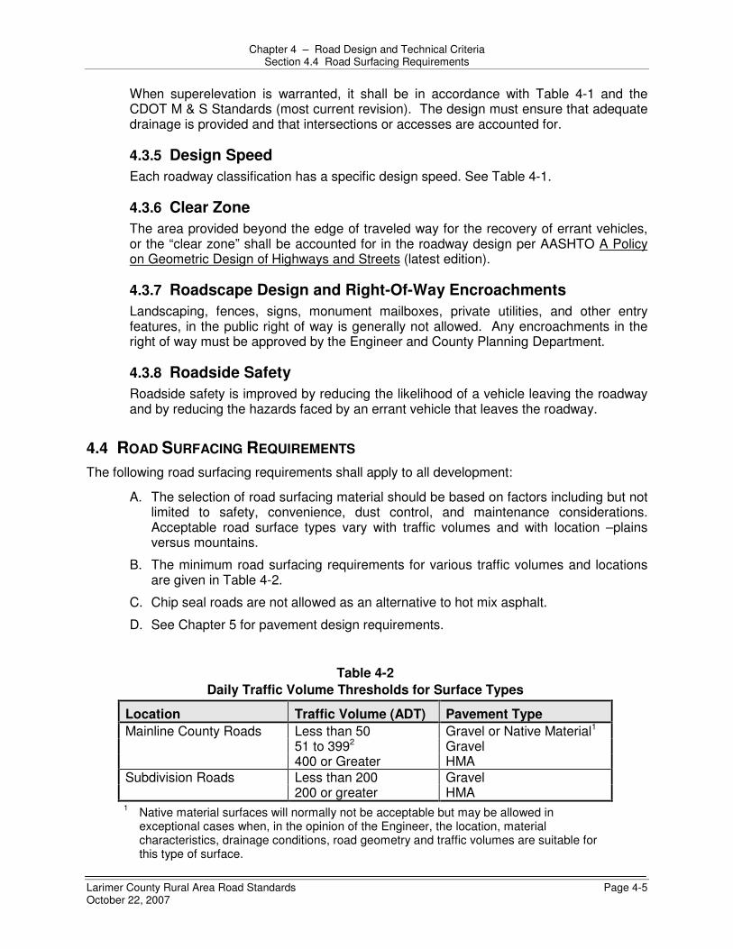
Chapter 4 – Road Design and Technical Criteria Section 4.4 Road Surfacing Requirements
Larimer County Rural Area Road Standards Page 4-5 October 22, 2007
When superelevation is warranted, it shall be in accordance with Table 4-1 and the CDOT M & S Standards (most current revision). The design must ensure that adequate drainage is provided and that intersections or accesses are accounted for.
4.3.5 Design Speed Each roadway classification has a specific design speed. See Table 4-1.
4.3.6 Clear Zone The area provided beyond the edge of traveled way for the recovery of errant vehicles, or the “clear zone” shall be accounted for in the roadway design per AASHTO A Policy on Geometric Design of Highways and Streets (latest edition).
4.3.7 Roadscape Design and Right-Of-Way Encroachments Landscaping, fences, signs, monument mailboxes, private utilities, and other entry features, in the public right of way is generally not allowed. Any encroachments in the right of way must be approved by the Engineer and County Planning Department.
4.3.8 Roadside Safety Roadside safety is improved by reducing the likelihood of a vehicle leaving the roadway and by reducing the hazards faced by an errant vehicle that leaves the roadway.
4.4 ROAD SURFACING REQUIREMENTS The following road surfacing requirements shall apply to all development:
A. The selection of road surfacing material should be based on factors including but not limited to safety, convenience, dust control, and maintenance considerations. Acceptable road surface types vary with traffic volumes and with location –plains versus mountains.
B. The minimum road surfacing requirements for various traffic volumes and locations are given in Table 4-2.
C. Chip seal roads are not allowed as an alternative to hot mix asphalt.
D. See Chapter 5 for pavement design requirements.
Table 4-2 Daily Traffic Volume Thresholds for Surface Types
Location Traffic Volume (ADT) Pavement Type Mainline County Roads Less than 50 Gravel or Native Material1 51 to 3992 Gravel 400 or Greater HMA Subdivision Roads Less than 200 Gravel 200 or greater HMA 1 Native material surfaces will normally not be acceptable but may be allowed in
exceptional cases when, in the opinion of the Engineer, the location, material characteristics, drainage conditions, road geometry and traffic volumes are suitable for this type of surface.

Chapter 4 – Road Design and Technical Criteria Section 4.5 Medians
Larimer County Rural Area Road Standards Page 4-6 October 22, 2007
2 This assumes the gravel on the Mainline County road is chemically treated. In instances where the gravel road is not chemically treated, the paving threshold is 200 rather than 400.
E. Graveled roads, where permitted, shall be surfaced with a minimum of four inches of
Class 5 aggregate base course (ABC) or other material acceptable to the Engineer. The gravel shall be installed on a suitable subgrade. Prior to placing the gravel the subgrade shall be reconditioned. This will include at a minimum scarifying the top 6”, wetting or drying as necessary and recompacting the subgrade. Once this is complete the material must pass a proof roll prior to placement of the gravel material. For gravel roads, the subgrade does not need to meet the testing requirements that are necessary for a road paved with hot mix asphalt but must still pass a proof roll.
4.4.1 Widening of Existing Paved Roadway When widening an existing paved roadway for turn lanes, paved shoulders, additional lane width, etc, the Designer shall take into account that the asphalt joint for the widened sections cannot be in a wheel path and must be designed to be either in the middle of a travel lane (joints in shoulders are not allowed) or on a lane line. Additionally the cross slope of the new widening must meet the requirements of Section 4.3.3.
In order to accomplish the widening, the road may need to be sawcut at a lane line or in the middle of a lane, or the entire area of the road adjacent to the widening may need to be reconstructed or overlaid.
If not overlaid, the roadway adjacent to widening and the widened portion may be required to have a slurry seal or seal coat applied to provide a surface similar in texture and color as to not cause confusion to drivers.
The Engineer will make the final determination of the method for the widening and the final surfacing treatment based on the adequacy of the existing roadway structure.
4.5 MEDIANS Raised medians are not allowed unless approved by the Engineer at which time design standards will be identified from the LCUASS.
4.6 NON-CONNECTIVE ROAD ALIGNMENTS
4.6.1 Construction Required as Part of Project Any roads within the development that are required to be designed to provide for future connectivity to adjacent properties must be constructed to the full applicable cross section to the project boundary.
4.6.2 Requirements for Future Road Projections 1. The location of projected roads shall allow for the proper projection of the
drainage systems into adjacent existing, natural drainage areas. 2. Stub Road: Where a road is indicated to dead end into an adjacent unplatted
area, the developer shall provide written approval from the adjacent landowner to
Chapter 4 – Road Design and Technical Criteria Section 4.7 Drainage Systems
Larimer County Rural Area Road Standards Page 4-7 October 22, 2007
discharge their storm drainage from the road onto the adjacent land if such drainage does, in fact, occur (see Chapter 6).
3. Stub roads shall end at the property line with a cul-de-sac unless the Engineer recommends otherwise.
4. All stub roads shall be fully constructed to the property line as a part of the development project. Type III barricades or approved alternative shall be permanently installed at the end of all stub roads that do not end in a cul-de-sac.
5. All cul-de-sac and stub roads that are platted as future connections to adjacent property shall have signage, approved by the Engineer, installed notifying the public that the road is planned to be extended in the future.
4.6.3 Cul-De-Sacs All cul-de-sacs shall conform to all requirements shown in Standard Drawing 6 in Appendix C.
4.7 DRAINAGE SYSTEMS
4.7.1 Drainage 1. Drainage system design shall be in accordance with Chapter 6 and current
Larimer County Stormwater Design Standards. 2. For developments with average lot frontages less than or equal to 200 feet, curb
and gutter will be required rather than an open ditch system.
4.7.2 Subdrains Subdrains are not allowed in the right-of-way or allowed to discharge into the right-of-way unless approved by the Engineer.
4.7.3 Rural Roadside Ditches All rural roadway sections designed with roadside drainage ditches must be constructed with the appropriate erosion control methods as discussed in Chapter 8.
4.7.3.1 Slope The slope and capacity of any roadside ditches shall be maintained in areas that driveways cross the ditch.
4.7.3.2 Maintenance All driveway improvements within the right-of-way of a land development, including piping and ditches, are the responsibility of the adjoining property owner. The County will not provide maintenance of these items.
4.7.3.3 Culvert Design See Drawing 11 in Appendix C. Cover over the pipe shall be designed to the pipe manufacture’s requirements.

Chapter 4 – Road Design and Technical Criteria Section 4.8 Emergency Access Requirements
Larimer County Rural Area Road Standards Page 4-8 October 22, 2007
4.8 EMERGENCY ACCESS REQUIREMENTS Any emergency access not on public roads shall be provided in accordance with the Emergency Access Section in the Land Use Code or in accordance with the requirements of the appropriate Fire District. The following requirements shall be considered minimum standards unless the appropriate Fire Authority approves an alternative design.
4.8.1 Slope The slope of the fire lanes shall be a minimum of 0.5 percent and a maximum of 8 percent.
4.8.2 Cross Slope The Cross Slope of the fire lanes shall be minimum of 1.0 percent and a maximum of 4.0 percent.
4.8.3 Lane Width The lane width shall be a minimum of 20 feet from the edge of the roadway to edge of the roadway and shall be in an access easement. The access easement shall have a minimum width of 40 feet. The lane widths may be required to be increased through horizontal curves to accommodate fire truck passage.
4.8.4 Vertical Clearance There shall be a minimum of 13.5 feet of vertical clearance over the entire fire lane.
4.8.5 Barricade The fire lane shall have a barricade at one or both ends, but it must be approved in writing by the appropriate Fire District and the Engineer.
4.8.6 Roadway Surface The surface of the roadway must be a surface in accordance to the requirements of the appropriate Fire District. The minimum surfacing requirement is 4” of Class 5 aggregate base course. All access roadways shall be maintained and kept clear for emergency use at all times.
4.9 INTERSECTIONS Intersections shall be designed to provide for the safety of motorists, pedestrians, and bicyclists. This section is based on criteria from the Institute of Transportation Engineers Traffic Engineering Handbook and AASHTO’s “A Policy on Geometric Design of Highways and Streets”.
4.9.1 Intersection Type and Design Criteria
4.9.1.1 Intersection Control Type Intersection control type shall be determined by standard warrants included in the Manual on Uniform Traffic Control Devices (MUTCD) and as directed by the County. Modern Roundabouts are considered a form of traffic control and the County Engineer may require consideration (and if appropriate, construction) of a

Chapter 4 – Road Design and Technical Criteria Section 4.9 Intersections
Larimer County Rural Area Road Standards Page 4-9 October 22, 2007
roundabout at an intersection. Roundabout analysis and design standards should generally conform to the Federal Highway Administration’s: Roundabout, An Informational Guide and as directed by the Engineer.
4.9.1.2 Location of Intersection For intersection definitions and location criteria refer to Chapter 10.
4.9.1.3 Lane Alignment All lanes shall be in alignment through each intersection, with a maximum of a 2-foot shift.
4.9.1.4 Angle of Intersection Crossing roadways should intersect at 90 degrees whenever possible. In no case shall they intersect at less than 80 degrees or more than 100 degrees.
4.9.1.5 Horizontal Alignment and Vertical Profile
4.9.1.5.A Horizontal The horizontal alignment of roads through an intersection shall be designed in conformance with Table 4-1. Intersections may be placed on horizontal curves, provided that the tangent lengths given in Table 4-1 are provided on the minor road and the required sight distance is met.
4.9.1.5.B Vertical The road profile grade shall not exceed 4 percent on the approach to the intersection, as measured along the centerline of the road for a minimum distance equal to the tangent length for the road classification. The profile grade within the intersection shall not exceed 3 percent.
4.9.1.5.C Prevailing Road Grade The grade of the road with the higher classification shall prevail at intersections. The lesser road shall adapt to the grade of the major road. Grading of adjacent property and driveways shall adapt to the road grades. When roads are of equal classification, the Engineer shall determine which road grade prevails.
4.9.1.6 Auxiliary Lanes a. Exclusive turn lanes shall be provided on all arterial roads and collector roads
based on the turning volume requirements of the Colorado State Highway Access Code (most current version) or when required by the Engineer. For the purposes of determining the criteria for turn lane warrants the following shall be used:
County Functional Classification State Highway Access Code
Arterial NR – A Major and Minor Collector NR – B
b. The design of the turn lanes shall meet the requirements of the Colorado
State Highway Access Code (most current version).

Chapter 4 – Road Design and Technical Criteria Section 4.9 Intersections
Larimer County Rural Area Road Standards Page 4-10 October 22, 2007
4.9.1.7 Design Vehicles As a minimum, intersections shall be designed to accommodate the following AASHTO design vehicles for the specified turns. The minimum allowable intersection turning radii are as follows in accordance with the AASHTO “A Policy on Geometric Design of Highways and Streets”.
a. SU-30 (Single Unit Truck). All SU-30 vehicles must be able to turn easily from one street to the next and remain in the correct lane for each roadway. This shall be required for all roadways and alleys.
b. B-40 (Bus). All B-40 vehicles may use more than one traffic lane to complete the turn when turning from the correct lane without crossing into opposing traffic lanes and without tracking onto the curb at corners. This shall apply to all roads.
c. WB-50 (Semitrailer). All WB-50 vehicles may use more than one traffic lane to complete the turn without tracking onto the curb at corners. In addition, the vehicle must make the turn in one forward maneuver encroaching into opposing traffic lanes. This requirement shall apply to all Arterial/Arterial, Arterial/Collector, Arterial/Connector, Arterial/Local, Collector/Collector intersections. For all other intersections the vehicles may use the entire paved surface of the street to negotiate the turn. The vehicle may have to back up to complete the turn.
d. WB-67 (Large Semitrailer). All modern roundabouts and arterial intersections containing raised medians and channelizing islands shall be designed to accommodate a WB-67 vehicle.
e. Other Vehicles. For special circumstances other design vehicles may be required by the Engineer.
4.9.1.8 Curb Returns
4.9.1.8.A Curb Return Radii The corner radii shall meet the following requirements in Table 4-3 unless otherwise approved or required by the Engineer.
Table 4-3 Minimum Intersection Curb Return Radii
Corner Radii Residential -
Local Collector Arterial Residential - Local
25’ 25’ 30’
Collector 25’ 30' 35' Arterial 30’ 35’ 35’
4.9.1.8.B State Highway Exceptions

Chapter 4 – Road Design and Technical Criteria Section 4.10 Road Name Signs and Traffic Control Devices
Larimer County Rural Area Road Standards Page 4-11 October 22, 2007
For curb returns on a State Highway, CDOT’s curb radii requirements shall supersede these Standards.
4.9.1.8.C Curb Return Grades The minimum desirable grade around corners at intersections is 1 percent. The minimum allowable grade around corners at intersections shall be 0.5 percent.
4.10 ROAD NAME SIGNS AND TRAFFIC CONTROL DEVICES
4.10.1 General This section describes general signing design requirements for use in unincorporated Larimer County. All design and construction of signing shall be in conformance with this section and the current requirements of the Manual on Uniform Traffic Control Devices (MUTCD). If there are discrepancies between these standards and the MUTCD, the MUTCD will take precedence. For the purposes of this section, ‘roads’ and ‘streets’ mean the same thing.
4.10.2 Traffic Signing
4.10.2.1 Type and Location of Signs The Engineer shall make the final determination regarding the type and location of signage controls within the right-of-way or access easement. These controls shall include traffic control signs, road name signs, delineators, and permanent barricades.
4.10.2.2 New Roadway Permanent signage, unless otherwise approved by the Engineer, shall be completely in place before any new road or access easement is opened for use.
4.10.2.3 Sign Posts, Supports, and Mountings Sign posts and their foundations and sign mountings shall be constructed to hold signs in a proper and permanent position, to resist swaying in the wind or displacement by vandalism.
a. Sign Post. The post shall be constructed in two sections: 1) Anchor Sleeve. A 2-inch 12-gauge galvanized steel square stub section
with holes, three (3) feet long, is driven into the ground 30 to 33 inches with 3 to 6 inches remaining above the final grade. The sign post system’s material specification is Telspar 22F12A 03PG, or approved equal, 2-inch x 3 feet anchor post with holes.
2) Post Section. A 1 ¾ -inch square galvanized steel post section with holes is inserted into the stub and bolted. The material specification is Telspar 20F12P-10PG, or approved equal, 1 ¾ -inch square 12-gauge 10-foot post with holes. Posts shall be installed 6 to 8 inches into the anchor (stub), which has 3 to 6 inches sticking out above the final grade.
b. Post Bolts. Two 2-1/2-inch long, 3/8-inch hex head bolts are used to attach sign posts to sign anchor (stubs). These bolts shall be separated by one predrilled hole space and installed 90 degrees to one another.

Chapter 4 – Road Design and Technical Criteria Section 4.10 Road Name Signs and Traffic Control Devices
Larimer County Rural Area Road Standards Page 4-12 October 22, 2007
c. Sign Bolts. Signs are mounted to the post with a minimum of two bolts (5/16-inch with nylon and metal washers) or standard rivets (TL3806 EG, drive rivet) with nylon washers placed against the sign face. The bolt or rivet system is used to fasten signs to the square tube post.
d. Other Sign Mounts. Streetlights and approved utility poles, when located appropriately, may be used for signs such as warning, parking, and speed limit signs. Streetlight locations should be checked for potential sign installation during the design process and shown on the sign plan sheets.
e. Breakaway Post System. Posts must be of appropriate length to comply with MUTCD specifications for the location, must conform to CDOT Specification Section 614, and must meet the Federal breakaway standards.
4.10.2.4 Sign Reflectivity All traffic control signs must be fabricated with reflective materials. All reflective materials must meet the requirements of the current edition of the MUTCD. All signs or traffic control devices must have a 7-year materials warranty.
4.10.2.5 Panel Gauge Aluminum blanks of .080 gauge are standard, except for signs larger than 36 x 36 inches, which shall be .100 or .125 gauge aluminum.
4.10.3 Intersections
4.10.3.1 Road Name Signs at Intersections a. General. All road name signs must conform to these standards, See
Standard Drawings 8 and 9 in Appendix C. If the intersection has a traffic signal, road name signs will be designated as part of the signal.
b. Sign Assembly. All plates shall be installed with end bolts on all plates. There shall be two plates for each road, with a minimum of four plates per road sign assembly. For non-County maintained roads intersecting with numbered County roads, the only sign panels will be for the private road. There will not be any sign panels for the County road.
c. Letter Size. Refer to the Table 4-4 and Standard Drawings 8 and 9 in Appendix C for letter size specifications.
Table 4-4
Letter Size for Road Signs
Posted Speed Limit Letter Size Minimum Height of Sign Blank
25 mph or less 4” 6”, Lengths may vary Greater than 25 mph 6” Caps / 4.5”
lower case 8”, Lengths may vary
Multi-lane road greater than 40 mph
8” Caps / 6” lower case
10”, Lengths may vary
d. Color. For all public and private roadways or access easements, letters and numbers are to be white on a green background face. Road intersections not

Chapter 4 – Road Design and Technical Criteria Section 4.10 Road Name Signs and Traffic Control Devices
Larimer County Rural Area Road Standards Page 4-13 October 22, 2007
intersecting with a county road or State Highway may have white letters and numbers on a brown background face; in Ranges 70 – 78 west. The colors shall not fade when exposed to an accelerated test of ultraviolet light equivalent to 5 years of outdoor exposure. No silk screened signs are permitted.
e. Border. There shall be no borders on road name signs. f. Road Name. Road name designations shall be obtained from the approved
plat for a land division or shall otherwise be assigned by the County addressing coordinator.
g. Change of Name. At the point where a road changes names from one section to the next, the change should be designated on the road name assembly by using directional arrows and will require two additional plates.
h. No Outlet Signs. On any cul-de-sac, temporary dead-end road, or any other roads with only one access point a “No Outlet” (W14-2a) sign may be placed under the road name signs.

Larimer County Rural Area Road Standards Page 5-1 October 22, 2007
CHAPTER 5 – GEOTECHNICAL STANDARDS AND PAVEMENT DESIGN
5.1 SCOPE The purpose of this section is to present the Road Structural Design Standards required for use on all rural roads in Larimer County.
5.2 GENERAL Roads shall be designed in accordance with these and other referenced standards and sound engineering practice.
This section provides the basic standards and design procedures for roadway pavements. The design standards presented follow American Association of State Highway and Transportation Officials (AASHTO) and Colorado Department of Transportation (CDOT) methods. Roads are to be constructed of surfacing materials as required by standards in Chapter 4 with base course material (where required), and subbase material (where required), placed on compacted subgrade. The use of full depth asphalt is generally not allowed but may be acceptable when designed, submitted, and approved by the Engineer in accordance with these standards. Where applicable, a pavement design must be approved by the Engineer prior to final plat approval.
Pavement designs are not required for gravel surfaced roads.
5.3 SOILS INVESTIGATION In order to design pavements for approval and acceptance by the County, sampling and testing must be performed under the direct supervision of a registered professional engineer to evaluate the soil characteristics of the proposed development. Sufficient samples shall be taken to properly evaluate all changes in soil character.
5.3.1 Existing Pavement For investigation of existing paved roads the Engineer may require cores or non-destructive testing methods of the existing pavement, analysis of the base structure and possibly a soils investigation to determine whether an overlay is feasible or if reconstruction is necessary.
5.3.2 Soils Investigation Report Content A soils report showing pavement design information, ground water levels, soil bearing capacity, corrosiveness, and soil classification shall be required prior to the Engineer’s approval of construction plans. In addition, each report shall include the following (refer to Section 5.7 for combined Subgrade Investigation and Pavement Design Report requirements):
1. Site location and description 2. The following laboratory test reports with evaluations:
a. Classification Tests 1) Visual classification

Chapter 5 – Geotechnical Standards and Pavement Design Section 5.3 Soils Investigation
Larimer County Rural Area Road Standards Page 5-2 October 22, 2007
2) Liquid limit – AASHTO T89 or ASTM D4318 3) Plastic limit – AASHTO T90 or ASTM D4318 4) In-situ moisture content 5) % passing No. 200 sieve – AASHTO T11 or ASTM C117-90 6) Gradation of sand & gravel materials – AASHTO T27, ASTM D422 or
ASTM C136 7) AASHTO classification & group index – AASHTO M145
b. Subgrade Support Tests 1) R-Value Hveem Stabilometer – AASHTO T190 or ASTM D2844 2) Swell /consolidation – ASTM D2435 or AASHTO T216 3) Soil and Ground Water conditions, including evidence of seasonal
elevation variation 4) Recommendations and Discussions. 5) Sulfates
5.3.3 Soil Samples Soil borings for the investigation shall be taken in the existing or proposed roadway right-of-way. A minimum of two borings shall be obtained per roadway section, and the distance between borings shall not exceed 500 feet. Samples shall be taken at the depth that will serve as subgrade for new road construction but in no case less than 5-feet. Borings shall extend deeper as required to determine if bedrock and/or high groundwater levels are design concerns. Multiple samples shall be taken alternately among lanes and evenly spaced. The Engineer may require more frequent testing. If the roadway will be placed on fill material, the fill material shall meet a minimum R value of 15 and the material shall be certified and tested prior to embanking the new roadway. Material that does not meet the minimum specifications will be rejected.
5.3.4 Soil Grouping Soil samples may be grouped based upon the AASHTO classification, group index and location within the area investigated. Groupings shall not mix samples with different AASHTO Classifications. (For example, soils with swell potential greater than 2% may not be grouped).
Composite samples may be obtained by mixing portions of each sample within a soil group to provide a uniform sample of the soil group. Composite samples shall be subjected to classification testing as described in the following section. Composite remolded samples shall not be used for swell/consolidation testing. A minimum of one soluble sulfate test shall be run on each composite sample or as directed by the Engineer.
5.3.5 Classification Testing Soils shall be visually classified and shall be tested to determine the properties. Samples of sands and gravels may require gradation analysis for classification determination.

Chapter 5 – Geotechnical Standards and Pavement Design Section 5.3 Soils Investigation
Larimer County Rural Area Road Standards Page 5-3 October 22, 2007
5.3.6 Subgrade Support Testing The following subgrade testing shall be conducted:
5.3.6.1 Hveem Stabilometer Test individual subgrade or composite samples to determine the subgrade support value using Hveem Stabilometer (R-Value) testing. The design R-value shall be at 300 psi (2070 kPa) exudation pressure. Reported data shall include:
a. Test procedure reference. b. Dry density and moisture content for each sample. c. Expansion pressure for each sample. d. Exudation Pressure - corrected R-value curve showing the 300 psi (2070
kPa) design R-value.
5.3.6.2 Swell Tests Swell tests shall be conducted for samples with probable expansion (volume change estimate) greater than 2% based on Table 5-1.
Table 5-1 Expansion Potential of Subgrade Soils
% Passing No. 200 Sieve
Liquid Limit (%)
Standard Penetration Resistance (Blows/ft)
Volume Change Estimate
(% of Total) Expansion
Classification >95
60-95 30-60 <30
>60 40-60 30-40 <30
>30 20-30 10-20 <10
>10 3-10 1-5 <1
Very High High
Medium Low
5.3.7 Mitigation of Soils Problems Mitigation Plans for soil problems revealed by the soils investigation are required as follows:
1. Mitigation for 2% or greater swell. If the swell (at an overburden pressure of 100-150 psf) is 2.0 % or greater, the pavement design report must provide mitigative measures to reduce destructive swell potential to an acceptable level of less than 2.0 %. The swell test report must specify sample conditions, surcharge pressures, and other key testing factors.
2. Examples of Mitigation. Examples of mitigation include over-excavation and replacement with suitable non-expansive material to a depth sufficient to prevent expansion, chemical treatment to eliminate expansive characteristics of the soil, and/or other procedures acceptable to the Engineer. Moisture treatment alone may not be sufficient. If expansive soil mitigation is done, the soil treatment shall extend 1 foot beyond each edge of shoulder. Mitigation procedures which alter existing soil conditions such as lime, fly ash, or cement treatment shall be according to an approved mix design process.
Chapter 5 – Geotechnical Standards and Pavement Design Section 5.4 Pavement Design Standards
Larimer County Rural Area Road Standards Page 5-4 October 22, 2007
3. Mitigation Plans and Approval. All special problems found in soils investigation (e.g. expansion, frost, soluble sulfates, shallow bedrock, heave, groundwater, etc.) shall be addressed and mitigation procedure plans must be approved by the Engineer prior to use.
5.4 PAVEMENT DESIGN STANDARDS Pavement design procedures in this section provide for a 20 year service life of pavement when normal maintenance is provided to keep roadway surface in an acceptable condition.
5.4.1 General Design Factors
5.4.1.1 Minimum Thicknesses Table 5-2 provides the minimum acceptable thicknesses for each component of the pavement section for each roadway classification. The pavement design shall be based on actual subgrade support values and traffic projections for all newly constructed roads and maintenance overlays. However, in no case shall any component of the designed pavement section be less than the minimum acceptable thickness outlined in Table 5-2.
5.4.2 Special Considerations
5.4.2.1 Staged Construction Minimum asphalt and aggregate base course thicknesses are given in Table 5-2. The staged construction design must include asphalt thickness for each proposed stage. Calculations, traffic numbers, and construction truck traffic numbers supporting the staged design must also be submitted and approved.
5.4.2.2 Full Depth Sections Full depth asphalt pavement sections will not typically be allowed but may be considered where depth of bedrock, drainage, and soil conditions are compatible with full-depth asphalt. They will only be allowed when approved by the Engineer. Full depth asphalt pavement sections will not be allowed on chemically treated subgrades with compressive strengths exceeding 160 psi.
5.4.2.3 Rehabilitating Existing Asphalt Roads Prior to overlaying existing asphalt, the Engineer may require testing to determine the amount of overlay necessary to bring the road to current standards. All "pot-holes", cracking, and any other imperfections shall be repaired to the Engineer’s satisfaction prior to overlaying.
5.4.2.4 Auxiliary Lanes Auxiliary lanes will be designed according to the classification of the adjacent roadway. The pavement design shall be based on actual subgrade support values and traffic projections for the through lane.

Chapter 5 – Geotechnical Standards and Pavement Design Section 5.5 Flexible Pavement Design
Larimer County Rural Area Road Standards Page 5-5 October 22, 2007
Table 5-2 Flexible Pavement Design Standards
Serviceability Index (psi)
Relia-bility
Aggregate Base
Thickness – (Class 5 or 6) HMA1 Minimum
Design ESAL (Si = 4.5) (Minimum
thickness) (Minimum thickness)
ROAD CLASSIFICATION
ESAL2 St
Final D
(psi) (%) Layer, inches Layer, inches
LOCAL - Residential two lane 36,500 2.0 2.5 70 6 3 COLLECTOR - Minor 182,500 2.3 2.2 75 6 3.5 - Major 365,000 2.3 2.2 85 6 4 ARTERIAL - Two Lane 730,000 2.5 2.0 90 7 5 - Four Lane 1,460,000 2.5 2.0 90 8 6
1 Wearing surface course shall be Grading S or SX for residential roadway classification and Grading S for collectors
and arterials. Full depth pavements without a base course layer are not typically allowed and may only be used with written approval from the Engineer. CDOT Grading SG can be incorporated into the pavement design but not as a wearing course. Min/Max lift thicknesses: Grade SX – 1 ½”/2 ½”, Grade S – 2”/3 ½”, Grade SG – 3”/5”
2 ESAL shall be calculated based on projected traffic uses. Minimum ESAL values are as given. The Engineer may require greater ESAL values if warranted.
5.5 FLEXIBLE PAVEMENT DESIGN
5.5.1 Definition Flexible pavements are those pavements which have sufficiently low bending resistance to maintain continuous contact with the underlying structure, yet have sufficient stability to support a given traffic loading condition.
5.5.2 AASHTO Design Approach All pavement designs shall be prepared in accordance with AASHTO and CDOT Pavement Design Procedures. Computer generated printouts and/or other design calculations must be included with the design submittal.
The following procedure should be used in determining the structural number and thickness of the pavement being designed:

Chapter 5 – Geotechnical Standards and Pavement Design Section 5.5 Flexible Pavement Design
Larimer County Rural Area Road Standards Page 5-6 October 22, 2007
1. Determine the roadway classification and corresponding ESAL. The predicted volumes in the traffic impact study must be used whenever they exceed the minimum ESAL values given in Table 5-2. Apply the appropriate lane factor listed below to determine the design ESAL.
CDOT Table C-2 Lane Factors to convert from Total 18k
ESAL to Design Lane 18k ESAL
Lanes per direction Multiplication
Factor 1 0.60 2 0.45 3 0.30 4 0.25
2. Determine the Serviceability Index (SI) and reliability for the roadway
classification (Table 5-2). 3. Convert the R-Value for the subgrade to Resilient Modulus.
The CDOT Conversion, MR = 10 [
S1 + 18.72 6.24
]
Where S1 = [(R-5)/11.29] +3 shall be used.
4. Determine the structural numbers using AASHTO pavement design software or
nomographs of the AASHTO. If used, copies of the nomograph determinations must be included with the design submittal.
5. Once the structural number (SN) has been determined, the design thickness of the pavement structure can also be determined by the software which uses the general equation:
SN = A1D1 + A2D2 + A3D3 + . . .
Where:
A1 = Hot Mix Asphalt (HMA) Strength Coefficients
A2, A3, … = Strength Coefficients of Additional Pavement
Components
The strength coefficients for various components of the pavement structure are given in Table 5-3, and
D1 = Thickness of Hot Mix Asphalt (HMA)
D2, D3, … = Thickness of Additional Pavement Component
Sections

Chapter 5 – Geotechnical Standards and Pavement Design Section 5.6 Rigid Pavement Design
Larimer County Rural Area Road Standards Page 5-7 October 22, 2007
Table 5-3
Pavement Strength Coefficients
Pavement Structure
Component*
Design Strength Coefficients
(per inch of material)
Limiting Test
Criteria
RT 90+
9-15 yr > 15 yr
Conventional Materials Plant Mix Seal Coat Hot Mix Asphalt (Grading SX, S, SG) Existing Bituminous Pavement (age) Aggregate Base Course Exist Aggregate Base Course Granular Subbase Course
0.25 0.44
0.30 0.24
0.11 0.10 0.07
R 72+ R 69+ R 50+
Chemically treated Subgrades** (Or Approved Substitute)
Cement Treated Subgrade
Fly Ash Treated Subgrade
Lime Treated Subgrade
0.23
0.10
0.14
Compressive strength:
7 day, 650-1000 psi
7 day, 150 psi @ 70°±
7 day, 160 psi, PI < 6
* The Pavement Structure Component shall be a combination of one or more of the following courses placed on a subgrade to support the traffic load and distribute it to the roadbed. However, the pavement section must be composite in nature.
1. Subbase: The layer(s) of specified or selected material of designed thickness placed on a subgrade to support a base course, surface course or both.
2. Base Course: The layer or layers of specified or selected material of designed thickness placed on a subbase or a subgrade to support a surface course.
** Strength coefficient is only acceptable if material is properly mixed and tests correlate with laboratory results. When chemical treatment is used for unstable soil mitigation a subsequent reduction in pavement design must be approved by the Engineer.
6. The Standard Deviation for design of asphalt pavements shall be 0.44. 7. The design must reference any mitigation measures required when the subgrade
contains swelling soils. Design reports recommending permeable layers in the pavement system must present the measures to be used to ensure adequate drainage of such layers and to maintain separation of the layers from the swelling soils.
5.6 RIGID PAVEMENT DESIGN
5.6.1 Definition Rigid pavements are those which possess a high bending resistance and distribute loads over a large area of foundation soil. Examples include Portland cement concrete pavement or Portland cement concrete surfaced with asphalt.

Chapter 5 – Geotechnical Standards and Pavement Design Section 5.6 Rigid Pavement Design
Larimer County Rural Area Road Standards Page 5-8 October 22, 2007
5.6.2 AASHTO Design Approach All rigid pavement designs shall be prepared in accordance with AASHTO Pavement Design Procedures. Computer generated printouts and/or other design calculations must be included with the design submittal. Nomographs of the AASHTO parameters may also be used. If used, copies of the nomograph determinations must be included with the design submittal.
The design of rigid pavements is a function of structural quality of the subgrade soil (R-value), traffic (ESAL), and the strength of the concrete (working stress). In comparison to the strength of the concrete slab, the structural contributions of underlying layers to the capacity of the pavement are relatively insignificant. Therefore, the use of thick bases or sub-bases under concrete pavement to achieve greater structural capacity is considered to be uneconomical and is not recommended. However, road sections with landscape medians may require a drainage layer section to provide positive drainage from the median to an acceptable outlet. In all cases, subgrade shall be stable as determined by proof-rolling requirements.
The following procedure should be used in determining the structural number and thickness of the pavement being designed:
1. Determine roadway classification and corresponding ESAL. The predicted volumes in the traffic impact study must be used whenever they exceed the minimum ESAL values given in Table 5-2.
2. Determine the serviceability index of the roadway classification from Table 5-2. 3. The Reliability Factor for design of all concrete pavements shall be 90%. 4. The Standard Deviation for design of concrete pavements shall be between 0.30
and 0.40. 5. Determine the structural numbers using AASHTO pavement design software.
Nomographs of the AASHTO parameters may be used. If used, copies of the nomograph determinations must be included with the design submittal.
6. Determine the slab thickness. A minimum thickness of 5 inches must be provided.
7. The design must reference any mitigation measures required when the subgrade contains swelling soils. Design reports recommending permeable layers in the pavement system must present the measures to be used to ensure adequate drainage of such layers, and to maintain segregation of the layers from the swelling soils. Design must reference any mitigation measures required when the subgrade contains sulfates.
5.6.3 Material Standards All sources for the mined or manufactured materials must be annually approved by the County as having met the appropriate materials performance specifications as certified by an independent testing laboratory. This approval is a condition of using those material sources for public improvement construction.

Chapter 5 – Geotechnical Standards and Pavement Design Section 5.7 Subgrade Investigation and Pavement Design Report
Larimer County Rural Area Road Standards Page 5-9 October 22, 2007
5.7 SUBGRADE INVESTIGATION AND PAVEMENT DESIGN REPORT The Subgrade Investigation and Pavement Design Report shall be prepared by or under the supervision of and signed and stamped by a Professional Engineer registered in the State of Colorado and shall include the following information.
A. Vicinity map to locate the investigated area.
B. Scaled drawings showing the location of final borings.
C. Final Plat with road names.
D. Scaled drawings showing the estimated extent of subgrade soil types and ESAL for each road classification.
E. Pavement design alternatives for each road classification
F. Tabular listing of sample designation, sample depth, Group Number, Liquid Limit, Plasticity Index, percent passing the No. 200 sieve, AASHTO Classification, Group Index and soil description.
G. R-value test results of each soil type used in the design.
H. Swell/Consolidation Tests.
I. Identification of any samples that were consolidated to create composite samples for testing purposes.
J. Test results of Borrow Source (if known).
K. Pavement design computer printouts or nomographs properly drawn to show Soil Support - ESAL - SN.
L. Design calculations for all phases of soil report.
M. Design coefficient used for asphalt, base course, etc..
N. A discussion of potential subgrade soil problems including, but not limited to:
1. Heave or settlement prone soils 2. Frost susceptible soils 3. Ground water 4. Drainage considerations (surface and subsurface) 5. Cold weather construction (if appropriate) 6. Other factors or properties which could affect the design or performance of the 7. pavement system
O. Recommendations to alleviate or mitigate the impact of problems discussed in Item N, above.

Larimer County Rural Area Road Standards Page 6-1 October 22, 2007
CHAPTER 6 – STORMWATER MANAGEMENT
6.1 GENERAL
A. Streets are intended for vehicular traffic and not the conveyance of storm runoff. The objective of roadway drainage is to convey storm runoff away from the road surface to a safe point of discharge, rather than to act as an element of the overall drainage system. This is accomplished by using proper cross slopes, longitudinal grades, and cross drainage structures to convey storm water into the drainage system.
B. Planning and design of the overall drainage system for a rural development should be done simultaneously with the road or street layout and planning and design of slope gradients. This will help the designer route storm water away from the roadways and into the overall drainage system. Also, coordination of the road or street grades with the finished lot elevations is very important to assure that positive lot drainage can be achieved.
C. The main reference source for the planning, design, and construction of drainage facilities for roads or streets, either on the existing County Road System or in a development, will be the Larimer County Stormwater Design Standards.
D. In addition to the submittal requirements found in the Larimer County Stormwater Design Standards, a culvert design analysis (including an analysis for driveways) shall be submitted with each rural street design. The analysis shall show culvert size, configuration and material specifications (see Drawing 7 and 11 in Appendix C). This information is required for assuring continuity in the roadside drainage system. Driveway culvert information will be used at the time of building permit issuance to inform the homeowner or builder of the particular driveway culvert requirements.
6.2 CROSS FLOW DRAINAGE STRUCTURES
A. Cross flow drainage structures shall be designed and built to pass and withstand the following design frequencies. Chapter 7 contains additional information pertinent to bridges and major drainage structures.
1. The design discharge used in an area that has a FEMA floodplain shall be the 100-year discharge.
2. The design discharge used in an area that has an adopted storm drainage basin master plan shall be as defined in the plan.
3. Cross flow drainage structures for new roadway construction in areas not covered by a FEMA floodplain or storm drainage basin master plan shall be designed and built to pass the standard design frequencies in Table 6-1.

Chapter 6 – STORMWATER MANAGEMENT Section 6.2 Cross Flow Drainage Structures
Larimer County Rural Area Road Standards Page 6-2 October 22, 2007
Table 6-1 Minimum Standard Design Frequencies
Peak Flow at Structure (cfs)
Recurrence Interval for Design (years)
Q50 < 500 10 500 CFS < Q50< 4000 25
Q50 ≥ 4000 50
B. After sizing a drainage facility using the peak flow for the design frequency, it is
necessary to evaluate this proposed facility with a review flood. This is done to insure that no unexpected flood hazards are inherent in the proposed facility. The review flood shall be the 100-year event.
C. Single access areas shall have a minimum 50-year design frequency with no more than 1 foot of flow across the road. Frontage roads will have the same design frequency as the road they serve.
D. All structures designed for a 25-year or higher recurrence interval shall be designed and constructed such that they will withstand the 100-year flood without sustaining major structural damage. This analysis shall take into account the tractive force and scour potential of flood waters during the 100-year flood.
E. Downstream and upstream water surface elevations before and after replacement or addition of a cross flow structure shall be analyzed determine whether a rise in flood water surfaces would result and for potentially detrimental effects to public and private property. These conditions will be analyzed for the design flood as well as the 100-year flood. Structure replacement or addition should include any steps necessary to mitigate major damages in these areas (see Chapter 7 for additional criteria on structure design)

Larimer County Rural Area Road Standards Page 7-1 October 22, 2007
CHAPTER 7 – BRIDGES AND MAJOR DRAINAGE STRUCTURES
7.1 DESIGN STANDARDS A. All culvert pipe, box culverts, and bridges, for which approval by the Larimer County
Public Works Department is required or which may ultimately be maintained by Larimer County shall conform with the following:
• AASHTO Standard Specifications for Highway Bridges, or LRFD Bridge Design Specifications, latest edition and applicable interim versions.
• CDOT Standard Plans, M & S Standards, latest edition and revisions
• CDOT, Standard Specifications for Road and Bridge Construction, latest edition.
• CDOT, Bridge Design Manual, latest edition B. Bridge clear roadway width shall accommodate the full width of the traveled lanes
and shoulders of approach roads. Bikeway and pedestrian walkways shall be provided where required by the Engineer.
C. All roadway structures must be designed for a minimum HS20-44 loading.
D. CDOT Type 3 Guardrail and Bridge Rail are the minimum requirement where guardrail is warranted.
E. All box culvert and bridge designs shall be done by a registered professional engineer in the State of Colorado.
F. Foundation designs shall be based upon the recommendations of a qualified geotechnical engineer. These recommendations shall be documented in the geotechnical report.
G. Culvert and bridge waterway opening designs shall conform to the parameters of the Larimer County Stormwater Design Standards.
H. See Larimer County Stormwater Design Standards for minimum design flow frequencies.
7.2 IRRIGATION COMPANY APPROVAL
7.2.1 General Any proposed canal, ditch, or lateral crossing will require the review and signatory approval of the affected irrigation company. Design and construction activities must be coordinated with the affected irrigation company so that delivery of irrigation water will not be adversely impacted and the integrity of the ditch itself will not be jeopardized.
7.2.2 Required Information The owner’s engineer will notify the affected irrigation company, indicating which ditch is involved, the proposed scope of the work, and the preliminary schedule for the project. The owner’s engineer will also obtain the following information from the irrigation company:
Chapter 7 – Bridges and Major Drainage Structures Section 7.2 Irrigation Company Approval
Larimer County Rural Area Road Standards Page 7-2 October 22, 2007
1. Ditch right-of-way, i.e., does the irrigation company own the land under the ditch, do they have an easement, etc. Also, what is the width of the right-of-way.
2. Decreed ditch flows as well as stormwater flows. 3. Adequacy of existing structures above and below the proposed structure. 4. High water history. 5. Existing ditch hydraulic engineering studies. 6. Freeboard requirements. 7. Access requirements. 8. Appurtenances at or near the structure, such as headgates, checks, etc. 9. Maintenance concerns. 10. Future plans for work in the ditch such as lowering the flowline,∗i.e., the bottom
of the ditch, changing the ditch bank slopes, etc. 11. Normal irrigation season start and finish dates.
7.2.3 Required Studies A type, size, and location (TS&L) study shall be performed during the preliminary design process (ahead of preliminary approval), as follows:
1. The owner’s engineer will investigate several different types and sizes of structures.
2. Use the existing waterway openings upstream and downstream as a starting point in sizing the waterway opening.
3. The owner’s engineer will also examine vertical clearances for the various structure types investigated, allowing for design flows (generally decreed flows plus a provision for additional surface waters, if the ditch has the capacity) and for freeboard.
4. From the various alternate bridge types investigated, the owner’s engineer will select the one which will meet the needs and cost the least from a life cycle perspective. Preliminary plans and design report are then submitted for review.
5. The affected irrigation company must sign off on the plans. Affected utility companies shall be furnished copies of the preliminary plans.
7.2.4 Final Plans and As-Built Drawings 1. The final design shall include detailed structural analysis, quantity calculations
and specifications. All review comments and concerns from the irrigation and utility companies must be addressed at this time.
2. The owner’s engineer shall send a set of the final construction plans to the affected irrigation company representative for approval of the new structure. An approval block shall be provided for the authorized irrigation company signature.
3. The developer will send a blue line copy of the as-built drawings to the irrigation company for their records.
Larimer County Rural Area Road Standards Page 8-1 October 22, 2007
CHAPTER 8 – ENVIRONMENTAL AND AGRICULTURAL DESIGN GUIDELINES
8.1 PRE-DESIGN STAGE At this stage of the project an initial research of available mapping should be accomplished to obtain a first-order screening of potential environmentally sensitive characteristics of the project site. Additionally, there should be a compilation of all of the appropriate local, State and Federal agencies to be contacted regarding environmental concerns and any necessary permits.
The following suggested protocol should be completed during this phase, namely:
A. Define resources
B. Inventory resources
All appropriate mapping resources should be reviewed for the following:
A. 100-Year Flood Plains
B. Geologic Hazards and Topography
C. Wildfire Hazards
D. Cultural Resources and Geologic Features
E. Wetlands
F. Important Wildlife Habitat and Corridors
G. Rare and Endangered Plants and Animals
H. Commercial Mineral Resources
Areal extent of disturbance must be estimated to determine if a State Stormwater Permit (NPDES permit) is necessary. Any disturbance exceeding one acre in size will probably require application for this permit before construction activities begin. If wetlands occur in the project area the extent of wetlands disturbance, if any, should be estimated and potential mitigation assessed.
A preliminary site survey of resources at the project site should be accomplished and potentially relevant sensitive environmental resources assessed. Relevant resource boundary areas should be delineated and sufficient points surveyed to allow the boundaries to be plotted on plan.
This information will address all known environmental issues and resource concerns. An example of an Environmental Checklist, outlining the necessary requirements for resource inventories and potential permit requirements, is provided in this chapter. The preliminary checklist should be completed and included in the Preliminary Environmental Report for the project. This will insure that all required steps are taken to inventory resources, investigate permit requirements, and make contacts with all appropriate agencies regarding the proposed project.

Chapter 8 – Environmental and Agricultural Design Guidelines Section 8.2 Design Documents Stage
Larimer County Rural Area Road Standards Page 8-2 October 22, 2007
8.2 DESIGN DOCUMENTS STAGE A. The following three steps should be accomplished at this stage:
1. Analyze impacts. 2. Define tools for protection and mitigation. 3. Consider cumulative impacts.
B. The Preliminary Environmental Report should be compiled as a Design Document before Preliminary Design is begun by the Owner’s Engineer. The report should consist of;
1. A summary of environmental resources at the project site, 2. A summary description of general habitat type and species observed during the
preliminary site investigation, 3. Analysis of environmental impacts and possible mitigation, and 4. An accounting of local, state and federal requirements for permitting or site
analyses. C. The report should include the following:
1. General definition of habitat 2. Preliminary inventory of resources 3. Expected effects to these resources 4. Possible mitigation requirements
a. Mandated or simply appropriate 5. Potential required permits or notifications of intent
a. NPDES Water Quality Permit b. 404 Wetlands Permit c. Colorado Division of Wildlife d. Colorado Historical Society e. U.S. Fish and Wildlife Service
6. A map representing environmental resources at the project site should accompany the report. Surveying of resource boundary areas will facilitate assessment of any adverse effects to these resources. Points to be surveyed should be marked in a manner to assure easy discovery and identification. It may be necessary for the individual setting the points in the field to accompany the survey crew to the site to assure efficiency in this identification and to insure that additional surveys are minimized.
7. Assessment of resources and potential mitigation requirements should be detailed to the extent that the Owner’s Engineer may consider incorporation of any special design requirements at the earliest stages of the project. The Preliminary Environmental Report should be used to assess environmental requirements during the Preliminary Design stage of the project.

Chapter 8 – Environmental and Agricultural Design Guidelines Section 8.3 Preliminary Review Stage
Larimer County Rural Area Road Standards Page 8-3 October 22, 2007
8.3 PRELIMINARY REVIEW STAGE During the Preliminary Design process, and before the Preliminary Review stage, a Detailed Environmental Report should be produced based upon further field and research mapping and analysis of needed permits and mitigation mandated by local, state and federal agencies. The report should contain the following at a minimum:
A. Detailed definition of habitat
B. Final inventory of resources
C. Expected effects to these resources
D. Known mitigation requirements
1. Mandated or simply appropriate 2. Erosion Control Plan 3. Re-seeding specifications 4. Wetland mitigation plan
E. Required permits or notifications of intent and their status
An example Environmental Checklist is included in this chapter. The final section of the checklist should be completed and included in the Final Environmental Report to assure all requirements for resource inventory, permit acquisition, and mitigation plans are included.
8.4 FINAL DESIGN STAGE The final design stage requires all mitigation plans to be finalized and to become part of the final construction plans for the project. At this point decisions should be made about inclusion of any or all parts of the mitigation requirements in the general construction bidding package. Some requirements may involve aspects that require a special consultant. This could involve aspects of the project such as re-seeding or wetland reconstruction.
All required environmental permits, as described in the preliminary design stage, should be in hand and all required environmental screenings and letters from local, state and federal agencies received. Before construction begins all required notices of intent to begin construction should be sent with appropriate lead times to comply with regulatory requirements. For instance, a Corps of Engineers 404 permit requires a pre-construction notification (PCN) letter from 30 to 45 (NW26 only) days before construction is to begin. The State Stormwater Construction Permit application must be sent at least 10 days before construction begins.
8.5 CONSTRUCTION STAGE During the construction phase of the project, a designated agent should assure that all mitigation requirements are completed satisfactorily and construction activities are accomplished in compliance with all permit (such as NPDES) requirements. Construction activities involving environmental mitigation requirements must be inspected on a regular basis. The Owner’s Engineer, or a designated consultant, should assure compliance with any environmental requirements of the construction contract. Any deficiencies should be reported to the Owner’s Engineer immediately and steps taken to correct the situation.

Chapter 8 – Environmental and Agricultural Design Guidelines Section 8.6 Project Closeout
Larimer County Rural Area Road Standards Page 8-4 October 22, 2007
8.6 PROJECT CLOSEOUT The project should not be closed until all environmental mitigation measures are inspected and cleared for full compliance with any requirements. In some instances this may require a monitoring and reporting period of several years. For example, this is often the case when 404 permits are required for disturbance and subsequent mitigation of wetland disturbance. If certain construction requirements for environmental mitigation are a part of the general contract, and they are completed to specifications, the general contractor may be cleared for close-out of the construction account.

Larimer County Rural Area Road Standards Page 9-1 October 22, 2007
CHAPTER 9 – ROADWAY INSPECTION AND TESTING PROCEDURES
9.1 GENERAL REQUIREMENTS
9.1.1 Construction Requirements All Road and Bridge and related construction shall be performed in accordance with the specifications in Appendix D of these standards.
All references to the "Colorado Department of Transportation" found in their Standard Specifications for Road and Bridge Construction identifying the owner or authority of the road or street system shall be replaced with the "Larimer County Engineering Department".
All utility installations within or across the roadbed of new roads must be completed prior to the final stages of road construction. For the purposes of these standards, any work above the subgrade is considered final stage work. All service lines must be stubbed to the property lines and marked so as to reduce the excavation necessary for building connections.
9.1.2 Developer Responsibility These Standards state the minimum requirements for materials sampling, testing, and inspection. All tests shall be made and certified by an approved independent testing laboratory. The Developer shall be responsible for retaining a Consultant Engineer for material testing and inspection and certification purposes. All costs required and pertaining to testing and inspecting, the work performed, and materials supplied to verify compliance with these Standards shall be the responsibility of the Developer. All retesting shall be at the Developer’s expense. Where certified test reports are required to be furnished by the manufacturer, the Developer shall furnish duplicate copies of the reports to the Engineer before the material will be approved for use. The test data shall be delivered to Engineer within 48 hours of the testing.
The use of the Geotechnical Engineer’s services does not relieve the Developer of the responsibility to furnish the required materials and to perform the required construction in full compliance with these Standards. Passing test results do not constitute acceptance of the work or materials represented by the test. The Developer is responsible for quality control of their work.
In various sections of these Standards, specific testing or other data is required by the County to insure that the intent of these Standards is fulfilled. The costs of such tests or other specific data where required by these Standards or on the approved plans shall be borne by the Developer. When evidence indicates that the work performed may not comply with these standards or the approved plan, the Engineer may require additional tests or data beyond that required in these Standards or on the approved plans. The costs of such tests shall be borne by the Developer. Should such tests or additional data show a failure to meet these Standards or the approved plans, the Developer shall be responsible for all costs associated with repair or replacement of said failure.

Chapter 9 – Roadway Inspection and Testing Procedures Section 9.2 Inspections
Larimer County Rural Area Road Standards Page 9-2 October 22, 2007
9.1.3 Definitions
9.1.3.1 Quality Control Quality Control is the responsibility of the Developer and consists of all necessary inspection, testing, documentation, and certification to assure the County that the quality of work and completed project conforms to the plans and specifications. The Developer’s Consultant Engineer shall provide adequate Quality Control testing and observation of construction in order to certify in writing that all work conforms to the final plans, specifications and purpose of design.
9.1.3.2 Quality Assurance Quality Assurance is the responsibility of the County and will be performed to the extent necessary and on a time available basis to assure compliance to the standards and specifications. Quality Assurance will include field inspections, and review of the inspection and testing documentation submitted to the County by the Developer. The presence of a County inspector in no way relieves the Developer of the responsibility to provide Quality Control inspection and testing.
9.2 INSPECTIONS
9.2.1 Larimer County Larimer County will provide inspection to the extent necessary to perform Quality Assurance. These inspections will be performed on a time available basis, however it shall be the responsibility of the Developer to notify the County Engineering Department prior to the start of construction and at the beginning of any new phase of construction including, but not limited, to the following: site grading, underground utility construction, subgrade grading and proof rolling, non-structural concrete, structures, placement of aggregate base course, paving, and signing and striping.
The Developer shall ensure accessibility to all contractor production facilities, and project sites where testing or inspection is deemed necessary.
The County will have the authority to verify and accept or reject the work by the Developer’s Quality Control inspection personnel.
9.2.2 Developer The Developer shall be responsible for providing construction inspection/observation to the extent necessary to perform Quality Control. Inspections shall be performed under the direction of the Developer’s Consultant Engineer.
The Consultant Engineer shall maintain current records of Quality Control inspection activities and these shall be made available to the County for review upon request.
For structures, the Developer’s Structural Engineer or their representative, familiar with assumptions inherent in the structure design, shall review the construction in sufficient detail to confirm that the construction is as specified.
Inspection of construction shall be provided, as frequently as necessary to assure that the construction conforms to the plans and specifications. Inspection shall be by qualified technical personnel experienced in the inspection of similar types of work. A
Chapter 9 – Roadway Inspection and Testing Procedures Section 9.3 Testing
Larimer County Rural Area Road Standards Page 9-3 October 22, 2007
written log or report of all work shall be furnished to the Engineer at completion of the work.
Upon completion of the construction work, and prior to the County’s acceptance of the work, issuance of Certificate of Occupancy, or request for collateral release, copies of the “Record Drawings,” and the Consultant Engineer’s statement that the roads, bridges, and appurtenances have been constructed in conformance with the approved lines, grades, specifications, plans and standards shall be delivered to the County.
All costs associated with construction inspection/observation shall be provided at no cost to the County.
9.3 TESTING During the construction process the Developer is required to provide testing from an independent laboratory on all infrastructure installation including soils, concrete, asphalt, and other applicable tests as described in Appendix E of these standards.
Appendix E states the minimum requirements for materials sampling and testing. Additional testing may be required to ensure compliance. Items not specifically listed in this appendix may, at the discretion of the Engineer, require additional tests. The Consultant Engineer, as an agent for the Developer, shall request information regarding the type and frequency of tests required on items not specifically listed in Appendix E.
The Developer shall be responsible for retaining an independent licensed Geotechnical Engineer for material testing. Personnel performing field and laboratory testing of HMA shall be LabCat certified to the appropriate level. Personnel performing field and laboratory testing of concrete shall be ACI certified to the appropriate level. Personnel responsible for sampling, testing, and reporting of soils shall be certified through Western Alliance for Quality Transportation Construction (WAQTC) in the Embankment and Base Modules.
Test reports shall include all tests performed on the project, including those conforming and those showing deficient results. Reports shall be reviewed by a professional engineer competent in the required testing practice. All test reports shall show the location where the test was performed, or the placement location of the material represented by the test. Test reports shall include all information specified in the AASHTO, ASTM, or Colorado test procedure used. Improperly completed test reports will not be accepted. Prior to acceptance of each phase of a project, all final reports signed and sealed by a professional engineer shall be submitted to the County indicating compliance with these specifications.
All costs associated with materials testing shall be provided at no cost to the County. The County is not responsible for providing any testing except that it may deem necessary to perform Quality Assurance.
9.4 WARRANTY PERIOD The warranty period for the completed public improvements will not start until all required test reports, record drawings, inspection reports, and other documentation are submitted in the proper format and accepted by the County.

Larimer County Rural Area Road Standards Page 10-1 October 22, 2007
CHAPTER 10 – ACCESS REQUIREMENTS AND CRITERIA
10.1 INTRODUCTION
10.1.1 Authority Pursuant to Section 43-2-147(1) of the Colorado Revised Statutes, Local governments are authorized to regulate vehicular access to and from any public highway under their respective jurisdiction from or to property adjoining a public highway.
10.1.2 Purpose 1. It is the purpose of this chapter to provide the procedures and standards
necessary to protect the public health, safety and welfare, to maintain smooth traffic flow, to maintain highway right of way drainage, and to protect the functional level of the public County roads while meeting state, regional, local and private transportation needs and interests.
2. This policy recognizes that Larimer County must execute these prescribed duties within an environment where population growth will undoubtedly increase traffic volumes and operational pressure on the general transportation system, be it rural or urban. This policy establishes access criteria for each functional level of roads that exist in Larimer County.
3. Property owners have a right of reasonable access to the general street system. It is recognized that an access management system can influence decisions concerning the use of property. An effective access management system must recognize and consider its impacts on public and private land use decisions with meeting the intent and purpose of this chapter.
10.1.3 Implementation 1. After the effective date of these standards, including this chapter on access
requirements, no person shall construct any access providing direct movement to or from any Larimer County maintained road from or to property adjoining the road without an access permit (for existing lots) or a Development Construction Permit (for new developments) issued by the Engineer.
2. Access permits shall be issued only in compliance with the policy. In no event shall an access be allowed or permitted if it is detrimental to the public health, welfare, and safety.
3. Police, fire, ambulance, and other emergency stations shall have a right to direct access to County roads if no other acceptable access is available. Direct access from a subdivision to the County road shall be permitted only if the proposed access meets the intent and requirements of this policy.
4. This chapter applies to all areas in unincorporated Larimer County except for those areas within established Growth Management Areas (GMA) or areas that have adopted Access Policies or Access Control Management Plans.

Chapter 10 – Access Requirements and Criteria Section 10.2 Administration
Larimer County Rural Area Road Standards Page 10-2 October 22, 2007
10.2 ADMINISTRATION
10.2.1 New Developments
10.2.1.1 Land Division a. Accesses proposed in conjunction with a new development proposal will be
required to meet the access requirements found in this chapter. b. For new developments, access will be approved or denied during the
development review process. Receipt of a Development Construction Permit by the applicant will constitute approval of the new access and a separate access permit will not be required.
10.2.1.2 Site Plan a. Any new or existing access that is part of a Site Plan review will be subject to
the requirements found in this chapter. An existing access will be viewed as a new proposed access if, in the opinion of the Engineer, the proposed land use will significantly change the use of the access from its prior use. The Engineer may also require that an existing access be moved, altered, or eliminated during the Site Plan review process if, in the opinion of the Engineer, the existing Access poses a threat to the general public’s health, safety, or welfare.
b. All accesses tied to a proposed land use that is required to go through Larimer County’s Site Plan Review process will be approved or denied during the development review process. Approval of the site plan will constitute approval of the access as shown on the approved plans. A separate access permit is not required.
c. In no instance will the County deny access to a previously approved lot. However, during the Site Plan review process, the County may require that accesses be shared with adjacent lots or that accesses be located so that future development or redevelopment can share the access. The County may also require that improvements be made to the existing accesses to make them safer. This may include, but not be limited to, installing physical barriers such as medians to restrict turning movements or additional signing and striping.
10.2.1.3 Interim Access A proposed development can be denied access for the sole reason that the parcel for which it is sought cannot physically accommodate the access spacing requirements of this chapter. In such an event, the Engineer will work with the applicant to try and find a way to allow an interim access. An interim access shall expire when suitable access becomes available. An interim access permit may be granted based upon the following:
a. There is a plan, or the County is fairly certain that a future project, private or
public, will occur that will allow the interim access to be eliminated and a new permanent access constructed.
b. The interim access meets minimum County traffic safety and operational requirements, including sight distance.

Chapter 10 – Access Requirements and Criteria Section 10.2 Administration
Larimer County Rural Area Road Standards Page 10-3 October 22, 2007
c. Alternate access would result in an additional trip length in excess of one-half mile (2640 feet) out of direction.
d. The property owner/developer signs an agreement to participate in the formation of an Improvement District or similar financing mechanism that would provide a more favorable access in the future.
e. The property owner/developer records an agreement to participate financially in any future project that would consolidate access points.
f. The property owner/developer records an agreement to abandon use of the interim access and construct a new access when an adequate alternative access becomes available.
10.2.2 Existing Lots Section 10.5 of this chapter describes the requirements for applying and being granted an access permit to an existing lot that is not required to go through a formal County review process.
10.2.3 Appeal Process If the applicant objects to the denial of a permit application by the Engineer or objects to any of the terms or conditions of a permit placed there by the Engineer, the applicant has the right to appeal the decision per the Variance and Appeals process described in Chapter 1.
10.2.4 Illegal Access For an illegal access, the property owner shall be sent written notice of any illegal access location or use. The Owner shall be given thirty (30) days’ notification of pending actions, after which the County may install barriers across or remove any access not conforming to the policy.
Any access, driveway, or curb-cut being constructed within Public Right-of-way of a mainline County Road or a subdivision road with conditions placed on it that permits be acquired, without an access permit issued by Larimer County shall be required to stop work immediately and apply for an Access Permit. If the permit is approved work may continue subject to the conditions of the permit. If the permit is denied, any work that has been completed must be removed and the road and drainage facilities returned to a condition acceptable to the Engineer.
10.2.5 Maintenance Maintenance of the access and its associated drainage improvements within County R.O.W. shall be the responsibility of the adjacent property owner.
The permitee, their heirs, successors-in-interest, and assigns, or the property services by the access shall be responsible the removal or clearance of snow or ice upon the access even though deposited on the access in the course of County Road snow removal.
10.2.6 Change in Use of Access If the use of an existing access to County right-of-way changes, or there is a change in the use of the property, a new access permit may be required. Change in access or

Chapter 10 – Access Requirements and Criteria Section 10.3 Access Control Standards
Larimer County Rural Area Road Standards Page 10-4 October 22, 2007
property use may include, but is not limited to, change in the amount or type of traffic, structural modifications, remodeling, change in type of business, expansion in existing business, change in zoning, change in property division creating new parcels, etc.
10.2.7 Non-Use of Access If a parcel of land with direct access has been in a state of non-use for more than four years, recommencement of access use shall be considered a change in use. If the use of the access exceeds the design limitations of the access or is non-conforming with the present code, a new permit may be required.
10.3 ACCESS CONTROL STANDARDS When a property or development has access options off of multiple roads, the access shall be taken from the road with the lower functional classification.
10.3.1 Freeways and State Highways The Colorado Department of Transportation (CDOT) and the Federal Highway Administration (FHWA) rules and regulations shall apply to all new freeway and interstate accesses. Larimer County takes no jurisdictional authority over access onto a freeway or interstate. Larimer County reserves the right to deny any proposed access location.
Access to State Highways is governed by the Colorado Department of Transportation State Highway Access Code and controlled by the State of Colorado. Larimer County takes no jurisdictional authority over access onto a State Highway. Larimer County reserves the right to deny any proposed access location.
10.3.2 Arterials Access standards onto arterial roadways are shown in Table 10-1.
An Access Permit or Development Construction Permit must be obtained from the County for any access or intersection constructed onto an arterial.
An access or new intersection onto an arterial is not permitted unless:
1. An access/intersection to a lower classified road is not feasible; and 2. It meets the spacing requirements stated in Table 10-1 and does not interfere
with the location, planning, and operation of the general street system and access to nearby properties.
No more than one access shall be allowed to an individual or to contiguous parcels under the same ownership unless it can be shown that:
1. Additional access meets spacing requirements in Table 10-1, would not be detrimental to the safety and operation of the road, and is necessary for the safety and efficient use of the property, OR
2. Allowing only one access would be in conflict with local safety regulations and the additional access would not be detrimental to public health, safety and welfare.

Chapter 10 – Access Requirements and Criteria Section 10.3 Access Control Standards
Larimer County Rural Area Road Standards Page 10-5 October 22, 2007
10.3.2.1 Spacing and Signalization Criteria In general terms, full movement access or intersections to arterials shall be limited to one-quarter mile intervals, plus or minus approximately 100 feet.
To provide flexibility for both existing and future conditions, an approved engineering analysis of signal progression may be required to properly locate any proposed access or intersection that may require signalization. The specifics of this analysis are detailed in the "Guidelines for Traffic Impact Studies" in Appendix F.
10.3.3 Major and Minor Collectors Access standards to collectors shall be governed by Table 10-1.
An Access Permit or Development Construction Permit must be obtained from the County for any access or intersection constructed onto a collector.
An access or new intersection onto a collector is not permitted unless:
1. An access or intersection to a lower classified road is not feasible; and 2. It meets the spacing requirements in Table 10-1.
No more than one access shall be allowed to an individual or to contiguous parcels under the same ownership unless it can be shown that:
1. Additional access would not be detrimental to the safety and operation of the road, and are necessary for the safety and efficient use of the property, OR
2. Allowing only one access would be in conflict with local safety regulations and the additional access would not be detrimental to public health, safety and welfare.
10.3.4 Local Streets Access standards to local streets shall be governed by Table 10-1.
An access permit or Development Construction Permit may be required. Contact the Larimer County Engineering Department for additional information.
Shared access easements can be used for a maximum of 2 parcels and shall be a minimum of 40 feet wide, contain a minimum 20 foot wide roadway, 4 inch thick aggregate base course surface, and the parcels need to have frontage to public ROW.

Chapter 10 – Access Requirements and Criteria Section 10.4 Access Design Standards and Specifications
Larimer County Rural Area Road Standards Page 10-6 October 22, 2007
Table 10-1
Access Spacing Criteria
Access Element Arterial Major Collector
Minor Collector
Local Road
Minimum Distance between Intersections Signalized 2640 ft NA NA NA Unsignalized 1320 ft 1320 ft 660 ft 330 ft
Minimum Distance between Low Volume Accesses 660 ft 660 ft 330 ft 150 ft Minimum Distance between Low Volume Access & Intersection 660 ft 660 ft 330 ft 150 ft Minimum Distance between Driveways 660 ft 330 ft 100 ft 30 ft Minimum Distance between Low Volume Access & Driveway 660 ft 330 ft 100 ft 30 ft Minimum corner clearance between Driveways & Intersections 660 ft 175 ft 100 ft 80 ft
Notes: 1. Distances are measured as separation between the centerlines. 2. If a property can meet multiple spacings, the County may require the larger spacing be used. 3. Low Volume Access is defined as access with daily traffic volumes between 21 and 99
vehicles. Low volume accesses may be restricted (now or in the future) to right-in, right-out movement only.
4. Driveway is defined as 20 trips per day or less.
10.4 ACCESS DESIGN STANDARDS AND SPECIFICATIONS
10.4.1 Basic Criteria 1. To the greatest extent possible all openings for accesses or intersections shall be
located at the point of optimum sight distance along the street. The profile of an approach and the grading of the adjacent area shall be such that when a vehicle is located outside the traveled portion of the street the driver can see a sufficient distance in both directions so as to enable the vehicle to enter the street without creating a hazardous traffic situation.
2. The opening width should be adequate to properly handle the anticipated traffic volume and character of traffic, as well as being within the limits specified for the type of property development. The controls established for access shall apply to existing streets as well as new streets that may be developed in the future.
3. Any adjustments which must be made to utility poles, street light standards, fire hydrants, catch basins or intakes, traffic signs and signals, or other public improvements or installations which are necessary as the result of the access shall be accomplished without any cost to Larimer County.
4. Access design shall provide for the safe movement of all existing and potential highway right-of-way users, including, but no limited to, pedestrians, bicyclists, and those with disabilities. Side walks and/or bike lanes may be required where appropriate and included in the access permit.
5. Accesses that are to serve as an entrance only or as an exit only, shall be appropriately signed at the expense of the property owner. The property owner will be required to provide some means of ensuring that the motorists will use the access either as an entrance only or an exit only, but not both.

Chapter 10 – Access Requirements and Criteria Section 10.4 Access Design Standards and Specifications
Larimer County Rural Area Road Standards Page 10-7 October 22, 2007
10.4.2 Number of Accesses 1. The number of access to a parcel is based on adjacent road classification. See
Section 10.3.
10.4.3 Minimum Spacing Between Accesses The minimum spacing between access openings shall be as shown in Table 10-1. This spacing will apply to the distance between accesses serving adjoining properties. This does not apply to private residential driveways on local subdivision roads.
10.4.4 Joint Entrances Whenever possible and feasible, joint entrances will be provided to serve two adjacent properties. Joint entrances are to be centered on the common property line.
10.4.5 Entrance Angle In general, the entrance angle for all approaches shall be as near 90° to the centerline of the street as possible. The minimum angle which will be permitted is 90° plus or minus 10 degrees.
10.4.6 Access Approaches Access approaches shall not be approved for parking or loading areas that require backing maneuvers within County right-of-way. All off-street parking areas must include on-site maneuvering areas and aisles to permit user vehicles to enter and exit the site in forward drive without hesitation.
10.4.7 Width of Access The total width of opening for properties based upon land use is shown below.
Access width for any rural type access without curbs shall be measured without radii or flares. Access with a street style curb return entrance and driveways with curb cuts, shall be measured behind the flared section.
Single Family Residential: 16 - 24 ft of width Multi-Family Residential: 20 - 36 ft of width Commercial/Industrial: 24 - 36 ft of width
When an access intended to become a public roadway intersects another road, the design criteria of Chapter 4 these standards shall be used to select an appropriate access width.
10.4.8 Access Radii 1. Minimum radii for an access shall be 20 feet with the exception of single family
residential accesses off of a local subdivision road. 2. When the access is intended for commercial or industrial use, the access radii
shall accommodate turning movement of anticipated vehicle types. A maximum of 50 feet for radii shall be used.

Chapter 10 – Access Requirements and Criteria Section 10.4 Access Design Standards and Specifications
Larimer County Rural Area Road Standards Page 10-8 October 22, 2007
10.4.9 Access Surfacing 1. The access shall be surfaced upon completion of the earthwork construction and
prior to being used. A delay in placement of hot bituminous pavement due to seasonal restrictions may be allowed provided adequate gravel surfacing is substituted.
2. Asphalt surfacing of the access shall be required when the highway is paved (a minimum 3.5" thick asphalt pavement over 6" thick Class 5 or 6 aggregate base material). a. Single-family residential accesses shall be paved 4 feet from the edge of the
pavement or to the edge of the shoulder of the County Road, whichever is greater.
b. Multi-family, Commercial and Industrial accesses shall be paved from the edge of the pavement to the right-of-way line.
3. Surfacing material shall be specified according to these standards. 4. Gravel will be permitted for individual residential access or field entrances
adjacent to County Roads with gravel surfacing. The gravel surface will include minimum of six inches (6") of compacted Class 5 or 6 aggregate base course or equivalent material from the R.O.W. line to the edge of the traveled roadway.
5. Accesses to oil and gas wells shall meet all criteria required by special review and/or other local and state requirements.
10.4.10 Edge Clearance Edge clearance is the distance measured along edge of pavement from the nearest edge of the access opening to a point where the property line extended intersects the edge of pavement.
1. Residential: 0 feet (preferably not to exceed the property line extended) 2. Commercial and Service Stations: 25 ft minimum
NOTE: Joint access with adjoining property is encouraged. Joint access shall be the only justification for reducing the minimum edge clearance dimension.
10.4.11 Corner Clearance It is important to locate driveways away from major intersections. This constraint is as much for the ability to enter and leave the property as for the benefit of intersection safety and operations. Exiting a driveway during peak-hour conditions at traffic signals is difficult where the queue of standing or slow-moving vehicles never allows a sufficient gap for entry from the driveway. Corner clearances are specified in Table 10-1.
10.4.12 Sight Distance Sight distance for curb openings to private property adjacent to mainline County Roads shall consist of a sight triangle conforming to the requirements of Chapter 4 of these Roadway Standards.
10.4.13 Speed Lane Changes Speed change lanes, also called auxiliary lanes, are useful in maintaining the safety, traffic flow and operation of the highway and access.

Chapter 10 – Access Requirements and Criteria Section 10.5 Access Permit Process for Existing Lots
Larimer County Rural Area Road Standards Page 10-9 October 22, 2007
1. General Criteria. The speed change lanes shall be constructed according to the following criteria: a. When required by special review or subdivision approval. b. When change in access use will create high volumes of traffic and/or
geometric safety problems exist. 2. Design Standards
a. Shall be those required by special review or for subdivision approval. b. As dictated by the current Colorado Department of Transportation State
Highway Access Code. More details are provided in Chapter 4 of these standards
10.4.14 Access Profile and Slopes For accesses off of Arterial or Collector County Roads, access profiles shall not exceed the intersection grade criteria listed in Section 4.9 in Chapter 4.
For accesses off of local roads, the access profile shall not to exceed the criteria listed in Section G.7.2.
Fill slopes and cut slopes shall be constructed to the slope of the existing County Road near the access. It is desirable that all side slopes have a slope no steeper than 3:1.
10.4.15 Drainage Drainage associated with accesses shall be in accordance with Chapters 4, 6, and Drawing 11 in Appendix C of these standards, as well the current Larimer County Stormwater Design Standards.
All culverts, shall have flared end sections, and shall be located at the established ditch flowline. A sketch plan of the installation must be submitted with the access permit application.
10.4.16 Gated Accesses An access that has a gate across it shall be designed so that the longest vehicle (including trailers) using the access can completely clear the traveled way when the gate is closed.
10.5 ACCESS PERMIT PROCESS FOR EXISTING LOTS
10.5.1 Obtaining A Permit 1. Persons wishing to apply for direct access to a county road should contact the
Larimer County Engineering Department. The Engineer may require any of the following items, when relevant to the evaluation of an access:
a. County Road and driveway plan and profile including existing accesses located within a certain distance of the proposed access
b. Complete drainage plan of the site showing impact to the County Road right-of-way
c. Map and letters detailing utility locations before and after development in and along the County Road

Chapter 10 – Access Requirements and Criteria Section 10.5 Access Permit Process for Existing Lots
Larimer County Rural Area Road Standards Page 10-10 October 22, 2007
d. A subdivision zoning or development plan e. Property map indicating other access and abutting public roads and streets,
and f. Proposed access design
2. Permits must have all these items on them in order to process the permit: a. Contractor – name, address, phone number, cell phone number b. Applicant – name, address, phone number, cell phone number c. Location of Access d. Building permit number e. Township, Section and Range f. Plat of the Property g. Insurance
3. Upon receiving the request for access, the Engineer shall use this policy for evaluation of the request. The Engineer shall work cooperatively with the applicant and attempt to resolve all difficulties prior to taking final action on the request. The Engineer shall act upon the request within 5 days by transmittal of a completed permit or of a denied request.
4. There will be at least three inspections of the access: a. Prior to the issuance of the permit, location, sight distance, drainage
requirements, and surfacing requirements will be inspected b. After access installation, culvert, road base, asphalt apron, radii, and slope
will be inspected c. Prior to the CO on the building permit, culvert and access damage, address
numbers, gate, and asphalt will be inspected.
5. If the Engineer approves the request, a permit shall be prepared and transmitted to the applicant for signature. After receiving a signed permit and any required fee payment, the Engineer shall mark the permit paid, sign the permit and return a copy to the applicant. If the applicant does not agree to all the terms and conditions of the permit, the permit shall be deemed denied.
6. If the Engineer is going to deny an access permit, the Engineer shall discuss the reasons for the denial with the applicant and attempt to resolve the reasons for the denial. Where the access design standards are not entirely applicable, the Engineer shall consider site specific and local conditions. Any appeal by the applicant because of denial of an access permit shall be according to the variance process described in Chapter 1.
10.5.2 Construction of the Access 1. The permit shall be deemed expired and null and void if the construction of the
access has not commenced before the expiration of any time limits noted on the permit. When the permittee is unable to begin construction within the authorized
Chapter 10 – Access Requirements and Criteria Section 10.5 Access Permit Process for Existing Lots
Larimer County Rural Area Road Standards Page 10-11 October 22, 2007
time limits of the permit, they may request an extension from the Engineer. Any requests for an extension must be submitted to the Engineer, in writing, before the permit expires.
2. The expected dates of construction and use of the access shall be included on the request for an access. The permittee shall notify the Engineer at least 48 hours prior to any construction in county road right-of-way. The access shall be completed in an expeditious and safe manner and shall be finished within the time limits established on the permit.
3. The Engineer may inspect the access during construction and upon completion of the access to ensure that all terms and conditions of the permit are met.
4. The construction of the access and its appurtenances as required by the terms and conditions of the permit shall be completed at the expense of the permittee.
5. It is the responsibility of the permittee to complete the construction of the access according to the terms and conditions of the permit. The Engineer may order a halt to any unauthorized construction or use.
6. Any permit issued shall pertain only to excavating and constructing within the County Right-of-Way and is in no way a permit to enter any private property adjacent to such Right-of-Way or easement or to alter or disturb any facilities or installations existing within the Right-of-Way and which may have been installed and are owned by others.
7. The permittee shall not disturb any surface monuments, benchmarks, survey markers, or points found on the line of work. Any points disturbed will be replaced at the permittee’s expense.
8. Adequate construction signing, in conformance with the Manual on Uniform Traffic Control Devices for Streets and Highways, prepared by the U.S. Department of Transportation, Federal Highway Administration, is required at all times during access construction. This may include, but is not limited to, the use of signs, flashers, barricades, and flaggers. This is also required by section 42-04-501, C.R.S. 1984 as mended. The County and its duly appointed agents and employees shall be held harmless against any action for personal injury or property damage sustained by reason of the exercise of the permit.
9. The hours of work on or immediately adjacent to the County road may be restricted due to peak hour traffic demands and other pertinent roadway operating restrictions.
10. A copy of the permit shall be available for review at the construction site. If necessary, minor changes and additions may be ordered by the Engineer to meet unanticipated site conditions.
10.5.3 Use of the Access 1. Where, in the course of construction by Larimer County it is necessary to
reconstruct, relocate, or bring into conformance with this policy an existing access, the County shall initiate the appropriate procedures and agreements.
2. It is the responsibility of the property owner to ensure that the use of the access to the property is not in violation of the policy, permit terms and conditions. The terms and conditions of the permit are binding upon all assigns, successors-in-interest and heirs.

Chapter 10 – Access Requirements and Criteria Section 10.5 Access Permit Process for Existing Lots
Larimer County Rural Area Road Standards Page 10-12 October 22, 2007
3. When there are changes in property use which result in changes in the type of access operation and the access is no longer in conformance with the policy, the reconstruction, relocation, and conformance of the access to this policy may be required.
4. If a parcel of land with direct access has been in a state of non-use for more than four years, re-commencement of access use shall be considered a change in use. If the use of access exceeds the design limitations of the access or does not comply with the present code, a new approval may be required through the development plan review process, access management plan, or the County’s permit process.
10.5.4 Permit Fees The Larimer County Board of Commissioners shall establish and collect a reasonable schedule of fees for access permits issued pursuant to this chapter. Current fee schedules can be obtained from the Larimer County Engineering Department.

Larimer County Rural Area Road Standards Page 11-1 October 22, 2007
CHAPTER 11 – ACCESS AND UTILITY PERMIT APPLICATION REQUIREMENTS AND PROCEDURES
11.1 PURPOSE The purpose of this section is to set forth the procedures necessary to protect the public health, safety, and welfare, to maintain smooth traffic flow, to maintain highway right-of-way drainage, and to protect the functional level of the public highways while meeting state, regional, local, and private transportation needs and interests.
11.2 REQUIREMENTS A permit shall be required for any construction or installation within the public right-of-way or for any substantial modification of existing construction or use in the right-of-way. Application for such permits shall be made at the Larimer County Engineering Department, 200 West Oak Street, Suite 3000, P. O. Box 1190, Fort Collins, Colorado 80522. Telephone: (970) 498-5700.
Permits can also be submitted online. http://www.larimer.org/engineering/index.cfm
Failure of the applicant to comply with any of the terms and conditions of the permit shall be sufficient cause for cancellation of the permit and may result in removal of the utilities, accesses, approaches, or other facilities by the County at the applicant’s expense.
Detailed requirements for Access and Right-of-way Construction Permits, construction specifications, etc. are contained in Chapter 10 and Chapter 12 of this document.
11.3 TYPES OF PERMITS There are two types of permits.
11.3.1 Right of Way Construction Permit. This permit governs the construction, removal, repair, or maintenance of utilities, cable TV, signs, and other facilities in the public right-of-way.
11.3.2 Access Permit This permit governs new access points from private property to County roads. It also governs changes in use of existing access points.

Larimer County Rural Area Road Standards Page 12-1 October 22, 2007
CHAPTER 12 – RIGHT OF WAY PERMITTING AND CONSTRUCTION STANDARDS FOR FACILITIES LOCATED IN PUBLIC RIGHT OF WAY
12.1 GENERAL
12.1.1 Purpose The purpose of this chapter is to:
• Provide instructions on how to prepare and submit plans and other documentation for Right-of-Way Permits;
• Describe processes, policies and requirements; and
• Define roles and responsibilities of all parties.
12.1.2 Introduction All contractors and public utility agencies must obtain a Right-of-Way Permit for any work performed within the public rights-of-way of the Larimer County. The storage of materials and equipment within the public rights-of-way also requires a Permit.
To preserve the original investment of the roadway systems within Larimer County, minimize the disruption and maximize the safety to the traveling public caused by construction, and reduce future maintenance problems, it is the policy of Larimer County to require the installation of new utilities across existing roads to be done by boring or tunneling. Open cutting of existing roads for the installation of new utilities will be permitted only when it can be proven it is not possible to use boring or tunneling techniques.
Applicants for Right-of-Way Permits must plan for adequate time for review and approval by the County and any other involved agencies. Generally, the greater the scope of work, the longer the permit review and approval process will take.
NOTE: THE COUNTY RESERVES THE RIGHT TO VARY FROM THESE STANDARDS BASED UPON CONDITIONS SPECIFIC TO THE LOCATION WHERE THE WORK WILL OCCUR. THE "SPECIAL CONDITIONS" SECTION OF THE PERMIT WILL OUTLINE ANY VARIATIONS FROM THE COUNTY-WIDE SPECIFICATIONS.
12.1.3 Applicability These standards shall apply to all area within the unincorporated area of Larimer County.
12.1.4 Specific Conditions
12.1.4.1 Traffic Flow During Peak Hours No interference with traffic flow on arterial or collector roads shall be permitted during the hours of 7:00 a.m. to 8:30 a.m. or from 4:30 p.m. to 5:30 p.m. unless authorized in writing by the Engineer.

Chapter 12 – Right of Way Permitting and Construction Standards for Facilities Located in Public Right of Way Section 12.2 Permit Application Process
Larimer County Rural Area Road Standards Page 12-2 October 22, 2007
12.1.4.2 End of Day Lane Conditions a. ASPHALT ROAD - When work is stopped for the day, all lanes of an arterial
or collector road shall be opened to traffic unless approved by the Engineer. A traffic lane shall be considered satisfactorily open only if it is paved with hot or cold mix asphalt paving, except when an alternative temporary surface is allowed by the County as a condition of the permit.
b. CONCRETE ROAD - When work is stopped for the day, all lanes of an arterial or collector road shall be opened for traffic. A traffic lane shall be considered satisfactorily open only if it is surfaced with a temporary asphalt surface. In the event the road surface has been replaced in the same day as the excavation was made, the repaired areas should be properly barricaded to protect the concrete during the curing stage.
12.1.4.3 Inspection Requests It shall be the responsibility of the person performing the work authorized by the permit to notify the Engineer that such work is ready for inspection. The Engineer requires that every request for inspection be received at least twenty-four (24) hours before such inspection is desired. Such requests may be in writing or by telephoning or faxing the Engineer.
12.1.4.4 Minimum Concrete Removals / Replacements Removal and replacement shall be to existing joints.
12.1.4.5 Road Closures Road closures will only be allowed at the approval of the Engineer.
12.1.5 Permit Fees The County’s permit fees are established under appropriate enabling resolutions and/or ordinances and are subject to change periodically. A complete fee schedule for Larimer County can be found on the County’s website.
http://www.larimer.org/engineering/index.htm An additional fee may be charged for any excavation work that may affect the accuracy of the County’s Survey Monumentation System.
12.1.6 Insurance Requirements The Permit Applicant is required to submit certificates of insurance for Commercial General Liability and Automobile Liability. These requirements can be obtained at the Engineering office or at the County’s website.
http://www.larimer.org/engineering/index.htm
12.2 PERMIT APPLICATION PROCESS
12.2.1 Permit Forms Blank permit forms and instructions for completing the forms can be obtained at the Engineering office or at the County’s website.

Chapter 12 – Right of Way Permitting and Construction Standards for Facilities Located in Public Right of Way Section 12.3 Construction Details
Larimer County Rural Area Road Standards Page 12-3 October 22, 2007
http://www.larimer.org/engineering/index.htm
12.2.2 Submissions of Plans
12.2.2.1 Required Plans Drawings or plans that clearly indicate the proposed work must be attached to the permit application. These drawings must be to a working scale and must show position and location of work, road names/numbers, widths of roads, property lines, topographic and man-made features, existing drainage patterns, etc. Plans shall show the relative position of proposed work to existing utilities and existing improvements and shall be drawn to a scale of one (1) inch = fifty (50) feet or larger and shall include a north reference.
12.2.2.2 Exceptions Minor maintenance projects may be exempt from submitting formal construction plans. In such cases however, sketch plans must accompany the permit application. Utility companies may be exempt from the requirement of a professional engineer’s signature and stamp on the construction plans if the project is of a nature that would not warrant design by a registered professional engineer. Requirements for submitting plan and profile sheets may be waived upon written request of the utility company.
12.2.2.3 Supporting Documentation Specific project supporting documentation may be requested by the County as part of any permit application. This may include, but is not limited to, design and construction specifications, geotechnical investigations, traffic impact studies, etc.
12.2.3 Submissions of Traffic Control Plans Traffic Control Plans shall show in detail the proposed work area location and the traffic control devices being proposed. Such plan shall be on paper at least 8 1/2 inches by 11 inches and may be faxed, mailed or brought to the County Engineering office prior to, or with the completed permit application. Traffic Control Plans may require more detail than normal at the discretion of the Engineer due to unique or unusual conditions. Traffic control shall also include construction traffic routing requirements. Plans must be prepared by a certified Traffic Control Supervisor (TCS).
12.2.4 Other Permits Permit Applicants are responsible for obtaining separate permits or permission as may be required. Examples may be when work is proposed within a state highway, railroad or irrigation company right-of-way, or private property.
12.3 CONSTRUCTION DETAILS
12.3.1 General Conditions The following general conditions apply to all work done within the public rights-of-way such as utility line installation or repairs performed by any contractor or utility department, public or private.

Chapter 12 – Right of Way Permitting and Construction Standards for Facilities Located in Public Right of Way Section 12.3 Construction Details
Larimer County Rural Area Road Standards Page 12-4 October 22, 2007
12.3.1.1 Protection of Existing Improvements a. The Contractor shall at all times take proper precautions and be responsible
for the protection of existing road and alley surfaces, driveway culverts, road intersection culverts or aprons, irrigation systems, mail boxes, driveway approaches, curb, gutter and sidewalks and all other identifiable installations that may be encountered during construction.
b. The Contractor shall, at all times, take proper precautions for the protection of existing utilities, the presence of which are known or can be determined by field locations of the utility companies. The Contractor shall contact UNCC (One Call) at 1-800-922-1987 for utility locates a minimum of two (2) working days prior to his proposed start of work.
c. Existing improvements to adjacent property such as landscaping, fencing, utility services, driveway surfaces, etc. that are not to be removed shall be protected from injury or damage resulting from the Contractor’s operations.
d. The Contractor shall at all times take proper precautions for the protection of property pins/corners and survey control monuments encountered during construction. Any damaged or disturbed survey markers shall be replaced by a registered land surveyor at the Contractor’s expense.
e. The repair of any damaged improvements as described above shall be the responsibility of the permit holder.
f. The Contractor shall make adequate provisions to assure that traffic and adjacent property owners experience a minimum level of inconvenience
12.3.1.2 Temporary Surfaces Required When the final surface is not immediately installed, it shall be necessary to place a temporary asphalt surface on any road cut opening. The temporary surface installation and maintenance shall be the responsibility of the Permit holder or Contractor until the permanent surface is completed and accepted. It shall be either a hot mix or cold mix paving material. Temporary surfaces shall be compacted, rolled smooth and sealed to prevent degradation of the repair and existing structures during the temporary period. Permanent patching shall occur within two (2) weeks except as outlined by the County in the Permit.
12.3.1.3 Pavement Patches All permanent pavement patches and repairs shall be made with “in kind” materials. For example, concrete patches in concrete surfaces, full depth asphalt patches with full depth asphalt, concrete pavement with asphalt overlay patches will be expected in permanent “overlaid” concrete roads, etc. In no case is there to be an asphalt patch in concrete roads or concrete patch in asphalt roads. Any repair not meeting these requirements will be removed and replaced by the Contractor at his expense. Refer to Section 4 for details.
12.3.1.4 Work to be Done in Expedient Manner All work shall be done in an expedient manner. Repairs shall be made as rapidly and consistent with high quality workmanship and materials. When repair is contemplated, use of fast-setting concrete or similar techniques is encouraged whenever possible without sacrificing quality of repair. Completion of the work including replacement of pavement and cleanup shall normally be accomplished within two (2) weeks after the repair work. Extension of time for completion shall be

Chapter 12 – Right of Way Permitting and Construction Standards for Facilities Located in Public Right of Way Section 12.3 Construction Details
Larimer County Rural Area Road Standards Page 12-5 October 22, 2007
with the written approval of the Engineer. If the repairs are not completed in the allotted time, the County has the right to repair the road at the Contractor’s expense.
12.3.1.5 Removal and Replacement of Unsatisfactory Work Removal and replacement of unsatisfactory work shall be completed within fifteen (15) days of written notification of the deficiency unless deemed an emergency requiring immediate action. In the event the replacement work has not been completed, the County will take action upon the Contractor’s bond to cover all related costs.
12.3.1.6 Tolerances As a standard of practice, all utility services shall be extended beyond the pavement surface or to the right-of-way line to facilitate connections at a future date. All manhole lids, access covers, valve boxes, etc. shall be placed ¼-inch to 1/2-inch below the adjacent finished road surface.
12.3.2 Excavation 1. Excavation shall consist of removal of all material necessary for the construction
of the roadway section to the subgrade elevation, line, and grade shown on the plans or as specified in the contract documents. Unacceptable material defined as any earthen material containing vegetable or organic silt, topsoil, frozen material, trees, stumps, certain man-made deposits, or industrial waste, sludge or landfill, or other undesirable materials will be removed from the site and disposed of in accordance with applicable County, State and Federal requirements. All tree stumps and roots shall be removed to a minimum of two (2) feet below subgrade.
2. Any work on trees, including roots, must be reviewed by the County. 3. Excavation shall be performed in a careful and orderly manner with due
consideration given to protection of adjoining property, and the public. Any damage to roads, parking lots, utilities, irrigation systems, plants, trees, buildings or structures, private property, construction stakes or bench marks, due to the negligence of the Contractor, shall be repaired and restored to its original conditions by the Contractor at his expense. Those areas that are to be saved will be clearly fenced off by the Contractor per the owner’s instructions. It will be the Contractor’s responsibility to ensure that these areas are not damaged during the construction process. Following completion of construction, should any of these trees, shrubs or irrigation facilities, etc. require replacement, it shall be done at the Contractor’s expense.
4. All materials determined acceptable by the Engineer acquired from roadway excavations may be used for embankment fill and backfill as needed. The entire area in the vicinity of the construction where excavation and filling has been performed shall be raked clean of all trash, wood forms, and debris, after completion of the work with no additional cost to the Owner. Material removed in excavation and not acceptable or not required for embankment fill of backfill shall be disposed of by the Contractor. It shall not be wasted on private property without written permission of the property owner. Waste banks shall be left with reasonable smooth and regular surfaces.
5. The construction of any repair activity within the road or alley rights-of-way shall be accomplished by open cut, jacking, boring, tunneling or a combination of

Chapter 12 – Right of Way Permitting and Construction Standards for Facilities Located in Public Right of Way Section 12.3 Construction Details
Larimer County Rural Area Road Standards Page 12-6 October 22, 2007
these methods as approved by the permit. The Engineer shall approve any change from the approved permit.
6. Trenches shall be excavated along the lines and grades established and in no case shall be more than two hundred (200) feet in length, or be trenched or backfilled in non-continuous sections unless approved by the Engineer. Failure by the Contractor to comply with these requirements may result in an order to stop the excavation in progress until compliance has been achieved.
7. All excavated material shall be stockpiled in a manner that does not endanger the work or workers and that does not obstruct sidewalks, roads and driveways. No stockpiled materials shall be allowed on the asphalt surface or adjacent walkways. The work shall be done in a manner that will minimize interference with traffic and/or drainage of the road. The Contractor at the end of each day shall barricade all excavations and ditch lines, remove excess material from travel ways, and thoroughly clean all road, alleys and sidewalks affected by the excavation. If it becomes necessary, all roads, alleys (if asphalt or concrete) and sidewalks shall be swept or washed as required by the Engineer.
8. Materials encountered during excavation such as rubbish, organic, or frozen material, and any other material that is not satisfactory for use as backfill in the opinion of the Engineer, shall be removed from the site and disposed of daily by the Contractor at his expense. Stones, concrete or asphalt chunks larger than six (6) inches or frozen material shall be considered unsatisfactory backfill and removed by the Contractor.
9. All excavation, shoring and trenching shall comply with OSHA’s “Construction Industry Standards” as well as all applicable Federal and State regulations.
10. No tracked vehicles shall be allowed on asphalt or concrete unless approved by the Engineer.
11. Crossings under sidewalks or curbs may be made by tunneling only when approved by the Engineer. If the Contractor elects to remove a portion of the sidewalk or curb, the applicable County standards shall be followed.
12. Grading shall be done as necessary to prevent surface water from entering the excavation; any other water accumulation therein shall be promptly removed. Surface drainage flowing from adjoining areas shall be kept unobstructed.
13. When soft or unstable material or rock is encountered in the trench subgrade, that will not uniformly support the pipe, this material shall be excavated to additional depths directed by the Engineer and backfilled with Type B material, as described in Subsection 12.3.7.2.
12.3.3 Blasting The Contractor’s blasting procedures shall conform to Federal, State, and local ordinances. The Contractor shall obtain all required permits prior to the start of blasting.
Blasting for excavation will be permitted only after securing the approval of the Engineer. The Engineer will fix the hours of blasting. The Contractor shall use the utmost care to protect life and property. All explosives shall be safely and securely stored in compliance with local laws and ordinances, and all storage places shall be clearly marker “Dangerous Explosives”. No explosives shall be left unprotected where they could endanger life or property

Chapter 12 – Right of Way Permitting and Construction Standards for Facilities Located in Public Right of Way Section 12.3 Construction Details
Larimer County Rural Area Road Standards Page 12-7 October 22, 2007
When blasting in trenches, the Contractor shall cover the area to be shot with earth backfill or approved blasting mats. Prior to blasting, the Contractor shall station flaggers and provide signals of danger in suitable places to warn people and stop vehicles. The Contractor shall be responsible for all damage to property and injury to persons resulting from blasting or accidental explosions that may occur in connection with the use of explosives.
12.3.4 Equipment 1. The use of trench digging equipment will be permitted in places where its
operation will not cause damage to existing structures or features, in which case hand methods shall be employed.
2. No tracked vehicles shall be permitted on roads unless approved by the Engineer. When tracked vehicles are allowed, existing facilities will be restored to original condition at the Contractor’s expense.
3. Construction equipment and material delivery routing will be made a condition of the Permit.
12.3.5 Dewatering Where ground water is encountered in the excavation, it shall be removed to avoid interfering with the work. It is the Contractor’s responsibility to comply with all Federal, State and local permitting requirements prior to beginning any dewatering operations.
12.3.6 Removals
12.3.6.1 Roads, Paved a. Bituminous pavement shall be saw cut to clean, straight lines and should be
perpendicular or parallel to the flow of traffic. (See Section12.4.2.2.a) b. In existing pavement, all excavations within 36" of the edge of the asphalt
shall require removal and replacement from the edge of asphalt to the excavation edge.
c. Concrete pavement, cross pans, driveways, roads and alleys shall be removed to neatly sawed edges cut to full depth.
12.3.6.2 Roads, Gravel a. When trenches are excavated in roads or alleys which have only a gravel
surface, the Contractor shall replace such surfacing on a satisfactory compacted backfill with gravel conforming to CDOT Class 5 or Class 6 aggregate base course. Gravel replacement shall be one (1) inch greater in depth to that which originally existed, but not less than four (4) inches. The surface shall conform to the original road grade. Where the completed surface settles, additional gravel base shall be placed and compacted by the Contractor immediately after being notified by the County, to restore the roadbed surface to finished grade.
b. Some roads may have been treated with a special surface treatment to control dust and/or bind the aggregates together. In these cases, the Contractor is responsible for restoring the gravel surface to its existing stabilized condition. Such surface treatments shall be of the same chemical
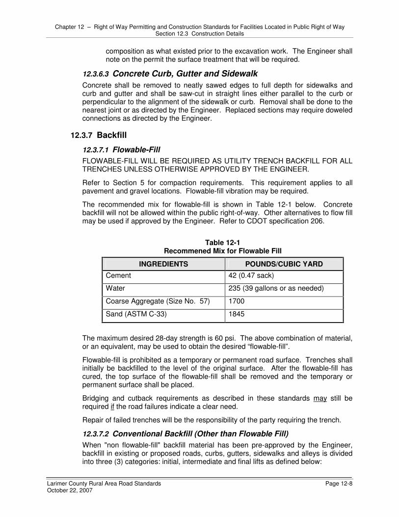
Chapter 12 – Right of Way Permitting and Construction Standards for Facilities Located in Public Right of Way Section 12.3 Construction Details
Larimer County Rural Area Road Standards Page 12-8 October 22, 2007
composition as what existed prior to the excavation work. The Engineer shall note on the permit the surface treatment that will be required.
12.3.6.3 Concrete Curb, Gutter and Sidewalk Concrete shall be removed to neatly sawed edges to full depth for sidewalks and curb and gutter and shall be saw-cut in straight lines either parallel to the curb or perpendicular to the alignment of the sidewalk or curb. Removal shall be done to the nearest joint or as directed by the Engineer. Replaced sections may require doweled connections as directed by the Engineer.
12.3.7 Backfill
12.3.7.1 Flowable-Fill FLOWABLE-FILL WILL BE REQUIRED AS UTILITY TRENCH BACKFILL FOR ALL TRENCHES UNLESS OTHERWISE APPROVED BY THE ENGINEER.
Refer to Section 5 for compaction requirements. This requirement applies to all pavement and gravel locations. Flowable-fill vibration may be required.
The recommended mix for flowable-fill is shown in Table 12-1 below. Concrete backfill will not be allowed within the public right-of-way. Other alternatives to flow fill may be used if approved by the Engineer. Refer to CDOT specification 206.
Table 12-1
Recommened Mix for Flowable Fill
INGREDIENTS POUNDS/CUBIC YARD Cement 42 (0.47 sack)
Water 235 (39 gallons or as needed)
Coarse Aggregate (Size No. 57) 1700
Sand (ASTM C-33) 1845
The maximum desired 28-day strength is 60 psi. The above combination of material, or an equivalent, may be used to obtain the desired “flowable-fill”.
Flowable-fill is prohibited as a temporary or permanent road surface. Trenches shall initially be backfilled to the level of the original surface. After the flowable-fill has cured, the top surface of the flowable-fill shall be removed and the temporary or permanent surface shall be placed.
Bridging and cutback requirements as described in these standards may still be required if the road failures indicate a clear need.
Repair of failed trenches will be the responsibility of the party requiring the trench.
12.3.7.2 Conventional Backfill (Other than Flowable Fill) When "non flowable-fill" backfill material has been pre-approved by the Engineer, backfill in existing or proposed roads, curbs, gutters, sidewalks and alleys is divided into three (3) categories: initial, intermediate and final lifts as defined below:

Chapter 12 – Right of Way Permitting and Construction Standards for Facilities Located in Public Right of Way Section 12.3 Construction Details
Larimer County Rural Area Road Standards Page 12-9 October 22, 2007
a. The INITIAL LIFT, designated as Class B and generally comprised of a
washed, clean gravel material, consists of the section from the bottom of the excavation to a point six to twelve (6 - 12) inches above the top of the installation. Placement and compaction of the initial layer shall be as specified by the utility to protect their installation.
b. The INTERMEDIATE LIFT, generally comprised of native material, consists of the section above the initial layer to a point within six (6) inches of the ground level or the bottom of the pavement section whichever is greater. Excavated material may be used in the intermediate layer provided that it is deemed suitable by the Engineer.
c. The FINAL LIFT includes both road base and asphalt surfacing. Road base material shall be CDOT Class 5 or 6 aggregate base course or as specified by the Engineer.
d. Maximum dry density of all soil types used will be determined in accordance with AASHTO T 99 or AASHTO T 180. These densities will be determined prior to placement of backfill.
e. When a hydro-hammer or drop hammer compaction machine is used for compaction of fill in trenches, the maximum layer shall be 30 inches.
12.3.7.3 Compaction Testing Requirements See “Testing” Section 12.5
12.3.7.4 Embankment and Slopes a. The Engineer shall approve all fill material. b. All cut slopes shall conform to OSHA standards.
12.3.8 Restoration
12.3.8.1 Bore Holes – Vertical and Horizontal a. For openings less than or equal to 6" in diameter, bore holes shall be filled
with patching material (cold mix is not acceptable) to prevent entry of moisture. Patching material used shall be in all cases compatible with the existing surface. Subgrade shall be replaced with flowable fill to provide necessary support to the surface. The sealing of bore holes is the responsibility of the Contractor or persons making the bore.
b. For openings greater than 6” in diameter, the limits of repair shall be identified in the permit.
c. The completed job shall be flush with the surrounding pavement and have no indentations, pockets, or recesses that may trap and hold water.
12.3.8.2 Subgrade a. Placement. The subgrade for the pavement structure shall be graded to
conform to the cross sections and profile required by the construction plans. Prior to the placement of aggregate base course or sub-course, the subgrade should be properly prepared. The subgrade should be scarified to a minimum depth of six (6) inches, moisture adjusted as necessary, and recompacted to not less than the following:

Chapter 12 – Right of Way Permitting and Construction Standards for Facilities Located in Public Right of Way Section 12.3 Construction Details
Larimer County Rural Area Road Standards Page 12-10 October 22, 2007
1) For cohesive soils, 90% maximum Modified Proctor dry density at 2% of optimum moisture content, or 95% maximum Standard Proctor dry density at 2% of optimum moisture content.
2) For non-cohesive soils, 92% maximum Modified Proctor dry density at 2% of optimum moisture content, or 97% maximum Standard Proctor dry density at 2% of optimum moisture content.
3) For expansive soils, 88% maximum Modified Proctor dry density at 3% or greater above optimum moisture content, or 93% maximum Standard Proctor dry density at 1% or greater above optimum moisture content. For highly expansive soils (swell potential 2% under 200 psf surcharge pressure), paving will not be permitted without a subgrade treatment approved by the Engineer.
b. Compaction. Prior to approval to place the base or sub-base course, all utility main and service trenches shall be compacted to not less than the above referenced densities required for the given soil classification. This density requirement also applies to all utility trenches within the public rights-of-way from a point four (4) feet beyond the edge of asphalt and descending at 1:1 outward.
12.3.8.3 Asphalt Surfacing a. Placement. Any damage, even superficial, to the existing asphalt surface in
the vicinity of the work shall be repaired at the expense of the Contractor, including but not limited to gouges, scrapes, outrigger marks, backhoe bucket marks, etc. A slurry seal type covering will be considered the minimum repair. Patching may be required, at the discretion of the Engineer. 1) The depth of asphalt patches in asphalt roads shall typically be the depth
of the existing asphalt surface plus two (2) inches or as specified by the Engineer.
2) The asphalt patch area for road excavations that fall within the wheel path of the vehicular travel lane shall be increased in size to the center of the lane or adjacent lane. In no circumstance will the edge of a patch area be allowed to fall within the wheel path.
3) Chip-sealed roads shall be treated as paved when considering an approach to repair and patching. As such, repair strategies shown in Section 12.4 shall be applied to chip-sealed roads. Full width repairs may be required by the Engineer to avoid rapid deterioration encountered with half-road patches.
4) Minimum depth of patching. i. Chip-sealed road – 4 inches ii. Local road – 4 to 6 inches iii. Collector/Minor Arterial road – 6 to 8 inches iv. Arterial road – 8 to 10 inches
5) All road cuts shall be patched as per the requirements of Section 12.4 below.
6) For roads that are less then five (5) years old the County reserves the right to deny any road excavation or require repairs that are over and above these specifications.

Chapter 12 – Right of Way Permitting and Construction Standards for Facilities Located in Public Right of Way Section 12.3 Construction Details
Larimer County Rural Area Road Standards Page 12-11 October 22, 2007
b. EXCEPTIONS - There may be situations where the patching standards are considered inappropriate. For example, rebuilding half of a road today when the road is due for reconstruction at a different profile in 2-3 years would constitute the Engineer modifying the patching requirements. In these cases, the Permit Holder may be allowed to provide a more modest patch adequate to accommodate traffic for the 2-3 year period. In return, the Permit Holder may be required to make a financial contribution to the road maintenance, rehabilitation or reconstruction program to support the more permanent improvements that are anticipated. This determination shall be made by the Engineer.
c. DISPUTE RESOLUTION - Mutual acceptance of these standards is expected to evolve over time with experience in the field. Disagreements over requirements and cost sharing are inevitable. In cases where agreement cannot be reached, the dispute shall not relieve the Contractor from compliance to the specific Permit or standards provided by this document unless approved by the Engineer.
12.3.8.4 Concrete Surfacing and Patching a. Concrete pavement shall be replaced with 4,000 psi concrete to match the
finish and thickness of the existing pavement, but not less than eight (8) inches thick. All concrete construction shall be protected from vehicular traffic, including contractor vehicles, until the concrete has achieved eighty (80) percent of its ultimate strength. Concrete shall be coated and sealed with a uniform application of membrane curing compound applied in accordance with manufacturer’s recommendations.
b. The use of quick curing concrete (3000 psi strength within 48 hours) shall be used on all arterial and collector roads when repair areas are less than 500 square feet or when temperatures are below 40° F. Quick curing concrete repairs may be opened to traffic within two (2) days or when the concrete has achieved eighty (80) percent of its design strength.
c. Where existing cracks or damage is adjacent to the area being repaired, the repair area shall include the cracked or damaged concrete. Pavement repairs shall include all areas of damage, including leak test holes, pot holes, equipment and/or material scaring of the exiting surface.
d. When repairing concrete, the removal perimeter shall be saw-cut and doweled prior to placement of new concrete as directed by the Engineer.
12.3.8.5 Joint Filling a. Asphalt. Following placement of the asphalt surface, the joints where the
new asphalt abuts the old shall be sealed with a fog or painted coat of bitumen cement.
b. Concrete. Joints shall be thoroughly cleaned of all foreign material then filled with a hot-poured elastic type joint filler conforming to M 173, ASTM D1190-80 or ASTM D1751-83, D1752-84, D3405-78, D3406-78, D3407-78 or silicone sealants or others as approved by the Engineer. Joint material shall be filled to within 1/2 inch of the surface. Excess material shall be scraped off to provide a smooth riding surface.

Chapter 12 – Right of Way Permitting and Construction Standards for Facilities Located in Public Right of Way Section 12.4 Developing a “Quality” Approach to Road Repairs
Larimer County Rural Area Road Standards Page 12-12 October 22, 2007
12.4 DEVELOPING A “QUALITY” APPROACH TO ROAD REPAIRS
12.4.1 General Every road and road repair situation is unique. Design criteria and construction standards cannot address every situation but, in order to maintain some form of consistency, these standards have been developed. In most cases, they provide the minimum acceptable standards for construction or repair. Consequently, when strictly applied, they will provide the minimum acceptable product. Therefore, this criteria has been developed to maintain the same integrity of the road pavement and subsurface condition prior to its being cut for utility installations.
To achieve the goal of “Quality” or “Excellence” in road repairs, these criteria shall be viewed as minimum standards when used in conjunction with good planning and judgment. This will restore the road to an acceptable condition with minimal patching failures. In most cases, it will be necessary to exceed the minimum standards to achieve a quality repair.
Issues that shall be considered in a quality approach to road repairs are as follows:
12.4.2 Appearance Does the final appearance of the road suggest the repairs were planned, or that they happened by accident?
1. Consciously or not, the driving public “rates” the appearance of the road system, including road repairs, every day. Road repairs which are not done satisfactorily from a functional point of view may produce a negative reaction from the public if they give the appearance of being poorly planned or executed.
2. The public’s perception of road repairs is based primarily on shape, size, and orientation -- the geometry of a patch. The following shall be considered minimum standards for the geometry of a quality patch: a. Existing pavements should be removed to clean, straight lines parallel and
perpendicular to the flow of traffic. Do not construct patches with angled sides and irregular shapes.
NOT ACCEPTABLE ACCEPTABLE

Chapter 12 – Right of Way Permitting and Construction Standards for Facilities Located in Public Right of Way Section 12.4 Developing a “Quality” Approach to Road Repairs
Larimer County Rural Area Road Standards Page 12-13 October 22, 2007
b. Avoid patches within existing patches. If this cannot be avoided, make the boundaries of the patches coincide.
Existing Patch
New Patch
NOT ACCEPTABLE
Existing Patch
New Patch
ACCEPTABLE
c. Do not “leave” strips of pavement less than one-half lane in width from the edge of the new patch to the edge of an existing patch or the lip of the gutter.
Existing Patch
New Patch
Less than 8’
Less than 8’
NOT ACCEPTABLE
Existing Patch
New Patch
ACCEPTABLE
d. In concrete pavements, remove sections to existing joints – repair “panels”. In damaged concrete, the limits of removal should be determined in the field by a representative or the Engineer.
Joints
NOT ACCEPTABLE
Joints
ACCEPTABLE
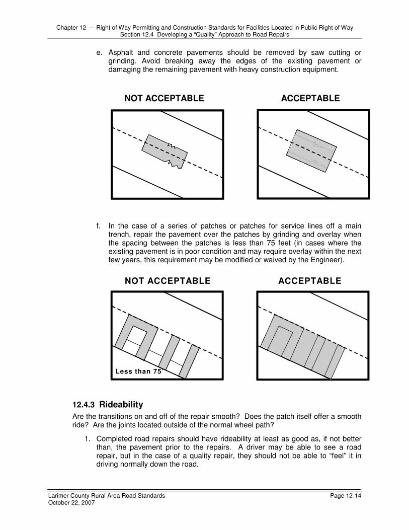
Chapter 12 – Right of Way Permitting and Construction Standards for Facilities Located in Public Right of Way Section 12.4 Developing a “Quality” Approach to Road Repairs
Larimer County Rural Area Road Standards Page 12-14 October 22, 2007
e. Asphalt and concrete pavements should be removed by saw cutting or grinding. Avoid breaking away the edges of the existing pavement or damaging the remaining pavement with heavy construction equipment.
NOT ACCEPTABLE ACCEPTABLE
f. In the case of a series of patches or patches for service lines off a main
trench, repair the pavement over the patches by grinding and overlay when the spacing between the patches is less than 75 feet (in cases where the existing pavement is in poor condition and may require overlay within the next few years, this requirement may be modified or waived by the Engineer).
Less than 75’
NOT ACCEPTABLE ACCEPTABLE
12.4.3 Rideability Are the transitions on and off of the repair smooth? Does the patch itself offer a smooth ride? Are the joints located outside of the normal wheel path?
1. Completed road repairs should have rideability at least as good as, if not better than, the pavement prior to the repairs. A driver may be able to see a road repair, but in the case of a quality repair, they should not be able to “feel” it in driving normally down the road.

Chapter 12 – Right of Way Permitting and Construction Standards for Facilities Located in Public Right of Way Section 12.4 Developing a “Quality” Approach to Road Repairs
Larimer County Rural Area Road Standards Page 12-15 October 22, 2007
2. Do not place overlays with feathered edges on roads of any classification. Overlays should be placed by first removing the existing pavement to the desired depth by grinding, and then placing the pavement flush with the adjacent surfaces.
Overlay
NOT ACCEPTABLE
Grind & Overlay
ACCEPTABLE
3. Surface tolerances for road repairs should meet the standard for new construction. That is, the finished surface of the road repair, when tested with a ten (10) foot straightedge parallel to the centerline or perpendicular across joints, will show variations measured from the testing face of the straightedge to the surface of the road repair which do not exceed one-quarter (1/4) inch.
10’ Straightedge
Greater than 1/4"
NOT ACCEPTABLE
10’ Straightedge
Less than 1/4"
ACCEPTABLE
12.4.4 Pavement Management Is the repair consistent with the long-term pavement management strategy for the particular road?
1. Road repairs should leave a pavement in a condition at least as good as, if not
better than, the condition prior to the repairs.

Chapter 12 – Right of Way Permitting and Construction Standards for Facilities Located in Public Right of Way Section 12.4 Developing a “Quality” Approach to Road Repairs
Larimer County Rural Area Road Standards Page 12-16 October 22, 2007
2. In most cases, and particularly in the cases of extensive excavation and repairs, it is desirable to survey the existing pavement condition with a representative of the County prior to the work. After completion of the work, survey the pavement condition again to verify that the pavement condition has been maintained or improved. a. In the case of minor repairs, these pavement surveys can be made by visual
observation. b. However, in the case of major projects that involve excessive haul of
materials or unusually heavy construction equipment or activity, non-destructive testing of the pavement condition before and after construction may be required.
3. Consideration of pavement management issues may also identify opportunities for joint efforts between the utilities and the County. For example, if the repair of a utility line requires an overlay on half of a road, and that the condition of the remaining half of the road warrants an overlay, the County may decide to overlay the entire road, with County and the utility splitting the cost of the overlay. In such a case, the utility may be able to save the cost of grinding half the road. Coordination for these types of cooperative repairs should occur as far in advance of actual construction as possible.
a. Transverse patches on arterial and collector roads shall be overlaid across
the entire road width for a distance of two (2) feet minimum on all sides of the trench.
NOT ACCEPTABLE ACCEPTABLE
Min
2’Min
2’
Trench

Chapter 12 – Right of Way Permitting and Construction Standards for Facilities Located in Public Right of Way Section 12.4 Developing a “Quality” Approach to Road Repairs
Larimer County Rural Area Road Standards Page 12-17 October 22, 2007
b. Do not allow the edges of patches to fall in existing wheel paths. The edges of patches parallel to the direction of traffic shall be limited to the boundaries of lanes or to the centerline of travel lanes.
NOT ACCEPTABLE ACCEPTABLE
c. Patches should have a smooth longitudinal grade consistent with the existing roadway. Patches should also have a cross slope or cross section consistent with the design of the existing roadway.
Cross Slope
Patch
NOT ACCEPTABLE
Cross Slope
Patch
ACCEPTABLE
12.4.5 Future Maintenance Will the repair pose any future maintenance problems or make future maintenance more difficult?
1. Excavations and road repairs, even when well constructed, shorten a pavement’s
life. Several types of road distress, settlement, alligator cracking, and potholes, often show up around patches. Quality road repairs should attempt to reduce the occurrence of these types of distress.
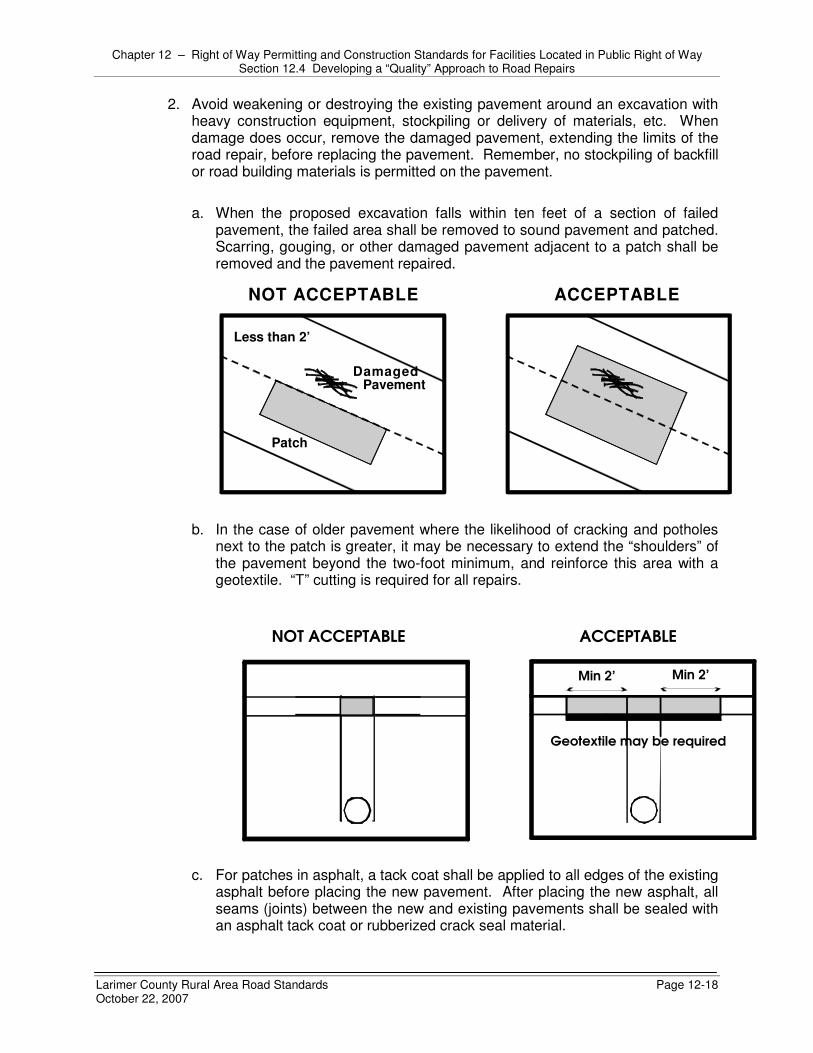
Chapter 12 – Right of Way Permitting and Construction Standards for Facilities Located in Public Right of Way Section 12.4 Developing a “Quality” Approach to Road Repairs
Larimer County Rural Area Road Standards Page 12-18 October 22, 2007
2. Avoid weakening or destroying the existing pavement around an excavation with heavy construction equipment, stockpiling or delivery of materials, etc. When damage does occur, remove the damaged pavement, extending the limits of the road repair, before replacing the pavement. Remember, no stockpiling of backfill or road building materials is permitted on the pavement.
a. When the proposed excavation falls within ten feet of a section of failed
pavement, the failed area shall be removed to sound pavement and patched. Scarring, gouging, or other damaged pavement adjacent to a patch shall be removed and the pavement repaired.
Less than 2’
Patch
Damaged Pavement
NOT ACCEPTABLE ACCEPTABLE
b. In the case of older pavement where the likelihood of cracking and potholes
next to the patch is greater, it may be necessary to extend the “shoulders” of the pavement beyond the two-foot minimum, and reinforce this area with a geotextile. “T” cutting is required for all repairs.
NOT ACCEPTABLE ACCEPTABLE
Geotextile may be required
Min 2’ Min 2’
c. For patches in asphalt, a tack coat shall be applied to all edges of the existing asphalt before placing the new pavement. After placing the new asphalt, all seams (joints) between the new and existing pavements shall be sealed with an asphalt tack coat or rubberized crack seal material.

Chapter 12 – Right of Way Permitting and Construction Standards for Facilities Located in Public Right of Way Section 12.5 Testing
Larimer County Rural Area Road Standards Page 12-19 October 22, 2007
d. Avoid frequent changes in width of patches to simply removal of adjacent pavement failures in the future.
NOT ACCEPTABLE ACCEPTABLE
12.5 TESTING
12.5.1 Description The contractor is required to provide material testing for each phase of the work at no cost to the County. The independent Geotechnical Testing Firm chosen to perform this work for the Contractor must be qualified and identified on the Permit application.
12.5.2 Testing Frequencies 1. The number of density tests required may be increased if directed by the
Engineer. The costs of any testing, as required, shall be borne by the Contractor. Proctors shall be determined prior to backfilling. Independent lab results shall be faxed to the County as soon as possible. The horizontal frequencies of density tests are as follows: a. Utility Mains - One test per 100 linear feet per lift. b. Service Lines - One test per each service per lift. c. Manholes and valve boxes per each lift.
2. Following are the minimum number of tests required for each construction activity. These tests must be submitted to the Engineer on a daily basis as acquired and shall be hand delivered or faxed to the County. a. Native or imported backfill - One (1) test for every two (2) vertical feet and
every one hundred (100) feet horizontally, or some fraction thereof with at least one (1) test per each lift.
b. Flowable-fill – Testing may be required at the discretion of the Engineer. c. Concrete pavement, curbs, gutters and sidewalks – Testing to be conducted
for every 100 cubic yards or portion thereof, with a minimum of one. The types of testing required shall be as prescribed by the County.

Chapter 12 – Right of Way Permitting and Construction Standards for Facilities Located in Public Right of Way Section 12.6 Inspection
Larimer County Rural Area Road Standards Page 12-20 October 22, 2007
d. Asphalt Pavement 1) Asphalt content – One test per 500 tons or fraction thereof of mix
produced, minimum of one test per job. 2) Gradation – Aggregate: one test per 500 tons or fraction thereof of mix
produced, minimum of one test per job. 3) In-place density – One test per 500 tons or fraction thereof of mix placed,
minimum of one test per job. e. Aggregate base course materials –One test per 400 lane feet. No less than
two (2) tests per excavation.
12.6 INSPECTION All construction work within the public rights-of-way shall be subject to inspection by the Engineer and certain types of work may have continuous inspection. It shall be the responsibility of the Contractor to provide safe access for the inspector to perform the required inspections.
It shall be the responsibility of the person performing the work authorized by the Permit to notify the Engineer when the work is ready for inspection. The Engineer requires that every request for inspection is to be received at least twenty-four (24) hours before such inspection is desired. Such requests may be in writing or by telephoning or faxing the Engineer.
The Engineer may make or require other inspections of any work as deemed necessary to ascertain compliance with the provisions of these Standards. Any work performed without the required inspections shall be subject to removal and replacement at the Contractor’s expense, regardless of the quality of the work.
Where large scale projects exceed the ability of the County to provide inspection, the Contractor or utility company will incur the cost of a private inspection firm. This inspection firm will be mutually agreed upon by the Permit applicant and the County prior to issuance of the Permit.

Larimer County Rural Area Road Standards Page A-1 October 22, 2007
APPENDIX A – DEFINITIONS AND ABBREVIATIONS
A.1 GENERAL DEFINITIONS AND ABBREVIATIONS Where the following words, phrases, or abbreviations appear in these specifications they shall have the following meanings:
� AASHTO – American Association of State Highway and Transportation Officials.
� ABC – Aggregate Base Course.
� Access Management Plan – A plan adopted by Larimer County defining access locations and requirements based on the traffic impact study evaluation of existing and proposed traffic, access points, and intersections. An access management plan supplements the Local Entity’s Transportation Master Plan, specifically adopted to regulate access on specific streets.
� ACI – American Concrete Institute.
� ADA - Americans with Disabilities Act
� AISC – American Institute of Steel Construction.
� ANSI – American National Standards Institute.
� Applicant – The person or designated agent providing pertinent information for preparation of permit, TIS, etc. This is often the Developer.
� APWA – American Public Works Association.
� ASA – American Standards Association.
� "As-Built" or Record Drawings - Set of original plans, with information superimposed upon them, showing any additions, deletions, changes, etc.
� ASTM – American Society for Testing and Materials.
� ATSSA – American Traffic Safety Services Association.
� BCC - Board of County Commissioners of Larimer County, Colorado
� Bridge – Any structure conveying a roadway or path over a body of water or other feature. Bridges shall be designed to carry a varying combination of loading, including vehicular, bicycle, and/or pedestrian traffic.
� Calendar Day – Each and every day shown on the calendar, beginning and ending at midnight.
� Capital Expansion Fee (CEF) Program – A program that has been established by Larimer County for the purpose of funding certain transportation improvements. The roads funded by a CEF Program primarily serve the overall transportation system, not just a single development.
� CDOT – Colorado Department of Transportation.
� City - Any incorporated area within Larimer County, Colorado
� CMP – Corrugated Metal Pipe.

Appendix A – Definitions and Abbreviations Section A.1 General Definitions and Abbreviations
Larimer County Rural Area Road Standards Page A-2 October 22, 2007
� Code – The latest official adopted ordinances, policies, codes, and/or regulations of Larimer County otherwise referred to as the Larimer County Land Use Code.
� Construction Plans - Detailed and working plans including plan and profile, details, notes and any other information necessary for complete construction of the required improvements.
� Consultant Engineer – A Colorado licensed professional engineer working on behalf of the Developer.
� Continuity – The continuous length of a roadway segment that is uninterrupted by 90 degree turns or controlled intersections.
� Contractor – The person, firm, or organization to whom a construction contract is awarded by the Developer, or who has been issued a right-of-way work permit by Larimer County. Agents, employees, workers, or designers employed by the Contractor are also bound by the terms of the contract or permit.
� Corner Sight Distance – The distance necessary for the driver of a motor vehicle stopped at a stop sign on a Minor Street or driveway to see approaching vehicles, pedestrians, and bicyclists along the intersecting major street and have sufficient space to make any allowed move to cross the Major Street or merge with traffic on the Major Street without causing vehicles, pedestrians, or bicyclists traveling at or near the design speed on the major street to slow down. The controlling distance for design is the longest distance, generally the distance necessary to merge with traffic.
� County - County of Larimer, State of Colorado.
� Cross Slope – Slope of the pavement surface, excluding gutter, measured perpendicular to the street centerline.
� Days – Intended as calendar days and not working days unless stipulated as working days.
� DCP – Development Construction Permit.
� Design Speed – The speed determined for design which takes into account the physical features of a street influencing vehicle operation; the maximum safe speed maintainable on a specified section of street when conditions permit design features to govern. Design speed is 5 to 10 mph higher than the posted speed limit to provide a factor of safety and allow for other conditions or uses of the street that may affect vehicle operation.
� Designer – The person or persons responsible for the creation and submission of contract documents or construction plans for the purpose of one-time construction of a facility. This person shall be a Colorado licensed professional engineer.
� Developer – The private party or parties desiring to construct a public or private improvement within Larimer County rights-of-way or easements, securing all required approvals and permits from the County, and assuming full and complete responsibility for the project.
� Development – Construction of improvements on land that is essentially vacant.
� Development Agreement (DA) – The contract between Larimer County and the Developer that defines public improvement requirements, costs, and other related public improvement issues.

Appendix A – Definitions and Abbreviations Section A.1 General Definitions and Abbreviations
Larimer County Rural Area Road Standards Page A-3 October 22, 2007
� Development Construction Meeting – A meeting between the Designer and assigned agents and the Engineer to review proposed work necessary to construct the project, prior to proceeding with the work. A meeting may be required for each project, at the Engineer’s discretion.
� Development Construction Permit – Permit to construct public or private improvements for a project or within an unimproved right-of-way, obtained by application to the Local Entity.
� Director of Public Works (DPW) – The Larimer County Director of Public Works who oversees the Engineering Department.
� Driveway – A private access with 20 trips per day or less onto a public or private roadway.
� Driveway Approach – The portion of the driveway lying in the public right-of-way or public access easement between the roadway of a public street and the right-of-way or public access easement line, for the full width of the access, including both apron and side slopes.
� Easement – The property right of the Local Entity to use lands owned in fee by a private party for the purposes of maintenance, access, drainage, or other use, as specified on a plat or deed of dedication.
� Engineer - The County Engineer, Larimer County, Colorado, or their authorized representative, acting on behalf of the County.
� FEMA – Federal Emergency Management Agency.
� FHWA – Federal Highway Administration, Department of Transportation.
� Final Acceptance – The written notification from the County, after the County finds the Warranty Period to be satisfactorily completed, that all public improvements are free of defects and the County releases the Developer from future maintenance obligations.
� FIRM – Flood Insurance Rate Map.
� Frontage – The distance along the road right-of-way line of a single property or development within the property lines. Corner property at an intersection would have a separate frontage along each street.
� GMA - Growth Management Area Overlay Zone District – The areas defined in the Larimer County Master Plan as existing or future potential annexation areas. Wherever these standards associate “GMA” with a particular city, “GMA” refers to that town or city’s annexation areas.
� HBP – Hot Bituminous Pavement. Pavements constructed with a mix of aggregate and asphaltic/bituminous cement. (Similar acronyms used by other references may include: ACP – Asphalt Concrete Pavement, HAC – Hot Asphalt Concrete, HMA – Hot Mixed Asphalt, and similar variations.)
� HMA – Hot Mix Asphalt
� IGA - Inter-Governmental Agreement
� Inspector – An authorized representative of the Engineer, assigned to make inspections to assure work is completed in compliance with plans, standards and specifications.
� Intersection Sight Distance – Refer to Corner Sight Distance.

Appendix A – Definitions and Abbreviations Section A.1 General Definitions and Abbreviations
Larimer County Rural Area Road Standards Page A-4 October 22, 2007
� ITE – Institute of Transportation Engineers.
� Landscaping – Materials including, without limitation, grass, ground cover, shrubs, vines, trees, and non-living materials, commonly used in landscape development, as well as attendant irrigation systems.
� Lane Width – The width of a travel lane measured from the centerline of the lane striping to the centerline of the parallel lane stripe.
� Lift – The maximum specified thickness of material that may be placed at one time.
� Low Volume Access – Access with daily traffic volumes between 21 and 99 vehicles.
� May – A permissive condition.
� MUTCD – Manual on Uniform Traffic Control Devices.
� Opinion of Cost (Cost Estimate) – Unit costs, based on those approved by Larimer County and assigned to materials and related quantities. The Opinion of Cost shall be broken down by Phase, when applicable, for each project and shall be submitted by the Designer at the time of first plan review by the Engineer.
� OSHA – Occupational Safety and Health Administration.
� Owner’s Engineer - A registered engineer (State of Colorado) acting for the Owner or Developer.
� P.C. – Point of curvature.
� Permittee – The holder of a valid permit issued in accordance with these Standards or other County related process.
� Phasing Plan – A plan that defines improvements to be completed in specified parts over a defined sequence.
� P.I. – Point of intersection.
� Plans – Construction plans signed by the County depicting public improvements to be constructed for the project.
� Professional Engineer (P.E.) – A Colorado licensed professional engineer.
� Professional Land Surveyor (P.L.S.) – A Colorado licensed land surveyor.
� Project – The public or private improvement(s) designated in the approved plans, which are to be constructed in conformance with these Standards. The term “Project” includes any and all public or private improvement projects for or within the Local Entity, whether development projects, private utility projects, or capital improvement projects.
� Proposed Roadway Improvements – Those roadway improvements deemed necessary due to the impact of the project development.
� P.T. – Point of tangency.
� Public Improvement Construction Plans – Detailed and working plans including plan and profile, details, notes and any other information necessary for complete construction of the required improvements. Also refer to Utility Plans.
� Public Improvements – Those public-type facilities to include: pavement, curb and gutter, sidewalk, pedestrian/bike/equestrian paths, storm drain facilities with related appurtenances, culverts, channels, bridges, water distribution or transmission facilities

Appendix A – Definitions and Abbreviations Section A.2 Definition of Road Functional Category
Larimer County Rural Area Road Standards Page A-5 October 22, 2007
with related appurtenances, sanitary sewer collection facilities with related appurtenances, water and waste water treatment facilities, pavement markings, signage and striping, traffic signals and related appurtenances, erosion control and right-of-way grading, or earth excavation processes integral to construction of other public improvements listed herein.
� Right-of-way (ROW) – (Also “public right-of-way.”) A public street, way, alley, sidewalk, or easement.
� Road or Street - A general term denoting a public or private way used for access to two or more lots, parcels, or tracts of land, including the entire area within the right-of-way and/or access easement.
� Scoping Meeting – A required meeting for the Applicant and Applicant’s traffic engineer to review all the requirements for a Transportation Impact Study.
� Shall – A mandatory condition.
� Should – An advisory condition, recommended, but not required.
� Stopping Sight Distance – The distance required by the driver of a vehicle traveling at the design speed to bring the vehicle to a stop after an object on the road becomes visible. This distance is measured from the driver’s eye, 3.5 feet above the pavement to the top of an object 6 inches high on the pavement anywhere on the roadway.
� Substantial Completion - That degree of completion of the project or a portion of the project, sufficient to provide the County the use of the project or a defined portion of the project for the purposes for which it was intended.
� TIS - Transportation Impact Study, as described in Appendix F.
� USGS – United States Geological Survey.
� Variance – A deviation from these Standards that has been duly and properly approved by the County.
� Wheel Path – The 3-foot wide wheel traveled portion located on both sides of the travel lane and starting 2 feet from the center of the travel lane.
� Working Day – 7 a.m. to 6 p.m., Monday through Friday, excluding any holidays observed by the Local Entity.
A.2 DEFINITION OF ROAD FUNCTIONAL CATEGORY All roads are divided into functional classification categories for planning purposes and are defined in the Larimer County Transportation Plan.
A.3 TERRAIN CLASSIFICATION For the purposes of this manual, the terrain in Larimer County is divided into two categories:
A. FLAT OR ROLLING TERRAIN - Average cross slope less than 15% and the ridges and draws are not steep and well defined.
B. MOUNTAINOUS TERRAIN - Average cross slope greater than 15% and the ridges and draws are steep and well defined.

Larimer County Rural Area Road Standards Page B-1 October 22, 2007
APPENDIX B – REFERENCES AND RESOURCE STANDARDS
The following Standards (the latest editions unless otherwise stated) may be used as reference material when certain design or construction methods and materials are not specifically addressed in these Standards and require approval of the Engineer. PUBLICATION AGENCY Americans with Disabilities Act
DOJ/EEOC
Bridge Design Manual CDOT
Bridge Detail Manual CDOT
Construction Manual CDOT
CADD Manual CDOT
Design Guide CDOT
Drainage Design Manual CDOT
Field Materials Manual CDOT
Highway Capacity Manual ITE
LRFD Bridge Design Specifications AASHTO
Larimer County Land Use Code LC Planning
Manual on Uniform Traffic Control Devices FHWA / US DOT
NCHRP Report 279, Intersection Channelization Guide NCHRP
Pavement Design Manual CDOT
Policy on Geometric Design of Highways & Streets AASHTO
Roadside Design Guide AASHTO
Roundabouts, an Informational Guide FHWA
Standard Plans (M & S Standards) CDOT
Standard Specifications for Highway Bridges AASHTO
Standard Specifications for Road & Bridge Construction CDOT
Standard Specifications for Transportation Materials and
Methods of Sampling and Testing
AASHTO
State Highway Access Code CDOT
Storm Water Design Standards LC Engineering
Survey Manual CDOT
Trip Generation Manual ITE

Larimer County Rural Area Road Standards Page C-1 October 22, 2007
APPENDIX C – STANDARD DRAWINGS
DRAWING 1 RURAL ARTERIAL ROAD - TYPICAL SECTION
DRAWING 2 RURAL MAJOR COLLECTOR ROAD - TYPICAL SECTION
DRAWING 3 RURAL MINOR COLLECTOR ROAD - TYPICAL SECTION
DRAWING 4 RURAL LOCAL ROAD - TYPICAL SECTION
DRAWING 5 RURAL LOCAL LOW VOLUME ROAD - TYPICAL SECTION
DRAWING 6 CUL – DE –SAC DETAIL
DRAWING 7 TYPICAL ACCESS DETAIL
DRAWING 8 STREET NAME SIGN MOUNTING AND LOCATION DETAIL
DRAWING 9 LARIMER COUNTY STREET NAME SIGNS DETAIL
DRAWING 10 GENERAL TRAFFIC SIGN LOCATION DETAIL
DRAWING 11 CULVERT DETAIL


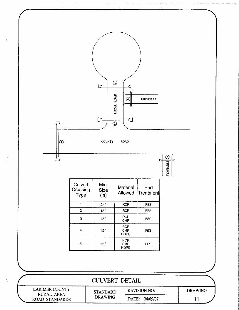

Larimer County Rural Area Road Standards Page D-1 October 22, 2007
APPENDIX D – CONSTRUCTION STANDARDS
D.1 ROADS
D.1.1 Scope The purpose of this standard is to set forth the criteria to be used in the construction of all roads within Larimer County. Subject to the Larimer County revision of these standards, all road, bridge and related construction shall be performed in accordance with the latest edition of the Colorado Department of Transportation Standard Specifications for Road and Bridge Construction and the latest version of the Colorado Department of Transportation Standard Plans M&S Standards.
D.1.2 General 1. Variances from Standards. These standards, the CDOT standards and
construction plans are intended to supplement each other. In the event there is a conflict between the two, the standards shall govern except as supported by an approved variance request. If administrative changes are made after approval of the plans, the variance from these standards must be approved in writing by the Engineer. Work shall be completed according to the design approved by the Engineer. Written clarification shall be obtained from the Engineer for approval of omissions, conflicts or revisions prior to construction.
2. Omissions. Any work not specifically set forth in the construction plans or these standards, but which is necessary as determined by the Larimer County, shall be completed.
3. Conformity of Work and Materials. All work performed and all materials furnished shall be in conformity with the lines, grades, cross sections, dimensions and material requirements, including tolerances, shown on the plans or indicated in these criteria and the specifications. It shall be the responsibility of each individual contractor to keep the work area clean during the prosecution of the work.
4. Utility Coordination. Utility coordination is the responsibility of the Developer. Relocation of utilities which are in an existing public right-of-way or existing public easement, as determined by the Engineer, shall be done at the expense of the utility involved or the Developer.
D.1.3 Regulations for Road Construction 1. Authority of Engineer. The Engineer is authorized to check all work performed
in connection with road construction, including, but not limited to, clearing and grubbing, compaction of subgrade, placement of subbase, base and asphalt, forms, concrete work and materials to be used. The Engineer may be present on the site to advise contractors on these standards, and has authority to reject defective materials and workmanship, until any questions of issue can be resolved by the Engineer, and advise the Contractor in complying with construction plans and standards. The Engineer shall, in no case, act as foreman or perform other duties for the Contractor, nor interfere with the management of the work done by the

Appendix D – Construction Standards Section D.1 Roads
Larimer County Rural Area Road Standards Page D-2 October 22, 2007
Contractor. The presence or absence of the Engineer shall not relieve, in any degree, the responsibility or the obligation of the Developer, Contractor or the Consultant. The Engineer shall, at all times, have reasonable and safe access to the work whenever it is in preparation or progress and the Contractor will provide proper facilities for such access and inspection. The Engineer has the authority to select locations for tests to be made and to require additional testing to be paid for by the Developer.
2. Notice Before Beginning Work. The Contractor shall notify the Engineer’s office a minimum of 48 hours before beginning construction.
3. Compaction in Utility Trenches, Culverts, etc. Before road construction will be permitted, all utility trenches within the road right-of-way (including service lines) must be mechanically compacted to 95% of maximum density per AASHTO T 99 or AASHTO T180 or as specified in the soils report. All water and sewer services including water and sewer main stub-outs shall be installed prior to road construction. This compaction shall extend to the road right-of-way line as a minimum. Water settlement of trenches shall not be permitted.
4. Construction Stakes. The Developer shall provide all stakes necessary for curb, gutters, walks and structures and will furnish all necessary information relating to lines and grades. The Contractor shall be held responsible for the reasonable preservation of all such stakes.
5. Work Zone Traffic Control. Work zone traffic control devices shall be maintained in a safe operating condition at all times. The Contractor shall provide, for approval by the Engineer, a work zone traffic control plan, and shall comply with the current edition of The Manual on Uniform Traffic Control Devices (MUTCD). If the Engineer finds the construction area to be inadequately protected, the Engineer has the authority to stop work and direct that corrective measures be taken prior to proceeding with work.
6. Preservation of Property. Existing improvements, adjacent property, utilities, trees and plants that are not to be removed shall be protected from injury or damage resulting from the Contractor’s operations.
7. Timeliness of Repairs. Repairs to all failed or unsatisfactory work shall be completed within 30 days after receipt of notice to repair from the Engineer unless otherwise approved by the Engineer.
8. Protection of Utility Lines. The Contractor shall at all times take proper precautions for the protection of utilities, the presence of which are known or can be determined by field locations of the utility companies.
9. Protection of Public and Private Installations. The Contractor shall at all times take proper precautions for the protection of driveway culverts, road intersection culverts or aprons, irrigation crossings, mailboxes, driveway approaches, and all other identifiable installations that may be encountered during construction. The Contractor shall be responsible for all expenses relating to damage to public and private installations.

Appendix D – Construction Standards Section D.2 Revisions to CDOT Standards Specifications for Road and Bridge Construction
Larimer County Rural Area Road Standards Page D-3 October 22, 2007
D.2 REVISIONS TO CDOT STANDARDS SPECIFICATIONS FOR ROAD AND BRIDGE CONSTRUCTION
SECTION TITLE Section
D.1 Roads
Revision of Section 105 Control of Work...........................................................................D.2.1
Revision of Section 106 Control of Material ......................................................................D.2.2
Revision of Section 202 Removal of Asphalt (Planing)......................................................D.2.3
Revision of Section 203 Excavation and Embankment .....................................................D.2.4
Revision of Section 206 Excavation and Backfill for Structures.........................................D.2.5
Revision of Section 217 Herbicide Treatment ................................................................ D.2.6
Revision of Section 304 Aggregate Base Course..............................................................D.2.7
Revision of Section 304 Treated Aggregate Base Course ................................................D.2.8
Revision of Section 308 Fly Ash Treated Subgrade ..........................................................D.2.9
Revision of Section 401 Plant Mix Pavements – General (Non-Voids Acceptance) ..........D.2.10
Revision of Section 403 Hot Mix Asphalt ..........................................................................D.2.11
Revision of Section 412 Portland Cement Concrete Pavement.........................................D.2.12
Revision of Section 601 Structural Concrete.....................................................................D.2.13
Revision of Section 609 Curb and Gutter ..........................................................................D.2.14
Revision of Section 629 Survey Monumentation...............................................................D.2.15

Appendix D – Construction Standards Section D.2 Revisions to CDOT Standards Specifications for Road and Bridge Construction
Larimer County Rural Area Road Standards Page D-4 October 22, 2007
D.2.1 Revision of Section 105 – Control of Work
REVISION OF SECTION 105 CONTROL OF WORK
Subsection 105.03 shall include the following: Conformity to the Contract of all Hot Mix Asphalt, Item 403, will be determined by tests and evaluations of asphalt content, gradation and in-place density, and will be evaluated for acceptance, rejection. Delete subsection 105.04 and replaced with the following: 105.04 Conformity to the Contract of Superpave Performance Graded Binders. Superpave Performance Graded binders shall meet all requirements of Subsection 702.01. The Contractor shall submit a Certificate of Compliance from the supplier for all binder delivered for use on the project. The Certificate of Compliance shall be prepared in accordance with subsection 106.12. A new Certificate of Compliance shall be prepared and submitted for each new lot or batch. In addition to the Certificate of Compliance the contractor shall submit a “Bill of Lading” for each load of binder delivered for use on the project. Each “Bill of Lading” shall contain the lot or batch number identical to that on the Certificate of Compliance. Binder that cannot be certified as complying with the requirements of Subsection 702.01 shall not be incorporated into the project. Material which is obviously defective may be isolated and rejected without regard to sampling sequence or location within a lot or batch. Delete subsection 105.07 and replace with the following: 105.07 Conformity to Roadway Smoothness Criteria. Roadway smoothness shall be tested as described below. Roadway smoothness testing will not be measured and paid for separately, but shall be included in the work. All longitudinal and transverse pavement surfaces will be measured using a 10 foot straightedge. The Contractor shall furnish an approved 10 foot straightedge and depth gauge and provide an operator to aid the Engineer in testing the finished pavement surface. Areas to be measured shall be as directed by the Engineer. Areas showing high spots of more that 3/16 inch in 10 feet shall be marked and diamond ground until the high spot does not exceed 3/16 inch in 10 feet. Additional diamond grinding shall be performed as necessary to extend the area ground in each lateral direction so that the lateral limits of grinding are at a constant offset from and parallel to the nearest lane line or pavement edge,

Appendix D – Construction Standards Section D.2 Revisions to CDOT Standards Specifications for Road and Bridge Construction
Larimer County Rural Area Road Standards Page D-5 October 22, 2007
and in each longitudinal direction so that the grinding begins and ends at lines normal to the pavement centerline within the ground area. All ground areas shall be neat rectangular areas of uniform surface. Diamond grinding, including all necessary traffic control, shall be completed at the Contractor’s expense. On asphalt pavements, the diamond grinding shall not reduce planned pavement thickness by more than 0.3 inch and the entire ground area shall be covered with a fog seal coat when grinding is complete. On concrete pavements, the diamond grinding shall be completed prior to joint sealing and prior to determining pavement thickness in accordance with subsection 412.21. When longitudinal tining is required on concrete pavement, the diamond ground surface shall be grooved to restore the longitudinal texture, whenever the length of the ground area exceeds 45 feet. If roadway smoothness exceeds the limits allowable for diamond grinding, corrective work on asphalt pavements shall consist of an approved overlay or removal and replacement. Corrective work on asphalt pavements shall conform to the following conditions: (a) Removal and replacement. The pavement in areas requiring corrective work shall be
removed the full width of the lane and the full thickness of the course in accordance with Subsection 202.09 Removal of Asphalt Mat (Planing).
The removal area shall begin and end with a transverse butt joint, which shall be constructed with a transverse saw cut perpendicular to centerline. All replacement shall be made with approved hot mix asphalt mixtures that meet all contract requirements. Replacement material shall be placed in sufficient quantity so the finished surface will conform to grade and smoothness requirements. The corrective area shall be compacted to the specified density.
(b) Overlay. The overlay shall cover the full width of the pavement including shoulders. The
area overlaid shall begin and end with a transverse butt joint which shall be constructed with a transverse saw cut and asphalt removal. All material shall be approved hot mix asphalt mixtures that meet all contract requirements. The overlay shall be placed so the finished surface will conform to grade and smoothness requirements. The overlaid area shall be compacted to the specified density. The overlay thickness shall be equivalent to that of the final pass made in accordance with the plans and specifications.
If roadway smoothness exceeds the limits allowable for diamond grinding, corrective work on concrete pavements shall consist removal and replacement. Corrective work on concrete pavements shall conform to the following conditions: Removal and Replacement. The pavement areas requiring corrective work shall be removed the full width of the lane and full length of the slab between horizontal control joints and shall be jointed in accordance with M-412-1 Regardless of the corrective method used, the final product shall provide a pavement surface equal to adjacent sections not requiring corrective work. All corrective work, including all necessary traffic control, shall be completed at the Contractors expense.

Appendix D – Construction Standards Section D.2 Revisions to CDOT Standards Specifications for Road and Bridge Construction
Larimer County Rural Area Road Standards Page D-6 October 22, 2007
In Subsection 105.08 delete the second paragraph and replace with the following In case of discrepancy, the order of precedence is as follows: (a) Specifications
1. Appendix D of Larimer County Specifications 2. CDOT Standard Specifications
(b) Details
1. Appendix C Standard Drawings 2. CDOT M & S Standards
(c) Approved Development Construction Plans
D.2.2 Revision of Section 106 – Control of Material
REVISION OF SECTION 106 CONTROL OF MATERIAL
Subsection 106.02 (b) shall include the following: The Contractor shall furnish evidence that Contractor source materials meet the contract specifications and shall pay for such tests as may be required to show compliance. All material shall be sampled and tested in accordance with the appropriate Colorado Department of Transportation or AASHTO procedures. Any materials lab doing work for the Contractor must be approved by the County before any testing is done. The County is mandated by state statute (Section 35-5-102, CRS) to control the spread of the following noxious weeds: Leafy spurge Euphorbia esula Canada thistle Cirsium arvense Musk thistle Carduus nutans Russian knapweed Centaurea repens Spotted knapweed Centaurea maculosa Diffuse knapweed Centaurea diffuse Yellow toadflax Linaria vulgaris Dalmation toadflax Linaria genistifolia Any source of imported embankment, topsoil, or gravel, except screened material, must be inspected and approved by the County Environmental Specialist, or designee, prior to incorporation into the project. If these materials are infested with these weeds, the Contractor must move to a different location within the area that is not infested or select another source altogether. The Contractor shall notify the County a minimum of two (2) days prior to moving any materials onto the project site in order to schedule this inspection. In the event the Contractor is unable to find a material source that is not infested, he shall be required to coordinate a treatment program with the Larimer County Weed District and the Engineer. The cost of complying with this requirement shall be included in the work.

Appendix D – Construction Standards Section D.2 Revisions to CDOT Standards Specifications for Road and Bridge Construction
Larimer County Rural Area Road Standards Page D-7 October 22, 2007
D. Excavation, Removals And Embankment
1. Scope
The work covered by this subsection concerns the furnishing of all labor, equipment, supplies and materials necessary to perform clearing, grubbing, removal of objectionable materials from the right-of-way prior to grading operations, and placement of embankment to conformity with lines, grades and typical sections as shown on the plans or as staked.
2. Clearing and Grubbing
The natural ground surface shall be cleared of all vegetation such as trees, logs, upturned stumps, roots of downed trees, brush, grass, weeds and all other objectionable materials within the limits of the construction. All surface objects and all trees, stumps, roots and other protruding obstructions, not designated to remain, shall be cleared and/or grubbed, including mowing, as required, except undisturbed stumps and roots and nonperishable solid objects which will be a minimum of 2 ft below subgrade or slope of embankments. Trees which are to be removed shall be removed in such a manner as not to injure standing trees, plants, and improvements which are to remain.
3. Removal and Disposal of Materials
All materials removed shall be disposed of outside of the right-of-way. No accumulation of flammable material shall remain on or adjacent to the right-of-way. The roadway and related work areas shall be left with a neat and finished appearance.
D.2.3 Revision of Section 202 – Removal of Asphalt
REVISION OF SECTION 202 REMOVAL OF ASPHALT (PLANING)
In subsection 202.09 delete the last paragraph and replace with the following: The longitudinal surface smoothness of the roadway shall conform to requirements of Subsection 105.07 – Conformity to Roadway Smoothness Criteria.

Appendix D – Construction Standards Section D.2 Revisions to CDOT Standards Specifications for Road and Bridge Construction
Larimer County Rural Area Road Standards Page D-8 October 22, 2007
D.2.4 Revision of Section 203 – Excavation and Embankment
REVISION OF SECTION 203 EXCAVATION AND EMBANKMENT
Subsection 203.03 (a), first paragraph, shall be deleted and replaced with the following: (a) Embankment Material. Embankment material shall consist of approved material
acquired from excavations, including Contractor’s source, hauled and placed in embankments.
Contractor’s source material shall have a minimum R-value of 15 ,and shall be equal to or greater than the design R-value required for the road when tested by the Hveem Stabilometer, have a maximum dry density of not less that 90 p.c.f., and must be stable when tested in accordance with Colorado Procedure L-3102. The Contractor shall furnish evidence that the material meets the requirements of this section and shall pay for such tests as may be required to show compliance. All materials shall be sampled and tested in accordance with appropriate CDOT or AASHTO procedures.
D.2.5 Revision of Section 206 – Excavation and Embankment for Structures
REVISION OF SECTION 206
EXCAVATION AND BACKFILL FOR STRUCTURES
Subsection 206.02(a) shall include the following: Structure Backfill shall meet the requirements of Table 703-2, aggregate base course, Class 5 or Class 6, and shall be used in all locations where Class 1 or Class 2 Structure Backfill is specified.
D.2.6 Revision of Section 217 – Herbicide Treatment
REVISION OF SECTION 217 HERBICIDE TREATMENT
Subsection 217.01 shall include the following:
Herbicides shall be applied under all new paving and shall be applied to the surface directly beneath the surfacing material. In Subsection 217.02 delete the first sentence and replace with the following:

Appendix D – Construction Standards Section D.2 Revisions to CDOT Standards Specifications for Road and Bridge Construction
Larimer County Rural Area Road Standards Page D-9 October 22, 2007
The sterilization agent (herbicide) shall be a pre-emergent herbicide, soluble, dispersible or mixable in water and non-toxic to humans when applied per the manufacture’s recommendations. The agent shall be active for one year after application.
D.2.7 Revision of Section 304 – Aggregate Base Course
REVISION OF SECTION 304 AGGREGATE BASE COURSE
Subsection 304.02 shall include the following: Materials for the base course shall be Aggregate Base Course (Class 5) as shown in subsection 703.03. The Aggregate Base Course (Class 5) must meet the gradation requirements and have a resistance value of at least 72 when tested by the Hveem Stabilometer method. The Engineer may require the Contractor to submit test results from a certified materials lab to verify the material’s conformance to the requirements of this section. Costs of any such tests shall be borne by the contractor.
D.2.8 Revision of Section 304 – Treated Aggregate Base Course
REVISION OF SECTION 304 TREATED AGGREGATE BASE COURSE
Subsection 304.02 shall include the following: Treated Aggregate Base Course (Class 5) (MGCL) shall meet the requirements of Section 304. Table 703-2 for Class 5 material shall be revised to allow 12 to 15 percent passing the #200 sieve. Subsection 304.06 shall include the following: Variation from the treated aggregate base course plan elevation specified shall not be more than 0.04 foot. Subsection 304.06(a) shall be added: Treated Aggregate Base Course (Class 5)(MGCL) shall be placed, mixed, shaped and compacted as described below: Place and compact the full width and depth of Aggregate Base Course (Class 5) in accordance with Section 304. MGCL shall then be thoroughly mixed into the upper 4 inches of the road surface by scarifying and blading the upper four inches of aggregate base course material into approximately equal windrows on each side of the road. Wet, with water, both windrowed and remaining surface materials to approximately four- percent moisture, or as directed. Apply magnesium chloride in two equal sprayed applications of 0.25 gallon per square year each. After each application, used a motor grader (and additional water as necessary to prevent

Appendix D – Construction Standards Section D.2 Revisions to CDOT Standards Specifications for Road and Bridge Construction
Larimer County Rural Area Road Standards Page D-10 October 22, 2007
segregation of the materials) to thoroughly process one half of the windrowed material to a uniform mixture. Place the processed mixture to grade and compact with a pneumatic tire roller, as specified in this section. Repeat this procedure for the material in the second windrow. Apply a final application of 0.10 gallon per square yard of magnesium chloride to the entire finished surface. Allow the magnesium chloride to soak in for thirty minutes or as needed to prevent surface displacement before final rolling. Compact the entire cross section with a steel drum roller in accordance with this section of the specifications. Do not allow traffic on the treated surface until approved.
D.2.9 Revision of Section 308 – Fly Ash Treated Subgrade
REVISION OF SECTION 308 FLY ASH TREATED SUBGRADE
Section 308 is hereby added to the Standard Specifications for this project as follows:
DESCRIPTION 308.01 This work shall consist of treating the subgrade, existing subbase or existing base by pulverization, adding Class “C” fly ash, mixing and compacting of the mixed material to the required density. This work applies to natural ground or embankment and shall be constructed as specified herein and in conformity with the typical sections, lines, and grades as show on the plans or as established by the Engineer.
MATERIALS AND EQUIPMENT (a) Fly Ash. Fly Ash shall meet ASTM Specification 618, Section 3.2, when sampled and
tested in accordance with Sections 4, 6, and 8, unless otherwise shown on the plans. Fly ash shall be of the class “C” designation containing a minimum of 25 percent CaO.
Fly ash shall be stored and handled in closed weatherproof containers until immediately before distribution on the road. If stored in bins are used; they shall be completely enclosed. Materials in bags shall be stored in weatherproof buildings with adequate protection from ground dampness. Fly ash shall be furnished in trucks, each truck shall have the weight of fly ash certified on public scales or the Contractor shall place a set of standard platform truck scales or hopper scales at a location approved by the Engineer.
(b) Water. The water used in the stabilized mixture shall be clean, clear, and free of sewage, vegetable matter, oil, acid, and alkali. Water known to be potable may be used without testing. All other sources shall be tested in accordance with AASHTO T-26 and approved by the Engineer.
(c) Equipment. The machinery, tools, and equipment necessary for proper prosecution of
the work shall be on the project site and approved by the Engineer prior to the beginning of construction operations. All machinery, tools, and equipment used shall be

Appendix D – Construction Standards Section D.2 Revisions to CDOT Standards Specifications for Road and Bridge Construction
Larimer County Rural Area Road Standards Page D-11 October 22, 2007
maintained in a satisfactory and workmanlike manner. Two self-propelled rotary type mixing machines, capable of performing the work as specified, shall be provided.
CONSTRUCTION REQUIREMENTS
308.03 General. The Contractor shall construct a completed course of treated material which contains a uniform fly ash/soil mixture with no loose or segregated areas; has a uniform density and moisture content; is well bound for its full depth; and has a smooth surface suitable for placing subsequent courses. Variation from the subgrade plan elevations specified shall not be more than 0.08 foot. Where bituminous or concrete surfacing materials are to be placed directly on the subgrade, the subgrade plane shall not vary more than 0.04 foot. It shall be the responsibility of the Contractor to regulate the sequence of his work; to process a sufficient quantity of material to provide full depth treatment as shown on the plans; to use the proper amounts of fly ash; to maintain the work; and to rework the courses as necessary to meet the above requirements. 308.04 Processing Materials.
(a) Preparation of Subgrade. Before construction operations begin, the subgrade shall be
graded and shaped to enable the fly ash treatment of materials in place in conformance with the lines, grades, and thickness shown on the plans. Unsuitable soil or materials shall be removed and replaced with acceptable material.
(b) Fly Ash Application. The fly ash shall be spread by an approved spreader at the rates
shown on the plans or as directed by the Engineer. A motor grader shall not be used to spread the fly ash.
The fly ash shall be distributed at a uniform rate and in such a manner as to reduce the scattering of fly ash by wind to a minimum. Fly ash shall not be applied when wind conditions, in the opinion of the Engineer, are such that blowing fly ash becomes objectionable to traffic or adjacent property owners.
(c) Mixing. The soil and fly ash shall be thoroughly mixed by use of at least two self-propelled rotary type mixing machines, capable of performing the work as specified and the mixing continued until, in the opinion of the Engineer, a homogenous, friable mixture of soil and fly ash is obtained, free from all clods or lumps. Water required to achieve the specified moisture content for the mixture should be added during final mixing.
If the soil/fly ash mixture contains clods, they shall be reduced in size by raking, blading, disking, harrowing, scarifying or the use of other approved pulverization methods so that when all nonslaking aggregates retained on the No. 4 sieve are removed, the remainder of the material shall meet the following requirements when tested at the field moisture condition by laboratory sieves:
Minimum Passing 1-3/4 inch sieve 100 percent Minimum Passing No. 4 sieve 60 percent
During final mixing, water shall be added to the materials as directed by the Engineer, until the proper moisture content has been secured. Water shall be added through the pulverizing machine or other method acceptable to the Engineer to develop a uniform,

Appendix D – Construction Standards Section D.2 Revisions to CDOT Standards Specifications for Road and Bridge Construction
Larimer County Rural Area Road Standards Page D-12 October 22, 2007
controlled rate addition of the needed moisture. Final moisture content of the mix, prior to compaction, shall not exceed the optimum moisture content of the mix by more than 2 percent nor by less than the optimum by more than 4 percent. Should the natural moisture content of the soil be above the specified range, aeration of the soil may be required prior to addition of the fly ash.
308.05 Compaction. Compaction of the mixture shall begin immediately after final mixing of the fly ash and be completed within one hour following addition of water to the fly ash. The material shall be sprinkled as necessary to maintain the optimum moisture. Compaction of the mixture shall begin at the bottom and shall continue until the entire depth of mixture is uniformly compacted to a specified density. All non-uniform (too wet, too dry, or insufficiently treated) areas which appear shall be corrected immediately by scarifying the areas affected, adding or removing material as required, reshaping and recompacting. The surface of the course shall be maintained in a smooth condition, free from undulations and ruts, until other work is placed thereon or the work is accepted. The stabilized section shall be compacted to the extent necessary to provide the density specified below:
For fly ash treated subgrade, existing subbase or Not less than 95 percent maximum existing base that will receive subsequent subbase dry density (ASTM D-698) or base courses. For fly ash treated subbase or base that will Not less than 96 percent maximum receive surface course. Dry density (ASTM D-698)
In addition to the requirements specified for density, the full depth of the material shown on the plans shall be compacted to the extent necessary to remain firm and stable under construction equipment. After each section is completed, tests as necessary will be made by the Engineer. If the material fails to meet the density requirements, the Engineer may require it to be reworked as necessary to meet those requirements or require the Contractor to change his construction methods to obtain required density on the next section. Throughout this entire operation the shape of the course shall be maintained by blading, and the surface, upon completion, shall be smooth and in conformity with the typical section shown on the plans and to established lines and grades. Blading should be terminated within two hours after blending of the fly ash. Should the material, due to any reason or cause, lose the required stability, density, and finish before the next course is placed or the work is accepted, it shall be reprocessed, recompacted and refinished at the sole expense of the Contract. Reprocessing shall follow the same pattern as the initial stabilization, including the addition of fly ash. 308.06 Finishing and Curing. After the final layer or course of the treated subgrade, subbase, or base has been compacted, it shall be brought to the required lines and grades in accordance with the typical sections. The resulting base surface shall be thoroughly rolled with a pneumatic tire roller and “clipped”, “skinned”, or “tight bladed” by a motor grader to a depth of approximately ¼ inch, removing all

Appendix D – Construction Standards Section D.2 Revisions to CDOT Standards Specifications for Road and Bridge Construction
Larimer County Rural Area Road Standards Page D-13 October 22, 2007
loosened stabilized material from the section. Recompaction of the loose material should not be attempted. The surface shall then be thoroughly compacted with the pneumatic roller, adding small increments of moisture as needed during rolling. If plus No. 4 aggregate is present in the mixture, one complete coverage of the section with the fat wheel roller shall be made immediately after the “clipping” operation. When directed by the Engineer, surface finishing methods may be varied from this procedure provided a dense, uniform surface, free of surface compaction planes, is produced. The moisture content of the surface material must be maintained within the specified range during all finishing operations. Surface compaction and finishing shall proceed in such a manner as to produce, in not more than two hours, a smooth, closely knit surface, free of cracks, ridges or loose material conforming to the crown, grade, and line shown on the plans. After the fly ash treated course has been finished as specified herein, the surface shall be protected against rapid drying by either of the following curing methods for a period of not less than three days or until the surface or subsequent courses are placed: (a) Maintain in a thorough and continuously moist condition by sprinkling. (b) Apply a two-inch layer of earth on the completed course and maintain in a moist
condition (c) Apply an asphalt membrane to the treated course, immediately after same is completed,
the quantity and type of asphalt approved for use by the Engineer shall be sufficient to completely cover and seal the total surface of the base between crown lines and all voids. If the Contractor elects to use this method, it shall be the responsibility of the Contractor to protect the asphalt membrane from being picked up by traffic by either sanding or dusting the surface of same. The asphalt membrane may remain in place when the proposed surface or other base courses are placed. Asphaltic emulsions are not acceptable for the asphaltic membrane.
After the fly ash treated course has been finished a specified, the treated area shall remain free of all construction & vehicular traffic for a minimum of 24 hours.
D.2.10 Revision of Section 401 – Plant Mix Pavements
REVISION OF SECTION 401 PLANT MIX PAVEMENTS – GENERAL
(NON-VOIDS ACCEPTANCE) Delete subsection 401.02(a) and replace with the following: Prior to beginning paving each calendar year, the contractor shall submit to the County for review and approval, a mix design for each mix type he proposes placing in Larimer County right of way. The County may also require mix designs from the Contractor during the year because of changes in the physical properties or source of the aggregates, or physical properties or source of the binder. Mix designs shall be developed using the SuperPave method of designing paving mixtures.

Appendix D – Construction Standards Section D.2 Revisions to CDOT Standards Specifications for Road and Bridge Construction
Larimer County Rural Area Road Standards Page D-14 October 22, 2007
(a) Mix Design. The Contractor shall submit the following to the Engineer:
A proposed plant mix pavement mix design from an independent Laboratory prepared in accordance with Colorado Procedure 52, including a proposed job-mix gradation for each mixture required by the Contract which shall be wholly within the Master Range Table, Table 703-3A, B, and C, before the tolerances shown in Table 401-1 are applied. The weight of lime shall be included in the total weight of the material passing the No. 200 sieve. The restricted zone boundaries given in the Asphalt Institutes’ SuperPave Series No. 2 (SP-2) Manual are to be used as guidelines in mix design development. However, the job-mix gradation is not required to pass above or below the restricted zone boundaries. The job-mix formula for each mixture shall establish a single percentage of aggregate passing each required sieve size, a single percentage of bituminous material to be added to the aggregate, and a single temperature for the mixture at the discharge pint of the plant. No hot mix asphalt (HMA) shall be placed prior to submittal of a mix design and approval of the job-mix formula.
Subsection 401.02(b) shall include the following:
The top layer of HBP shall not contain any reclaimed asphalt pavement. Layers below the top layer shall not contain more than 15 percent reclaimed asphalt pavement. The reclaimed asphalt pavement shall meet the requirements for subsection 703.04.
Delete subsection 401.11 and replace with the following: 401.11 Tack Coat. When ordered by the Engineer, a tack coat shall be applied between pavement courses. Tack coat shall be applied to all existing asphalt surfaces that are more than 12 hours old or have not been kept clean. Subsection 401.16 shall include the following: Thickness Tolerance. In place pavement thickness shall be determined as follows. The pavement shall be cored at 500 foot intervals, or fraction thereof, in each 12 foot lane (nominal), with a minimum of 3 cores taken for any area. The County may require additional cores to define deficient areas. Any deficiency in the total thickness of the asphaltic pavement shall not exceed ½ inch for any one sample with the average deficiency for all samples not to exceed ¼ inch. Final decision for correction of deficiencies shall be made by the Engineer.
In Subsection 401.16 delete paragraph nine (9) and replace with the following: The Engineer will delineate the areas to be evaluated and inform the contractor of the location and extent of these areas. In Subsection 401.16 delete the last paragraph and replace with the following: Coring will be done at the expense of the Contractor.

Appendix D – Construction Standards Section D.2 Revisions to CDOT Standards Specifications for Road and Bridge Construction
Larimer County Rural Area Road Standards Page D-15 October 22, 2007
D.2.11 Revision of Section 403 – Hot Mix Asphalt
REVISION OF SECTION 403 HOT MIX PAVEMENT
Subsection 403.02 shall include the following: The design mix for hot mix asphalt shall conform to the following:
TABLE 403-1
Values For All Gradings Property Test
Method (75) (100) Comments
Air Voids, percent at: N (initial) [information only] N (design)
CPL 5115 >9.5 3.5 – 4.5
>11.0 3.5 – 4.5
Lab Compaction (Gyrations): N (initial)[ information only] N (design)
CPL 5115 7 75
8 100
Stability, minimum CPL 5106 28 30 Aggregate Retained on the No. 4 Sieve with at least 2 Mechanically Induced fractured faces, % minimum
CP 45 70 70
Accelerated Moisture Susceptibility Tensile Strength Ratio (Lottman), minimum
CPL 5109 Method B 80% 80%
Minimum Dry Split Tensile Strength, kPa (psi)
CPL 5109 Method B 205 (30) 205 (30)
Grade of Asphalt Cement, All Layers See Table 403-3 and
403-4 Voids in the Mineral Aggregate (VMA) % minimum CP 48 See Table
403-2 See Table
403-2
Voids Filled with Asphalt (VFA), % AI MS-2 65 - 80 65 - 75
Dust to Asphalt Ratio: Fine Gradation
Course Gradation
0.6 – 1.2 0.8 – 1.6
0.6 – 1.2
0.8 – 1.6
Note: AI MS-2 = Asphalt Institute Manual Series 2 Note: The current version of CPL 5115 is available from the Colorado Department of
Transportation Region 4 Materials Engineer.

Appendix D – Construction Standards Section D.2 Revisions to CDOT Standards Specifications for Road and Bridge Construction
Larimer County Rural Area Road Standards Page D-16 October 22, 2007
Note: Mixes with gradations having less than 40% passing the No. 4 sieve shall be
approached with caution because of constructability problems.
Note: Table 1 of CPL 5115, which contains the laboratory mixing and compaction temperatures to be used for mix design development and laboratory verification of project produced mixtures, is deleted for this project and replaced with the following:
CPL 5115 TABLE 1
Superpave Binder Grade
Laboratory Mixing Temperature, °C (°F)
Laboratory Compaction
Temperature, °C (°F)
PG 58-28 154 (310) 138 (280)
PG 58-22 154 (310) 138 (280)
PG 64-22 163 (325) 149 (300)
PG 70-28 163 (325) 149 (300)
PG 64-28 163 (325) 149 (300)
PG 58-34 154 (310) 138(280)
PG 76-28 163 (325) 149 (300)
TABLE 403-2
Minimum Voids in the Mineral Aggregate (VMA)
Design Air Voids ** Nominal Maximum Size*,
mm (inches) 3.5% 4.0% 4.5%
37.5 (1½) 11.6 11.7 11.8
25.0 (1) 12.6 12.7 12.8
19.0 (¾) 13.6 13.7 13.8
12.5 (½) 14.6 14.7 14.8
9.5 ( � 15.6 15.7 15.8
* The Nominal Maximum Size is defined as one sieve
larger than the first sieve to retain more than 10%. ** Interpolate specified VMA values for design air voids between those listed.
In an effort to simplify the binder selection process, the following binder grades have been specified for the various types of construction and road classifications. Included in this table are the design gyration requirements.

Appendix D – Construction Standards Section D.2 Revisions to CDOT Standards Specifications for Road and Bridge Construction
Larimer County Rural Area Road Standards Page D-17 October 22, 2007
Table 403-3 Binder Grade and Design Gyration Requirements
New Construction or Reconstruction Overlay
Local PG 58-28 (75) Local / Residential PG 58-28 (75) Minor Collector PG 64-28 (75) Minor Collector PG 64-22 (75) Major Collector PG 64-28 (75) Major Collector PG 64-22 (75) Industrial / Commercial PG 64-28 (100) Industrial /
Commercial PG 64-22 (100)
Arterial PG 64-28 (100) Arterial PG 64-22 (100) Table 403-3 lists the minimums however, Larimer County may require grade bumping to account for extreme traffic flow and traffic loading conditions on Collector and Arterial roadways. This may be required on new construction, reconstruction and overlays and will be determined based on Table 403-4.
Table 403-4 Grade Bumping Criteria
Condition Binder Grade Increase Slow Moving Traffic Loads 1 Grade Higher Than Free Flowing Standing Traffic Loads 2 Grades Higher Than Free Flowing Total 18k ESAL ������������ 1 Grade Higher Than Free Flowing Total 18k ESAL ������������ 2 Grades Higher Than Free Flowing
1. Free flowing traffic is traffic at speeds greater than 45 miles/hour 2. Slow moving traffic is traffic moving between 12 miles/hour and 45 miles/hour 3. Standing traffic is traffic moving less than 12 miles per hour 4. No adjustment will be allowed for the low temperature grade because of traffic speed or
volume The Contractor shall prepare a quality control plan outlining the steps taken to minimize segregation of HBP. This plan shall be submitted to the Engineer and approved prior to beginning the paving operations. When the Engineer determines that segregation is unacceptable, the paving shall stop and the cause of segregation shall be corrected before paving operations will be allowed to resume. The top layer of HBP shall not contain any reclaimed asphalt pavement. Layers below the top layer shall not contain more than 15 percent reclaimed asphalt pavement. The reclaimed asphalt pavement shall meet the requirements for subsection 703.04. The contractor shall use an approved anti-stripping additive. The type and amount may be either of the following: Liquid Additive – The amount of additive used shall be a minimum of 0.5 percent by weight of the asphalt cement. The additive shall be added at the refinery or at the hot plant. If the liquid anti-stripping additive is added at the plant, an approved in-line blender must be used. The blender shall be in the line from the storage tank to the drier drum or pug mill. The blender shall apply sufficient action to thoroughly mix the asphalt cement and anti-stripping additive.

Appendix D – Construction Standards Section D.2 Revisions to CDOT Standards Specifications for Road and Bridge Construction
Larimer County Rural Area Road Standards Page D-18 October 22, 2007
Hydrated Lime - A minimum of 1 percent hydrated lime by mass (weight) of the combined aggregate shall be added to the aggregate for all hot mix asphalt. Subsection 403.03 shall include the following: The contractor shall construct the work such that all roadway pavement placed prior to the time paving operations end for the year, shall be completed to the full thickness required by the plans. The Contractor’s Progress Schedule shall show the methods to be used to comply with this requirement. Subsection 403.05 shall include the following: The Contractor shall collect the scale ticket on each load when it is delivered to the project site, and ensure that the information required in subsection 109.01 is shown on each ticket. The scale tickets shall be available on site for county personnel to inspect.
D.2.12 Revision of Section 412 – Portland Cement Concrete Pavement
REVISION OF SECTION 412
PORTLAND CEMENT CONCRETE PAVEMENT
Subsection 412.16 shall include the following: The Contractor shall be responsible for taking adequate steps to protect concrete placed during precipitous, hot or cold weather. Any concrete damaged by precipitation or extreme temperatures shall be removed and replaced.
It shall be the Contractor’s responsibility to protect, by the use of barricades, signs, etc., fresh concrete from damage as a result of vandalism or other causes; damaged concrete shall be repaired or removed and replaced. Subsection 412.21 shall be deleted and replaced with the following: The thickness of the pavement shall be determined by average caliper measurement of cores tested. A minimum of 2 cores per 1000 square yards will be taken at random. Should any deviation be found, additional cores may be taken to define the horizontal limits of the deviation. When measurement of the core from a unit is not deficient by more than 1/2 inch from the design thickness, the pavement thickness will be considered to be within acceptable tolerance. When such measurement is deficient more than 1/2 inch, two additional cores at intervals not less than 300 ft will be taken and used to determine the average thickness for that area. When the average thickness of pavement area is deficient by more than 1/2 inch the Engineer may require that the area be removed and replaced.
Appendix D – Construction Standards Section D.2 Revisions to CDOT Standards Specifications for Road and Bridge Construction
Larimer County Rural Area Road Standards Page D-19 October 22, 2007
D.2.13 Revision of Section 601 – Structural Concrete
REVISION OF SECTION 601 STRUCTURAL CONCRETE
In Subsection 601.14 Delete the third paragraph and replace with the following: Structural Concrete Coating shall be the final finish for all exposed concrete surfaces on concrete box culverts, bridges, headwalls and similar structures unless approved otherwise by the Engineer.
D.2.14 Revision of Section 609 – Curb and Gutter
REVISION OF SECTION 609 CURB AND GUTTER
Delete Subsection 609.01 and replace with the following: 609.01 This work consists of the construction of curb, gutter, combination curb and gutter, or combination curb, gutter and sidewalk in accordance with these specifications and in conformity with the lines and grades shown on the plans or established. The types of curb are as designated on the approved plans and in the M-standards. Subsection 609.03 (e) shall include the following: Expansion joint material shall be installed every 500’ and between newly installed concrete and any existing structures including inlets, driveways, fire hydrants, poles, sidewalk under walk culverts, mid block ramps, at radius points at intersections, and other fixed objects. Expansion joint material shall be set vertical, and have the top edge flush with the finished surface. The joint shall be edged with a suitable edging tool. Subsection 609.03 shall include the following: All underground utilities shall be installed prior to the construction of curbs, gutters, combination curb and gutter, or combination curb, gutter and sidewalk. The Contractor shall be responsible for taking adequate steps to protect concrete placed during precipitous hot or cold weather. Any concrete damaged by precipitation or extreme temperatures shall be removed and replaced.
It shall be the Contractor's responsibility to protect, by the use of barricades, signs, etc., fresh concrete from damage as a result of vandalism or other causes; damaged concrete shall be repaired or removed and replaced.

Appendix D – Construction Standards Section D.2 Revisions to CDOT Standards Specifications for Road and Bridge Construction
Larimer County Rural Area Road Standards Page D-20 October 22, 2007
D.2.15 Revision of Section 629 – Survey Monumentation
REVISION OF SECTION 629 SURVEY MONUMENTATION
Section 629 of the Standard Specifications is hereby revised for this project as follows: Subsection 629.02 Delete paragraph 2, sentence 1 and 2 and replace with the following: Monuments and Monument Boxes will be furnished by the contractor. The various types of monuments shall be constructed according to the details shown on the Standard Plan M-629-1. Subsection 629.07 shall be deleted and replaced with the following: 629.07 Monument Box. This work shall consist of installing new Monument Boxes at locations shown in the plans. Monument Boxes shall be placed in accordance with the drawing below.
Larimer County Rural Area Road Standards Page E-1 October 22, 2007
APPENDIX E – CONSTRUCTION TESTING FREQUENCIES
Soils AASHTO ASTM Frequency Sampling T87 D420 Soil Classification M145 D3282
D2488/D2487 Per soil type encountered
Moisture-Density (Proctor) Per soil type encountered Standard T99 D698 As specified in Geotechnical Report Modified T180 D1557 As specified in Geotechnical Report Density and Moisture Content T238 & T239 D2922 & D3017 "Right of Way" -Grading 1/1000 cubic yards -Embankment (Subgrade) 1/500 lf/lane (min. of 1 per street) 1’ vertical -Base Course 1/500 lf/lane (min. of 1 per street)
-Structural Backfill 1/25 lf horizontal and per 1’ vertical (Min. 3 per structure)
-Utility Trench -Main 1/100 lf horizontal & per 1.5' vertical -Services 2 per service (vertical) -Manhole/Fire Hydrants 1/2' vertical within 2' alternating directions (min. of 4)
Hot Mix Asphalt (HMA) Sampling T168 D979 Density
-Nuclear ---- D2950 1/500 lane feet (min. of 3 per street) per lift per area paved
-Coring T166 D2726 As required or directed. Establish correction for Nuclear gauge.
-Max. Theoretical (Rice) T209 D2041 As required or directed. Min. 1/2000 ton Asphalt Content 1/500 tons Solvent T164 D2172 Ignition Oven T308 D6307 Nuclear T287 D4125 Thickness D3549 Core for thickness - 1/1000 lf/lane (min 1 per
street)(4” diameter) Aggregate Gradation T27 D5444 or C136 1/1000 ton Fractured Faces D5821 Within first 1000 ton then 1/10,000 ton Lottman (CP-L 5109)(Method B) Within first 1000 ton then 1/10,000 ton
Fine Aggregate Angularity T 304 C 1252 Within first 1000 ton then 1/10,000 ton
Mix Verification Test – (to verify that field produced HMA conforms to approved JMF) Includes – Air Voids, VMA, VFA, AC Content, Rice, Gradation, Stability (HVEEM)
Within first 1000 ton then 1/10,000 ton
Concrete Sampling T141 C172 Mold and Cure T23 C31 Transportation of Cylinders T23 C31 Physical Properties 1/100 cubic yards/One per day Min. Slump T119 C143 Air Content T152 C231 Compressive Strength T22 C39 Obtaining Cores T24 C42 As required or directed Compressive Strength of Cores T24 C42 As required or directed
Aggregate Base Course Gradation T27 C136 Per source or as required or directed Moisture-Density (Proctor) Per source or as required or directed Modified T180 D1557 As specified in Geotechnical Report or
Specifications Standard T99 D698 As specified in As specified in Geotechnical Report
or Specifications Geotechnical Report Density/ Moisture Content 1/1000 lf/Lane--Min. 3 per street

Larimer County Rural Area Road Standards Page F-1 October 22, 2007
APPENDIX F – GUIDELINES FOR TRAFFIC IMPACT STUDIES
F.1 PURPOSE AND OVERVIEW A Traffic Impact Study is required to analyze the effects of a proposed development or other land use action on the transportation system in order to determine if adequate public facilities exist to serve the proposed development, and to clearly identify any improvements required to mitigate the impacts on the transportation system. The applicant for a development proposal or other land use action must submit a Traffic Impact Study as described herein.
F.1.1 Types of Traffic Impact Studies Larimer County may require Traffic Impact Studies as follows:
1. Paving Threshold Study. The County requires a Paving Threshold Study for any proposed development or land use action that will impact unpaved or gravel roads as described in Section F.4 below.
2. Intermediate Traffic Impact Study. The County requires an Intermediate Traffic Impact Study for any proposed development or land use action that will impact paved roads as described in Section F.5.
3. Full Traffic Impact Study. The County requires a Full Traffic Impact Study for a proposed development or land use action that will have a major effect upon traffic, as described in Section F.6.
4. Any proposed development or land use action which creates less than three new dwelling units or generates less than twenty-one new daily trips will not be required to submit a traffic impact study. Such development would, however, be required to pay transportation capital expansion fees in effect at the time.
F.1.2 Responsibility and Qualifications The responsibility for assessing the traffic impacts associated with a proposed development or other land use action rests with the Applicant. Paving Threshold and Traffic Impact Studies shall be prepared under the supervision of a professional engineer registered in the State of Colorado with appropriate experience in transportation and traffic engineering.
F.1.3 Scoping The applicant is required to contact the Engineer to arrange for scoping of the TIS. The purpose of the scoping is to determine and document the parameters for the study of traffic impacts for a specific development project. The parameters determined in the scoping represent general agreement between the County and the consulting engineer, but they may not be all inclusive. The Engineer retains the right to require any additional information and / or analysis to complete an evaluation of the proposed development project.
It is incumbent upon the Applicant to supply a completed Transportation Impact Study Base Assumptions Form and be prepared during scoping to discuss:
1. Previous TIS prepared for the site, if any 2. Location of the site

Appendix F – Guidelines for Traffic Impact Studies Section F.2 Defining a Traffic Impact Area
Larimer County Rural Area Road Standards Page F-2 October 22, 2007
3. Proposed access(es) and their relationship to adjacent properties and their accesses
4. Preliminary estimates of the site’s trip generation, trip adjustment factors, if any, and trip distribution at build-out
5. Proposed phasing plan and anticipated year of build-out 6. Anticipated roadway improvements 7. Special analysis needs
Completion of the TIS scoping will result in mutual agreement between the County and the Applicant regarding the level of detail and extent to which the TIS will need to address each of the following:
1. Study area for the impact analysis 2. Other development to include 3. Existing intersection counts 4. Intersections to be studied 5. Background traffic volume forecasts 6. Special Analysis needs (This may include consideration and/or comparative
analysis of modern roundabouts as intersection control type) The completed and signed base assumptions form and any attachments shall be inserted in the TIS.
F.1.4 Review by County The Engineering Department will review all traffic impact studies, with input from other county departments as needed. All studies must be approved by the Engineer.
F.2 DEFINING A TRAFFIC IMPACT AREA Traffic impacts must be analyzed within a traffic impact area. The limits of this impact area shall be based on the size and extent of the application for development approval, the existing and future land uses, and traffic conditions on and near the site. Determination of the boundaries of the traffic impact area is at the discretion of the Engineer, but is typically done in consultation with the Applicant during the scoping meeting. Because concerns related to traffic impacts due to specific land use actions can vary greatly, the determination of a traffic impact area is done on a case-by-case basis; however, at a minimum the limits of the study area should include:
A. Internal roads
B. Adjacent roads
C. Access locations and/or new intersections
D. Off-site roads to the nearest paved County collector or arterial road or state highway

Appendix F – Guidelines for Traffic Impact Studies Section F.3 Level of Service, Access, Auxiliary Lane Requirements and Passenger Car Equivalents
Larimer County Rural Area Road Standards Page F-3 October 22, 2007
E. Off-site roads where traffic from the proposed development or land use action will account for at least 20% of the average daily traffic upon build-out.
F. Off-site intersections where traffic from the proposed development or land use action:
1. Contributes a 10% impact of the peak hour traffic on any approach leg of an intersection where the intersection is operating at a level of service C or better upon build-out.
2. Contributes a 5% impact of the peak hour traffic on any approach leg of an intersection where the intersection is operating at a level of service D or worse upon build-out.
3. Impacts a specific turning movement that currently does not have an auxiliary turn lane by at least 50% of the peak hour volume warrant for an auxiliary turn.
F.3 LEVEL OF SERVICE, ACCESS, AUXILIARY LANE REQUIREMENTS AND PASSENGER CAR EQUIVALENTS
A. The acceptable level of service (LOS) (per the Highway Capacity Manual) for rural roadways in unincorporated Larimer County (outside Larimer County adopted growth management areas) is detailed in the Larimer County Land Use Code and is a LOS C.
B. Access spacing is detailed in Chapter 10 of this document.
C. Auxiliary lane warrants are included in Chapter 4 of this document.
D. Unless specifically noted, all criteria in these standards are based on automobile operations and performance. To allow for the impact of larger trucks, buses, and recreational vehicles, “passenger car equivalents” shall be determined. A passenger car equivalent of 3 for each bus and all trucks and combinations of 40 feet in length or longer, or a passenger car equivalent of 2 for each vehicle or combination at or over 20 feet in length but less than 40 feet shall be used for these purposes.
F.4 PAVING THRESHOLD STUDY
F.4.1 When a Paving Threshold Study is Required The County requires a Paving Threshold Study for any development proposal that will create more than two (2) new dwelling units or that is expected to generate more than twenty (20) new daily vehicle trips on an unpaved or gravel road in the traffic impact area.
F.4.2 Paving Threshold Study Requirements The Paving Threshold Study must include at least the following information:
1. A location map showing the development site, the boundaries of the traffic impact area, and all roads, intersections, bridges or other roadway structures in the traffic impact area.
2. Identification of all unpaved or gravel roads in the traffic impact area and a determination as to whether the gravel has been treated with chemicals for dust suppression.

Appendix F – Guidelines for Traffic Impact Studies Section F.5 Intermediate Traffic Impact Study
Larimer County Rural Area Road Standards Page F-4 October 22, 2007
3. Identification of all bridges or other roadway structures in the traffic impact area that have been determined to be structurally deficient or functionally obsolete by the Engineer.
4. Current and projected average daily traffic volumes on all unpaved or gravel roads in the traffic impact area. Projected daily traffic volumes shall be based on full buildout of the proposed development or land use action and on any committed (approved) development that would contribute to the traffic volumes on roads in the traffic impact area.
5. A brief summary of whether or not the capacity and level of service requirements for the unpaved or gravel roads will be satisfied if the proposed development or land use action is approved and constructed. If the capacity and level of service requirements will not be satisfied, describe the improvements that must be constructed to satisfy the requirements. In addition, provide a brief analysis of the adequacy of road pavements and/or bridges and roadway structures in the traffic impact area (See Section F.7, below).
F.5 INTERMEDIATE TRAFFIC IMPACT STUDY
F.5.1 When an Intermediate Traffic Impact Study is Required The County requires at least an Intermediate Traffic Impact Study for any proposed development or land use action that will generate traffic volumes that will impact the capacity, safety, or structural integrity of the roadway system. The following are examples of proposed developments or land use actions that will require an Intermediate Traffic Impact Study:
1. Rezoning. A rezoning application increasing the intensity of land use where a traffic impact study has previously been approved.
2. Plats. Any general development plan or preliminary plat meeting the following criteria, or a final plan meeting the criteria when a traffic impact study was not approved for the preliminary plat. a. Residential Plats: Residential plats with more than 2 but no more than 20
new dwelling units. b. All Other Plats: All other plats where the volume of new traffic generated will
be more than 20 but no more than 200 vehicle trips per day. Plats with access to collector or arterial roads may require an analysis of access design and location.
3. Site Plans or Special Reviews. Any site plan or special review where the volume of new traffic generated will be more than 20 but no more than 200 vehicle trips per day.
F.5.2 Intermediate Traffic Impact Study Requirements The Intermediate Traffic Impact Study must include at least the following information:
1. A location map showing the development site, the boundaries of the traffic impact area, and all roads, intersections, bridges or other roadway structures in the traffic impact area.
2. Identification of all paved roads in the traffic impact area, a description of the type of pavement, and a description of the condition of the pavement.

Appendix F – Guidelines for Traffic Impact Studies Section F.6 When A Full Traffic Impact Study is Required
Larimer County Rural Area Road Standards Page F-5 October 22, 2007
3. Identification of all existing and proposed traffic signals in the traffic impact area. 4. Identification of all bridges or other roadway structures in the traffic impact area
that have been determined to be structurally deficient or functionally obsolete by the Engineer.
5. A summary table listing each type of land use in the proposed development or land use action, the size or amount involved, the trip generation rates used, and the resultant average daily trips generated. Trip generation must be calculated using the latest data contained in the Institute of Transportation Engineers (ITE) Trip Generation manual. If several trip generation rates are listed in the ITE manual, use the highest rate or provide sufficient justification for a lower rate. Trip generation rates for any land use not easily defined using the ITE manual or from any other trip generation data source must be clearly noted.
6. The percentage distribution of trips from the proposed development or land use action to other roads in the traffic impact area.
7. Current and projected average daily traffic volumes on all roads in the traffic impact area. Projected daily traffic volumes shall be based on full buildout of the proposed development or land use action and on any committed (approved) development that would contribute to the traffic volumes on roads in the traffic impact area as well as growth in background traffic.
8. A description of capital improvements to roads in the traffic impact area that are under construction or planned by any public agency or private entity and the schedule for completing such improvements.
9. A summary of whether or not the requirements for capacity, level of service, and adequacy of pavements and structures (See Section F.7, below) for all roads in the traffic impact area will be satisfied if the proposed development or land use action is approved and constructed. If the capacity, level of service, and adequacy of pavement and structure requirements will not be satisfied, describe the improvements that must be constructed to satisfy the requirements.
F.6 WHEN A FULL TRAFFIC IMPACT STUDY IS REQUIRED
F.6.1 When a Full Traffic Impact Study is Required A Full Traffic Impact Study will be required for any proposed development or land use action that will create more than 20 new dwelling units or generate more than 200 new vehicle trips per day, or when determined to be necessary by the Engineer.
F.6.2 Full Traffic Impact Study Requirements The Full Traffic Impact Study must include at least the following information:
1. Describe the traffic impact area, including at a minimum those elements described in Section F.2. The traffic impact area must be expanded to include the following: a. All pedestrian or bicycle routes within 1 ½ mile of a school b. All routes to any public or commercial attraction within a ten minute walk or
bicycle ride from the site. c. All routes to transit facilities within a ten minute walk of the site.

Appendix F – Guidelines for Traffic Impact Studies Section F.6 When A Full Traffic Impact Study is Required
Larimer County Rural Area Road Standards Page F-6 October 22, 2007
2. Define the following study horizons for the Full Traffic Impact Study: the existing (current), short range, and long range horizons. a. Existing Horizon: The intent of the existing or current horizon is to establish a
baseline traffic condition. b. Short Range Horizon: The intent of the short term horizon is to evaluate the
immediate impacts of the project on the transportation system. The short term horizon year is defined as the point of full buildout of the proposed development or land use action. If the project is proposed to occur over multiple phases, the impacts shall be analyzed at the point of full buildout of each phase. In no case shall the short range horizon exceed five (5) years.
c. Long Range Horizon: The intent of the long range planning horizon is to evaluate the impacts of the fully developed project in the context of regional transportation planning efforts. The long range impacts are analyzed as of the end of the current Regional Transportation Plan 20-year planning horizon. If no long range analysis year is established, the long range horizon should be twenty years after the existing horizon.
3. Identify the existing, committed (approved), and proposed land uses in the traffic impact area.
4. Prepare a map of transportation facilities within the traffic impact area for both the short range and long range planning horizons including, but not limited to, all existing and proposed roads, access points, and intersections. Include committed (funded) improvements by the County or by previously approved developments or land use actions. This map should be used to graphically display average daily and peak hour traffic volumes for the existing, short range, and long range planning horizons.
5. Describe existing traffic conditions within the traffic impact area, including average daily traffic volumes for roadways and a.m. and p.m. peak hour volumes at intersections. These volumes must be based on traffic counts no more than two years old. Determine a.m. and p.m. peak hour levels of service for intersections.
6. For short range traffic projections, provide references, calculations and data sources for all trip generation estimates, as follows. Use and document the following procedures for all trip generation estimates: a. Obtain trip generation estimates or equations from the Institute of
Transportation Engineers (ITE), Trip Generation Manual. Where several trip generation rates are listed in ITE Trip Generation Manual, use the highest trip generation rate or provide sufficient justification for a lower rate.
b. Where no published trip generation rates are available, the Engineer will consider fully documented traffic volume counts for similar existing uses.
c. Trip reduction factors may be applied under the following conditions: 1) Basic requirements. Trip reduction factors may be applied to the full trip
generation estimates derived from ITE rates or equations, only after underlying assumptions of the full ITE rates have been examined. All trip reduction factors must be fully quantified and justified in the Full Traffic Impact Study or its appendix.
2) Reassigning generated trips to passby factor. Passby factor denotes trips to the proposed development that currently exist as background mainline

Appendix F – Guidelines for Traffic Impact Studies Section F.6 When A Full Traffic Impact Study is Required
Larimer County Rural Area Road Standards Page F-7 October 22, 2007
traffic. Passby traffic must still be counted at site driveways and access points, but can be taken out of the background mainline traffic. Passby rates can be used from ITE Trip Generation Manual or other transportation publications. The Full Traffic Study must clearly illustrate re-diversion of the passby trips.
3) Other adjustments to trip generation estimates. Adjustments may also be taken for internal site trips, transit use, and transportation demand management strategies (TDM). Implementation proposals must be given for optimistic adjustments from transit use and TDM strategies. Such proposals will become conditions of approval, and must be reasonably expected to occur within five years after site build-out.
d. Show the results of the trip generation calculations in a matrix table with the following information: 1) Land use 2) Unit of measurement (for example, per dwelling unit, per 1000 s.f., etc.) 3) Total number of units 4) Trip generation rates per unit for average daily traffic and peak hour
volumes 5) Total number of trips generated for average daily traffic and a.m. and p.m.
peak hours
7. Short range and long range traffic projections must also include forecasts for the growth in background traffic. Growth rates must be approved during the scoping and may be based on one of the following (and clearly documented): a. Proportion between existing traffic volumes and projected volumes from the
regional model b. Extrapolation from historical counts c. Planning analysis which considers trends in the vicinity of the traffic impact
area either through a proportion or extrapolation estimate
8. Provide trip distribution estimates for the roads and intersections in the traffic impact area, and document the basis for these estimates. Assign the traffic based on these trip distribution estimates for both short range and long range planning horizons, graphically presented on the map described in Section D, above.
9. Present the volumes for short range and long range traffic including the projected traffic for the proposed development or land use action for the a.m. and p.m. peak hour and average daily conditions. These volumes must include turn movements at intersections as well as volumes for roads in the traffic impact area.
10. Analyze the adequacy of the transportation system to handle the projected traffic for short range and long range planning years. Key elements in this analysis should include: a. Generalized daily traffic volume level of service for roadways b. Intersection levels of service for a.m. and p.m. peak hours

Appendix F – Guidelines for Traffic Impact Studies Section F.7 Additional Requirements
Larimer County Rural Area Road Standards Page F-8 October 22, 2007
c. The appropriateness of access locations and the need for future traffic signals
d. The need for auxiliary lanes (turn lanes, deceleration and acceleration lanes), including explanations of how acceleration/deceleration lengths, storage lengths, and taper lengths were determined
e. Sight distances
11. If the County has determined that the proposed development includes or affects high hazard locations, provide traffic accident data for all roadways in the study area. The accident data shall cover a minimum period of two years prior to the proposed study time. Accident data summaries for county roads may be obtained from the County Engineering Department.
12. Provide a summary of conclusions and recommendations from the Full Traffic Impact Study, including at least the following items: a. A summary listing of traffic impacts from the proposed development on
existing and proposed roads, intersections, and traffic signals in the traffic impact area.
b. A summary listing of improvements needed to assure adequate service and safety levels on the roadway system affected by the proposed development. Identify and describe each proposed improvement, how and when it will be funded, and expected completion dates.
F.7 ADDITIONAL REQUIREMENTS In addition to the above requirements, the following shall be provided upon the request of the Engineer:
A. Roadway Surface and Structural Integrity Analysis. Provide the following:
1. Analyze the existing structural integrity of all roads in the traffic impact area significantly impacted by the proposed development. The Engineer may require analysis of affected roadways outside the traffic impact area.
2. Identify impacts from additional site generated traffic on the existing surface. Identify improvements needed to maintain surface and structural integrity at acceptable County standards.
3. The Engineer may require pavement cores if historic composite thicknesses are not available.
B. Structural Analysis of Bridges. Provide the following analysis for structurally deficient or functionally obsolete bridges impacted by the proposed development.
1. Analyze current conditions of any structurally deficient or functionally obsolete bridges.
2. Evaluate impacts of added site generated traffic upon such bridges. 3. Identify structural or operational improvements needed to maintain the safe
operation of such bridges satisfactory to the Engineer.

Appendix F – Guidelines for Traffic Impact Studies Section F.7 Additional Requirements
Larimer County Rural Area Road Standards Page F-9 October 22, 2007
Attachment A Transportation Impact Study
Base Assumptions
Project Information
Project Name
Project Location
TIS Assumptions
Type of Study Full: Intermediate:
Study Area Boundaries North: South:
East: West:
Study Years Short Range: Long Range:
Future Traffic Growth Rate
Study Intersections 1. All access drives 5.
2. 6.
3. 7.
4. 8.
Time Period for Study AM: 7:00-9:00 PM: 4:00-6:00 Sat Noon:
Trip Generation Rates
Trip Adjustment Factors Passby: Captive Market:
Overall Trip Distribution SEE ATTACHED SKETCH
Mode Split Assumptions
Committed Roadway Improvements
Other Traffic Studies
Areas Requiring Special Study
Date: Traffic Engineer:
Larimer County Engineer:

Larimer County Rural Area Road Standards Page G-1 October 22, 2007
APPENDIX G – DESIGN AND CONSTRUCTION STANDARDS FOR PRIVATE LOCAL ACCESS ROADS
G.1 GENERAL
G.1.1 Purpose The purpose of the following design standards is to safeguard life, limb, property and the public welfare by regulating construction of private local access roads serving either multiple residences or businesses that serve the general public. They also provide design recommendations for private roads accessing single residences. The regulations are intended to:
• Establish reasonable minimum standards for emergency access and roadway safety
• Encourage that private local access roads and driveways meet these standards while minimizing the amount of site disruption caused by such construction.
These minimum design standards for safe, maintainable roadways should balance the desire to preserve the natural terrain and landscapes of rural areas in the County while maintaining fairness and respect for individual rights. These standards are not intended to inhibit creative design, provided that safety is maintained and site disturbance is minimized, nor are they intended to prevent development of private property in Larimer County. The intent is to encourage roadways which “fit” with the natural terrain while providing safe, functional roads. Maximum creativity in design is encouraged when designing rural access roads.
G.1.2 Administration 1. General. Permitting for, and enforcement of, this regulation shall be
administered through the Larimer County Engineering Department by the County Engineer or his designated representative. The final design of the road is intended to be a cooperative effort between the landowner, the Engineer and other consulting parties as needed. Administration of this regulation shall be driven by the objective of attaining site-specific road design and construction that will meet the minimum requirements for reasonable emergency access, roadway safety, protection of soil and water natural resources and that respects the landowner’s individual rights.
2. Administrative Appeal. In order to assure a flexible, site specific design process, deviations from the standards may be granted for some requirements at the discretion of the Engineer. Deviations from the design standards must be considered on a site by site basis and must assure that the final design of the road will not unduly compromise the minimum requirements for emergency access and roadway safety. Such deviations must be granted in writing by the Engineer.
3. Enforcement. After August 23, 1999, construction of a private local access road which accesses more than one residential property (Multiple Access Road), without proper permitting and certification is a violation of this regulation. If the road is not in compliance, proper permitting and reconstruction of the road to
Appendix G – Design and Construction Standards for Private Local Access Roads Section G.2 Private Road Construction Permit Requirements
Larimer County Rural Area Road Standards Page G-2 October 22, 2007
meet the standards as described in this regulation must be completed before its use as a Multiple Access Road. The County may enforce this regulation by any legal or equitable means recognized by the Colorado Revised Statutes, Colorado Court Rules, and/or common law. Remedies may include, but are not limited to, denial, withholding or revocation of permits, certificates or other forms of authorization to use or develop any land, structure or improvements; and initiation of court actions for injunctions, abatement, mandamus, or damages. No Larimer County Access Permit, to access a public County road, shall be granted for a private multiple access road unless it is shown to be constructed to meet the minimum requirements of this regulation.
G.2 PRIVATE ROAD CONSTRUCTION PERMIT REQUIREMENTS
G.2.1 Multiple Access Roads A Private Road Construction Permit is required prior to new construction of private local access roads that are:
• intended to access multiple residences or • private roads accessing businesses that are used by the general public in
Larimer County. Private Road Construction Permit applications will be reviewed by the Engineer or designated representative of the Larimer County Engineering Department. A site inspection may be required if sufficient information is not included with the application. In such cases a Pre-Application Inspection Report will be generated by the County Engineer. Issuance of permits requires satisfactory compliance with the Larimer County Design Standards for Private Local Access Roads.
G.2.2 Exception for Roads Built Before August 23, 1999 Multiple access roads built before August 23, 1999 are exempt from these standards. The road must have been used as multiple access historically prior to this date for the exemption to apply. Otherwise it is considered a change of use and must meet these minimum standards. The Engineer will, at the owner’s request, certify reconstruction of the road to conform to these County standards. In such cases the requirements of this document will apply, including associated fees.
G.2.3 Certification of Single Access Roads A permit is not required to construct the road to a single residence. The Engineer will, however, at the owner’s request, certify the new construction, or reconstruction, of these roads as being built to Larimer County recommended standards. This may be done by applying for a Private Road Construction Permit and following the procedures set forth in this document for local access road construction. Any applicable inspection fees will apply.
G.2.4 Requirements for Application Application for a private road construction permit must be accompanied by a plan of sufficient clarity to indicate the nature and extent of the work. The plan must show sufficient topography to estimate the general longitudinal profile of the proposed road, extent of cuts and fills, and location of drainages, wetlands, and water features. The

Appendix G – Design and Construction Standards for Private Local Access Roads Section G.3 Engineered Design
Larimer County Rural Area Road Standards Page G-3 October 22, 2007
plan must give the location of the work, the name of the owner, the name of the person who prepared the plan, and the contractor proposed to accomplish the work, if applicable. The plan must include the following specific information:
1. A copy of the Pre-application Inspection Report from the Larimer County Engineering Department, if applicable.
2. Horizontal alignment of the proposed road shown on a topographic map of sufficient scale to allow cut and fill volumes and longitudinal profile to be estimated.
3. Locations, dimensions, and designed flow capacity of proposed drainage structures such as culverts.
4. Typical cross-sections of the road design showing width, drainage feature dimensions, depth of road surfacing materials, and proposed sub-grade treatment. A cross section must be shown for each major change in design parameters.
5. Location of any buildings, structures, natural drainages, wetlands, and water features within 100 feet of the grading work or that may be affected by the proposed grading work.
6. An erosion control plan specific to the site conditions delineating temporary and permanent mitigation measures to minimize erosion and sediment transport. See Larimer County Stormwater Design Standards, June 20, 2005, Addendum to Volume 3 of the USDCM, for examples of accepted Best Management Practices for such mitigation measures.
G.3 ENGINEERED DESIGN In some cases, where the safety or functionality of the road is compromised by complicated or unstable geology, large stream crossings, or other complicated drainage issues, an engineered design may be required by the Engineer. In these cases the application must be accompanied by appropriate drainage reports, soils engineering reports and/or engineering geology reports as required by the Engineer. The plans and specifications must be prepared and signed by an individual licensed by the State of Colorado to prepare such plans or specifications. The engineer preparing the plans must inspect as necessary and certify that the grading was done in accordance with the final approved plan.
G.4 RESOLUTION OF CONFLICTS In cases where irreconcilable differences arise between the Engineer and the applicant, the applicant may request a variance as described in Chapter 1 of the Larimer County Rural Area Road Standards.
G.5 NOTICE OF COMPLETION The applicant must notify the Engineer or the designated official when the road is ready for final inspection. Final approval will not be given until all work, including installation of all drainage facilities and their protective devices, and all erosion control measures, has been completed in accordance with the final approved plan, and any required certifications are submitted.
Appendix G – Design and Construction Standards for Private Local Access Roads Section G.6 Fees
Larimer County Rural Area Road Standards Page G-4 October 22, 2007
G.6 FEES Application fees for plan review and field inspection(s) must be paid before the Road Construction Permit is granted. Payment of final inspection fees shall be paid before final acceptance/certification is granted.
G.7 ROAD DESIGN STANDARDS Private local roads accessing multiple residential parcels (multiple access roads) or serving businesses that will involve travel by the general public must be constructed to the following standards. Although the standards are considered to be minimums to provide a safe, functional road, they represent the idealized situation where few physical constraints exist. A typical cross section is represented in Figure 1. Many areas in rural Larimer County possess unique physical attributes which make it necessary to construct the road to fit the individual site circumstances. Deviations from the minimum standards herein, to address such problems, must be shown on the construction plans at time of permit application. Field changes must be approved in writing by the Engineer or his designated representative. They must also be shown on as-built drawings at the time of final inspection.
For roads accessing single family residences, the standards herein can be used as design guidelines. While construction of such roads to the Larimer County standards is optional, it is highly recommended and will benefit the landowner. Individuals wishing to certify construction of these roads to County standards may apply for a Private Road Construction Permit and comply with the following road design standards. All fees will apply. Reconstruction of pre-existing roads to comply with the standards may be certified in the same manner.
G.7.1 Road Width
G.7.1.1 Roads accessing multiple lots (Multiple access roads) A driveable all-weather road surface width of 20 feet is required for an adequate two-way roadway to assure safe ingress and egress of emergency response vehicles. A narrower width for short distances, to minimize cut volumes or address other environmental concerns, may be acceptable if adequate turnouts are incorporated into the design and the road design is demonstrated to be otherwise safe and maintainable. The minimum acceptable width in these cases is 12 feet and must incorporate appropriate turnouts as described in Section G.7.6.
G.7.1.2 Roads accessing single lots A driveable all weather road surface width of 12 feet is recommended to assure safe ingress and egress of emergency response vehicles. To minimize cut volumes, or if topography makes this width impractical, a narrower width, for short distances, may be acceptable if the road design is demonstrated to be otherwise safe and maintainable. The minimum acceptable width in these cases is 10 feet.
G.7.1.3 Clearance height Access roads through forested areas must maintain proper clearance heights above the traveled way sufficient to allow passage of emergency vehicles. Tree branches must be trimmed to obtain a minimum overhead clearance of 13 feet 6 inches.

Appendix G – Design and Construction Standards for Private Local Access Roads Section G.7 Road Design Standards
Larimer County Rural Area Road Standards Page G-5 October 22, 2007
G.7.2 Road Grade Road design must incorporate a maximum longitudinal slope of 8% (10% in mountainous terrain). Road designs exceeding these longitudinal slopes must ensure that other safety and site disturbance guidelines are not compromised. Where topography requires, steeper grades may be necessary. The Engineer may grant deviations in writing for unusual cases in mountainous or hilly terrain. However, the average grade for 200 feet should not exceed 12%.
G.7.3 Horizontal Road Curve Radii of curvature on centerlines may be a minimum of 100 feet (60 feet in steep terrain), so long as adequate sight distance exists to allow a safe stopping distance. Mountainous terrain may require a deviation from this standard if topography is steep. The Engineer must approve such variance.
G.7.4 Vertical Road Curve For safety reasons, design of crest vertical curves (top of hill crests) must be based on the design speed of the road. The design speed must take into account sight distance limitations which result from extreme crest vertical curves. Correspondingly, sag vertical curves (bottom of hill) must also be designed based on the design speed, such that headlight visibility will not be compromised in nighttime or dim light conditions. Recommended design speed for most local access roads is 15 mph in steep, mountainous areas and 25 mph in rolling to flat areas.
G.7.5 Road Intersections Intersections should be within ten degrees of perpendicular for at least 50 feet from intersection centerlines with adequate sight distance both directions. If topography allows, grades should flatten to 3% or less for at least 50 feet approaching intersections.
G.7.6 Dead End Roads Dead end multiple access roads must be constructed with a vehicular turnaround area at the end or within the last 600 feet of roadway. Single access roads exceeding 600 feet in length should incorporate this standard as well. Turnarounds may take a number of forms (Figure 2), including a traditional cul-de-sac bubble, a hammerhead or “T” shape, or a turning loop. Cul-de-sac bubbles and turning loops must have a minimum radius of 40 feet. T’s must have a minimum length of 35 feet on both sides. For roads narrower than 20 feet, turnouts must be provided at approximately every 600 feet of road. Greater distances may be allowable if good sight distance is maintained between adjacent turnouts. The turnouts must be constructed to allow turning movements to be made by emergency vehicles (Figure 2). Turnouts must be an all weather road surface at least 8 feet wide and 30 feet long.
Note: Though not a requirement in the design for 20 ft wide roads, turnouts should be considered if the road is the single access and egress point to the parcels served.
G.7.7 Cuts and Fills Roadways should follow existing contours to the extent possible. Roadway cuts and embankments should be considered only to the extent they are necessary to maintain

Appendix G – Design and Construction Standards for Private Local Access Roads Section G.7 Road Design Standards
Larimer County Rural Area Road Standards Page G-6 October 22, 2007
safe geometric conditions for the design speed. Construction of cuts and fills in these cases must be constructed to the following requirements to maximize the safety and integrity of such work.
G.7.7.1 Cuts a. General. Unless otherwise recommended in an approved soils engineering
or engineering geology report, cuts must conform to the provisions of this section.
b. Slope. The slope of cut surfaces must be no steeper than is safe for the intended use and must be no steeper than 1 unit vertical in 1.5 units horizontal (66.7% slope) in common soil. Cut slopes in competent rock may be vertical when less than 3 feet high. Cut slopes in competent rock greater than 3 feet high and less than 8 feet high must be no greater than 1 unit vertical to 3 unit horizontal. Cut slopes greater than 8 feet high, or where unstable or compromising geology occurs, may require a soils engineering or an engineering geology report, or both, stating that the site has been investigated. Such reports must provide a recommended slope configuration to stabilize the constructed cut. When required by the Engineer, the report must be prepared and signed by an individual licensed by the state to prepare such plans and specifications. Construction of such cut slopes must conform to the recommendations of the report. Cut slopes must be seeded to reestablish appropriate vegetative cover to maximize slope stability and minimize erosion. Existing topsoil on the site must be saved and stockpiled for dressing the slope prior to seeding. Mulching of the soil surface after seeding is required to minimize erosion and protect seeds while germination and plant establishment take place. These requirements may be subject to appeal when slope material not conducive to plant growth and establishment make it inappropriate. In these cases it may be necessary to use other physical or mechanical means to stabilize the slope material. Best Management Practices (BMP) and information about seeding and revegetation are available in the Larimer County Storm Water Design Standards. Copies are available at the Larimer County Engineering Department.
G.7.7.2 Fills a. General. Unless otherwise recommended in an approved soils engineering
report, fills must conform to the provisions of this section. b. Preparation of Ground. Fill slopes must not be constructed on natural
slopes steeper than 1 unit vertical in 2 units horizontal (50% slope). The ground surface must be prepared to receive fill by removing woody vegetation such as shrubs, topsoil and other unsuitable materials and scarifying to provide a bond with the new fill. Where slopes are steeper than 1 unit vertical in 5 units horizontal (20% slope) and the height is greater than 5 feet, stability must be achieved by benching at the toe into sound bedrock or other competent material.
c. Fill Material. Composition of fill material must follow these requirements:
i. Detrimental amounts of organic material will not be permitted in fills.

Appendix G – Design and Construction Standards for Private Local Access Roads Section G.7 Road Design Standards
Larimer County Rural Area Road Standards Page G-7 October 22, 2007
ii. Rock sizes greater than 12 inches in maximum dimension iii. must be placed 2 feet or more below grade, measured vertically. iv. Rocks must be placed so as to assure filling of all voids with well-
graded soil. v. The upper 2 feet of fill must be compacted for stability in
preparation for placement of surfacing material.
d. Slope. Fill slopes must be no steeper than 1 unit vertical in 2 units horizontal (50% slope) unless the fill is engineered and constructed in such a way as to establish stability at a steeper slope. Design of such fills must be done by an individual licensed by the state to do such work. Fill slopes must be seeded to reestablish appropriate vegetative cover to maximize slope stability and minimize erosion. Whenever possible, existing topsoil on the site must be saved and stockpiled for dressing the slope prior to seeding.
G.7.7.3 Slope Setbacks These setback recommendations are included for general consideration to avoid conflicts and potential problems with other landowners. They should be followed when planning a road or other excavations.
a. General. Cut and fill slopes should be set back from site boundaries in accordance with this section. Setback dimensions are horizontal distances measured perpendicular to the site boundary. Setback dimensions should be as shown in Figure 3.
b. Top of Cut Slope. The top of cut slopes should not be made nearer to a site boundary line than one fifth of the vertical height of cut with a minimum of 2 feet and a maximum of 10 feet.
c. Toe of Fill Slope. The toe of fill slope should be made not nearer to the site boundary line than one half the height of the slope with a minimum of 2 feet and a maximum of 20 feet. Where a fill slope is to be located near the site boundary and the adjacent off-site property is developed, special precautions should be incorporated in the work, as necessary, to protect the adjoining property from damage as a result of such grading. These precautions may include but are not limited to: 1) Additional setbacks. 2) Provision for retaining or slough walls. 3) Mechanical or chemical treatment of the fill slope surface to minimize
erosion. 4) Provisions for the control of surface waters.
G.7.8 Drainage Plans for adequate site and roadway drainage are required for all road construction. Road design must contain provisions for stormwater drainage sufficient to achieve a standard of no ponding at all locations. Adequate design must insure the natural drainage system will be maintained and erosion is minimized.

Appendix G – Design and Construction Standards for Private Local Access Roads Section G.7 Road Design Standards
Larimer County Rural Area Road Standards Page G-8 October 22, 2007
1. Single Access Roads. Single-residence driveways should provide cross culverts or structures crossing natural drainages as needed to maintain natural drainage patterns and conduct stormwater away from the roadway. These culverts should, at a minimum, be sized to pass the flow generated by a 10-year storm. They should be at least 12 inches in diameter and have a minimum cross-sectional area of at least 0.78 square feet. When voluntary certification is desired, all such structures must appear on the road grading plan and be accepted by the Engineer before a permit can be issued.
2. Multiple Access Roads. Road systems accessing multiple residences (e.g. rural subdivisions) must provide cross culverts, as needed, to maintain natural drainage patterns and distribute stormwater away from the roadway. Such structures must be sized to pass at least the flow generated by a 10-year storm. Culverts may not be smaller than 18 inches in diameter nor have cross-sectional area of less than 1.77 square feet. The Engineer may require more stringent design criteria as necessary for safety and protection of property and natural drainage patterns. Adequate sizing of such structures will be determined at the planning and design stage for such road systems and must be accepted by the Engineer before a road construction grading permit is issued.
3. Culvert Specification. Culverts must be either double-wall corrugated plastic or single wall corrugated metal pipe. Single-wall pipe may be acceptable if it can be demonstrated that it meets the minimum requirements of this section. A minimum of 12 inches of cover of material compacted to manufacturer’s specifications is recommended unless manufacturers specifications indicate a lesser amount is sufficient to achieve the required bearing capacity. The culvert must be of sufficient strength and proper installation to assure a minimum of 10 tons bearing capacity.
4. Bridge Specification. Bridges must be constructed to comply with the general specifications of Chapter 7 of the Larimer County Rural Area Road Standards.
G.7.9 Erosion Control and Site Reclamation Erosion control and site reclamation improvements are required as part of every permitted road construction and excavation project. A plan to control stormwater along the roadway to lessen the degree of concentration of stormwaters must be incorporated in the erosion control plan. The plan must incorporate erosion control and site restoration measures to 1) assure effective stabilization of soil materials so that displacement and transport of soil materials is minimized and 2) affect restoration of natural vegetative ground cover to disturbed areas. In many cases the most effective means of controlling erosion is reestablishment of vegetation on disturbed areas. It is recommended that natural vegetation be left intact to the greatest extent possible.
Recommendations for erosion control techniques and revegetation practices are outlined in Larimer County Stormwater Design Standards, June 20, 2005, Addendum to Volume 3 of the USDCM. If road construction will disturb one acre or greater, a Stormwater Construction Permit is required from the Colorado Department of Public Health and Environment.
G.7.10 Buffer Zones for Streams, Intermittent Streams and Wetlands For roads which follow perennial stream corridors, a minimum 50-foot buffer zone of undisturbed vegetation must be maintained between the roadway or from any fill

Appendix G – Design and Construction Standards for Private Local Access Roads Section G.7 Road Design Standards
Larimer County Rural Area Road Standards Page G-9 October 22, 2007
material generated by the construction of the road and the normal high-water line of the stream. Proper revegetation of cut and fill slopes or other means of erosion and stormwater control must be affected to protect water quality of the stream. The Engineer may grant deviations from this buffer requirement if it can be demonstrated that the effects of such construction will not degrade water quality.
Construction of roadways within intermittent streams or drainageways shall not be permitted except for purposes of crossings. Proper design to allow adequate flow of stormwater, as indicated by the normal high-water line, must be incorporated in the plan. A buffer of at least 20 feet of undisturbed ground and vegetative cover from the normal high-water line must be maintained for roadways paralleling these features.
A 50- foot buffer zone must be maintained for wetlands unless further encroachment has been approved by the U.S. Army Corps of Engineers. Delineation of the wetland may be required by a qualified person to properly identify the extent of the wetland boundaries.
G.7.11 General Considerations Planning and construction of these roads should take into consideration all aspects of the effects of such construction activities. Among these should be consideration of encroachment upon critical wildlife habitat, wetlands conservation, protection of water quality in local streams, ponds and lakes, esthetics, etc. Site specific variances from the above standards to mitigate such concerns shall be considered so long as roadway safety and emergency access are maintained. Applicants are encouraged to study these issues and seek help from appropriate agencies or individuals to assess all effects of the proposed construction as a part of the planning process.
G.7.12 Other Permits and Conditions Issuance of a Private Road Construction Permit does not exempt the applicant from acquiring other permits regarding other local, State or Federal requirements.

Appendix G – Design and Construction Standards for Private Local Access Roads Section G.7 Road Design Standards
Larimer County Rural Area Road Standards Page G-10 October 22, 2007
NOTE: Total road width may be reduced to 12’ (10’ in unusual cases) with constant 4% cross slope for single access roads. Turnouts at maximum intervals of 600’ should be at least 30’ long.
Figure 1 - Private Local Access Road Typical Cross Section
Natural slope
Cut slope 1.5:1 common
1’ minimum or as required for adequate culvert cover
Compacted subgrade Minimum 4” All-weather surface
(gravel, crushed rock, etc.)
2:1 maximum fill slope
3% 3%
20’ CL

Appendix G – Design and Construction Standards for Private Local Access Roads Section G.7 Road Design Standards
Larimer County Rural Area Road Standards Page G-11 October 22, 2007

Appendix G – Design and Construction Standards for Private Local Access Roads Section G.7 Road Design Standards
Larimer County Rural Area Road Standards Page G-12 October 22, 2007
Figure 3. Slope Setback Requirements

Appendix G – Design and Construction Standards for Private Local Access Roads Section G.7 Road Design Standards
Larimer County Rural Area Road Standards Page G-13 October 22, 2007
EXHIBIT 1 Date August 23, 1999 PUBLIC WORKS DIVISION APPEALS PROCESS ROAD CERTIFICATION - PRIVATE LOCAL ACCESS ROADS
In the event that an applicant does not agree with a decision made pursuant to this regulation by
an employee within the Engineering Department, the applicant may, by written request
submitted to the Public Works Division not later than 30 days after the date the decision was
made, appeal the decision to the County Engineer. The County Engineer will meet with the
applicant and either affirm, reverse or modify the lower decision. If the County Engineer’s
decision is unsatisfactory to the applicant, the applicant may, by written request submitted to the
Public Works Division not later than 30 days after the date the decision, appeal the decision to
the Director of Public Works, who will meet with the applicant and either affirm, reverse or
modify the lower decision.
In the event that the Director of Public Work’s decision is unsatisfactory to the applicant, the
applicant may, by written request, appeal the matter to the County Commissioners. The County
Commissioners will hold a public hearing on the matter upon 15 days written notice to the
applicant (which notice may be waived by the applicant) and render a written decision within a
reasonable time thereafter.
__________________________________ Director of Public Works
Larimer County Rural Area Road Standards Page H-1 October 22, 2007
APPENDIX H – GENERAL NOTES
H.1 PROFESSIONAL ENGINEER CERTIFICATION Construction plans must include the following statement on the cover sheet:
These construction plans for (name of subdivision, development, or project) were prepared by me (or under my direct supervision) in accordance with the requirements of the Road Standards and the Stormwater Design Standards for Larimer County."
Name of Engineer Name of Firm Date
H.2 INDEMNIFICATION STATEMENT The engineer who has prepared these plans, by execution and/or seal hereof does hereby affirm responsibility to the county, as a beneficiary of said engineer’s work, for any errors and omissions contained in these plans, and approval of these plans by the Larimer County Engineering Department shall not relieve the engineer who has prepared these plans of any such responsibility. Further, to the extent permitted by law, the engineer hereby agrees to hold harmless and indemnify Larimer County, and its officers and employees, from and against all liabilities, claims, and demands which may arise from any errors and omissions contained in the plans
H.3 STANDARD SIGNATURE BLOCK The standard signature block shall be all sheets including the cover sheet.
Reviewed by:____________________________________________________________ LARIMER COUNTY ENGINEERING DATE

Appendix H – General Notes Section H.4 General Standard Notes for Construction Plans
Larimer County Rural Area Road Standards Page H-2 October 22, 2007
H.4 GENERAL STANDARD NOTES FOR CONSTRUCTION PLANS Submissions shall include a General Notes sheet with the following General Notes, where applicable. Please contact the Larimer County Engineering Department for current General Notes.
A. General Notes
1. Larimer County will not be providing ongoing management, monitoring,
inspection or supervision of this project to insure compliance with the approved construction drawings, and all applicable standards and specifications. This responsibility falls upon the developer/owner, their managers, engineers, and contractors. Upon project completion, Larimer County will require extensive documentation, such as professional engineer’s site/drainage/material testing certification letters, material testing records, record drawings, and field inspection reports, to demonstrate that this project is in compliance with the approved construction drawings, and all applicable standards and specifications. These documents must be prepared by licensed engineers and land surveyors.
2. No work may commence within any improved or unimproved public Right-of-Way until a Right-of-Way Construction Permit and/or Development Construction Permit is obtained from the Larimer County Engineering Department.
3. Right of Way Construction Permits and Fees will be required for utility installations (i.e. phone, cable, gas, other dry utilities) and street cuts in Larimer County Right of Way. The fees will be paid prior to issuance of the Development Construction Permit and are a part of the Development Construction Permit issuance procedure.
4. The Developer shall be responsible for obtaining all necessary permits from all applicable agencies prior to commencement of construction. The Developer shall notify the Larimer County Engineering Department (498-5700) at least 2 working days prior to the start of any earth disturbing activity, or construction on any and all public improvements. If the Larimer County Engineering Department is not available after proper notice of construction activity has been provided, the Developer may commence work in the Engineer Departments absence. However, the Larimer County Engineering Department reserves the right not to accept the improvement if subsequent testing reveals an improper installation.
5. The Developer shall submit a Construction Traffic Control Plan, in accordance with MUTCD, to the Larimer County Engineering Department for approval, prior to any construction activities within, or affecting, the Right-of-Way. The Developer shall be responsible for providing any and all traffic control devices as may be required by the construction activities. The traffic control plan and associated implementation must be done by a certified traffic control company.
6. All materials, workmanship, and construction of public improvements shall meet or exceed the standards and specifications set forth in the Larimer County Rural Area Road Standards and applicable state and federal regulations. Where there is conflict between these plans and the specifications, or any applicable standards, the most restrictive standard shall apply.

Appendix H – General Notes Section H.4 General Standard Notes for Construction Plans
Larimer County Rural Area Road Standards Page H-3 October 22, 2007
7. All references to any published standards shall refer to the latest revision of said standard, unless specifically stated otherwise.
8. These public improvement construction plans shall be valid for a period of two years from the date of approval by the Larimer County Engineering Department. Use of these plans after the expiration date may require a new review and approval process by the Larimer County Engineering Department prior to commencement of any work shown in these plans.
9. All sanitary sewer, storm sewer, and water line construction, as well as power and other “dry” utility installations, shall conform to the Governing Authority standards and specifications current at the date of approval of the plans by the Larimer County Engineering Department.
10. It shall be the responsibility of the Developer to verify the existence and location of all underground utilities along the route of the work before commencing new construction. The Developer shall be responsible for unknown underground utilities.
11. The Developer shall be responsible for protecting all utilities during construction and for coordinating with the appropriate utility company for any utility crossings required or utility relocation due to a utility conflict with the proposed improvements shown on these plans. The developer shall complete any utility work in a timely fashion and with a minimum disruption of service and shall be responsible for contacting, in advance, all parties affected by any disruption of any utility service as well as the utility companies. The developer shall contact the Utility Notification Center of Colorado (UNCC) at 1-800-922-1987, at least 2 working days prior to beginning excavation or grading, to have all registered utility locations marked. Other unregistered utility entities (i.e. ditch / Irrigation Company) are to be located by contacting the respective representative. If a conflict exists between existing and proposed utilities and/or a design modification is required, the Developer shall coordinate with the engineer to modify the design. Design modification(s) must be approved by the Larimer County Engineering Department prior to beginning construction.
12. No work may commence on any public storm water, sanitary sewer or potable water system until the Developer notifies the utility provider. Notification shall be a minimum of 2 working days prior to commencement of any work. At the discretion of the water utility provider, a pre-construction meeting may be required prior to commencement of any work.
13. All utility installations within or across the roadbed of new residential roads must be completed prior to the final stages of road construction. For the purposes of these standards any work above the subgrade is considered final stage work. All service lines must be stubbed to the property lines and marked so as to reduce the excavation necessary for building connections.
14. Portions of Larimer County are within a floodplain overlay district. The Larimer County Land Use Code should be referred to for additional criteria for improvements within these districts.
15. The Developer shall be responsible for all aspects of safety including, but not limited to, excavation, trenching, shoring, traffic control, and security. Refer to OSHA Publication 2226, Excavating and Trenching.
16. The Work hours for any work requiring an Engineers inspection shall be 7:00 A.M. to 6:00 P.M.- Monday through Friday. More restrictive hours of operation

Appendix H – General Notes Section H.4 General Standard Notes for Construction Plans
Larimer County Rural Area Road Standards Page H-4 October 22, 2007
(9:00 A.M. to 3:00 P.M.) may be in place for mainline County Road improvements depending on the location and nature of the improvements being constructed. Work requiring an Engineers inspection will not be permitted on weekends or holidays, unless requested in writing by the contractor and approved by the County in writing.
17. The Developer is responsible for providing all labor and materials necessary for the completion of the intended improvements shown on these drawings, or designated to be provided, installed, or constructed, unless specifically noted otherwise.
18. Dimensions for layout and construction are not to be scaled from any drawing. If pertinent dimensions are not shown, contact the Designer for clarification, and annotate the dimension on the record drawings.
19. The Developer shall have, onsite at all times, one (1) signed copy of the approved plans, one (1) copy of the appropriate standards and specifications, and a copy of any permits and extension agreements needed for the job. If, during the construction process, conditions are encountered which could indicate a situation that is not identified in the plans or specifications, the Developer shall contact the Designer and the Larimer County Engineering Department immediately.
20. The Designer shall provide, in this location on the plan, the location and description of the nearest survey benchmarks (1) for the project as well as the basis of bearings. The information shall be as follows:
Benchmarks—Local Entity survey. B.M.Number___________________, Elev.=_____________________, Description_______________________________________________.
21. All stationing is based on centerline of roadways unless otherwise noted. 22. Upon completion of construction, the site shall be cleaned and restored to a
condition equal to, or better than, that which existed before construction, or to the grades and condition as required by these plans. Any existing improvements destroyed, damaged or removed due to construction of this project, shall be replaced or restored in like kind at the Developer’s expense, unless otherwise indicated on these plans, prior to the acceptance of completed improvements.
23. The Larimer County Engineering Department shall not be responsible for the maintenance of roadway and appurtenant improvements, including storm drainage structures and pipes.
24. Approved Variances are listed as follows: (Plan set should have a list of all applicable variances for the project).
B. Grading and Erosion Control Notes
1. All grading and erosion control measures are subject to General Notes on the cover sheet of these plans as well as the Grading and Erosion Control Notes listed here.
2. A State Construction Dewatering Wastewater Discharge Permit is required if dewatering is required in order to install utilities or water is discharged into a storm sewer, channel, irrigation ditch or any waters of the United States.

Appendix H – General Notes Section H.4 General Standard Notes for Construction Plans
Larimer County Rural Area Road Standards Page H-5 October 22, 2007
3. The Developer shall comply with all terms and conditions of the Colorado Permit for Storm Water Discharge (Contact Colorado Department of Health, Water Quality Control Division, (303) 692-3590), the Storm Water Management Plan, and the Erosion Control Plan.
4. Temporary erosion control during construction shall be provided as shown on the Erosion Control Plan and shall be maintained in good repair by the Developer. Temporary erosion control measures shall not be removed until such time as all tributary-disturbed areas are sufficiently stabilized as determined by the Larimer County Engineering Department. When temporary erosion control measures are removed, the Developer shall be responsible for the clean-up and removal of all sediment and debris from all drainage and other public facilities.
5. Silt and sediment, within Right-of-Way, shall be removed after each substantial rainfall. The Developer shall be responsible for insuring that no mud or debris shall be tracked onto the existing public street system. Mud and debris must be removed within 24 hours by an appropriate mechanical method (i.e. machine broom sweep, light duty front-end loader, etc.) or as approved by Larimer County Engineering Department.
6. All perimeter erosion control measures shall be installed and functional, prior to any other earth-disturbing activity. All other structural erosion control measures shall be implemented as soon as the facilities, around which they are based, become operational.
7. Any erosion control facility damaged or destroyed prematurely, by any means, shall be immediately repaired by the Developer.
8. There shall be no earth-disturbing activity outside the limits designated on these plans.
9. Top soil shall be removed and stock piled prior to overlot grading operations. 10. Conditions in the field may warrant erosion control measures in addition to what
is shown on these plans. The Developer shall implement whatever measures are determined necessary, as directed by the Larimer County Engineering Department.
11. Negative impacts to downstream areas caused by overlot grading are to be monitored and corrected by the Developer. Any off-site clean-up, directed by The Larimer County Engineering Department, (including street cleaning), shall be completed within 24-hours of written instruction, or risk construction stoppage.
12. All areas disturbed by this project shall be seeded and mulched in accordance with these specifications after grading completion. a. All areas for seeding shall be tilled to break up rooting restrictive layers, have
a minimum of 4 inches of topsoil reapplied, and then be harrowed, and rolled or packed, to prepare the required firm seed bed.
b. The seed bed shall be well-settled and firm, but friable enough so that seed can be placed at the seeding depths specified. The seed bed shall be reasonably free of weeds.
c. All seeding areas shall be fertilized, unless field evidence or laboratory soil analysis indicates sufficient amounts of nitrogen (N) and 40 pounds available phosphate (P205) per acre. Time of application will be as applicable to the kind of fertilizer and type of equipment used.

Appendix H – General Notes Section H.4 General Standard Notes for Construction Plans
Larimer County Rural Area Road Standards Page H-6 October 22, 2007
d. Seed shall be planted with a drill on all slopes of 3:1 or flatter. The drill must have the capability of handling the kind and rate of seed being planted. Seed may be broadcast by mechanical spreader, or by hydraulic equipment on areas that are small, too steep, or not accessible for drill seed-operations. Seeding rates shall be doubled when using broadcast or hydraulic seeding. Hydro mulching is allowed on slopes steeper than 4:1.
e. Seed planted with a drill shall be covered with soil to a depth of 1/4 to 3/4 inch. Seed planted by the broadcast method shall be incorporated into the surface soil, to a maximum depth of 3/4 inch, by raking, harrowing, or other proven methods.
f. Mulch shall consist of either cereal grain straw or grass hay, at least 50% by weight, being 10 inches or longer. Application rate to be 2000 lbs/acre to achieve a stubbled surface. Anchoring with a mulch crimper is acceptable, or with the use of a disc plow, set vertical to the ground with sufficient weight to achieve a crimping depth of at least 4 inches into the soil. All mulched areas shall be tackified after crimping. Tackifier, whether placed on soil or mulch, shall conform to the Colorado Highway Specifications, Section 213.02. Apply tackifier with a spray nozzle, dispensing a mist that will uniformly cover the surface.
g. All seeded areas shall be mulched, crimped, and tackified within 24 hours after seeding; otherwise, areas shall be reseeded, at the Developer’s expense, prior to the mulching, crimping, and tackifying.
h. All slopes steeper than 4:1 shall be tackified after the completion of seeding and fertilizing. Steep slopes or areas with unstable soil may also require soil retention blankets. Soil retention blankets shall be placed smoothly, but loosely, on the soil surface, without stretching. The upslope end shall be buried in a trench 6 inches wide by 6 inches deep beyond the crest of the slope, to avoid undercutting. There shall be a 6-inch overlap wherever one roll of blanket ends and another begins, with the uphill blanket placed on top of the downhill blanket. There shall be a 4-inch overlap wherever 2 widths of blanket are applied side by side. Insert staples in a pattern according to the manufacturer’s recommendation, at approximately 2 staples per square yard. “T” shaped pins shall not be used.
i. To aid in germination, some form of irrigation may be required and it is the responsibility of the Developer to perform any and all necessary operations to that end.
13. The following is the specific seed mix to be used at this site (insert mix):
C. Street Improvements Notes
1. All street construction is subject to the General Notes on the cover sheet of these plans as well as the Street Improvements Notes listed here.
2. The Larimer County Engineering Department should be notified of utility work, subgrade proof rolls, base course proof rolls, and paving operations. In addition, one or both of the Developer/Owner’s Inspecting Engineer and the Developer/Owner’s Materials Testing Engineer should be present. The Larimer County Engineering Department should be given at least twenty-four hours advance notice. If a Larimer County Engineering Department representative can

Appendix H – General Notes Section H.4 General Standard Notes for Construction Plans
Larimer County Rural Area Road Standards Page H-7 October 22, 2007
not be present for these activities, these activities may still be conducted, as long as the Developer/owner’s Inspecting Engineer and/or the Developer/Owner’s Materials Engineer are present.
3. Proof rolls should be performed on subgrade prior to placement of road base, and on road base prior to placement of asphalt. All failed areas or material which exhibits excessive pumping or deformation shall be reworked, replaced or otherwise modified to form a smooth, non-yielding surfaces. Following precipitation, all areas should be re-proofrolled as needed based upon the evaluation of the Larimer County Engineering Department. Chemically treated subgrade will require proofrolling to demonstrate the adequacy of the chemical stabilization. Non paved roads will only require one proofroll on subgrade prior to placement of road base to demonstrate stability, however it is strongly recommended that additional proofrolls be performed by the contractor. Proofroll inspection and compaction test results must be approved by the Developer/Owner’s Materials Testing Engineer.
4. For a mechanical "proof roll", the entire subgrade and/or base material must be rolled with a heavily loaded vehicle having a total GVW of not less than 50,000 lbs. and a single axle weight of at least 18,000 lbs. with pneumatic tires inflated to not less that 90 p.s.i.g. “Proof roll” vehicles shall not travel at speeds greater than 3 m.p.h. during the proofroll.
5. The pavement section design, signed and stamped by a Colorado licensed Engineer, should be included in the construction plan set. Prior to paving, the asphalt mix design must be approved and certified by the Larimer County Engineering Department.
6. Where proposed paving adjoins existing asphalt, the existing asphalt shall be saw cut from the existing edge to create a clean construction joint. The Developer shall be required to remove existing pavement to a distance where a clean construction joint can be made. Wheel cuts shall not be allowed.
7. The top 12 inches of street subgrades shall be scarified and re-compacted prior to subbase installation. No base material shall be laid until the subgrade has been inspected and approved by the Developers material testing engineer.
8. Valve boxes and manholes are to be brought up to grade at the time of pavement placement or overlay. Valve box adjusting rings are not allowed, unless otherwise directed by the utility company.
9. When an existing asphalt street must be cut, the street must be restored to a condition equal to or better than its original condition. The existing street condition shall be documented by the Larimer County Engineering Department before any cuts are made. Patching shall be done in accordance with the Larimer County Street Repair Requirements specified in the Larimer County Rural Road Standards. The finished patch shall blend in smoothly into the existing surface. All large patches shall be paved with an asphalt lay-down machine. In streets where more than one cut is made, an overlay of the entire street width, including the patched area, may be required. The determination of need for a complete overlay shall be made by the Larimer County Engineering Department at the time the cuts are made.
10. All traffic control devices shall be in conformance with these plans or as otherwise specified in M.U.T.C.D. (including Colorado supplement) and as per the Right-of-Way Construction Permit traffic control plan.

Appendix H – General Notes Section H.4 General Standard Notes for Construction Plans
Larimer County Rural Area Road Standards Page H-8 October 22, 2007
11. Signage, such as site entrance signs, will not be allowed within the ROW of Larimer County roads that are external to and/or adjacent to the development construction project. Please note that all signs that are not a part of the approved construction plans will require a separate sign permit from the Larimer County Building Department.
12. The project materials testing engineer shall take asphalt cores. These cores shall be taken to verify asphalt layer thickness and the thickness of the aggregate base course. Asphalt cores should not be larger than 4 inches in diameter. Asphalt coring can be performed on the completed section once all lifts of asphalt have been placed. Asphalt coring frequency shall be, at a minimum, every 500 feet across the centerline and at least one core for an auxiliary turn bay. All core-drilled holes shall be flow filled, vibrated and then topped with HBP or permapatch material. permapatch.
13. When improvements are made to Larimer County Roads, such as paving gravel roads, all survey monuments must be improved and upgraded per the State of Colorado standards. This may include, but is not necessarily limited to, raising and upgrading monuments and the placement of a range box at each monument.
14. All recommendations of the final geotechnical engineering study (name of the study and date) by (Engineering Firm) shall be followed and implemented.
D. Traffic Signing and Pavement Marking Construction Notes
1. Prior to the commencement of any construction that will affect traffic signs of any type; the contractor shall contact the Larimer County Engineering Department.
2. The Developer is responsible for all costs for the initial installation of traffic signing and striping for the Development
3. All symbols, including arrows, ONLYS, crosswalks, stop bars, etc. shall be 0.125 mil pre-formed thermo-plastic.
4. All lane lines for asphalt pavement shall receive one coat of latex paint with glass beads, unless otherwise specified by the Engineer and/or in these plans.
5. All lane lines for concrete pavement should be epoxy paint. 6. Prior to permanent installation of traffic striping and symbols, the Developer shall
place temporary tabs or tape depicting alignment and placement of the same. Their placement shall be approved by the Larimer County Engineering Department prior to permanent installation of striping and symbols.
7. Pre-formed thermo-plastic applications and epoxy applications shall be applied as specified in CDOT Standard Specifications for Road and Bridge Construction.
8. All surfaces shall be thoroughly cleaned prior to installation of striping or markings.
9. All signage shall be per Larimer County Standards and these plans or as otherwise specified in MUTCD.
10. A field inspection of location and installation of all signs shall be performed by the Larimer County Engineering Department. All discrepancies identified during the field inspection must be corrected before the 2-year warranty period will begin.
11. The Developer installing signs shall be responsible for locating and protecting all underground utilities.

Appendix H – General Notes Section H.4 General Standard Notes for Construction Plans
Larimer County Rural Area Road Standards Page H-9 October 22, 2007
12. Special care shall be taken in sign location to ensure an unobstructed view of each sign.
13. Signage and striping has been determined by information available at the time of review. Prior to initiation of the warranty period, the Engineer reserves the right to require additional signage and/or striping if the Engineer determines that an unforeseen condition warrants such signage according to the MUTCD or the CDOT M and S Standards. All signage and striping shall fall under the requirements of the 2-year warranty period for new construction (except fair wear on traffic markings).
14. Sleeves for sign posts shall be required for use in islands/medians. 15. Roadside delineators shall be as specified in the MUTCD or the CDOT_M and S
Standards.
E. Storm Drainage Notes
1. The Larimer County Engineering Department shall not be responsible for the maintenance of storm drainage facilities located on private property or in developments. Maintenance of onsite drainage facilities shall be the responsibility of the property owner(s).
2. All recommendations of the final drainage and erosion control study (name of the study and date) by (Engineering Firm) shall be followed and implemented.
3. Prior to final inspection and acceptance by The Larimer County Engineering Department, certification of the drainage facilities, by a registered engineer, must be submitted to and approved by the Engineering Department.
F. Waterline Note
1. The minimum cover over water lines is 4.5 feet and the maximum cover is 5.5 feet unless otherwise noted in the plans and approved by the governing Water Utility.


Larimer County Rural Area Road Standards Page I-1 October 22, 2007
APPENDIX I – VARIANCE REQUEST SUBMITTAL FORM
Larimer County Rural Area Road Standards Page I-2 October 22, 2007
LARIMER COUNTY ROAD STANDARDS VARIANCE REQUEST SUBMITTAL FORM
Project Name: ______________________________________________________
Project Location: ______________________________________________________
______________________________________________________
Identify the Larimer County Rural Area Road Standards (RARS) standard that is being requested to be waived or varied and reference the appropriate section number. ________________________________________________________________________
_________________________________________________________________________
__________________________________________________________ ________
On a separate sheet, please address the following:
-Note why the standard is unfeasible or is not in the public interest. -Identify the proposed alternative design or construction criteria. -Compare the proposed design with the standard specified in the RARS and note what impacts the proposed design will have upon capital, maintenance requirements, and costs.
“I hereby certify that that the variance will not be detrimental to the public health, safety, and welfare nor will it reduce the design life of the improvement or cause Larimer County additional maintenance costs.” Signature of Engineer:_____________________________________Date:____________
Attach Seal & Signature
(COUNTY USE ONLY) � Approved � Denied Signature:_______________________
Date:____________