
Largest Mesh Deployable Antenna Technology
22
The Space Congress® Proceedings 1982 (19th) Making Space Work For Mankind Apr 1st, 8:00 AM Largest Mesh Deployable Antenna Technology Largest Mesh Deployable Antenna Technology B. C. Tankersley Harris Corporation B. E. McIntosh Harris Corporation Follow this and additional works at: https://commons.erau.edu/space-congress-proceedings Scholarly Commons Citation Scholarly Commons Citation Tankersley, B. C. and McIntosh, B. E., "Largest Mesh Deployable Antenna Technology" (1982). The Space Congress® Proceedings. 4. https://commons.erau.edu/space-congress-proceedings/proceedings-1982-19th/session-9/4 This Event is brought to you for free and open access by the Conferences at Scholarly Commons. It has been accepted for inclusion in The Space Congress® Proceedings by an authorized administrator of Scholarly Commons. For more information, please contact [email protected].
Transcript of Largest Mesh Deployable Antenna Technology

The Space Congress® Proceedings 1982 (19th) Making Space Work For Mankind
Apr 1st, 8:00 AM
Largest Mesh Deployable Antenna Technology Largest Mesh Deployable Antenna Technology
B. C. Tankersley Harris Corporation
B. E. McIntosh Harris Corporation
Follow this and additional works at: https://commons.erau.edu/space-congress-proceedings
Scholarly Commons Citation Scholarly Commons Citation Tankersley, B. C. and McIntosh, B. E., "Largest Mesh Deployable Antenna Technology" (1982). The Space Congress® Proceedings. 4. https://commons.erau.edu/space-congress-proceedings/proceedings-1982-19th/session-9/4
This Event is brought to you for free and open access by the Conferences at Scholarly Commons. It has been accepted for inclusion in The Space Congress® Proceedings by an authorized administrator of Scholarly Commons. For more information, please contact [email protected].

LARGE MESH DEPLOYABLE ANTENNA TECHNOLOGY STATUS AND PERFORMANCE ASSESSMENT
Dr. B. C. Tankersley and Mr. B. E. Mclntosh Harris Corporation Melbourne, Florida
Abstract
Preliminary assessments by both gov ernment and industry indicate that appli cations exist in the areas of communica tions, radio astronomy, and Earth observa tions requiring large, space based antennas. The mesh deployable antenna, based on its demonstrated success in the smaller aperture range, provides a promising near term capability for satisfying a significant number of these space-based applications. In this article the technology status of mesh deployable antennas is reviewed and design concepts applicable to very large mesh deployable reflectors are discussed. The present state-of-the-art performance is presented along with projections of potential performance improvement. These are compared with identified focus missions from the NASA Large Space Structures Technology (LSST) Program.
I. Background
Numerous user surveys conducted by NASA as well as the results from the Industry Workshop on Large Space Structures conducted by Langley Research Center (NASA CR-2709) support the future need for deployable antennas in the 30 to 100 meter diameter range. In general, applications in communications, Earth observations and radio astronomy dictate a need for large space antennas.
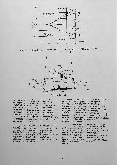
An indication of projected future antenna requirements is shown in Figure 1. This figure illustrates regions where it is expected that specific types of antennas will be applicable. There are two broad categories: deployable and erectable. The deployable category has been further subdivided into two regions: precision deployables and mesh deployables. The erectable category will ultimately encom pass an antenna type sometimes referred to as "manufacturable".
Capabilities of the deployables lie in either the high-frequency region or in the large-diameter region, but probably not both in the same antenna. The most challenging demands, characterized by the simultaneous requirements of large diameter and high surface accuracy, are not expected to be achieved by deployable technology. The boundaries between these regions are somewhat arbitrary, and those shown in Figure 1 are based on an understanding of present technology and on its likely evolution.
II. Present Mesh Deployable Antenna Designs [Reference 1}
Concepts for self-deployable reflector antennas that have been developed to the point of detail design include the dual surface, radial rib antenna from the Harris Corporation; the wrap-rib antenna from Lockheed Missiles and Space Corporation (LMSC), and the parabolic, erectable truss antenna from the General Dynamics Corpo ration. Some of these designs are well- known and are documented in the open literature, but salient features regarding each concept are briefly described below.
1. Harris Corporation Radial-Rib Antenna (Reference 2)
Harris Corporation has developed the radial-rib concept in flight hardware for the 4.8 meter Tracking and Data Relay Satellite System (TDRSS). On the TDRSS Program the mechanical, thermal, and RF performance of the design has been demonstrated. The analytical models used for design and performance prediction have also been verified.
Figure 2 illustrates the deployable reflector design. The reflector utilizes eighteen graphite fiber reinforced epoxy (GFRE) ribs to shape and support the reflec tive mesh surface. The number of ribs is based on a trade-off considering surface tolerance and weight. As the number of ribs increases, the surface error decreases, while weight increases. The minimum number of ribs consistent with the surface tolerance requirements is, therefore, usually selected. The ribs are circular in cross- section tapering from 1.5-inches diameter at the root to 0.75-inches at the tip. The rib is constructed of 4 plies at HMS graphite oriented in a 90°, 0°, ^45° configuration. The resulting wall thick ness is 0.016-inch. The reflective mesh surface is attached to the ribs by adjustable standoffs and therefore the tolerance on rib shape is not a critical parameter. The ribs are typically fabricated to a constant radius of curvature rather than a parabolic shape.
The reflective mesh (Figure 3) consists of 1.2 mil diameter, gold-plated, molybdenum wire which is knitted into a soft (low spring rate), elastic mesh. The mesh opening size can be varied to ensure adequate RF reflec tivity for a given requirement. The mesh opening size for the TDRSS reflector is 0.1 inches. The required reflector surface
9-2

1000
100
M
o
0.03
0.3
E o
yLU>
10 100
DIAMETER, mFigure 1. Types of Large Space Antennas
1000
MOLYBDENUM MONOFILAMENT 1.2 MIL, 12/IN.
SUBREFLECTOR
AU PLATED MOLY WIRE, 1.2MKDIA, TRICOT KNIT, 10 ENDS/INCH
Figure 2. TDRSS Single Access Antenna
Figure 3. Molybdenum Wire Mesh
9-3

tolerance is achieved with minimum weight through the use of a secondary drawing surface technique. This technique is illustrated in Figure 4. A series of circumferential quartz cords is attached to the back of the ribs by adjustable stand offs. A second series of quartz cords is attached to the front mesh surface as shown in Figure 5. These "front" cords run parallel to the "back cords". The front and back cords are connected by a series of stainless steel tie wires (see Figure 4 and 5). By properly adjusting the rib stand-off heights, the back cord geometry, and these individual tie wires, a very accurate surface contour is achieved.
FRONT QUARTZ CORD
ADJUSTABLERIB/STRIP
STANDOFF BACK CORD
QUARTZ
OUTBOARD INTERCOSTAL QUARTZ CORD
Figure 4. Dual Surface Design
Setting the reflector surface is illustrated in Figure 6. The reflector contour is measured in the face-up and the face-down positions. The measured face-up and face-down positions are then averaged to determine the "zero-gravity" surface contour. This contour is then compared on a point-by-point basis with the desired manufacturing contribution to the total surface tolerance budget. The setting process is iterative, with each setting iteration requiring approximately one week. Two to three setting iterations are usually required to achieve a high accuracy contour. As shown in Figure 6, there is an error associated with the above described "averaging technique" due to the non-linearity of the reflector
FACEUP CONFIGURATION
FACEDOWN CONFIGURATION
• TIE LENGTHS ADJUSTED SO THAT AVERAGE LOCATION LIES ON DESIRED SURFACE
MEASURED FACEUPSURFACE POINT LOCATION
:A= 1/2 7D +7U
REFERENCE AXIS
Figure 5. Surface Design Details
Figure 6. Surface Setting Technique structure. Figure 7 illustrates the magnitude of surface distortions experienced with the 4.8 meter reflector for the TDRSS program during the face-up, face-down measurement process. The error associated with averaging these distortions results in an uncertainty of the surface contour of 0.00012 inches RMS. The magnitude of the error is thus sufficiently small to be neglected. With larger reflectors, e.g. 15 meter diameter reflectors, the averaging technique yields equally valid results if the reflector ribs are counter balanced at the tips. This counter balancing limits the distortion range over which averaging is accomplished and results in an acceptably low error.
Deployment of the reflector surface is achieved in a totally controlled manner to ensure no degradation of the accurate reflector surface occurs and to essentially eliminate any transfer of stored energy to the spacecraft. The mechanical deploy ment system (MDS) is shown in Figure 8.
9-4
FACE-UP/FACE-DOWN BEHAVIOR, NO COUNTER-BALANCE
Figure 7. Gravity Distortions Are Sufficiently Small to Allow Averaging
Figure 8. Hub
The MDS consists of a carrier mounted to the moving section of a recirculating ballnut pair on a ballscrew shaft. Connected between the carrier and the ribs are pushrods that transmit the required force and motion to deploy the ribs. As the carrier moves along the screw shaft, the ribs are rotated from their stowed to their fully deployed position. Latching in the deployed position is accomplished by driving the carrier and linkages through an overcenter condition (relative to the rib pivot position).
The feed support structure provides the primary structure for the stowed antenna as well as serving as the structure for support of the dual frequency feed and subreflector. This support structure consists of a 6 member GFRE truss structure and a monocoque (single skin) quartz radome structure. The subreflector is a sandwich construction of kevlar skins and a kevlar honeycomb core.
Thermal control of the reflector ribs and feed support structure is accomplished with multi-layered insulation blankets. These blankets utilize inner layers of 0.3 mil embossed aluminized kapton and an outer layer of 1 mil kapton with vapor deposited aluminum striping. The percentage of VDA striping is based on the average solar absorptivity (as) and emissivity (£) values desired. The number of layers is selected to provide a desired thermal time constant and to minimize distortions due to diametral temperature gradients.
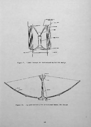
The dual-surface, radial rib design is pratically achievable in diameters up to 50 meters. Packaging of a 50 meter reflector of this design in a single shuttle orbiter bay is readily achievable by segmenting the reflector ribs into 3 sections. The segmented ribs are deployed by articulating mechanisms at each rib segment. Figures 9 and 10 illustrate the stowed and deployed configurations of this design.
9-5
FEED TOWER
Figure 9. Stowed Concept for Articulated Radial Rib Design
Figure 10. Deployed Geometry for Articulated Radial Rib Design
9-6

MULTI-HORN LENS FEED (RETRACTABLE)
DEPLOYABLE/RETRACTABLE WRAP-RIB REFLECTOR
Figure 11. Typical Lockheed Wrap-Rib Antenna: Deployed Configuration
UNFURL/KEFURLDRIVE
FURLED WRAP RIBS/ RF REFLECTIVE MESH PACK
Figure 12. Lockheed Wrap-Rib Antenna: Furling Mechanism
9-7

DIAGONAL
STIDER
HINGE
FULLY DEPLOYED
PACKAGED
Figure 13. General Dynamics Tetrahedron Truss for PETA Antenna
Figure 14. Truss Configuration for General Dynamics PETA Antenna
9-8

example, the minimum weight for the larger size antennas, for a given material, is 6 or 8 bay versions. For this configuration, the basic reflector structure shape is hexagonal rather than circular, so the equivalent reflector diameter is about 101 less than the maximum point-to-point width.
Deployment of the basic tetrahedron is made possible by hinging of the struts at their centers with carpenter tape. This type of hinge provides for zero slop while maintaining with sufficient strain energy to accomplish deployment and an excellent mechanical lock-up in the deployed configuration. Deployment of the composite structure, which consists of a series of tetrahedrons, is essentially equivalent to that of a single bay.
Various materials including aluminum, titanium, and graphite/epoxy have been evaluated for application to the basic truss design. The choice of materials strongly influences the weight, cost, thermal distortion and mechanical packaging efficiency of the antenna. Aluminum tubes provide the lowest cost material, but result in relatively high weight and thermal distortion. Perforated-wall aluminum tubes reduce thermal distortion and weight at some increase in cost. Perforated-wall titanium tubes produce low thermal distortions with weight slightly in excess of perforated aluminum tubes. Graphite/ epoxy tubes produce a very lightweight truss with almost twice the packaging ratio of the perforated aluminum version, because of the smaller tube diameters that can be used with this material.
The RF reflective mesh is supported across each bay by a series of tension ties and a webbing attachment system that interfaces the tension ties with the mesh. The tension ties are attached to standoffs at each spider and span each bay with a simple grid pattern. The webbing system in turn is attached to the tension ties at a number of points to provide a finer grid pattern to which the mesh is attached (Figure 15). The resulting configuration of the mesh is eight flat surface elements, within each bay, that collectively approximate a parabolic surface. For example, in an 8-bay antenna there would be 64 adjustable flat sections across any single diameter of the antenna.
Because of the inherent stiffness of the basic truss structure, attachment of the feed support structure or an ancillary equipment installation may be made at the center, edge, or intermediate locations without significant penalty (Figure 16).
III. Concept Designs for Very Large Mesh Deployable Antenna¥
Promising concepts for large, self- deployable antennas that have been developed to the point of conceptual designs and/or small conceptual mechanical
models include the Harris Corporation Hoop-and-Column Antenna and the LMSC Maypole Antenna.
1. Hoop/Column Design
Summary
The Hoop/Column reflector antenna concept illustrated in Figures 17, 18, and 19 has been developed to the point of a pre liminary design for sizes up to 100 meters. The 1.8 meter demonstration model (Figure 18) was used to verify the basic conceptual design and to aid in development of the kinematics of deployment of the design. The preliminary design has been comple mented with the development of analytical techniques for prediction of antenna performance of these large structures.
Concept Design
The major elements of the Hoop/Column concept are delineated by Figure 17. The fundamental elements of the support structure include the hoop; upper, lower, and center control stringers; and the telescoping mast. The reflector consists of the mesh, mesh shaping ties, secondary drawing surface, and the mesh tensioning stringers. The basic antenna configuration is a type of "Maypole", with a unique technique for contouring the RF reflective mesh.
The hoop's function is to provide a rigid, accurately located structure, to which the reflective surface attaches. It is comprised of 40 rigid sections which articulate at hinges joining adjacent segments. These segments consist of two tubular, graphite fiber members parallel to each other and attached to a long hinge member at each end. These long hinges allow the separation between the tubular members of the hoop segment required by the geometry of the mesh- secondary drawing surface (Figure 21). Torsion springs located in each hinge supply the total energy required to deploy the hoop.
The central column or mast is deploy- able and contains the microwave components and control mechanisms. It consists of tubular graphite/epoxy shell members that nest inside each other when stowed. Aside from housing various components, the mast provides attachment locations for the reflective surface and the stringers.
Five sets of stringers are used on the Hoop/Column concept. Three of these sets are used for hoop deployment and its control; the other two sets are used for mesh shaping. The hoop-control stringers are located at the upper end, the center, and the lower end of the extendible mast; they extend radially outward to their attachment positions at the hinges of the hoop. The upper and lower control stringers accurately position the hoop throughout its deployment (Figure 18).
9-9

S. STRUT —— HSr- —— MESH CREASE LINES
(ELEMENTAL HEXAGONAL FLATS)
Figure 15. Mesh Attachment Configuration for General Dynamics PETA Antenna
Figure 16. Cantilevered Support Configuration of General Dynamics PETA Antenna
9-10

FEED
TELESCOPING FEED SUPPORT
UPPER CONTROL STRINGERS
TELESCOPING MAST (STOWED)CENTER CONTROL
STRINGER
TELESCOPING MAST (EXTENDED)
MESH SHAPING TIES
SECONDARY DRAWING SURFACE
MESH TENSIONING STRINGERS
LOWERCONTROL
STRINGERS
Figure 17. Hoop/Column Concept
9-11

9-12

Figure 19. Deployment Sequence
9-13

The center control stringers are used for rate control during deployment and for moving the hoop joints toward the mast, against their spring forces, during the automated stowing sequence. The remaining two sets of stringers (mesh tensioning stringers) are located just above the lower control stringers and are used to shape the reflective surface into the proper contour. All of these stringers are made of quartz cords for high stiffness and thermal stability.
Preliminary evaluations indicate the mesh tensioning stringers can be effec tively utilized to actively adjust the orbital surface contour of the reflector. The feasibility and technology for such active contour control is being addressed during a current technology program.
The reflective surface as illustrated in Figures 20, 21, and 22 is produced by properly shaping a knitted mesh fabric. The mesh is made of 1.2-mil-diameter, gold-plated molybdenum wire. The mechfe- nism that permits shaping of the mesh consists of numerous radial quartz stringers to which the mesh is directly attached (mesh surface stringers) along with a similar set of stringers (secondary drawing surface stringers) positioned beneath them. Short ties (mesh shaping ties) made of fine wire connect the RF mesh surface stringers to the secondary drawing surface stringers as shown. When the mesh tensioning stringers are tensioned, they in turn tension both the secondary drawing surface stringers and the mesh shaping ties to produce an essentially uniform pressure distribution on the mesh. This pressure distribution allows shaping of the mesh to a good approximation of a parabolic curvature. This configuration for a single gore element is shown in Figure 22. The surface accuracy is affected by the number and spacing of the mesh shaping ties. The greater the number of ties, the greater the surface accuracy.
Two groups of drive mechanisms are used in the Hoop/Column concept. One group, used to extend the mast, consists of one basic set of mechanisms for each section of the telescoping mast. The second group of drive mechanisms is used to adjust the control stringers and consists of motor-driven spools to which the stringers are attached. There are five sets of spools, one for each group of stringers. The spools are used to retract and discharge the stringers during the deployment and stowing sequence and are positioned around the mast in the loca tions described for the stringer attach ments. A torque motor drives each set of spools independently, as required by the specific position and velocity of the hoop joint being controlled.
SURFACE STRINGERS
TYPICAL MESH GORE
Figure 20. Mesh Surface Stringer Configuration
^ SECONDARY DRAWING SURFACE
H TENSIONINO STRINGERS.
Figure 21. Mesh Shaping Technique
SECONDARY DRAWING SURFACE STRIMQERS (QUARTZ)
Figure 22, Mesh Shaping Configuration
9-14

Deployment of the reflector is fully controlled. This prevents damage to the accurately contoured parabolic reflector surface, eliminates the rapid release of a large amount of deployment energy which must be reacted by the spacecraft attitude control system, and allows visual eval uation of the deployment by the shuttle payload specialist.
A unique feature of the design is the ability to restow the reflector. This capability allows maximum utilization of the shuttle capability to retrieve the reflector for ground evaluation and/or for refurbishment for future flights.
2. Lockheed Maypole Antenna
Summary
LMSC developed the maypole concept primarily for self-deployable reflector antennas from 100 m in diameter to 1000 m in diameter. The intended frequency for the smaller sizes is 8.5 GHz, which decreases to 1.0 GHz for the larger sizes. LMSC developed the concept to the point of a preliminary design for the estimation of parameters such as surface accuracy, thermal distortion, mechanical packaging efficiency, weight, cost, and basic dynamic characteristics.
Concept Description
The deployed maypole antenna resembles a "Maypole" or a bicycle wheel. It consists of a long central column and hub, 'a rigid outer rim, and a system of tension cables (spokes) originating from the rim and terminating at both ends of the column. These tensioned spokes locate the rim with respect to the column and stabilize the basic structure. A reflective, paraboloidal mesh cup is suspended at the center of the wheel to form the reflector. The mesh is attached to the parameter of the rim and the hub. The parabolic contouring of the RF reflective mesh is made possible by a series of mesh ribs that are attached to the reflector surface along radial seams. The mesh ribs are tapered, with respect to their attachment to the reflective surface, and terminate into a single cable that is attached to the lower portion of the central column (Figure 23). The proper tension in the mesh rib cable and tension field in the RF mesh result in a parabolic contour of the radial lines of intersection of the two mesh systems. Collectively, these lines of contour approximate a parabolic surface. An increase in the number of ribs improves the surface quality.
The structural design is based on the capability of the outer rim member and the column to withstand the compression loads resulting from the tension loads in the spokes. Very large reflectors use very low tension loads in the spoke ties.. These loads are held at a stable low value by
HOOT TENSION CABLES
TELESCOPING COLUMN
Figure 23. LMSC Maypole Antenna Concept
"load maintainer" mechanisms in series with each spoke. The "sufficiently rigid" outer rim and the center column become feasible because of the low load values in the spokes.
In addition to providing for gradient stabilization of the antenna system against solar pressure, the central column can be used to carry spacecraft control modules, depending on the magnitude of the mass moment-of-inertia ratios. The maypole concept, for very large antennas, is expected to become feasible when near- zero thermal-coefficient-of-expansion materials become available for the mesh, the structural rim, the central column, and the tension tie spokes. Active surface evaluation and control will be required for antennas of this concept when operating in the gigahertz frequency range.
Initial investigation has shown that a 300-m-diameter antenna based on this concept, which operates in the frequency range of 1 to 2 GHz, can be stowed within the cargo volume and weight limits of one Space Shuttle flight.
IV. RF Performance Projections
The designs presented in Section II above have been under development for 10 or more years. While there are substantial differences in the maturity of the three concepts it is probable that all three can be characterized as potentially capable of equivalent performance levels. The designs presented in Section III are conceptual in nature and considerable development will be required to reach a stage from which flight hardware is practical (from performance, cost, and reliability standpoints).
Rather than compare the relative performance measurements of the various designs an attempt is made herein to describe
9-15

presenj and future performance capabilities that either are, or should be, available to system designers. These performance projections are made as a gunction of antenna diameter, rather than antenna type.
The theoretical gain of a circular aperture may be expressed
where
•(¥)G = Gain
CD
D = DiameterX = Wavelength of the incident
radiation.
In theory, therefore, one can achieve any desired gain by making the antenna larger and larger. In practice, however, design and fabrication imperfections create an apparent surface roughness which places an upper bound on the antenna gain. Assuming the 'roughness losses are characterized by the Ruze equation (Reference 5)
(2)
where rj, - Roughness efficiency 9
€ = RMS surface roughnessk = Constant relating focal length/
diameter ratio and illumination taper to the roughness equation (k a 0.9)
then the peak gain of a roughness limited antenna is expressed by
-1(3)
and occurs when
DID
Equation 3 indicates that antenna gain is limited by the diameter-to-roughne£S ratio D/f. Figure 24 presents the D/£ ratio as a function of antenna diameter for the three cases of:
• Present state-of-the-art with passive surface control.
• Achievable state-of-the-art with passive surface control,
• Potential state-of-the-art with active surface control.
Passive surface control implies the antenna contour is established on earth during fabrication and is not adjustable in the orbital environment. Active control implies the capability to actively adjust the contour in the
5 X 10 "
4 X 10 "
ACTIVE SURFACE CONTROL (PROJECTED FUTURE TECHNOLOGY)
PASSIVE SURFACE CONTROL (PROJECTED UPPER BOUND' FOR PASSIVE TECHNIQUES)
PASSIVE SURFACE CONTROL CURRENT TECHNOLOGY
30 100 3dO
ANTENNA DIAMETER IN METERS
Figure 24. Present and Projected Diameter to Surface Roughness for Mesh Deployable Antennas
orbital environment. All three curves show a noticeable degradation at small dimaeters. This effect is created by manufacturing uncertainties inherent in the fabrication of mesh reflectors. These errors are linear in nature and tend to produce a lower bound on the RMS surface roughness. As the antenna diameter increases the linear manufacturing errors become smaller and smaller contributors to the total system error. At larger diameters, the manufacturing errors become angular in nature and are more associated with the antenna structural elements and manufacturing tooling rather than the mesh and mesh contouring system. The angular limitations for systems and techniques currently in use at Harris are on the order of 50^ radians.
The TDRSS antenna, currently in production at Harris, exhibits between 0.4mm and 0.5mm of manufacturing uncertainty. Evaluations have shown that a limiting value of 0.2mm is achievable. The two upper curves in Figure 24 utilize this 0.2mm value for linear uncertainty. The angular uncertainties associated with the upper curves are 25jLf radian and 16.7/1 radian. The 2Sfi radian value is based on evaluation of potential improvements to existing equipment. The 16.7/1 radian for an actively controlled surface is consistent with the angular accuracy of currently available angular transducers.
Utilizing the D/i" values shown in Figure 24 the maximum roughness limited gain as a function of diameter is shownin Figure 25. The information contained
9-16

D/F (PEAK GAIN)
X 60,000 (80.1 dB)
\40,000 (76.6 dB)
20,000 (70.6 dB)
10,000 (64.5 dB)
1,000
D A
Figure 25. Maximum Roughness Limited Gain for Mesh Deployable Antennas
in Figures 24 and 25 is combined to yield an operating envelope for mesh deployable antennas as shown in Figure 26. Figure 26 points out an additional performance limitation, that of the mesh. Harris has conducted measurements on the gold- plated molybdenum mesh presently used for antenna surfaces at frequencies ranging from 400 MHz to 60 GHz. These tests indicate that for the present state-of-the-art mesh may be knitted with sufficient density to support frequencies up to 30 GHz with losses on the order of 0.25 dB. At frequencies above 30 GHz the mesh exhibits significant polarization effects which need further evaluation. A probable maximum frequency bound for mesh reflectors is estimates to be 60 GHz.
PERFORMANCE BOUNDS FOR MESH
1. CURRENT PASSIVE TECHNOLOGY2. PROJECTED PASSIVE TECHNOLOGY3. PROJECTED ACTIVE TECHNOLOGY
100-
, 10-
10 30 100
ANTENNA DIAMETER IN METERS
300
Figure 26. Operating Envelope forMesh Deployable Antennas
Other antenna losses not accounted for in Figure 26 include blockage loss, losses due to the feed illumination (spillover and amplitude taper) and ohmic losses of the feed system. In general, these losses range from 1.5 dB for a very efficient antenna to 2.5 dB for a more typical antenna.
It should also be pointed out that the performance bounds illustrated in Figure 26 are for the peak gain points of the roughness limits. Systems operating near these performance bounds are subjected to a substantial roughness loss which reaches a value of 4.343 dB at the bound itself. For cases where aperture efficiency is of great importance (e.g. radiometers) the operating point should be moved 5 dB nearer the origin with a subsequent 5 dB loss in peak gain. However the resulting roughness loss is decreased to approximately 0.6 dB.
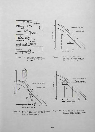
Having established the present and projected future performance bounds of mesh deployable antennas it is of interest to follow with an evaluation of thier potential utility to projected future missions. Reference 6 provides an excellent summary of such missions. The user offices proposing future missions, at this time, include the NASA Office of Space Science (OSS), Office of Space and Terrestrial Applications (OSTA) and the Office of Aeronautics and Space Technology (OAST). Figure 27 represents a summary of potential missions utilizing large antennas for the 1985 to 2000 time period. Table 1 identifies potential missions from the OAST mission model.
In order to focus the development of technology for proposed future missions the Large Space Systems Technology (LSST) Office developed the concept of "focus missions". The focus missions approach is to broaden the narrow, individual mission requirements into a broader matrix of requirements and thereby enhance the probability of developing concepts of broad applicability as opposed to a concept that satisfies only a particular set of requirements. The LSST focus missions were initiated by selecting characteristic classes of missions whose potential performance satisfy a large number of specific missions presently identified. Tables -2 and 3 identify the near and far term focus missions presently selected.
Figure 26 is reproduced in Figure 28 with the NASA OAST mission candidates from Table 1 superimposed. Similarly Figures 29 and 30 have the near-term and far-term mission candidates superimposed. These figures illustrate that the mesh deployable antenna technology is capable of satisfying a large majority of the candidate missions.
9-17
45 m 30 m 60 m A APLATFORM A
PLATFORM (GEO) MARS RECEIVING 30m (MIDLATITUDE) 60m LABORATORY A A (LEO)
PLATFORM (MIDLATITUDE)
PLATFORM(MIDLATITUDE) 30m
APLATFORM (POLAR)
SCIENCE
60m A
VLDI DISH (HEO) 1000
>300mA
SETI (GEO)
GRAVITY WAVE/ PINHOLE SATELLITE (HEO)__________
30m A
PLATFORM (MIDLATITUDE)
APPLICATIONS
46m A
PLATFORMS (POLAR)
A(SUN SYNCHRO)
A(MIDLATITUDE)45m >45m 100m A A A COMMUNICATIONS
NARROWBAND* NARROWBAND* PLATFORM (GEO) COMM. TECH COMMUNICATIONS ANTENNA (LEO) SATELLITE (GEO) ___*MAY USE SAME ANTENNA
TRACKING200m
AODSRS (GEO)
NEAR TERM | MID TERM I 1985
10 30 100
ANTENNA DIAMETER IN METERS
Figure 27. NASA OAST MissionsInvolving Large Space Systems
Figure 29. Mesh Deployable AntennasSatisfy the Near-Term LSST Focus Mission Requirements
3 10 30 100
ANTENNA DIAMETER IN METERS
3 10 30 100
ANTENNA DIAMETER IN METERS
Figure 28, Mesh Deployable Antennas Satisfy Most of the OAST Candidate Mission Requirements
Figure 30. Mesh Deployable AntennasSatisfy the Far-Term Focus Mission Requirements
9-18

Table 1. NASA OAST Antenna Reflector Mission Candidates
cpCD
OFFICE
OSTA(Radiometers )
OSS
OSTA (Communicati ons )
1
2
10
3
4
5
6
7
8
9
APPLICATION
0.1-km radio meter
500-km resolution cl imate
OSTA experimental radiometer
Submi 1 1 imeter
VLBI
SETI
Deep Space Relay ODSRS
Mobi 1 e
PBS/TV
20-30 OSTA
Personal
FREQUENCY, GHz
1-20
1-20
1-20
300-1000
1-22
1
30
1
5
20-30
5-20
DIAMETER, m
50-1000
1
30
10-24
30-65
100
30
30-50
50
4
70
BEAMS
/vlOOO
1-100
100-1000
1-100
1-100
1
1
100
1000
10
10000
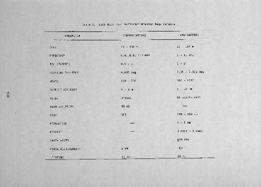
Table 2. LSST Near Term Reflector Mission Requirements
ro o
PARAMETER
SIZE
FREQUENCY
f/d (PARENT)
POINTING ACCURACY
BEAMS
SURFACE ACCURACY
FEEDS
BEAM ISOLATION
ORBIT
RESOLUTION
REVISIT
SWATH WIDTH
POWER REQUIREMENTS
LIFETIME
COMMUNICATIONS RADIOMETERS
30 - 100 m 10 - 100 m
0.4, 0.8, 2.5 GHz 1 - 11 GHz
0.5-1 1-2
0.035 deg 0.05 - 0.025 deg
100 - 200 300 - 1000
4 - 8 mm 3 - 10 mm
Offset Offset/On Axis
30 dB ——
GEO 300 - 600 km
—— 1 - 5 km
—— 3 days - 1 week
—— . ±30 deg
5 kW TBD
10 Yr 10 Yr
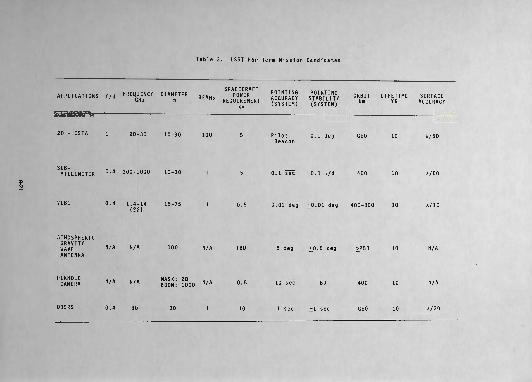
Table 3. LSST Far Term Mission Candidates
FRFmiFwrv niAMFTFD $ ? ̂ m jCrRDA F T POINTING POINTING APPLICATIONS f/d F^QUENCY DIAMETER BEAM$ POWER ACCURACY STABILITY GHz m REQUIREMENT (SYSTEM) (SYSTEM)
20 - OSTA 1 20-30 10-30 100 5 Pilot 0.1 deg Beacon
SUB MILLIMETER °' 4 300-1000 10-30 1 5 0.1 "sec" 0.1 \/d
VLBI 0.4 1.4-14 15-75 1 0.5 0.01 deg +0.01 deg (22)
ATMOSPHERIC0 n A U T TV
WAVE N/A N/A 10 ° N/A TBD 5 deg i°* 5 degANTENNA
PINHOLE MASK: 20 /. Q . . Q — - TBD CAMERA N/A N/A BOOM: 1000 N/A °* 5 1U sec BU
ORBIT LIFETIME SURFACE km YR ACCURACY
GEO 10 A/50
400 10 A/50
400-800 10 A/10
>250 10 N/A
400 10 N/A
ODSRS 0.4 30 30 10 1 sec +1 sec GEO 10 A/30

References
1. Freeland, R. E., Industry Capability for Large Space Antenna Structures, 25 May, 1978, JPL.
2. Tankersley, B. C. and Bartlett, H. E., Tracking and Data Relay Satellite Single Access Deployable Antenna, NIC Conference Record, 1977.
3. Campbell, G. K. C., and Damonte, J. B., Large Furlable Antenna Study, LMSC/D384797, 20 January, 1975.
4. Brewer, C. C. , and Wade, 0., Parabolic Expandable Truss Antenna (PETA), General Dynamics, Convair.
5. Ruze, J., "Antenna Tolerance Theory - A Reivew", Proc. IEEE, J.4 No. 4, April 1966, pp. 633-640.
6. Campbell, T. G. and Freeland, R. E., "Deployable Antenna Technology Developmentfor the Large Space Systems Technology Program", AIAA/NASA Conference on Advanced Technology for Future Space Systems, 8-10 May, 1979.
9-22


![A Deployable Quasi-Yagi Monopole Antenna Using Three ...[20]. Although a tetrahedron Yagi–Uda origami antenna has been reported in [21], the design is very large and hence, its transportation](https://static.fdocuments.in/doc/165x107/60999ddcca50ad59d27548e6/a-deployable-quasi-yagi-monopole-antenna-using-three-20-although-a-tetrahedron.jpg)