
Large Structures CFD Simulations For Water &...
26
Large Structures CFD Simulations For Water & Wastewater Treatment Plants P. Fonseca, N. Marques, J. Azevedo, V. Rodrigues, M. Toïgo
-
Upload
nguyenliem -
Category
Documents
-
view
226 -
download
0
Transcript of Large Structures CFD Simulations For Water &...

Large Structures CFD Simulations
For Water & Wastewater Treatment Plants
P. Fonseca, N. Marques, J. Azevedo, V. Rodrigues, M. Toïgo

Large Structures CFD Simulations For Water & Wastewater Treatment Plants - STAR Global Conference 2014
Outline
1. Introduction 2. Problem Overview 3. CFD modelling Strategy 4. Examples:
1. Channel distribution 2. Circular distribution chamber 3. Non-circular distribution chamber 4. Pressure system distribution 5. CFD and 1D analysis
5. STAR-CCM+ assessment 6. Conclusions

Large Structures CFD Simulations For Water & Wastewater Treatment Plants - STAR Global Conference 2014
Introduction
The water treatment plant conception can be classified in the process industry. The treatments are of the physical and chemical type (filters, settlers, coagulation, biological tanks, etc).
Most of the water treatment processes are standardized. as a result of many years of accumulated experience.
CFD has for long been used on the R&D of water treatment processes. The use of CFD on every day design is less common on the market.

Large Structures CFD Simulations For Water & Wastewater Treatment Plants - STAR Global Conference 2014
Problem Overview
The focus here will be exclusively on these case-by-case applications and their relevance on the design of each treatment plant (i.e., not on R&D cases). All examples are the result of the close collaboration of a water treatment market leader company with a CFD specialist company. All structures are large (up to dozens of meters), but subject to the impact of small details (centimeters: orifices, distribution weirs, small baffles, etc.) and with conclusions sensible to a water surface definition (on the order of the millimeters). Complexity and optimization needs make the case for everyday use of the CFD. Most thumb rules no longer belong to the current highly competitive market.
Large Structures CFD Simulations For Water & Wastewater Treatment Plants - STAR Global Conference 2014
CFD Modelling strategy
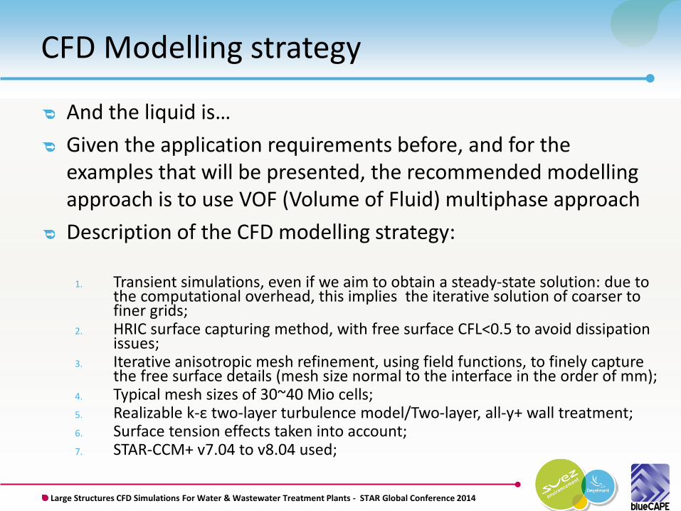
And the liquid is… Given the application requirements before, and for the examples that will be presented, the recommended modelling approach is to use VOF (Volume of Fluid) multiphase approach Description of the CFD modelling strategy:
1. Transient simulations, even if we aim to obtain a steady-state solution: due to
the computational overhead, this implies the iterative solution of coarser to finer grids;
2. HRIC surface capturing method, with free surface CFL<0.5 to avoid dissipation issues;
3. Iterative anisotropic mesh refinement, using field functions, to finely capture the free surface details (mesh size normal to the interface in the order of mm);
4. Typical mesh sizes of 30~40 Mio cells; 5. Realizable k-ε two-layer turbulence model/Two-layer, all-y+ wall treatment; 6. Surface tension effects taken into account; 7. STAR-CCM+ v7.04 to v8.04 used;

Large Structures CFD Simulations For Water & Wastewater Treatment Plants - STAR Global Conference 2014
Examples : Distribution structures Split the flow rate between parallel lines of treatment. Typically made out of concrete, they can go up to several dozens of meters in diameter or length. Influenced by the process designs being applied upstream and downstream. The diversity of possibilities makes these structures very prone to case by case design. Static structures are preferred. Layout arranges go from circular to linear. Flow rate outlet is generally performed by free fall sharp crest weir: The weir outlet structure brings the independency of the distribution from the downstream system, The weir outlet is highly sensible to flow behavior.
Three different cases are presented: channel distribution structure, and the cross validation of reduced complexity methods, circular distribution chamber, and its comparison with general rules of conception
guidelines,
rectangular distribution chamber, with a non typical improved conception.

Large Structures CFD Simulations For Water & Wastewater Treatment Plants - STAR Global Conference 2014
Channel distribution 1/3 In its simplest form, distributes water through lateral weirs, placed on one or both sides of the channel. The example is based on the simplest form: no upstream orifice chambers, etc.
Objective of the example: simple comparison between the typical dimensioning methods and the CFD modeling.
Operating Conditions:
CASE A: Peak flow rate inlet = 4.936 m³/s CASE B: Peak flow rate inlet A= 6.477 m³/s Water properties: ρ = 999 kg/m³; μ = 1,15x10⁻³ Pa-s
Simulation Conditions: Trimmed mesh with a prismatic cell sublayer at wall boundaries; Final mesh with 13 855 819 cells Inlet as "Mass flow" and outlet as "Pressure outlet"

Large Structures CFD Simulations For Water & Wastewater Treatment Plants - STAR Global Conference 2014
Channel distribution 2/3
Velocity Magnitude
Water Surface Elevation

Large Structures CFD Simulations For Water & Wastewater Treatment Plants - STAR Global Conference 2014
Channel distribution 3/3
1D simulation based on proven methodology and on formulation of common use (conservation of energy, Manning-Strickler, DeMarchi, etc.).
CFD results 1D simulation
Conclusion 1: Extremely good agreement between the 1D and the CFD Difference between methods: < 0.5% of flow rate distribution
Conclusion 2: CFD is of no use! Well… for the simplest of the cases. Most real conceptions are not 1D reducible.

Large Structures CFD Simulations For Water & Wastewater Treatment Plants - STAR Global Conference 2014
Circular distribution chamber 1/3
Cost constraints force very small overall diameters and little to no re-alignment height for the upwards bent stream. The inlet jet has a natural tendency to hit the water surface deviated from the center, i.e. closer to some particular weir. Being a weir a very sensible structure, this can originate a bad distribution.
“smoking pipe” kind of geometry: arriving from the bottom, water is redirected to the surface, distributes through the peripheral weirs (the example being presented is based on the simplest form:
no inner baffles, etc.) very sensible design. e.g. the 90º bend of the streamlines at the inlet
Operating Conditions: Flow rate= 18.065,45 m³/h Water properties: ρ = 999 kg/m³ μ = 1,25x10⁻³ Pa-s
Simulation Conditions: Trimmed mesh with a prismatic cell sublayer at wall boundaries; Final mesh with 35 412781 cells; Inlet as "Mass flow" and outlet as "Pressure outlet“.
Objective of the example: Verify if solution are possible well beyond the general rules of thumb

Large Structures CFD Simulations For Water & Wastewater Treatment Plants - STAR Global Conference 2014
Circular distribution chamber 2/3
General rules of thumb that could be applied on these particular designs: Relation of jet velocity (kinetic energy) vs weir water height or overall
chamber diameter; minimum alignment vertical length; etc.
A curling flow is clear on the inner chamber
The "secondary" phenomena going on the 3D domain can be quickly appreciated. These render all the typical rules far from optimum.

Large Structures CFD Simulations For Water & Wastewater Treatment Plants - STAR Global Conference 2014
Circular distribution chamber 3/3
This is only a particular case of the circular distribution chamber domain; Some of this domain can actually be standardized.
Conclusion 1: Optimum relation between inlet pipe and the first chamber diameter, This un-strengthens the jet hitting the surface, greatly improving distribution
Conclusion 2: Either for optimization purposes or due to the huge possible variation of the main parameters (including non aligned inlet layouts, etc), case by case analysis is a constant need. CFD, as a general design tool on the day to day work of the engineer, becomes an advantage.

Large Structures CFD Simulations For Water & Wastewater Treatment Plants - STAR Global Conference 2014
Non circular distribution chamber 1/3 “smoking pipe” geometry short length chamber a wall effect near the two weirs in front of the entry. Helping the direction change with guiding vanes delicate on bad fluid quality processes
Objective of the example: test the most simplified of the guiding vanes a simple entry baffle that opens the jet depth, dividing it into two vertical ones, mastering the wall
effect.
Operating Conditions: Flow rate= 3,76 m³/s Water properties: ρ = 998 kg/m³ μ = 1,31x10⁻³ Pa-s
Simulation Conditions: Trimmed mesh with a prismatic cell sublayer at wall boundaries Final mesh with 11 514 025 cells Inlet as "Mass flow" and outlet as "Pressure outlet“.
The distribution quality is possible to estimate without the entry baffle. The 3D effect of the baffle obliges to a CFD simulation

Large Structures CFD Simulations For Water & Wastewater Treatment Plants - STAR Global Conference 2014
Non circular distribution chamber 2/3

Large Structures CFD Simulations For Water & Wastewater Treatment Plants - STAR Global Conference 2014
Non circular distribution chamber 3/3
Conclusions: It is visible the in-depth distribution created by the baffle. The wall effect (coanda) is only of 3 cm, having a small impact on the distribution (≈1%)

Large Structures CFD Simulations For Water & Wastewater Treatment Plants - STAR Global Conference 2014
Pressure system distribution case 1/2 Not all distribution systems are sensible, or deserve modeling The example shows: four parallel pressure inline UV chambers, in non symetrical arrangement Low approaching velocities, and “high” head loss of the chambers => distribution is perfect
Objective of the example: to prove that what is good by design needs no modeling (CFD as a marketing tool)
Operating Conditions: Scenario 1 Flow rate at Inlet Q= 3500 m³/h Flow rate at Pump Q = 0 m³/h
Scenario 2 Flow rate at Inlet Q= 3500 m³/h Flow rate at Pump Q = 640 m³/h Water properties: ρ = 998 kg/m³;
μ = 1.25e-3 Pa-s
Simulation Conditions: Trimmed mesh with a prismatic cell sublayer at wall boundaries Final mesh with 45 623 017 cells

Large Structures CFD Simulations For Water & Wastewater Treatment Plants - STAR Global Conference 2014
Pressure system distribution case 2/2
Conclusions: Distribution quality is very good, as estimated. Good images are sometimes relevant, for multiple reasons

Large Structures CFD Simulations For Water & Wastewater Treatment Plants - STAR Global Conference 2014
The CFD when head loss uncertainty is high 1/2
Plant refurbishment (more and more common) or other constraints create case by case conceptions deviated from typical geometries Bibliographical head loss coefficients lose applicability, and uncertainty grows Objective of the example: to verify the head loss of an open channel system, where multiple cross section conversions and bends exist, on a short distance.
Operating Conditions: Flow rate= 10 to 20 m³/s Water properties: ρ = 998 kg/m³ μ = 1,31x10⁻³ Pa-s
Simulation Conditions: Trimmed mesh with a prismatic cell sublayer at wall boundaries Final mesh with 30 883 326 cells Inlet as "Mass flow" and outlet as "Pressure outlet“.

Large Structures CFD Simulations For Water & Wastewater Treatment Plants - STAR Global Conference 2014
Water level referenced to geodesic level (F).
Total head for the defined sections.
The CFD when head loss uncertainty is high 2/2
Conclusions: Head losses calculated by simplified methods based on standard bibliographic sources can be deviated by up to one order of magnitude.

Large Structures CFD Simulations For Water & Wastewater Treatment Plants - STAR Global Conference 2014
CFD: foundation for common 1D simulations 1/2
Inlet, outlet, and, sometimes the process treatments themselves, have long “1D” extentions (imagine the city domain). The models are hugely time dependent, making the 1D a perfect option for speed.
Objective of the example: present a simple open channel flow regulation valve head loss simulation, as a calibration input of a 1D model
Operating Conditions:
Water properties: ρ = 999 kg/m³ μ = 1,15x10⁻³ Pa-s
- Flow rate (Q): Case A = 5 m³/s Case B = 10 m³/s Case C = 15 m³/s Case D = 20 m³/s
- Free Surface Height (H): 3.0 m (case A and B) 3.5 m 4.0 m 4.5 m 5.0 m
- Valve Position (G): 10% 20% 30% 50% 70% 90% 110%

Large Structures CFD Simulations For Water & Wastewater Treatment Plants - STAR Global Conference 2014
CFD: foundation for common 1D simulations 2/2
Batch simulation of 120 design points

Large Structures CFD Simulations For Water & Wastewater Treatment Plants - STAR Global Conference 2014
STAR-CCM+ assessment: our experience
CAD treatment and manipulation Clean import of CAD models means no feedback loop necessary; 3D-CAD tools allow fast modification or geometry generation from 2D schematics;
Meshing tool Fast mesh generation times, with resulting high quality meshes; In-simulation anisotropic mesh refinement considerably speeds up turnaround time
and allows detailed physical insight without too much computational burden.

Large Structures CFD Simulations For Water & Wastewater Treatment Plants - STAR Global Conference 2014
STAR-CCM+ assessment: our experience
Physical Setup Wide range of material properties models , necessary to deal with different type of
effluents and wastewater; VOF model Interface tracking model HRIC allows very good results and detailed analysis; Extensions of the model to include phenomena as gas dissolution are important;
Good Scalability Large range of problems means simulations done from workstations to large clusters
Confidence Validated against analytical, simplified 0D models for simple cases and against real
operational data for large structures
Water cascade Metal weir to promote aeration
Aeration region
Details matter!!

Large Structures CFD Simulations For Water & Wastewater Treatment Plants - STAR Global Conference 2014
STAR-CCM+ assessment: features request/whislist
Steady State VOF improvements: Hard to achieve convergence (as in stabilized free surface elevation); “Wrinkling” of free surface, even using angle factor and sharpening factor
corrections in some cases; Presence of parasitic currents hard to eliminate → still to test new interface
Momentum Dissipation Model of v8.06
2D VOF improvements: Numerical robustness issues; Important for some parametric studies (see above valve simulations);

Large Structures CFD Simulations For Water & Wastewater Treatment Plants - STAR Global Conference 2014
Business culture and workflow
Very close collaboration between the two partners Water treatment hydraulic expertise ↔ computational fluid dynamics
expertise
Adapted methods of work to match with both business needs Reciprocal training for deeper understanding
Long term project

Large Structures CFD Simulations For Water & Wastewater Treatment Plants - STAR Global Conference 2014
Conclusions
The collaboration allowed the acquisition and continued development of competences in multiphase modelling;
Optimized workflow of STAR-CCM+ increased significantly the simulation output;
Continuous development of multiphase models by CD-adapco opens up new simulation venues.
Expertise on both domains (core business and CFD) is extremely important;
Day by day use, on completely common subjects, is a reality; Extension of analyzed problems in the works, including
Eulerian Multiphase (EMP) simulations to determine gas bubble sizes in WTUs and sand filters optimization;


