Large Size 3 Port Solenoid Valve VP3145/3165/3185...
10
1 (IN) (OUT) 2 3 (EXH) (OUT) 2 1 (IN) 3 (EXH) (OUT) 2 1 (IN) 3 (EXH) X (PA) (OUT) 2 1 (IN) 3 (EXH) X (PA) N.C. N.O. N.C. N.O. Note) The pilot valve assembly shown above includes the function plate and gasket. Body ported 5 Body type N.C. (Normally closed) A N.O. (Normally open) B Body size Port size (IN, OUT port) Symbol 03 Port size Rc (Nominal size) 04 VP3145 1 Number of solenoids Single Nil Standard (Internal pilot) 1 External pilot Type of actuation Pilot option Valve option Nil For general V For vacuum/low pressure ∗ Semi-standard For other rated voltages, please consult with SMC. 06 10 12 14 20 04 4 5 1 VP3 A G 1 VP3165 VP3185 VP series 3 port solenoid valve Electrical entry Coil rated voltage 00 VT3113 G 1 Large flow capacity, small exhaust resistance (Refer to “Flow Rate Characteristic” table.) Easy conversion to N.C. or N.O. Function plate makes it possible to use as a N.C. or N.O. valve with the port unchanged. Possible to use in vacuum or under low pressures Vacuum: Up to 101.2 kPa Low pressure: 0 to 0.2 MPa Free mounting orientation Note) N.O. valve operates properly only when appropriate pressure is applied to the pilot. Symbol Internal pilot <Standard> External pilot Made to Order (Refer to pages 1313 to 1315 for details.) 1 4 6 8 1 2 1 2 1 (10A) 3 8 (15A) 1 2 (20A) 3 4 (25A) 1 (50A) 2 (32A) 1 4 1 (40A) 1 2 1 100 VAC, 50/60 Hz 200 VAC, 50/60 Hz 110 VAC, 50/60 Hz 220 VAC, 50/60 Hz 24 VDC 12 VDC 240 VAC, 50/60 Hz 1 2 3 ∗ 4 ∗ 5 6 ∗ 7 ∗ ∗ Semi-standard For other rated voltages, please consult with SMC. Coil rated voltage 100 VAC, 50/60 Hz 200 VAC, 50/60 Hz 110 VAC, 50/60 Hz 220 VAC, 50/60 Hz 24 VDC 12 VDC 240 VAC, 50/60 Hz 1 2 3 ∗ 4 ∗ 5 6 ∗ 7 ∗ TL ∗ D T G TS ∗ TZ ∗ DL ∗ DS ∗ DZ ∗ Grommet Conduit terminal DIN terminal Conduit terminal with indicator light Conduit terminal with surge voltage suppressor Conduit terminal with light/surge voltage suppressor DIN terminal with indicator light DIN terminal with surge voltage suppressor DIN terminal with light/surge voltage suppressor ∗ Semi-standard CE-compliant Electrical entry Rc Nil G F NPT N NPTF T Thread type CE-compliant Q CE-compliant Note) Nil — Note) Electrical entry: D/DL/DS/DZ only CE-compliant Q CE-compliant Note) Nil — TL ∗ D T G TS ∗ TZ ∗ DL ∗ DS ∗ DZ ∗ Grommet Conduit terminal DIN terminal Conduit terminal with indicator light Conduit terminal with surge voltage suppressor Conduit terminal with light/surge voltage suppressor DIN terminal with indicator light DIN terminal with surge voltage suppressor DIN terminal with light/surge voltage suppressor ∗ Semi-standard CE-compliant Note) Electrical entry: D/DL/DS/DZ only How to Order Pilot Valve Assembly How to Order [Option] Large Size 3 Port Solenoid Valve VP3145/3165/3185 Series Rubber Seal Note) CE-compliant: D/DL/DS/DZ only (Electrical entry) 1307 SYJ VQZ VP VG VP3
Transcript of Large Size 3 Port Solenoid Valve VP3145/3165/3185...

1(IN)
(OUT)2
3(EXH)
(OUT)2
1(IN)
3(EXH)
(OUT)2
1(IN)
3(EXH)
X(PA)
(OUT)2
1(IN)
3(EXH)
X(PA)
N.C. N.O.
N.C. N.O.
Note) The pilot valve assembly shown above includes the function plate and gasket.
Body ported5Body type
N.C. (Normally closed)AN.O. (Normally open)B
Body size
Port size (IN, OUT port)
Symbol
03
Port sizeRc (Nominal size)
04
VP3145
1
Number ofsolenoids
Single
Nil Standard (Internal pilot)1 External pilot
Type of actuation
Pilot option
Valve optionNil For generalV For vacuum/low pressure
∗ Semi-standardFor other rated voltages, please consult with SMC.
0610121420
044 51VP3 AG1
VP3165 VP3185
VP series 3 portsolenoid valve
Electrical entry
Coil rated voltage
00VT3113 G1
Large flow capacity, small exhaust resistance(Refer to “Flow Rate Characteristic” table.)
Easy conversion to N.C. or N.O.Function plate makes it possible to use as a N.C. or N.O. valve with the port unchanged.
Possible to use in vacuum or under low pressuresVacuum: Up to 101.2 kPaLow pressure: 0 to 0.2 MPa
Free mounting orientation
Note) N.O. valve operates properly only when appropriate pressure is applied to the pilot.
SymbolInternal pilot<Standard>
External pilot
Made to Order(Refer to pages 1313 to 1315 for details.)
1
468 1 2
1 2
1
(10A)3 8
(15A)1 2
(20A)3 4
(25A)1
(50A)2
(32A)1 41
(40A)1 21
100 VAC, 50/60 Hz200 VAC, 50/60 Hz110 VAC, 50/60 Hz220 VAC, 50/60 Hz24 VDC12 VDC
240 VAC, 50/60 Hz
123∗
4∗
56∗
7∗
∗ Semi-standardFor other rated voltages, please consult with SMC.
Coil rated voltage100 VAC, 50/60 Hz200 VAC, 50/60 Hz110 VAC, 50/60 Hz220 VAC, 50/60 Hz24 VDC12 VDC
240 VAC, 50/60 Hz
123∗
4∗
56∗
7∗
TL∗DTG
TS∗
TZ∗
DL∗
DS∗
DZ∗
GrommetConduit terminal
DIN terminalConduit terminal with indicator light Conduit terminal with surge voltage suppressorConduit terminal with light/surge voltage suppressor
DIN terminal with indicator lightDIN terminal with surge voltage suppressorDIN terminal with light/surge voltage suppressor
∗ Semi-standard
CE-compliant
Electrical entry
RcNilGF
NPTNNPTFT
Thread type
CE-compliant
Q CE-compliant Note)
Nil —
Note) Electrical entry: D/DL/DS/DZ only
CE-compliant
Q CE-compliant Note)
Nil —TL∗DTG
TS∗
TZ∗
DL∗
DS∗
DZ∗
GrommetConduit terminal
DIN terminalConduit terminal with indicator light Conduit terminal with surge voltage suppressorConduit terminal with light/surge voltage suppressor
DIN terminal with indicator lightDIN terminal with surge voltage suppressorDIN terminal with light/surge voltage suppressor
∗ Semi-standard
CE-compliant
Note) Electrical entry: D/DL/DS/DZ only
How to Order Pilot Valve Assembly
How to Order
[Option]
Large Size 3 Port Solenoid Valve
VP3145/3165/3185 SeriesRubber Seal
Note) CE-compliant: D/DL/DS/DZ only (Electrical entry)
1307
SYJ
VQZ
VP
VG
VP3VP3
Type of actuation
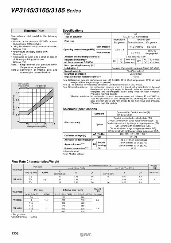
Ambient and fluid temperature (°C)Response time (ms) (1) (at the pressure of 0.5 MPa)
Lubrication (2)
Manual override
Impact/Vibration resistance (m/s2) (3)
N.C. or N.O. (Convertible)
0 (No freezing) to 60
Fluid Air
Pilot typeInternal pilotFor general
Main pressure
Pilot pressure0.2 to 0.8
External pilot
Operating pressure range (MPa)
For vacuum/low pressure For general
Required (Equivalent to turbine oil Class1 ISO VG32)Max. operating frequency (Hz) 3
Yes (Non-locking)Mounting orientation Unrestricted
150/50
Specifications
Valve model
VP3145
Port size
3 81 23 4
3 4
Weight ∗(kg)
1.5
GrommetC[dm3/(s·bar)] b Cv
C[dm3/(s·bar)] b Cv
19 0.43 5.5 18 0.47 5.423 0.32 6.2 21 0.39 5.828 0.36 7.6 26 0.35 7.0
1 2 (IN OUT) 2 3 (OUT EXH)Flow rate characteristics
1(IN), 2(OUT) 3(EXH)
Valve model
VP3165
VP3185
Port size Effective area (mm2)
1 4
Weight ∗(kg)
2.0
2.8
Grommet1 (IN), 2 (OUT) 3(EXH) 1 2 (IN OUT)230280310570650650
2 3 (OUT EXH)280310330650670670
1
2
1 4
3 4
11 411 21
1
2
∗ For grommetConduit terminal··· +0.2 kg
Flow Rate Characteristics/Weight
Electrical entry
Coil rated voltage (V)
Allowable voltage fluctuationDC
DC
AC ( Hz)
Standard
Option
50 60
Solenoid Specifications
∗ Semi-standardNote) At rated voltage
Use external pilot model in the following cases.• Vacuum or low pressure (0.2 MPa or less):
Vacuum/Low pressure type• Using the valve with supply port external throttle:
General type• Air pressure of supply port is slow:
General type• Resistance in outlet side is small in case of
air blowing or filling an air tank:General type
Note 1) Keep external pilot pressure within the pressure range below.
Note 2) Conversion of internal pilot and external pilot can not be done.
External Pilot
Main pressure (MPa)
For vacuum/low pressure For general
Pilo
t pre
ssur
e (M
Pa)
–101.2 kPa to 0.2 0.2 to 0.8
0.2 to 0.3Refer to
the graph left.
OFFAC 30 or less
ONAC 30 or less
DC 30 or lessDC 40 or less
Note 1) Based on dynamic performance test, JIS B 8419: 2010. (Coil temperature: 20°C, at rated voltage, without surge voltage suppressor)
Note 2) This solenoid valve requires lubrication. Use turbine oil Class 1 (ISO VG32).Note 3) Impact resistance: No malfunction occurred when it is tested with a drop tester in the axial
direction and at the right angles to the main valve and armature in both energized and de-energized states every once for each condition. (Values at the initial period)
Vibration resistance: No malfunction occurred in a one-sweep test between 45 and 1000 Hz. Test was performed at both energized and de-energized states in the axial direction and at the right angles to the main valve and armature. (Values at the initial period)
ACInrushHolding
Grommet (G), Conduit terminal (T)DIN terminal (D)
Conduit terminal with indicator light (TL),Conduit terminal with surge voltage suppressor (TS),
Conduit terminal with light/surge voltage suppressor (TZ),DIN terminal with indicator light (DL),
DIN terminal with surge voltage suppressor (DS),DIN terminal with light/surge voltage suppressor (DZ)
100, 200, 110 ∗, 220 ∗, 240 ∗
12 ∗, 24–15 to +10% of rated voltage73 VA (50 Hz), 58 VA (60 Hz)28 VA (50 Hz), 17 VA (60 Hz)
12 W
Apparent power Note)
Power consumption Note)
VP3145/3165/3185 Series
1308

As in the figure below, this pilot-operated solenoid valve consists of a compact 3 port solenoid valve as the pilot valve and a large 3 port valve as the main valve. The pilot valve controls opening and closing the main valve. N.C. or N.O. function conversion can be done by switching the pilot passage.
Note) Pilot valve and body are shown in a different direction from the actual product in order to show the construction and air passage.
Piping (Vacuum Use) N.C./N.O. Conversion1. Piping in general:
EXH port =
OUT port =
IN port =
2. Following the above piping, vacuum passage is switched between OUT and EXH, therefore, N.C./N.O. indication on the function plate and switching of the vacuum passage are reversed; N.C. (Normally closed) in vacuum passage are reversed:
“N.C.” indicated on the plate N.O. in vacuum passage
(Normally open) “N.O.” indicated on the plate N.C. in vacuum passage
(Normally closed)
(Suction side)Vacuum pump/Blower Tank/Vacuum pad
(Load side)
Plug (2 port valve)Air releasingAir pressure-in
To convert valve operation from N.C. to N.O. or N.O. to N.C., remove the pilot valve, move the function plate along the gasket, both top and bottom until the mark meets N.C. (N.O.)Please note however, that the N.O. valve functions properly only when the appropriate pressure is applied to the valve.
Pilot valve
Function plate
Manualoverride
Solenoid
Overtravel spring
Keeps surface pressure against the valve constant and compensates for stroke.
Pilot valve
Return spring
Internal pilot
Function plateN.C. or N.O.
conversion possibleHousing
Has pilot exhaust port andexternal pilot supply port.
Pilot pressurereceiving chamber
Pressure-return type poppetvalve with special mechanism.
BodyWear-resistant aluminum alloy
Sintered bronzeElement
Assures returningin case of drop-out.
Pilot air supply port
External pilot type
Main valve
Return spring
Construction/Internal Pilot
Large Size 3 Port Solenoid Valve VP3145/3165/3185 Series
1309
SYJ
VQZ
VP
VG
VP3VP3
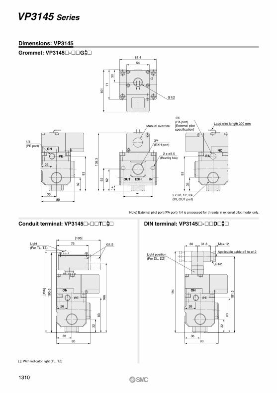
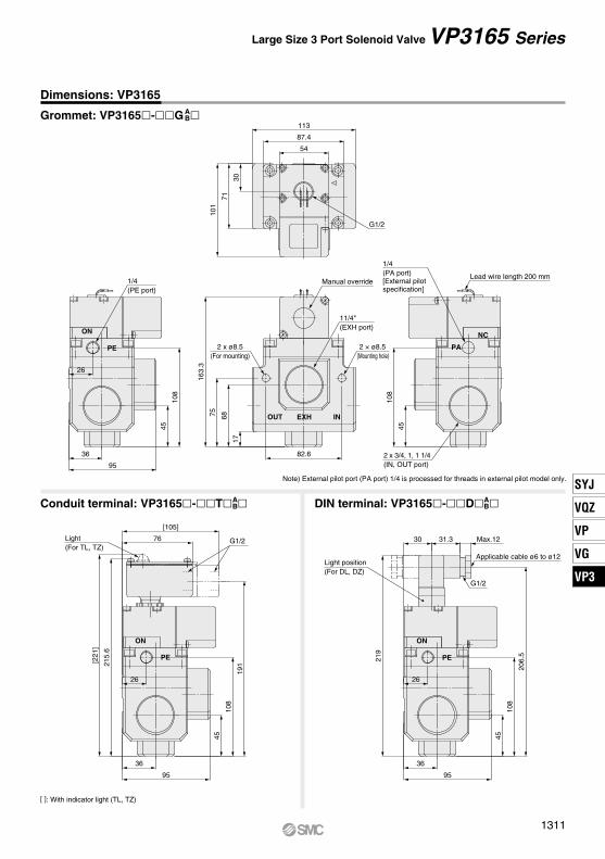
[ ]: With indicator light (TL, TZ)
Note) External pilot port (PA port) 1/4 is processed for threads in external pilot model only.
Dimensions: VP3145
Grommet: VP3145-G AB
Conduit terminal: VP3145-T AB DIN terminal: VP3145-D A
B
VP3145 Series
181.
5
Max.12
194
30 31.3
26
83
32
80
36
26
26
[196
]
190.
6
[105]
76
166
83
32
80
36
8383
32
138.
3
32
71
55 52
14
80
36
101
71
30
87.4
54
NONO
NC
NOLight(For TL, TZ)
Light position(For DL, DZ)
G1/2
Applicable cable ø6 to ø12
PE
G1/2
PE
G1/2
1/4(PA port)[External pilotspecification]
2 x ø8.5(Mounting hole)
2 x 3/8, 1/2, 3/4(IN, OUT port)
3/4(EXH port)
Manual override
1/4(PE port)
INEXHOUT
PAPE
Lead wire length 200 mm
1310
[ ]: With indicator light (TL, TZ)
Note) External pilot port (PA port) 1/4 is processed for threads in external pilot model only.
Dimensions: VP3165
Grommet: VP3165-G AB
Conduit terminal: VP3165-T AB DIN terminal: VP3165-D A
B
Large Size 3 Port Solenoid Valve VP3165 Series
30
206.
5
219
Max.1231.3
26
36
108
45
95
26
26
163.
3
101
71
30
[105]
76
[221
]
215.
6
191
36
108
45
95
36
108
45
108
45
113
87.4
54
68
82.6
75
17
95
NO
NC
NO
NO
Light position(For DL, DZ)
G1/2
Applicable cable ø6 to ø12
PE
11/4"(EXH port)
2 × ø8.5(Mounting hole)
G1/2
1/4(PA port)[External pilotspecification]
Lead wire length 200 mmManual override
G1/2
PE
1/4(PE port)
2 x ø8.5(For mounting)
2 x 3/4, 1, 1 1/4(IN, OUT port)
PA
OUT INEXH
PE
Light (For TL, TZ)
1311
SYJ
VQZ
VP
VG
VP3VP3
[ ]: With indicator light (TL, TZ)
Note) External pilot port (PA port) 1/4 is processed for threads in external pilot model only.
Dimensions: VP3185
Grommet: VP3185-G AB
Conduit terminal: VP3185-T AB DIN terminal: VP3185-D A
B
VP3185 Series
3131
31
185.
3
106
81
35
140
87.4
54
[243
]
237.
6
213
[110]
81 35
239
228.
5
130
52
105
41
Max.1231.3
130
52
105
41
130
52
105
41
130
14
52
95
80
118
NC
NO
NO NO
Light position(For DL, DZ)
2(EXH port)
2 x ø13(Mounting hole)
2 × 1 1/4, 1 1/2, 2(IN, OUT port)
G1/2
1/4(PA port)[External pilotspecification]
Lead wire length 200 mmManual override
G1/2
Applicable cable ø6 to ø12
G1/2
PEPE
PA
INEXHOUT
PE
Light(For TL, TZ)
1/4(PE port)
1312
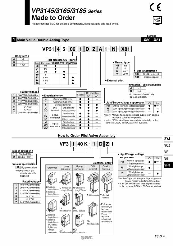
How to Order Pilot Valve Assembly
VP3145/3165/3185 Series
Made to OrderPlease contact SMC for detailed dimensions, specifications and lead times.
Symbol
-X80, -X81Main Value Double Acting Type1
1 D Z
1 D Z
A N065 14VP31
Grommet (300 mm)Grommet (600 mm)
Conduit terminalDIN
terminal
L plugconnector
M plugconnector
GHTD
DOL
LNLOM
MNMO
With connectorWithout connector
With lead wireWithout lead wireWithout connector
With lead wireWithout lead wireWithout connector
Electrical entry
X81
Port size (IN, OUT port)Symbol VP3145 VP3165 VP3185Port size
03040610121420
40VF3
DC
AC——
——————
U, Z spec.
—
AC Note 1)
—
DC
—
1K
468
1/21
1 1/2 3/81/23/41
1 1/41 1/2
2
Body size
1234567
100 VAC (50/60 Hz)200 VAC (50/60 Hz)110 VAC (50/60 Hz)220 VAC (50/60 Hz)
24 VDC12 VDC
240 VAC (50/60 Hz)
Rated voltage
1234567
100 VAC (50/60 Hz)200 VAC (50/60 Hz)110 VAC (50/60 Hz)220 VAC (50/60 Hz)
24 VDC12 VDC
240 VAC (50/60 Hz)
Rated voltage
X80X81
Double solenoidSingle solenoid
Type of actuation
12
Single (X81)Double (X80)
Type of actuation
K High pressure typePressure specification
Thread type
External pilot
NilFNT
RcG
NPTNPTF
AB
N.C.N.O.
Passage, Type of actuation
Light/Surge voltage suppressorNilUZ
Without light/surge voltage suppressorWith light/surge voltage suppressorWith light/surge voltage suppressor
Note 1) AC type has a surge voltage suppressor, since a rectifier is built into the product.
∗ In the DIN terminal type, since a light is installed in the connector, DOU and DOZ are not available.
Light/Surge voltagesuppressor
Nil
U
Z
Without light/surgevoltage suppressor
With light/surgevoltage suppressor
With light/surgevoltage suppressor
DC
—
AC
Note 1)
—
Note 1) AC type has a surge voltage suppressor, since a rectifier is built into the product.
∗ In the DIN terminal type, since a light is installed in the connector, DOU and DOZ are not available.
Electrical entry
GrommetConduitterminal
L plugconnector
M plugconnector
DINterminal
G: Lead wirelength 300 mm
H: Lead wirelength 600 mm
L: With lead wire(Length 300 mm)
LN:Without lead wire
LO:Without connector
M: With lead wire(Length 300 mm)
D: With connector T: Condaitterminal
DO:Without connector
MN:Without lead wire
MO:Without connector
∗E: Grommet terminal type has been discontinued. Please replace it with conduit terminal type.
Note) High pressure type should be selected for this product.
1
G: Lead wirelength 300 mm
H: Lead wirelength 600 mmDC without light/surge voltage suppressor
∗ In the case of -X80, onlyN.C. is available.
CE-compliant
1313
SYJ
VQZ
VP
VG
VP3VP3
A

PAPE
INEXHOUT
B A
(OUT)2
(OUT)2
(OUT)2
1(IN)
3(EXH)
X(PA)
1(IN)
3(EXH)
X(PA)
1(IN)
3(EXH)
X(PA)
N.C.
N.C. N.O.
Note 1) This solenoid valve requires lubrication. Use turbine oil Class 1 (ISO VG32).Note 2) Impact resistance: No malfunction occurred when it is tested with a drop tester in the axial
direction and at the right angles to the main valve and armature in both energized and de-energized states every once for each condition. (Values at the initial period)
Vibration resistance: No malfunction occurred in a one-sweep test between 45 and 1000 Hz. Test was performed at both energized and de-energized states in the axial direction and at the right angles to the main valve and armature. (Values at the initial period)
Valve configurationType of actuationFluidOperating pressure rangePilot pressureAmbient and fluid temperatureLubrication Note 1)
Mounting orientationImpact/Vibration resistance Note 2)
External pilot 3 port solenoid valveDouble solenoid (-X80), Single solenoid (-X81)
Air–101.2 kPa to 0.8 MPa
85 to 115% of main pressure, Min. 0.2 MPa0 to 50°C (No freezing)
Required (Equivalent to turbine oil Class 1 ISO VG32) Unrestricted150/50 m/s2
Specifications
Solenoid Specifications
Electrical entry
Coil rated voltage (V)
Allowable voltage fluctuation
AC (50/60 Hz)DC
Grommet, Conduit terminal, DIN terminalL plug connector, M plug connector
100, 200, 110, 220, 24024, 12
±10% of rated voltage
Piping and other usage are the same as standard products.
-X81
Symbol-X80
Power consumption (W)
∗ A rectifying circuit is used in the AC type.Note) At rated voltage
Apparent power (VA)
Note)
Note)
• In the case of B spec. of -X81 (N.O. spec.), VF3140K solenoid has to be positioned at left, when looking at the EXH port in the front face.
• In the case of -X80, VF3240K-1 (Pilot valve) will be mounted.
Caution
Dimensions
VP3145-DZA1-X81
VP3145/3165/3185 Series
DC
AC∗
Without indicator lightWith indicator light
1.55 (With indicator light: 1.65)DIN/Conduit terminal with indicator light: 1.7
1.51.55, DIN/Conduit terminal with indicator light: 1.75
204.
5
195.
5
93
42
36
Applicable cable O.D.ø4.5 to ø7
42
36
3/8, 1/2, 3/4(IN, OUT port)
1/4(External pilot port)
Max.10125.5
87.4
80 71
51
21.5
Pg9
71
10311
9
155
111.
5
6562
29
(40)
Manual override(Non-locking)
2 x 1/8(Pilot EXH port)
2 x ø8.5(For mounting)
3/4(EXH port)
22.6
(G
uide
)
1314B

PAPE
PAPE
INEXHOUT
B A
OUT INEXH
B A
• In the case of B spec. of -X81 (N.O. spec.), VF3140K solenoid has to be positioned at left, when looking at the EXH port in the front face.• In the case of -X80, VF3240K-1 (Pilot valve) will be mounted.
• In the case of B spec. of -X81 (N.O. spec.), VF3140K solenoid has to be positioned at left, when looking at the EXH port in the front face.• In the case of -X80, VF3240K-1 (Pilot valve) will be mounted.
Dimensions
VP3165-DZA1-X81
VP3185-DZA1-X81
Large Size 3 Port Solenoid Valve VP3145/3165/3185 Series
229.
5
220.
5
118
55
36
55
36
251.
5
242.
5
140
62
41
62
41
1/4(External pilot port)
3/4, 1, 1 1/4(IN, OUT port)
Applicable cable O.D.ø4.5 to ø7
Applicable cable O.D.ø4.5 to ø7
1/4(External pilot port)
1 1/4, 1 1/2, 2(IN, OUT port)
113
21.5
51
71
95
Pg9
82.6
12814
4
180
136.
5
8578
22.6
(Gui
de)
118
158.
5
105
90
15016
6
202
Pg9
87.4
140
151.8
105 81 76
56
26.5
22.6
(Gui
de)
138.3
87.4
(28)
29
(14)
29
Max.10
Manual override(Non-locking)
2 x ø13(For mounting)
2(EXH port)
2 x 1/8(Pilot EXH port)
1 1/4(EXH port)
2 x ø8.5(For mounting)
Manual override(Non-locking)
2 x 1/8(Pilot EXH port)
Max.10
1315
SYJ
VQZ
VP
VG
VP3VP3
A
“Items that are marked “With indicator light,” “With surge voltage suppressors,” and “With light/surge voltage suppressor” are all non-polar types.
Conduit terminal (T)Grommet (G) DIN terminal (D)
Light/Surge Voltage Suppressor
How to Use DIN Terminal
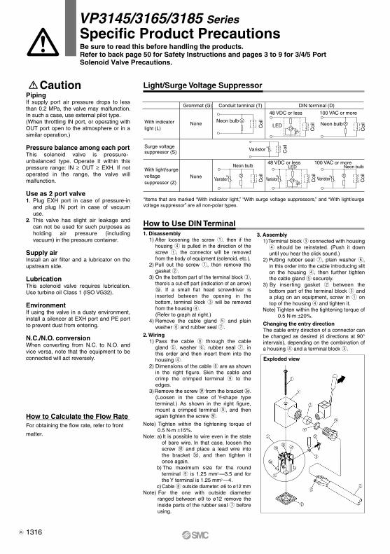
PipingIf supply port air pressure drops to less than 0.2 MPa, the valve may malfunction. In such a case, use external pilot type.(When throttling IN port, or operating with OUT port open to the atmosphere or in a similar operation.)
Pressure balance among each portThis solenoid valve is pressure-unbalanced type. Operate it within this pressure range: IN ≥ OUT ≥ EXH. If not operated in the range, the valve will malfunction.
Use as 2 port valve1. Plug EXH port in case of pressure-in
and plug IN port in case of vacuum use.
2. This valve has slight air leakage and can not be used for such purposes as holding air pressure (including vacuum) in the pressure container.
Supply airInstall an air filter and a lubricator on the upstream side.
LubricationThis solenoid valve requires lubrication. Use turbine oil Class 1 (ISO VG32).
EnvironmentIf using the valve in a dusty environment, install a silencer at EXH port and PE port to prevent dust from entering.
N.C./N.O. conversionWhen converting from N.C. to N.O. and vice versa, note that the equipment to be connected will act reversely.
None
NoneWith light/surgevoltagesuppressor (Z)
With indicatorlight (L)
Surge voltagesuppressor (S)
Coi
lC
oil
Coi
l
Coi
l
Coi
l
Coi
l
Coi
lNeon bulbNeon bulb
Neon bulb
100 VAC or more
48 VDC or less
Varistor
Varistor
100 VAC or moreNeon bulb
VaristorVaristor
48 VDC or less
LED
LED
How to Calculate the Flow RateFor obtaining the flow rate, refer to front
matter.
3. Assembly1) Terminal block e connected with housing
r should be reinstated. (Push it down until you hear the click sound.)
2) Putting rubber seal u, plain washer y, in this order into the cable introducing slit on the housing r, then further tighten the cable gland t securely.
3) By inserting gasket w between the bottom part of the terminal block e and a plug on an equipment, screw in q on top of the housing r and tighten it.
Note) Tighten within the tightening torque of 0.5 N·m ±20%.
Changing the entry directionThe cable entry direction of a connector can be changed as desired (4 directions at 90° intervals), depending on the combination of a housing r and a terminal block e.
1. Disassembly1) After loosening the screw q, then if the
housing r is pulled in the direction of the screw q, the connector will be removed from the body of equipment (solenoid, etc.).
2) Pull out the screw q, then remove the gasket w.
3) On the bottom part of the terminal block e, there’s a cut-off part (indication of an arrow) #a . If a small flat head screwdriver is inserted between the opening in the bottom, terminal block e will be removed from the housing r.(Refer to graph at right.)
4) Remove the cable gland t and plain washer y and rubber seal u.
2. Wiring1) Pass the cable i through the cable
gland t, washer y, rubber seal u, in this order and then insert them into the housing r.
2) Dimensions of the cable i are as shown in the right figure. Skin the cable and crimp the crimped terminal o to the edges.
3) Remove the screw #f from the bracket #e . (Loosen in the case of Y-shape type terminal.) As shown in the right figure, mount a crimped terminal o, and then again tighten the screw #f .
Note) Tighten within the tightening torque of 0.5 N·m ±15%.
Note: a) It is possible to wire even in the state of bare wire. In that case, loosen the screw #f and place a lead wire into the bracket #d , and then tighten it once again.
b) The maximum size for the round terminal o is 1.25 mm2 —3.5 and for the Y terminal is 1.25 mm2 —4.
c) Cable i outside diameter: ø6 to ø12 mmNote) For the one with outside diameter
ranged between ø9 to ø12 remove the inside parts of the rubber seal u before using.
Caution
VP3145/3165/3185 SeriesSpecific Product PrecautionsBe sure to read this before handling the products.Refer to back page 50 for Safety Instructions and pages 3 to 9 for 3/4/5 PortSolenoid Valve Precautions.
Exploded view
1316A