
Large-Eddy Simulations of a Dual-Mode Scramjet...
12
Large-Eddy Simulations of a Dual-Mode Scramjet Combustor: Operating Point “A” of University of Virginia’s Scramjet Experiments Wai Lee Chan * University of Michigan, Department of Aerospace Engineering, Ann Arbor, MI, 48109, U.S.A. Matthias Ihme † Stanford University, Department of Mechanical Engineering, Stanford, CA, 94305, U.S.A. Large-eddy simulations of the operating point “A” of the University of Virginia’s dual- mode scramjet experiments are performed with the objective to evaluate the applicability of the flamelet/progress variable combustion model to compressible reacting flow environ- ments. Results from this work will contribute to the ongoing efforts in advancing the incorporation of large-eddy simulation methodologies in the design of practical high-speed air-breathing propulsion systems. Reacting simulation results have shown qualitative agree- ments with previous numerical investigations and measurements for this operating point. Algorithmic development and modeling progress that enable the simulation of these flow- field environments are presented. Nomenclature t Time, s x Position, m ρ Density, kg/m 3 u Velocity, m/s ω Vorticity, 1/s Z Mixture-fraction C Progress variable ˙ ω C Source term for progress variable, kg/(m 3 · s) E Total energy, including chemical energy, J/kg h Sensible and chemical enthalpy, J/kg k Turbulent kinetic energy, J/kg p Pressure, Pa D Diffusion coefficient, m 2 /s μ Dynamic viscosity, Pa · s ν Kinematic viscosity, m 2 /s λ Thermal conductivity, W/(m · K) c p Specific heat capacity, J/(kg · K) τ ij Viscous stress tensor, N/m 2 Sc Schmidt number Pr Prandtl number φ General notation for conserved variables C φ Turbulent model coefficient for scalar φ Δ Local filter width * Graduate Student Research Assistant, Member AIAA. † Assistant Professor, Member AIAA. 1 of 12 American Institute of Aeronautics and Astronautics Downloaded by STANFORD UNIVERSITY on October 12, 2015 | http://arc.aiaa.org | DOI: 10.2514/6.2014-1161 52nd Aerospace Sciences Meeting 13-17 January 2014, National Harbor, Maryland AIAA 2014-1161 Copyright © 2014 by the American Institute of Aeronautics and Astronautics, Inc. All rights reserved. AIAA SciTech
Transcript of Large-Eddy Simulations of a Dual-Mode Scramjet...

Large-Eddy Simulations of a Dual-Mode Scramjet
Combustor: Operating Point “A” of University of
Virginia’s Scramjet Experiments
Wai Lee Chan∗
University of Michigan, Department of Aerospace Engineering, Ann Arbor, MI, 48109, U.S.A.
Matthias Ihme†
Stanford University, Department of Mechanical Engineering, Stanford, CA, 94305, U.S.A.
Large-eddy simulations of the operating point “A” of the University of Virginia’s dual-mode scramjet experiments are performed with the objective to evaluate the applicabilityof the flamelet/progress variable combustion model to compressible reacting flow environ-ments. Results from this work will contribute to the ongoing efforts in advancing theincorporation of large-eddy simulation methodologies in the design of practical high-speedair-breathing propulsion systems. Reacting simulation results have shown qualitative agree-ments with previous numerical investigations and measurements for this operating point.Algorithmic development and modeling progress that enable the simulation of these flow-field environments are presented.
Nomenclature
t Time, sx Position, mρ Density, kg/m3
u Velocity, m/sω Vorticity, 1/sZ Mixture-fractionC Progress variableωC Source term for progress variable, kg/(m3 · s)E Total energy, including chemical energy, J/kgh Sensible and chemical enthalpy, J/kgk Turbulent kinetic energy, J/kgp Pressure, PaD Diffusion coefficient, m2/sµ Dynamic viscosity, Pa · sν Kinematic viscosity, m2/sλ Thermal conductivity, W/(m ·K)cp Specific heat capacity, J/(kg ·K)τij Viscous stress tensor, N/m2
Sc Schmidt numberPr Prandtl numberφ General notation for conserved variablesCφ Turbulent model coefficient for scalar φ∆ Local filter width
∗Graduate Student Research Assistant, Member AIAA.†Assistant Professor, Member AIAA.
1 of 12
American Institute of Aeronautics and Astronautics
Dow
nloa
ded
by S
TA
NFO
RD
UN
IVE
RSI
TY
on
Oct
ober
12,
201
5 | h
ttp://
arc.
aiaa
.org
| D
OI:
10.
2514
/6.2
014-
1161
52nd Aerospace Sciences Meeting
13-17 January 2014, National Harbor, Maryland
AIAA 2014-1161
Copyright © 2014 by the American Institute of Aeronautics and Astronautics, Inc. All rights reserved.
AIAA SciTech

αN Nth criterion of shock-capturing schemeδij Kronecker deltaSubscripti, j, k, m Index notationres Resolved-scalet Subgrid-scale0 Stationary (total) conditionst Stoichiometric conditionrep Representative valueSuperscript′ Root-mean-square (fluctuations)′′ Residual
I. Introduction
High-speed propulsion systems, such as (sc)ramjet, have been considered for their relevance to long-rangestrike and access to orbit. The key advantage of these air-breathing propulsion systems, as compared toconventional rocket engines, is their reduced payload-cost and higher specific impulse. However, the downsideof these systems is the stringent requirement to operate over a wide range of operating conditions, in order tofacilitate the transition from a low Mach number takeoff to a high-speed supersonic cruise. For this reason,flight-testings of supersonic air-breathing vehicles are accompanied with prohibitive costs. Consequently,most experimental databases for these propulsion systems have been obtained in ground-test facilities, posingan intricate problem to the accurate representation of high-enthalpy flows in actual supersonic flights. Analternative to this issue is to make use of simulation techniques as a predictive tool for the design of thesehigh-speed air-breathing propulsion systems. While conventional Reynolds-Averaged Navier-Stokes (RANS)models have apparent disadvantages that will limit their applications to mere guidelines for the designof such complex configurations, the large-eddy simulation (LES) methods have promising capabilities toaccurately describe key features in the engine. In fact, as elaborated in a thorough review by Fureby,1 theLES methodology has been successful in simulating many supersonic configurations, including dual-modecombustors2 and scramjet facilities.3
However, as with all other novel technologies, the incorporation of numerical simulations in design pro-cedures for air-breathing propulsion systems first requires comprehensive validation of their accuracies; theUniversity of Virginia’s dual-mode scramjet experiments are designed exactly to accomplish this require-ment. Propagated by the National Center for Hypersonic Combined-Cycle Propulsion (NCHCCP) program,4
these scramjet experiments performed at the University of Virginia’s Supersonic Combustion Facility havecontributed to a unique and extensive set of benchmark data that will greatly benefit numerical model vali-dations. To date, non-intrusive diagnostic techniques that have been implemented include focused Schlierenand stereoscopic particle image velocimetry (SPIV),5 coherent anti-Stokes Raman spectroscopy (CARS),6
and planar laser induced fluorescence (PLIF),7 providing measurements of density gradient, velocity fields,hydroxyl radical concentration, temperature, and species mole-fractions. In addition, a numerical study thatutilized a hybrid LES/RANS method has also been conducted by Fulton et al.,8 presenting a preliminaryexamination of the predictive capabilities of CFD techniques.
The objective of the current study is to evaluate the performance of the steady flamelet/progress variable(F/PV) combustion model9,10 in the context of the operating point “A” of the University of Virginia’s (UV“A”) dual-mode scramjet experiments. Similar to other flamelet-based models, the fundamental concept ofthe F/PV approach is a mapping between all detailed thermochemical quanities and a lower-dimensionalmanifold, parameterized by two scalars, namely the the mixture-fraction, Z, and the reaction progressvariable, C. The advantages of the F/PV model include the precomputation and pretabulation of thethermochemical state-space prior to the simulation, the consideration of turbulence/chemistry interactionusing a presumed probability-density function approach, and the consideration of detailed reaction chemistryof arbitrary complexity. However, before we can fully utilize these advantages, it is crucial to first assessthe applicability of the F/PV model in high-speed combustion regimes, which are affected by complexaerothermodynamic phenomena. For example, non-linear interactions between turbulence and combustion,unsteady shock waves, scale-separation due to mixed regions of subsonic and supersonic flows, laminar-
2 of 12
American Institute of Aeronautics and Astronautics
Dow
nloa
ded
by S
TA
NFO
RD
UN
IVE
RSI
TY
on
Oct
ober
12,
201
5 | h
ttp://
arc.
aiaa
.org
| D
OI:
10.
2514
/6.2
014-
1161
turbulent transition, and real gas effects are some challenging yet common features that prevail in theUV “A” scramjet configuration. With the results of this work, we can confidently judge if the benefitsof the F/PV formulation will come at the expense of accuracy in representing high-speed reacting flows.Furthermore, this case will serve as the compressible supplement to previous work11 that analyzes theflamelet-formulation in a low Mach number jet in crossflow configuration. The UV “A”-configuration, thecomputational setups, such as boundary conditions and model closures, and the shock-detecting scheme thatwere considered in the present investigation are summarized in the next section. Instantaneous results thatcompare the performance of different shock-detecting scheme are presented in Sec. III, and the paper finisheswith conclusions and plans for future works.
II. Computational Setup
In the following, the setups that constitute the LES computations of the UV “A” scramjet configurationare presented. This discussion begins by presenting the LES-relevant Favre-filtered governing equations;model closures that have been applied to the unclosed terms in these filtered equations are also explained.In Sec. II.B, the geometry and operating conditions of the scramjet configuration and their correspondingnumerical treatments are described. A detail discussion of the shock-capturing method and the choice ofscalar transport equations is provided in Sec. II.C.
II.A. Governing Equations and Numerical Models
The UV “A” scramjet configuration operates in the supersonic scram-mode. As a result, the flow throughoutthe combustor-extender section will be predominantly supersonic. Therefore, the appropriate set of governingequations for this analysis corresponds to the compressible Navier-Stokes formulation, which will be filteredfor implementations in LES. Noting the convention that Reynolds-filtered and Favre-filtered variables are
denoted by (·) and (·), respectively, the relevant transport equations, in conservative form, are:
∂ρ
∂t+∂ρuj∂xj
= 0 , (1a)
∂ρui∂t
+∂ρuiuj∂xj
+∂p
∂xi=
∂
∂xj
[(µ+ µt)
(∂ui∂xj
+∂uj∂xi− 2
3δij∂uk∂xk
)− 2
3ρktδij
], (1b)
∂ρZ
∂t+∂ρujZ
∂xj=
∂
∂xj
[(ρD +
µtSct
)∂Z
∂xj
], (1c)
∂ρZ ′′2
∂t+∂ρujZ ′′2
∂xj=
∂
∂xj
[(ρD +
µtSct
)∂Z ′′2
∂xj
]−
2ρµtSct
(∂Z
∂xj
)2
− 2ρD˜(∂Z ′
∂xj
)2 , (1d)
∂ρC
∂t+∂ρujC
∂xj=
∂
∂xj
[(ρD +
µtSct
)∂C
∂xj
]+ ˜ωC , (1e)
∂ρE
∂t+∂ρujE
∂xj=
∂
∂xj
[(λ
cp+
µtPrt
)∂h
∂xj
]+
∂
∂xj[−ujp+ uiτij ] , (1f)
where Z ′′2 = Z2 − Z2 is the mixture-fraction variance. The terms kt = 0.5(u2i − ui
2)
and 2ρD ˜(∇Z ′)2 are
unclosed, and are modeled using the Vreman eddy-viscosity subgrid-scale model12 and spectral argument,13
respectively. These models are mathematically expressed as:
kt = νt |(aij + aji)| , (2a)
with νt = Cν
√Bβα2ij
, αij =∂uj∂xi
, βij = ∆2mαmiαmj , Bβ =
1
2
3∑j=1
3∑i=1
(βiiβjj − β2
ij
),
2ρD˜(∂Z ′
∂xj
)2
= ρCQZ ′′2(
µtSct∆2
), (2b)
3 of 12
American Institute of Aeronautics and Astronautics
Dow
nloa
ded
by S
TA
NFO
RD
UN
IVE
RSI
TY
on
Oct
ober
12,
201
5 | h
ttp://
arc.
aiaa
.org
| D
OI:
10.
2514
/6.2
014-
1161

where Cν and CQ are model constants set to 0.07 and 40, respectively. The value of the initial chosen modelconstant corresponds to the maximum theoretical magnitude of eddy viscosity in homogeneous isotropicturbulence, while that of the latter assumes a sufficiently high Reynolds number.
In the present work, the combustion phenomena is modeled by the steady flamelet/progress variable(F/PV) approach,9,10 with the reaction chemistry represented by a detailed hydrogen-air mechanism con-sisting of nine species and 19 elementary reactions.14
II.B. Geometry, Computational Domain, and Operating Conditions
The geometry and boundary-conditions of the computational domain are shown in Fig. 1. It should be noted,from Fig. 1(a), that this domain covers only part of the entire UV “A” scramjet configuration, namely theisolator, combustor, and extender sections, and excludes the upstream Mach 2 converging-diverging nozzle.Instead, as can be seen in Fig. 1(b), a uniform flow of air consisting of only streamwise velocity componentof 1035 m/s (corresponding to a Mach 2 flow based on the static thermodynamic state of p = 38 kPaand T = 667 K) is imposed at the inflow plane. The fuel-injection is described by a mean uniform flowof pure hydrogen with both streamwise and wall-normal velocity components of 1770 m/s and −220 m/s,respectively, corresponding to a Mach 1.7 condition based on static pressure and temperature of 94 kPaand 190 K, respectively. Artificially generated fluctuations are introduced to the mean fuel-flow to inducethe turbulent flow dynamics of the fuel-jet. The global equivalence-ratio that corresponds to these inflowconditions is 0.17, indicating a fuel-lean combustion regime. All walls that envelope the computationaldomain are prescribed with a no-slip condition and have constant wall-temperature of T = 600 K in thenon-reacting simulation. In the combusting case, the portion of the top wall and the ramp face, which arehighlighted in red in Fig. 1(a), have another isothermal condition of T = 1000 K. The marked walls andincreased wall-temperature are introduced to approximate the effect of the zirconia insulation applied atthese regions in the experiment. The outflow plane is assigned with characteristic boundary-conditions ofstationary thermodynamic states, p0 = 100 kPa and T0 = 1200 K.
0.64 cm
31.8 cm
2.54 cm
7.1° 2.9°
3.68 cm 6.67 cm
x z
x
y
4.76 cm
3.81 cm 1.27 cm
(a)
Air H2 (94 kPa, 190 K)
Outflow Isothermal Wall (600 K/1000 K)
Isothermal Wall (600 K)
(p0=100 kPa, T0=1200 K) (38 kPa, 667 K)
(b)
Figure 1. Schematic illustration of the (a) geometry and (b) boundary-conditions of the UV “A” scramjet configuration.As indicated by the various arrows, the general direction of the bulk flow is from left to right.
In addition to the boundary conditions for the hydrodynamic and thermodynamic variables, boundaryconditions for all transported scalars are also integral part of the simulation. In this regard, all transportedscalars enter the domain with a uniform profile of a certain prescribed value. Specifically, the values of
(Z, Z ′′2, C) are (0, 0, 0), (1, 0, 0), and (0, 0, 0) at the inflow plane, fuel-injection port, and outflow plane,
4 of 12
American Institute of Aeronautics and Astronautics
Dow
nloa
ded
by S
TA
NFO
RD
UN
IVE
RSI
TY
on
Oct
ober
12,
201
5 | h
ttp://
arc.
aiaa
.org
| D
OI:
10.
2514
/6.2
014-
1161

respectively.Based on the given operating conditions, a chemistry library was pretabulated using the FlameMaster-
code,15 assuming unity Lewis number for all species. This assumption is reasonable because the transportof species is expected to be dominated by the strong turbulence present in the flow. The current chemistrylibrary is represented by the “S”-shaped curve shown in Fig. 2, which depicts the state space projection ofunconvolved temperature and scalar dissipation rate conditioned on stoichiometric mixture-fraction, Zst =0.0285.
χst [1/s]
Tst [
K]
103
102
101
100
101
102
103500
1200
1900
2600
Tcrossover
= 912 K
χquench
= 252 1/s
Tquench
= 1217 K
Upper Branch
Middle Branch
Lower Branch
Figure 2. “S”-shaped curve corresponding to the UV “A” scramjet configuration and hydrogen-air mechanism due toBurke et al.;14 stoichiometric mixture-fraction is Zst = 0.0285.
From the “S”-shaped curve, we can see that the unstable middle branch is almost horizontal and levels atapproximately T = 912 K, which is the crossover temperature as pointed out by Hewson & Kerstein.16 Theflatness of the middle branch rules out classical flamelet ignition theory, which requires that the local scalardissipation rate be lower than a certain critical ignition value in order for self-ignition to occur. Therefore,reactions in our simulation were triggered by artificially rising the progress variable C to its maximum value.In order to aid in the development of the flame, the early reacting computations are also performed with onlythe stable upper branch of the “S”-shaped curve, thereby limiting the access of the chemistry library to justthe unquenched flame solutions. The eventual transition to the full chemistry library was implemented oncethe flame stabilized. It is noted that such procedure, while unphysical, is a common strategy in flamelet-basedsolvers to initiate a flame when auto-ignition is not a dominant flame ignition mechanism.
Currently, the computational domain is discretized by a mixed hexagonal-prism mesh, which consistsof approximately 10M control-volumes. The ratio of the unstructured elements (prism) relative to thestructured components (hexagonal) is 1.2%, indicating that the computational domain is still largely regular.In order to account for the high shear regions due to mixing of the fuel and the inflow air, the mesh hasbeen statically adapted to have a higher grid density within the volume between the fuel-injection face onthe ramp and its projection onto the outflow plane.
Computations of the non-reacting case have been performed on 960 cores of the IBM iDataPlex systemHaise at the Navy DoD Supercomputing Resource Center (DSRC), while that of the reacting case are doneusing 640 cores of the Cray XE6 system Garnet at the U.S. Army Engineer Research and DevelopmentCenter (ERDC). The computational cost is approximately 13,000 and 10,000 CPU-hours for one character-istic flow-through time of the non-reacting and reacting simulations, respectively. The flow-through timeis defined by the domain length from the fuel-injection port to the outflow plane (≈ 36.6 cm) and thefuel-injection speed (≈ 1780 m/s) and is equal to approximately 0.21 ms in physical units.
5 of 12
American Institute of Aeronautics and Astronautics
Dow
nloa
ded
by S
TA
NFO
RD
UN
IVE
RSI
TY
on
Oct
ober
12,
201
5 | h
ttp://
arc.
aiaa
.org
| D
OI:
10.
2514
/6.2
014-
1161
II.C. Modifications to the Flow Solver
In this study, all simulations are computed using Chris, a massively-parallel compressible reacting compu-tational fluid dynamics (CFD) solver developed by Cascade Technologies. However, due to the complexitiesof the UV “A” scramjet configuration, some critical modifications were required and are addressed in thefollowing.
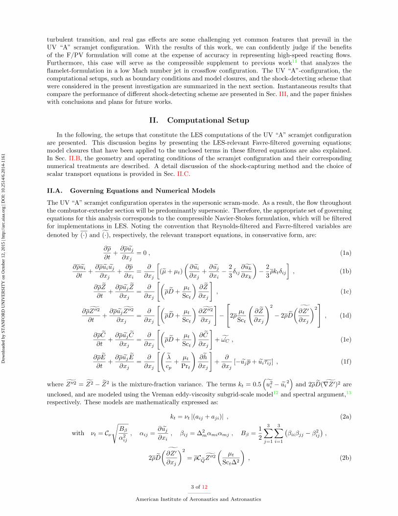
First, changes were made to the shock-detecting scheme, which will identify and apply the dissipativeessentially non-oscillatory (ENO) method to regions with shocks; the rest of the domain is computed usinga non-dissipative central differencing scheme. Initially, the shock-detection was based on two general condi-
tions: (i) overshooting in transported scalars (i.e. Z, Z ′′2 and/or C); and (ii) magnitude of gradient of theconserved variables, as stated in Eqs. (1). These criteria can be written as:
|φ| > α1 , (3a)(∂φ
∂xj
)2
∆2 > α22 × φ2rep . (3b)
It was found, by trial-and-error, that setting both α1 and α2 to 0.1 seems to give optimal results in termsof shock-capturing. This can be seen in Fig. 3(a) where the ENO scheme is mostly limited to regions thatcontain shocks or are highly strained by mixing of the reactants (i.e. red regions).
(a)
(b)
Figure 3. Illustration of the hybrid shock-capturing formulation based on the (a) old and (b) new criteria. Redareas indicate regions where ENO reconstruction has been flagged for implementation. Both figures correspond to thereacting case.
However, as will be further discussed, the previous shock-sensing criteria appear to be too aggressive.Specifically, the localized implementation of the ENO scheme at the high shear region adjacent to the fuel-injection port was found to laminarize the jet stream, delaying the process of jet breakdown and transitionto turbulence. In order to circumvent this issue, it is pertinent for the shock-detecting scheme to differentiatebetween shocks and shear-layers. Our approach to do so is by introducing a new criterion that compares themagnitude of dilatation to that of enstrophy. As pointed out by Ducros et al.,17 dilatation will be negligiblerelative to enstrophy in most part of a weakly compressible turbulent flow, except in the close vicinities ofa shock where dilatation can exceed enstrophy by an order-of-magnitude. The mathematical expression forthe dilatation-enstrophy criterion is given by:
∂uk∂xk
≥ α3
√ωkωk , (4)
where α3 is set to 0.2, within its typical range of [0.1, 1]. For the sake of numerical stability, the two initialcriteria have to be retained but at a much reduced magnitude, with α1 and α2 of 0.05 and 0.5, respec-tively. The superior performance of the modified shock-detecting scheme over its predecessor is illustratedin Fig. 3(b), where the implementation of the ENO scheme in the high shear region is vastly suppressed,delineating mostly just the shock fronts.
6 of 12
American Institute of Aeronautics and Astronautics
Dow
nloa
ded
by S
TA
NFO
RD
UN
IVE
RSI
TY
on
Oct
ober
12,
201
5 | h
ttp://
arc.
aiaa
.org
| D
OI:
10.
2514
/6.2
014-
1161

Another modification to Chris is the replacement of its default transport equation for Z2 by that for
Z ′′2, as shown in Eq. (1d). In contrast to Eq. (1d), previous experience showed that a transport equation
for Z2 is not realizable, allowing for the possibility of physically unrealistic Z ′′2 in the solutions.18 The
Eq. (1d), on the other hand, demonstrated that Z ′′2 will always be bounded within acceptable deviationsfrom its physical limits.
III. Results
In this section, we will evaluate the differences between the LES results before and after implementingthe modifications to Chris. The discussion of the reacting solutions will focus on three different planes,namely z = 0, x = 7.493 cm, and x = 11.303 cm. The latter streamwise planes correspond to two of the fourplanes where experimental CARS measurements of temperature are taken. On the other hand, only resultsalong the mid-plane will be presented for the non-reacting case since it is just conducted to provide a morerealistic base flow for the reacting simulations. Figure 4 shows an overview of the evaluated locations alongwith the outer geometry of the UV “A” scramjet configuration. The planar contour depicts instantaneoustemperature profile with stoichiometric mixture-fraction isoline. For convention, we will refer to the leanmixture adjacent to the top wall as the leeward side of the jet, while that next to the inflow air as thewindward side of the jet.
Figure 4. Isometric perspective of the scramjet geometry and the evaluated planes, z = 0, x = 7.493 cm, and x = 11.303 cm.The contour corresponds to the instantaneous temperature distributions and the black lines are the stoichiometricmixture-fraction isolines.
III.A. Prior to Shock-Detecting Scheme Modification
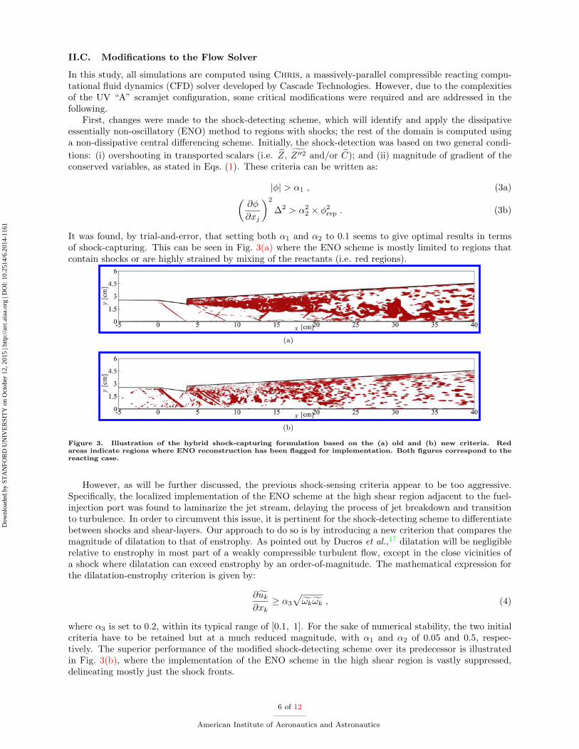
In Sec. II.C, we briefly mentioned that the previous shock-detecting scheme will erroneously laminarize thejet stream. Such artificial laminarization of the jet flow is undesirable because it will delay the jet’s laminar-turbulent transition, thereby directly affecting the mixing rate of the fuel and oxidizer streams. As a result,the flame stabilization point may be over-predicted and the entire combustion dynamics may be inaccurate.Even worse, since flameholding relies on a recirculation zone that is located in the leeward region close tothe fuel-injection port,8 this lag in the upstream reaction may lead to an eventual blowoff of the flame.
To demonstrate the unphysical laminarization of the jet, instantaneous temperature, pressure, andstreamwise velocity fields of the reacting case using the previous shock-detecting criteria with α1 = α2 = 0.1are shown in Fig. 5. The laminar-turbulent transition of the steady fuel jet is most obvious in the temperaturefield, where we can clearly observe: (i) a relatively homogeneous laminar region adjacent to the fuel-injectionpoint (3.7 < x < 5 cm); (ii) a shear-layer instability region (8 < x < 11 cm); (iii) an intermediate transitionregion (11 < x < 20 cm); and (iv) a dominantly turbulent region that lasts through the remaining part of thedomain (x > 20 cm). Comparing the transition region to that of the RANS/LES by Fulton et al.,8 however,it appears that the current simulation is too diffusive, exhibiting significantly less fine-scale structures thanthe reference case. This excessive diffusivity is exactly the consequence of the false laminarization of thejet induced by the shock-detecting scheme. Also, the notably higher temperature in the figure than that inFig. 4 is attributed to the utilization of just the upper stable branch of the “S”-shaped curve. The pressurecontour further illustrates that the shock sensor captures much area that does not contain any pressurejump, even though it does correctly identify discontinuities in the pressure field. The streamwise velocity
7 of 12
American Institute of Aeronautics and Astronautics
Dow
nloa
ded
by S
TA
NFO
RD
UN
IVE
RSI
TY
on
Oct
ober
12,
201
5 | h
ttp://
arc.
aiaa
.org
| D
OI:
10.
2514
/6.2
014-
1161
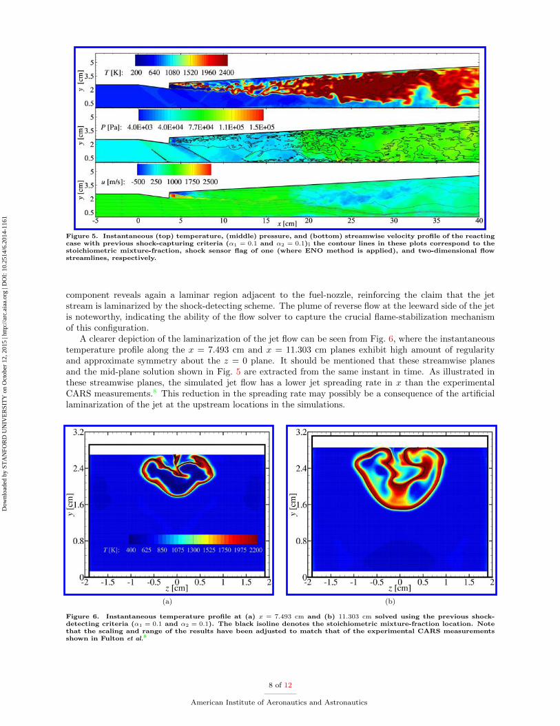
Figure 5. Instantaneous (top) temperature, (middle) pressure, and (bottom) streamwise velocity profile of the reactingcase with previous shock-capturing criteria (α1 = 0.1 and α2 = 0.1); the contour lines in these plots correspond to thestoichiometric mixture-fraction, shock sensor flag of one (where ENO method is applied), and two-dimensional flowstreamlines, respectively.
component reveals again a laminar region adjacent to the fuel-nozzle, reinforcing the claim that the jetstream is laminarized by the shock-detecting scheme. The plume of reverse flow at the leeward side of the jetis noteworthy, indicating the ability of the flow solver to capture the crucial flame-stabilization mechanismof this configuration.
A clearer depiction of the laminarization of the jet flow can be seen from Fig. 6, where the instantaneoustemperature profile along the x = 7.493 cm and x = 11.303 cm planes exhibit high amount of regularityand approximate symmetry about the z = 0 plane. It should be mentioned that these streamwise planesand the mid-plane solution shown in Fig. 5 are extracted from the same instant in time. As illustrated inthese streamwise planes, the simulated jet flow has a lower jet spreading rate in x than the experimentalCARS measurements.8 This reduction in the spreading rate may possibly be a consequence of the artificiallaminarization of the jet at the upstream locations in the simulations.
(a) (b)
Figure 6. Instantaneous temperature profile at (a) x = 7.493 cm and (b) 11.303 cm solved using the previous shock-detecting criteria (α1 = 0.1 and α2 = 0.1). The black isoline denotes the stoichiometric mixture-fraction location. Notethat the scaling and range of the results have been adjusted to match that of the experimental CARS measurementsshown in Fulton et al.8
8 of 12
American Institute of Aeronautics and Astronautics
Dow
nloa
ded
by S
TA
NFO
RD
UN
IVE
RSI
TY
on
Oct
ober
12,
201
5 | h
ttp://
arc.
aiaa
.org
| D
OI:
10.
2514
/6.2
014-
1161

Temperature, pressure, and u-velocity profiles of one snapshot of the non-reacting run are shown inFig. 7. Since a similar laminar jet flow can be discerned from this temperature contour, we can rule outthe possibility that the excessive chemical reaction in the aforementioned reacting case, due to utilizationof only the upper stable branch of the “S”-shaped curve, is not the cause of the jet laminarization. Fromthe pressure plot, one can see that the ENO method is applied to a significantly larger area, which does notnecessarily contain any shock or shear-layer, than that shown in Fig. 5. This discrepancy in the behaviorof the shock-detecting scheme is due to the choice of the shock-sensing parameters of the non-reacting case,α1 = 0.1 and α2 = 0.05, which differ from the observed optimal combination of 0.1 for both α1 and α2. Wenote that a recirculation zone, albeit weaker, is also present in the non-reacting case, demonstrating onceagain that Chris will correctly account for important flow features.
Figure 7. Instantaneous (top) temperature, (middle) pressure, and (bottom) streamwise velocity profile of the non-reacting case with previous shock-capturing criteria (α1 = 0.1 and α2 = 0.05). Plot conventions are the same as thatdefined by Fig. 5.
III.B. Post Shock-Detecting Scheme Modification
In the following, the results for the reacting run using the new shock-detecting criteria are evaluated. Thechosen combination for the shock-sensing parameters is, as described in Sec. II.C, α1 = 0.05, α2 = 0.5,and α3 = 0.2, which seems to be able to capture compressible phenomena effectively without jeopardizingthe stability of the numerics. Fig. 8 shows the temperature, pressure, and streamwise velocity profilesresulting from the modification of the shock-detecting scheme. Unlike the temperature plot in Fig. 5, thecurrent temperature contour clearly has more turbulent structures. Sign of a fully-developed turbulent flameoccurs as early as x ≈ 13 cm, and the streamwise penetration of the stoichiometric mixture-fraction isreduced by as much as 50%, indicating a higher mixing rate. The contributing factor that alleviated thejet laminarization issue is the reduction of the influence of the ENO method at the shear-layer vicinities,particularly at the leeward side of the jet, as seen in the pressure plot. This improvement in the predictionof the breakdown of the jet indicates that the new shock-detecting scheme is indeed effective. Similar tothe earlier streamwise velocity distributions, the u-profile in Fig. 8 still displays a noticeable flameholdingrecirculation zone, although the jet stream now exhibits a pulsating-like profile that is unseen previously.Referring to the corresponding streamwise planes x = 7.493 cm and x = 11.303 cm, as shown in Fig. 9,the temperature profile is obviously more chaotic and no longer preserves a symmetry about the mid-plane.The jet also appears to be more widespread than before, suggesting again that turbulence increases the jetspreading rate in x. It should be mentioned that the results in Fig. 8 are computed using the full chemistrylibrary, in contrast to that shown in Figs. 5 and 6.
9 of 12
American Institute of Aeronautics and Astronautics
Dow
nloa
ded
by S
TA
NFO
RD
UN
IVE
RSI
TY
on
Oct
ober
12,
201
5 | h
ttp://
arc.
aiaa
.org
| D
OI:
10.
2514
/6.2
014-
1161

Figure 8. Instantaneous (top) temperature, (middle) pressure, and (bottom) streamwise velocity profile of the reactingcase with new shock-capturing criteria (α1 = 0.05, α2 = 0.5, and α3 = 0.2). Plot conventions are the same as that definedby Fig. 5.
(a) (b)
Figure 9. Instantaneous temperature profile at (a) x = 7.493 cm and (b) 11.303 cm solved using the new shock-capturingcriteria (α1 = 0.05, α2 = 0.5, and α3 = 0.2). Plot conventions are the same as that defined by Fig. 6.
IV. Conclusions
A study that involves the large-eddy simulations of a reacting scramjet is currently being conducted. Thegeometry of the scramjet of interest corresponds to the “A”-configuration of the University of Virginia’s dual-mode scramjet experiments, which is designed to emulate flight conditions at Mach 5 enthalpy. Computationshave been performed for both the non-reacting and reacting cases using a massively-parallel compressiblereacting solver Chris, which is developed by Cascade Technologies. The current hybrid mesh consists ofapproximately 10M control-volumes at a ratio of 1.2% between the unstructured and structured elements.Evaluations have shown that: (i) The shock-detecting scheme has significant influence on the development ofturbulent structures in the flame, especially in the upstream close-nozzle region. In this regard, the dilatation-enstrophy criterion developed by Ducros et al.17 appears to be an effective and necessary complement tothe default shock-capturing criteria in Chris. (ii) The recirculation zone at the leeward side of the jet ispresent regardless of the case, non-reacting or reacting, and laminarity of the jet stream, suggesting thatthis region is an inherent feature of the scramjet design. This feature is desirable because the recirculation
10 of 12
American Institute of Aeronautics and Astronautics
Dow
nloa
ded
by S
TA
NFO
RD
UN
IVE
RSI
TY
on
Oct
ober
12,
201
5 | h
ttp://
arc.
aiaa
.org
| D
OI:
10.
2514
/6.2
014-
1161
zone can provide a flame-anchoring mechanism that sustains combustion in the system.8 (iii) Transportedquantities are in qualitative agreement with a previous numerical study conducted by Fulton et al.,8 whichhas demonstrated reasonable agreements with its experimental counterpart. (iv) Consistent with Kemenov
et al.,18 the transport equation of Z ′′2 is found to be much better behaving than that of Z2.An outline of the planned work is as follows:
• Converged solutions of the reacting case will be qualitatively and quantitatively compared with theextensive experimental database, which consist of dual-pump coherent anti-Stokes Raman spectroscopy,particle imaging velocimetry, and planar laser-induced fluorescence diagnostics for temperature andspecies mole-fraction, velocity, and hydroxyl radical concentration.
• Parametric studies on the boundary-conditions will be performed to assess the effects of includ-ing/excluding some geometrical features of the scramjet configuration, such as the converging-divergingMach 2 and conical fuel-injection nozzles, the importance of turbulent fluctuations in the fuel-injectionprofile, and the appropriateness of the characteristic total outflow boundary-condition.
• Sensitivities of the results to various model closures (e.g. preferential-diffusion phenomenon, andflamelet presumed probability-density-function assumption) will be investigated to identify the poten-tial cause of errors and limitations in the simulations.
Acknowledgments
Financial support through the Air Force Office of Scientific Research under Award No. FA9550-11-1-0031is gratefully acknowledged.
References
1Fureby, C., “LES for supersonic combustion,” 18th AIAA/3AF International Space Planes and Hypersonic Systems andTechnologies Conference, AIAA 2012-5979, Tours, France, 2012.
2Micka, D. J. and Driscoll, J. F., “Combustion characteristics of a dual-mode scramjet combustor with cavity flameholder,”Proc. Combust. Inst., 32, 2009, pp. 2397–2404.
3Paull, A., Alesi, H., and Anderson, S., “The HyShot Flight Program and how it was Developed,” AIAA-AAAF 11th Int.Space Planes and Hypersonic Systems and Technologies Conference, Orleans, France, 2002.
4McDaniel, J. C., Chelliah, H., Goyne, C. P., Edwards, J. R., Givi, P., and Cutler, A. D., “US National Center forHypesonic Combined Cycle Propulsion: An overview,” 16th AIAA/DLR/DGLR International Space Planes and HypersonicSystems and Technologies Conference, AIAA 2009-7280, Bremen, Germany, 2009.
5Rockwell, R. D., J., Goyne, C. P., Rice, B. E., Tatman, B. J., Smith, C., Kouchi, T., McDaniel, J. C., Fulton, J. A., andEdwards, J. R., “Close-collaborative experimental and computational study of a dual-mode scramjet combustor,” 50th AIAAAerospace Sciences Meeting including the New Horizons Forum and Aerospace Exposition, AIAA 2012-0113, Nashville, TN,2012.
6Cutler, A. D., Magnotti, G., Cantu, L., Gallo, E., Danehy, P. M., Rockwell, R., Goyne, C., and McDaniel, J., “Dual-pumpCARS measurements in the Univesity of Virginia’s dual-mode scramjet: Configuration “A”,” 50th AIAA Aerospace SciencesMeeting including the New Horizons Forum and Aerospace Exposition, AIAA 2012-0114, Nashville, TN, 2012.
7Johansen, C. T., McRae, C. D., Danehy, P. M., Gallo, E., Cantu, L., Magnotti, G., Cutler, A., Rockwell, R. D., Goyne,C. P., and McDaniel, J. C., “OH PLIF Visualization of the UVa Supersonic Combustion Experiment: Configuraton A,” 50thAIAA Aerospace Sciences Meeting including the New Horizons Forum and Aerospace Exposition, AIAA 2012-2887, Nashville,TN, 2012.
8Fulton, J. A., Edwards, J. R., Hassan, H. A., Rockwell, R., Goyne, C., McDaniel, J., Smith, C., Cutler, A., Johansen, C.,Danehy, P. M., and Kouchi, T., “Large-Eddy/Reynolds-Averaged Navier-Stokes simulations of a dual-mode scramjet combus-tor,” 50th AIAA Aerospace Sciences Meeting including the New Horizons Forum and Aerospace Exposition, AIAA 2012-0115,Nashville, TN, 2012.
9Pierce, C. D. and Moin, P., “Progress-variable approach for large-eddy simulation of non-premixed turbulent combustion,”J. Fluid Mech., Vol. 504, 2004, pp. 73–97.
10Ihme, M., Cha, C. M., and Pitsch, H., “Prediction of local extinction and re-ignition effects in non-premixed turbulentcombustion using a flamelet/progress variable approach,” Proc. Combust. Inst., Vol. 30, 2005, pp. 793–800.
11Chan, W. L., See, Y. C., Ihme, M., Kolla, H., and Chen, J. H., “Budget analysis and model-assessment of the flamelet-formulation: Application to a reacting jet-in-cross-flow,” Proceedings of the Summer Program, Center for Turbulence Research,2012, pp. 397–407.
12Vreman, A. W., “An eddy-viscosity subgrid-scale model for turbulent shear flow: Algebraic theory and applications,”Phys. Fluids, Vol. 16, No. 10, 2004, pp. 3670–3681.
13Ihme, M., Pollutant formation and noise emission in turbulent non-premixed flames, Ph.D. thesis, Stanford University,2007.
11 of 12
American Institute of Aeronautics and Astronautics
Dow
nloa
ded
by S
TA
NFO
RD
UN
IVE
RSI
TY
on
Oct
ober
12,
201
5 | h
ttp://
arc.
aiaa
.org
| D
OI:
10.
2514
/6.2
014-
1161
14Burke, M. P., Chaos, M., Ju, Y., Dryer, F. L., and Klippenstein, S. J., “Comprehensive H2/O2 Kinetic Model forHigh-Pressure Combustion,” Int. J. Chem. Kinet., Vol. 44, No. 7, 2011, pp. 444–464.
15Pitsch, H., “FlameMaster v3.1: A C++ computer program for 0D combustion and 1D laminar flame calculations,”1998.
16Hewson, J. C. and Kerstein, A. R., “Local extinction and reignition in nonpremixed turbulent CO/H2/N2 jet flames,”Comb. Theory Modelling, Vol. 174, 2002, pp. 35–66.
17Ducros, F., Ferrand, V., Nicoud, F., Weber, C., Darracq, D., Gacherieu, C., and Poinsot, T., “Large-Eddy Simulation ofthe Shock/Turbulence Interaction,” J. Comp. Phys., Vol. 152, 1999, pp. 517–549.
18Kemenov, K. A., Wang, H., and Pope, S. B., “Modelling effects of subgrid-scale mixture fraction variance in LES of apiloted diffusion flame,” Comb. Theory Modelling, Vol. 16, 2012, pp. 611–638.
12 of 12
American Institute of Aeronautics and Astronautics
Dow
nloa
ded
by S
TA
NFO
RD
UN
IVE
RSI
TY
on
Oct
ober
12,
201
5 | h
ttp://
arc.
aiaa
.org
| D
OI:
10.
2514
/6.2
014-
1161


