LARGE DEFORMATION OF THIN PLATES UNDER LOCALISED IMPULSIVE LOADING...
20
Pergamon Int. d. Impact Engng Vol. 18, Nos 7-8, pp. 899 918, 1996 Copyright © 1996 ElsevierScienceLtd Printed in Great Britain. All rights reserved PII:SO734-743X(96)O0027-9 0734 743X/96 $15.00+0.00 LARGE DEFORMATION OF THIN PLATES UNDER LOCALISED IMPULSIVE LOADING T. WlERZBICKI* and G. N. NURICK * Department of Ocean Engineering, Massachusettes Institute of Technology, Cambridge, MA 02139, U.S.A. and Department of Mechanical Engineering, University of Cape Town, Rondebosch, 7700, South Africa (Received 10 May 1996; in revised form 7 June 1996) Summary--The response of thin clamped plates to a localised impulsive load imparted over a central circular region is investigated experimentally and theoretically to determine the location of tearing failure and the critical impulse to failure. Over 40 tests were performed with four different loading radii and increasing values of the applied impulse. Typical dish like deflection profiles were produced and measured. It was observed that smaller loading radii led to a more localised bulging near the plate centre. The resulting plate failure took the form of a disc. A more distributed load produced tearing failure at the clamped boundary. In the theoretical development, the plate was modelled as a rigid-plastic membrane. The resulting initial-boundary value problem for the wave equation in the polar co-ordinate system was solved by the eigenfunction expansion method up to the point of first unloading. An approximate closed-form solution was also obtained by combining the wave form solution for early motion with the mode solution for late motion. A good correlation was obtained between the predicted and measured normalised deflection profile. The analysis of the theoretical solution gave strong indication that the initial velocity profile must have a form of a continuous and smooth function near the edge of the burning zone. Precise determination of the deflected shape is a necessary step for strain calculations and the prediction of the onset of tensile necking and failure of plates. Copyright © 1996 Elsevier Science Ltd. Keywords: impulsive loading, plastic membranes, large deflections, failure. C Cb h m= p F t t'= tf U W W£ A. I Jo, J~ N, No N o = H R Rb V ~= ~r loading radius plastic transverse wave speed burn speed of explosive plate thickness ph--mass density per unit area transverse pressure radial coordinate r/R--dimensionless radial coordinate time tc/R--dimensionless time response time radial displacement transverse displacement w/R dimensionless displacement final deflection expansion coefficients total impulse Bassel functions radial membrane force circumferential membrane force a0h--fully plastic membrane force thickness of padding foam outer radius of the plate burn radius transverse velocity a/R dimensionless load radius Rb/R dimensionless burn radius Vo/c dimensionless velocity radial strain eigenvalues eigenfunctions NOTATION 899
-
Upload
hoangkhuong -
Category
Documents
-
view
215 -
download
1
Transcript of LARGE DEFORMATION OF THIN PLATES UNDER LOCALISED IMPULSIVE LOADING...

Pergamon Int. d. Impact Engng Vol. 18, Nos 7-8, pp. 899 918, 1996
Copyright © 1996 Elsevier Science Ltd Printed in Great Britain. All rights reserved
PII:SO734-743X(96)O0027-9 0734 743X/96 $15.00+0.00
LARGE DEFORMATION OF THIN PLATES UNDER LOCALISED IMPULSIVE LOADING
T. WlERZBICKI* and G. N. NURICK * Department of Ocean Engineering, Massachusettes Institute of Technology, Cambridge, MA 02139, U.S.A. and Department of Mechanical Engineering, University of Cape Town,
Rondebosch, 7700, South Africa
(Received 10 May 1996; in revised form 7 June 1996)
Summary--The response of thin clamped plates to a localised impulsive load imparted over a central circular region is investigated experimentally and theoretically to determine the location of tearing failure and the critical impulse to failure. Over 40 tests were performed with four different loading radii and increasing values of the applied impulse. Typical dish like deflection profiles were produced and measured. It was observed that smaller loading radii led to a more localised bulging near the plate centre. The resulting plate failure took the form of a disc. A more distributed load produced tearing failure at the clamped boundary.
In the theoretical development, the plate was modelled as a rigid-plastic membrane. The resulting initial-boundary value problem for the wave equation in the polar co-ordinate system was solved by the eigenfunction expansion method up to the point of first unloading. An approximate closed-form solution was also obtained by combining the wave form solution for early motion with the mode solution for late motion. A good correlation was obtained between the predicted and measured normalised deflection profile. The analysis of the theoretical solution gave strong indication that the initial velocity profile must have a form of a continuous and smooth function near the edge of the burning zone. Precise determination of the deflected shape is a necessary step for strain calculations and the prediction of the onset of tensile necking and failure of plates. Copyright © 1996 Elsevier Science Ltd.
Keywords: impulsive loading, plastic membranes, large deflections, failure.
C
Cb
h m =
p F
t
t'= tf U W
W£ A. I Jo, J~ N, No N o = H R Rb V
~=
~r
loading radius plastic transverse wave speed burn speed of explosive plate thickness ph--mass density per unit area transverse pressure radial coordinate r/R--dimensionless radial coordinate time tc/R--dimensionless time response time radial displacement transverse displacement w/R dimensionless displacement final deflection expansion coefficients total impulse Bassel functions radial membrane force circumferential membrane force a0h--fully plastic membrane force thickness of padding foam outer radius of the plate burn radius transverse velocity a/R dimensionless load radius Rb/R dimensionless burn radius Vo/c dimensionless velocity radial strain eigenvalues eigenfunctions
NOTATION
899

900 T. Wierzbicki and G. N. Nurick
A kinetic energy functional p mass density G O flow stress
1. INTRODUCTION
The present paper is concerned with an experimental and theoretical study of final deflection profiles of thin circular plates subjected to explosive loading imparted to the central portion of the plate. A precise determination of the deflection function is an important step in predicting an onset of tensile or shear failure of plates. Tests were run for several radii of the central loading area, with an increasing magnitude of the impulsive loading up to the point of fracture. It was found that the permanent shape of the plate depends on the loading radius and distribution of initial velocity. Local loading gives rise to deflection profiles with a distinct bulge near the centre while a more distributed load produced a smooth dishing of the plate.
The published work on this subject was restricted almost exclusively to impulsive and pulse loading which was uniformly distributed over the entire plate surface. For the review of the relevant literature the reader is referred to the article by Nurick and Martin [ 1 ]. For small magnitudes of the applied impulse the resulting deflections are small and the plate response is governed by bending and/or shear resistance. Response of plates subjected to high intensity impulsive loading and undergoing large deflections is dominated by a membrane stretching resistance. Such plates, or more precisely plastic membranes, are the subject of the present study. Tests on dynamically loaded circular membranes were carried out by Florence [2],Ghosh and Weber [3], Bodner and Symonds [4], Nurick and Martin [5], Teeling-Smith and Nurick[6].
In the theoretical formulation of large deflection problem of membranes there has been a general agreement among the researchers that internal energy dissipation occurs predomi- nantly through action of membrane forces on middle surface strains and flexural work could be neglected. Furthermore, only transverse deflections, w, were considered, while the effect of the in-plane displacement, u, was of second order. Several approximate techniques were proposed in the literature to solve the resulting initial-boundary value problem. Baker [7] and Duffey [81 among others, used an energy method for rigid-plastic material behaviour and equated the dissipated strain energy to the initial kinetic energy imparted to the circular membrane. Several deformed shape profiles were assumed, including sinusoidal and various polynomial forms to find the best fit of the experimental results. Further steps in developing approximate methods were taken by Jones I-9] and Symonds and Wierzbicki [10] who calculated rather than assumed the stationary mode shape by solving a linear eigenvalue problem. In the latter formulation the solution did satisfy the field equations and boundary conditions but not the initial condition. The initial conditions were satified "on average" through the minimisation of the "difference" kinetic energy. This approach known as a "mode approximation technique" proposed originally by Martin and Symonds [11"1 for small deflection problems was applied with great success in Refs 1-12] and [ 13.1 to moderately large deflection problems of plastic plates and membranes. The above mentioned approxi- mate method gives generally good predictions of the central deflection when strain hardening and strain sensitivity is taken into account [6, 10].
The objective of the present paper is to get a further insight into the response of circular membranes to explosive loading applied over a circular area of radius a. Over 40 tests were run with different magnitudes of total impulse and ratios a/R, where R is the plate radius. Measured in the experiments were the total impulse I and the final deformed profile of the membranes. In principle, the present experimental arrangement was similar to that used by Bodner and Symonds [4] who also performed explosive tests with three radii of the loaded area a/R = 1/3, 1/2, 1. However, except for one set of data, no measurements of the deflected shape of the plate were reported in this paper. In the follow-up publication, Symonds and Wierzbicki [10] presented an approximate solution of the problem and obtained a good correlation for the central deflection. No attempts were made to determine the shape of the deflected curve on purely theoretical grounds.

Large deformation of thin plates 901
The analysis of partially loaded membranes poses considerable difficulties in comparison to similar structures loaded by a uniformly distributed impulse over the entire surface of the membrane. First, there is a distinct transient phase of the response in which a plastic transverse wave propagates from the loading area outwards towards the support and inward towards the centre. Two new solution techniques based on momentum conservation and an eigenvalue expansion method were developed to treat this phase analytically. Secondly, the distribution of pressure amplitude and the resulting initial velocity can not be easily determined from the tests alone. In order to overcome the above difficulty several different trapesoidal distributions of initial velocity were considered to see which one gives the best correlation with the experimentally measured profile. A good qualitative agreement with the tests was obtained which opens a way for more precise strain calculations and predictions of the onset of tearing fracture.
2. EXPERIMENTAL PROCEDURE AND RESULTS
The experimental procedure used is similar to that used by Bodner and Symonds [4], and Teeling-Smith and Nurick [6]. The plates were centrally loaded using a plastic explosive (PE 4), with an approximate burn speed of Cb = 7500 m/s. This explosive was spread evenly onto a polystyrene foam pad over the load diameters a = 18.3 mm, 25 mm, 33 mm, 40 mm and 100 mm with a detonator in the centre. Differing thicknesses of explosive were used giving different impulses, resulting in deformations ranging from two to seven plate thicknesses. The foam pads had a diameter equal to the plate diameter of 100mm and an approximate thickness of H = 12 mm, and disintegrated on detonation (Fig. 1). The test plates were made from hot rolled mild steel and had an outer diameter of R = 100 mm and thickness of h = 1.6 mm (Fig. 2).
Experimental data included measurements of total impulse, mid-point deflection and plate profile. The plate profile for the plate radius greater than the loaded radius was observed to be similar to that of a uniformly loaded plate, with a nipple shaped profile at the central loaded area of the plate. The plate deformation increased with increased impulse, with significant thinning through the thickness of the plate at the outer radius of the nipple. The radius at which thinning took place was proportional to the load diameter. At high impulses, the central cap was blown from the plate. Tearing was also observed at the boundary for one experiment of the 40 mm load diameter. Investigation of the loaded side of the plate revealed a discolorisation which is interpreted as the burning due to the high temperature of the explosive. Both the burn radius, R b and the cap radius were proporti- onal to the load diameter. Photographs of deflected plates for two load diameters and increasing magnitudes of applied impulse are shown in Fig. 3. Normalised experimental deflection profiles for five values of load diameter are plotted in Fig. 4.
DETONATION AT THE CENTRE
~ ~ _ CLAMPING RIG Fig. 1. Experimental set-up.

902 T. Wierzbicki and G. N. Nurick
R ' a
I / I l L
t=O ; t
i
Fig. 2. Plate geometry and loading configuration.
Fig. 3. Plasticity deformed specimens for increasing load intensity.

Large deformation of thin plates 903
0 , 9 -
0.8-
"~ 0.7-
8 ,, 0 .6-
,~ 0,5-
- 0 .4-
o 0.3-
0.2-
0.1
0 0
. . . . . . . . . . . . . . . . . . . . . . . . . . . . . . . . . . . . . . . . . . . . . . . . . . . . . . . . . . . . . . . . . . . . . . . . . . . . . . . . . . . . . . . . . . t ' . , ~ . ~ . . . . . . . . . . . . . . . . . . . . . . . .
0.1 0.2 0.3 0.4 0.5 0.6 0.7 0.8 0.9 NorTnalised distance from plata centre
- - load radius = 0.183 . . . . . . . . . . . load radius = 0.25 - - ]oad radius = 0.33
............ load radius 0.40 ...... load radius 1.0
Fig. 4. Normalised experimental deflection profiles of plates showing the effect of the loading radius ~ = a/R.
3. D E V E L O P M E N T OF THE MATHEMATICAL M O D E L
Consider a plate (membrane) of thickness h firmly clamped at an outer radius r = R. A total impulse, I, is imparted to a central circular area with a radius r = a (Fig. 2). In order to simplyfy the problem, the following assumptions are made:
1. the load intensity is high enough to produce maximum permanent deflections larger than several multiples of the plate thickness;
2. elastic effects are disregarded; 3. plate material is assumed to be rigid-perfectly plastic with an elevated but constant
magnitude of flow stress t~ o. The flow stress can be suitably adjusted for strain hardening and strain sensitivity; and
4. the material particles follow straight trajectories, normal to the undeformed surface of the plate. Consequently, the in-plane component of the displacement vector vanishes, u = 0. The out-of-plane component is denoted by w(r).
Under the above assumptions the only non-vanishing component of the middle surface strain tensor is the radial component e,. In the moderately large deflection theory of plates radial strains and strain rates are
1 (0w']2; 0w0~ 0r 0r (1)
where a dot designates differentiation with respect to time. The corresponding equation of dynamic equilibrium takes the form
O f Ow \ -~r tr ~r N, ) = mr~ (2)
where m = hp is mass density per unit area and N, is the radial membrane force per unit length N, = ha,. Because of asumption 4, the circumferential membrane force N o is treated as a reaction. Further simplications are obtained by assuming the Tresca yield condition. The associated flow rule implies that the stress profile of a clamped plate must lie on the segment

904 T. Wierzbicki and G. N. Nurick
of the Tresca hexagon described by N, = N o. The equation of motion (2) is then reduced to a linear wave equation in the polar coordinate system
where
C 2 ~ r ~ r ~ r ) = r f v (3)
,4,
is the velocity of the transverse plastic wave. The intrinsic nonlinearity of plasticity enters the present problem through the unloading criterion. In the case of one-dimensional stress the flow rule takes the form
N r = Nosign ~,. (5)
Plastic flow takes place for positive (or negative) radial strain rates. Material elements become rigid whenever 4, = 0. Linear wave equation identical to Eqn (3) describing transient motion of plastic membranes were derived by many authors, most notably by Beynet and Plunkett [14], Lippmann [15], Symonds and Wierzbicki [10]. The symmetrically loaded clamped plate is Subjected to the following boundary conditions:
~w at r = 0 , - ~ r = 0
(6) at r = R, w = 0 .
4. L O A D I N G AND INITIAL C O N D I T I O N S
Detonation of a sheet of explosive over the plate produces a high intensity pressure pulse p(t) of short duration. The impulse density i.e. impulse per unit area is defined as
~[(r) = ~p( t) dt (7) 0
where z is the pulse duration. Considering transfer of linear momentum on a unit area of the plate, the impulse density is related to the initial velocity ~°(r) by
"[(r) = m~°(r) (8)
where
ff°(r) = if(r, t = 0).
Because in general, the pressure may vary from point to point along the plate radius, T is a function of r. The total impulse imparted to the plate is
R
I = 2~m ~ ~°(r) r dr. (9) 0
When the sheet of explosive is placed uniformly over the entire surface of the plate, a = R and the plate is clamped between heavy rings it is reasonable to assume that the burning process is one-dimensional. The resulting pressure pulse is then uniform and the impulse density and initial velocity become independent of the plate radius, ~o = Vo" The integration of Eqn (9) can be easily performed to give
I = lrR2mVo . (10)
The above expression was used in the past to relate the total impulse, I, imparted to the plate and measured by means of a ballistic pendulum to the initial velocity, see for example Ref. [10].

Large deformation of thin plates 905
The pressure distribution of partially loaded plates is strongly affected by a two- dimensionality of the burning process near the edge of the explosive disc r = a. Consequently, there is pressure variation along the plate radius.
The experiments have shown that the loading radius of a partially loaded plate is in fact larger than the radius of the explosive disk. This so called "burned" radius R b is clearly visible on all deformed specimens and was measured in the present series of tests. In view of the above observation it is reasonable to assume in the first approximation, a trapezoidal distribution of initial velocity
o , for O < r < 2 a - R b
vbO(r) = V 0 R b - r for 2a - - R b < r < R b ( 1 1 )
R b a '
, for R b < r < R .
Introducing the above velocity profile into Eqn (9) and performing integration one gets:
! =½rtmVo[4a 2 - 2aR b + R2]. (12)
In particular, for the limiting case of a rectangular profile, a = R b, Eqn (12), reduces to I = rm2mVo .
5. INITIAL-BOUNDARY VALUE PROBLEM AND UNLOADING
It is convenient to introduce the following dimensionless quantities
r tc a R b ~=~, r=-~, ~=-~, ~=~
r / = Vo ~ = w _ , c ~ , w = - .
C
In terms of the above quantities the wave Eqn (3) simplifies to
Or\ Of ] = rw.
The boundary conditions (6) can be re-written as
Finally, the initial conditions become
~=0, ~ = 0 8~
~=1, ~ = 0 .
(13)
(14)
(15)
i , O < r < 2 a - f l ~(L0) = 0 and w(f,0) = f l - ~ 2 a - f l < r < f l (16)
, / ~ < r < 1.
The solution ~(~:, t) depends on three dimensionless parameters:
velocity amplitude q
loading radius
burn radius fl
The above system of equations should be supplemented by the unloading condition. The loading/unloading criterion is governed by the change in sign of the radial strain rate, ~, = 0, i.e.
~ w 8---~ 8-ff = 0 (17)
906 T. Wierzbicki and G. N. Nurick
Thus, the motion of a plate element ceases when the product of the slopes of displacement and velocity field becomes zero. Plate motion continues until all plate elements are brought to rest. This occurs at t = t I where ty is the so called plastic response time. The corresponding deflections are defined as permanent deflections of the plate
ffs(r-) = ~s(f, ts), (18)
In this paper the unknown function Or (r) will be found using two approximate methods.
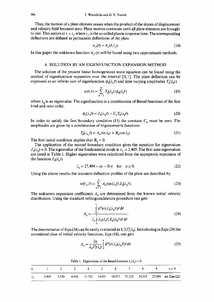
6. S O L U T I O N BY AN E I G E N F U N C T I O N EXPANSION M E T H O D
The solution of the present linear homogeneous wave equation can be found using the method of eigenfunction expansion over the interval [0, 1]. The plate deflection can be expressed as an infinite sum of eigenfunction ~b.(2.r-) and time varying amplitudes T.(2.t)
w(f, f) = ~ T.(2.f)q~.(2.f) (19) n = l
where 2 n is an eigenvalue. The eigenfunction is a combination of Bessel functions of the first kind and zero order.
~b.(2,r-) = Jo()~.f) + C. Yo(2.r- ). (20)
In order to satisfy the first boundary condition (15) the constant C, must be zero. The amplitudes are given by a combination of trigonometric functions
T.(2,1g) = A.sin 2.t + B.cos 2.t. (21)
The first initial condition implies that B. = 0. The application of the second boundary condition gives the equation for eigenvalues
Jo(2.) = 0. The eigenvalue of the fundamental mode is 21 = 2.405. The first nine eigenvalues are listed in Table 1. Higher eigenvalues were calculated from the asymptotic expansion of the function Jo(2.t).
2 , = 2 7 . 4 9 4 + ( n - 9 ) ~ for n_>9. (22)
Using the above results, the transient deflection profiles of the plate are described by
w(f 1, f) = ~ A.sin (2.f) Jo(2.f). (23) . = 1
The unknown expansion coefficients A, are determined from the known initial velocity distribution. Using the standard orthogonalization procedure one gets
1
w°(r) Jo (2 , f ) fd f A. = o (24)
1
2. ~ Jo(2.f) J0(2. f ) f d f 0
The denominator of Eqn (24) can be easily evaluated as 1/2j2(2.). Introducing in Eqn (24) the considered class of initial velocity functions, Eqn (16), one gets
2 A . - ~2~ iw°(r)Jo(2,r-) fdf (25) 2,J1(2,) o
Table 1. Eigenvalues of the Bessel function Jo(2.) = 0
n 1 2 3 4 5 6 7 8 9 n > 9
2. 2.405 5.520 8.654 11.792 14.931 18.071 21.212 24.353 27.494 see Eqn(22)

Large deformation of thin plates 907
The above integral has been evaluated for a particular case • =/3 which corresponds to the rectangular initial velocity profile. The result is
2r/~Jl(2"~) (26) A n - 42 2 • z, Jl(2,)
This completes the derivation of the solution in the loading range, i.e. for ~r > 0. As mentioned earlier, propagation of the unloading front, which leaves behind a permanently deformed plate, is governed by Eqn (17). In principle, it is possible to solve this equation, which is a product of two infinite series, numerically. The trajectory of the unloading wave t = t(f) could then be substituted into Eqn (23) to get the exact final deflection profile of the plate. In order to derive a closed-form solution, an approximate unloading condition is developed based on the notion of mode convergence [10, 11]. The velocity field, calculated from Eqn (23), is
w(Fl,f)= ~,, A,2.cos(2j)Jo(2,r-). (27) t l=l
It is seen that amplitudes of higher modes decay more rapidly than those of lower modes. The amplitudes of the nth mode vanishes when cos (2.f) = 0 or
f("~ = --~-~. (28) 22,
It is postulated that each mode contributes only up to the time f("~ and then this mode is switched off for the rest of the motion. Then, for later time only the first fundamental mode would persist. The amplitude of the first mode vanishes at
ft~) = f / = ~ = 0.653. (29)
The response time of the entire membrane is f/because at this point the velocity of all points vanishes simultaneously. Introducing Eqn (28) into Eqn (23) gives the following simple and elegant solution for the permanent plastic deformation of the plate
~f(f) = ~ A,Jo(2,f ). (30) n = l
One shortcoming of the above approach is that it provides a "sufficient" but not a "necessary" condition for unloading. As a result, the plate deflection profiles might not be realistic. Another disadvantage of the eigenvalue expansion solution is its slow convergence, Despite these deficiencies, the above approximate unloading criteria was applied with some success in Refs [16] and 1-17] to the problem of impulsively and pulse loaded cylindrical shells.
To illustrate the above procedure calculations were run for the special case of 7 =/3 taking a 40 term approximation. Figure 5 shows plots of normalised plate deflection ~f(f)/~s(0) for five values of loading radius parameter used in the experiment. The present solution does predict the effect of local bulging for small loading radii as well as global dishing for uniform impulse. However, the difference between the two bounding curves corresponding to
= 0.186 and ~ = 1.0 was much larger from that observed experimentally and shown in Fig. 4. Therefore, the parametric study of the solution based on switching off of subsequent modes was not pursued any further. Results of a similar study using the exact unloading criterion will be reported in a subsequent publication.
7. WAVE FORM SOLUTION (PHASE I)
An exact solution of the present initial-boundary value problem using the method of characteristics does not appear to have been reported in the literature. Such a solution is the

908 T. Wierzb ick i and G. N. Nur i ck
, 0 ~ ......................... ~..~!!!~,,,,::~.!.~,.=:::~.::~.~: .................................................................................................
i o.~ .................... \ ~ : : ......... :, ............. ~ . ~ . ~ . . . . . . . . . . . . . . . . . . . . . . . . . . . . . . . . . . . . .
~ 0 , 6 . . . . . . . . : "-.:. . . . . . . . . . . . . . . . . . . . . . . . . . . . ~ ............. ¢ . . . . . . . . . . . . . . . . . .
, :~,: :-, . . . . . . . . . . . . . . . . . . . . . . . . . . . . . . . ':~., . . . . . . . . . . . . . . . . . : . . . . . . . . . . . . . . . . ~, 0 . 5 -
0 . 4 -
"~ 0 , 3 -
0 . 2 -
= 0 . 1 -
0 0
-,. -.,. \ -.,
............................................................... i:~ ....... ?:~. . . . . . . . . . . . . . . . . . . . . "~, . . . . . . . . . . . . . . . " ' . ............ . "-,. \
l i i i - i l i i ,
0.1 0 .2 0 .3 0 .4 0 .5 0 .6 0 . 7 0 . 8 0 .9 Relative distance fronl plate centre
~ ratio-O.183--ratio-0.25 ..... ratio=0.33
ratio-0.40 ...... ratio-0.70 .... ratio-l. O0
Fig. 5. Pred ic t ion of no rmal i sed deflect ion profiles ca lcu la ted by means of the e igenvalue expans ion method.
subject of on-going research [18]. In this section, we shall present an approximate solution that uses some basic ideas of the plastic wave theory. Due to the discontinuities in the assumed initial velocity field [Eqn (11)], there will be two shock waves starting from the point t ' : a :
Diverging wave r = a + c t
Converging wave r = a - c t .
Therefore, ahead of the diverging wave the plate is undisturbed. Likewise, ahead of the converging wave the plate transverse velocity is constant and equal to V o. The central portion of the plate undergoes a rigid body motion. Between the converging and diverging waves there is a region of plastic deformation (Fig. 6). The velocity and displacement field are
L
t;i
0
i
I I I I I
~ , * - 2(~-
W= ~ '=0
r A a rB R
P h a s e II
t P h a s e I
Fig. 6. Phase d i ag ram wi th two shock waves o r ig ina t ing at r = a.
r

Large deformation of thin plates 909
governed by the wave Eqns (3) or (14). A transient velocity field in the deforming region is called the wave profile.
Rectangular initial velocity
It is assumed that in the deforming region the plate velocity varies with r (Fig. 7).
~(r, t) = V° 1 - a
for O < r < a - - c t
- - r ] for a - - c t < r < a + c t ct
for a + ct < r < R .
(31)
It can be shown that with the above wave form the total linear momentum of the plate is not conserved. However, Eqn (31) does satisfy velocity conditions ahead and behind of the shock waves. It also leads to simple calculations. Equation (31) is valid until the diverging wave reaches the support, a + ct = R, or the converging wave reaches the plate centre, a - ct = 0, whichever occurs first. Of interest is the limiting case when a = R/2 because both waves will reach, respectively, the plate centre and support at the same time, t I = R/2c. From this point on, the mode form solution takes over, as shown in the next section. When a ~ R /2 (or
~ 0.5), there is an intermediate phase of the plate response which makes calculations more difficult. Therefore, from this point on, the analysis is restricted to the loading radius equal or close to half of the plate radius (a ~ 0.5). The plate deflection is obtained by integrating Eqn (31) with respect to time
l
w(r, t) = ~ ~(r, t) dt. (32) 0
Note that time integration is performed along vertical trajectories (constant radius). As shown in Fig. 6, limits of integration are different for different regions of the plate. For a representative plate element, such as r a, in the interval 0 < r <a, there are two contributing regions to Eqn (32).
w ( r , t ) = ~ V o d t + ~ 1 dt. (331 o a r/c -~--J
Likewise, for the plate radius inside a < r < R /2 there is only one contributing region
w(r,t)= V o 1 + dt. (34) ( r - a)/c c t
It is assumed that a < R/2. Then the end of phase I motion is marked by the shock wave reaching the plate centre tl = a/c. Plate deflection at the end of phase I is denoted as w(r, tt) = wt(r).
The integrals (33) and (34) can be easily evaluated and the resulting deflection profile is:
i oF r a + ( a - r)ln for O < r < 2 a w l ( r ) = l ~ k - 2 (35)
for 2a < r < R.
C C
I t = 0 Vol
C C
Fig. 7. Initial and transient velocity profiles assumed in the wave form solution.
910 T. Wierzbicki and G. N. Nurick
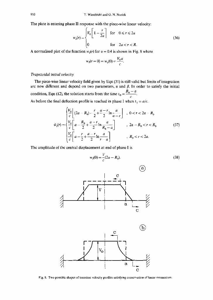
The plate is entering phase II response with the piece-wise linear velocity:
1 - ~ a for O<~r<~2a wt(r ) =
for 2a < r < R.
A normal ised plot of the function wr(r) for ~ = 0.4 is shown in Fig. 8 where
Voa w~(r = 0) = w~(0) =
c
(36)
Trapezoidal initial velocity
The piece-wise linear velocity field given by Eqn (31) is still valid but limits of integrat ion are now different and depend on two parameters , ~ and 13. In order to satisfy the initial
R b - a condit ion, Eqn (12), the solut ion starts f rom the t ime t o = - - -
c As before the final deflection profile is reached in phase I when tl = a/c.
a I (2a - Rb) -- ~ + ~ in a -- r '
tV_~ I R b a - r a 1 2 a - - R b < r < R b (37) ff1(r-) = a - -~- + ~ In Rb _ a '
r a r a 1 a - ~ + - - ~ - l n r _ a ' Rb<r<2a"
The ampl i tude of the central d isplacement at end of phase I is
wi(O) = -V(2a - Rb). (38) c
® C
C
® C
a L . C
Fig. 8. Two possible shapes of transient velocity profiles satisfying conservation of linear momentum.

Large deformation of thin plates 911
The normalised plate deflection obtained from Eqns (37) and (38) are
w / f ) =
wl(O)
f ~ m f 1 2(2~-tim) + 2 ( 2 ~ ) l n a - f , 0 < f < 2 ~ - f l
1 ~ - - f - - - - 2 ct - - f l < r < f l + 2(2~ --/3) In/3 _ ~
- - In_ , / 3 < f < 2 ~ . 2(2ct --/3) 2(2ct --/3) r --
(39)
N o n l i n e a r w a v e pro f i l e
As a next step of improving the present theory, a parabolic wave profile can be assumed in the plastically deforming region (see Fig.8).
ff(rlt ) = A ( t ) r 2 + B ( t ) r + c(t). (40)
The three unknown time-variable coefficients can be uniquely determined from the following conditions at the diverging and converging shock waves:
V o = A ( t ) ( a - ct) 2 + B ( t ) (a - ct) + c(t)
0 = A ( t ) ( a + c t ) 2 + B(t) (a + ct) + c(t). (41)
The third condition is the conservation of linear momentum. The complete solution of the above problem could be worked out with some complex algebra. The results will be presented in a forthcoming publication. Even though the local equation of equilibrium (3) will not be satisfied, the resulting velocity and displacement fields are believed to be a very good approximation to the exact (so far unknown) solution. Previous application of the principle of conservation of total linear momentum to the problem of projectile impact on an infinite plate has led to an excellent correlation with experimental data (Hoo Fatt and Wierzbicki [19]).
8. MODE SOLUTION (PHASE II)
Phase II motion lasts from the arrival time t I of the transverse wave at the plate centre to the termination of plate motion lf. It is characterized by a complex interaction of the incoming waves with reflected waves and the propogating unloading and reloading fronts. This stage of plate response can be conveniently studied by means of the mode approxi- mation technique, much in the same way as it was done by Symonds and Wierzbicki [10] for the entire duration of the motion. The approximate solution is taken to be the first term in the infinite series (19). The corresponding deflection function at the end of phase II:
~u(f) = AaJo(21F). (42)
The corresponding mode velocity at the beginning of phase II
WlI(fl [lI)= A 1/~ 1Jo( 21 r), (43)
should be compared with the normalised velocity at the end of phase I
E We(r, gt) = 1 -- ~ , 0 _< f_< 2~ (44)
2 ~ < f < 1.
According to Martin and Symonds [11] the criterion for the selection of the unknown amplitude A1 is the minimization of the kinetic energy "difference" A between these two

912 T. Wierzbicki and G. N. Nurick
velocity fields
1
A = m ~ [fin(r, t2) -- w1( f, f2)] 2 rdr. (45) 0
The condition, dA/dA 1 = 0 yields
1
~w1( f, fl ) Jo(21 f ) r dr A121 = o (46)
1
J 2(,~l r ) r dr 0
where el(f, t2) is given by Eqn (44). It can be noted that the form of the above expression is identical to the first term of the Fourier expansion of the initial velocity using the mode orthogonality property (24). This equivalence of a purely mathematical technique and a physically based procedure has never been noted in the literature.
The integral (46) involving Bessel functions can be evaluated in a closed-form. However, a good accruacy is obtained by approximating the Bessel function by the following power function:
Jo(21f) ~ 1 - ~3/2 (47)
which is plotted in Fig. 9. After straightforward calculations, the final form of the phase II response becomes
~1t(f) = 2.16r/c(2[1 _ 0.15~1.5](1 _ ~3/2) (48)
for the rectangular shape of the initial velocity. The dependence of the above stationary mode solution on the input parameter c( will be
discussed in the next section.
9. DISCUSSION
In the preceding section closed form solutions were derived for two distinct phases of the plate response. Some features of each individual phase will be discussed first. Thereafter the
a
w IB
E
z
1.0
0.9-
0.8-
0.7-
0.6-
0.5-
0.4-
0.3-
0.2-
0.1
0.0 0.0
.............................................. P;se II (Eqn 46)
Phase I (Eqn 34) ..................
o11 o:2 ola o.'4 0:5 o16 o:r o18 Normal i led Radius
Fig. 9. Normalised displacement profile at end of phase I.
"\x x
o19 11o

Large deformation of thin plates 913
solution for the final plate deflection will be plotted and analysed in the special case of~ = ft. A more general case a ¢ fl is discussed in Section 10. The phase I solution clearly shows a central bulge of radius r = a produced by the transient phase of deformation. An interesting feature of the present solution with ~ -- fl is that the slope of the deflection profile at r -- 0 is infinite. According to Eqn (1), this means that the tensile radial strains at this location would be infinite. The plate would instantly rupture at r -- a by developing tensile necking, independent of the value of the applied imputse. The fact that, in reality, a "delayed" rupture deformation is observed only at certain high critical initial velocity ~,(or critical impulse), or no rupture of the central disc occurs, can be explained by two facts. First, the two-dimensionality of the axi-symmetric, deformation process and the presence of in-plane displacement u are inhibi- ting neck formations in the central region. More importantly, complex physics of the burning process produces a more smooth initial velocity distribution. This will tend to reduce the slope at r = a and bring the theoretical deflection profile closer to reality.
This aspect of the response will be discussed at more length in the next section. Phase II motion is characterised by the constant shape of the velocity, displacement and
acceleration profiles with a time-varying amplitude. The accuracy of the solution depends how close the velocity profile at the end of phase I matches the mode shape profile ~b(f). In the most ideal c a s e , Al~.l/go = 1, and the "difference" kinetic energy A = 0. This is not possible with the ~l(f) linear in ~. However, it is seen from Eqn (48) that Eqn (45) which is the measure of accuracy, A is an increasing function of the loading radius parameter ~. It attains the highest value at the limit of validity of the present phase I solution ~t -- 0.5. Therefore, best results are expected for ~ equal or slightly smaller than the critical value and results will be plotted for two values of the loading parameter, ~ -- 0.5 and ct = 1. Note, that for ~ -- 1 there is no phase I motion and the plate response is dominated by phase II.
The permanent deflections of the plate is the sum of phase I and phase II contributions:
~s(r~ = ~1(r-) + ~u(r) (49)
where ~ ( f ) and ~u(f) are given respectively by Eqn (35) and Eqn (48). The central plate deflection is:
#s(0) = r/[a + 2.16a2] (50)
where the small term - 0.15a 1"5 in the square bracket of Eqn (48) is neglected. From the above result it is seen that both phases of motion contribute equally to the permanent central deflections when the load radius parameter is approximately c~ = 0.5. From Eqns (49) and (50) the final expression for the normalised deflection profile is:
~f(f) :t [ f a J_~ 2"16a2 ~1.5) (51) wI(0) ot+2.16ct2 ~ t - ~ + ( ~ - f ) l n ~ a + 2 . 1 6 ~ i ( 1 -
where the contribution on the first term extends only over 0 < f < 2cc The effect of the loading radius on the normalised deflection profile is shown in Fig. 10. A good qualitative agreement with the trend of experimentally deflected shape, presented in Fig. 4 is observed. For a quantitive agreement, the effect of the burning phase must be considered.
10. C O R R E C T I O N FOR THE B U R N I N G PHASE AND EXPERIMENTAL VERIFICATION
No attempt was made in the present paper to correlate the predicted and measured maximum permanent plate deflection. Such as correlation was made by Symonds and Wierzbicki [ 10], giving generally very good results. However, an interesting observation can be made by comparing the present solution to that of Symonds and Wierzbicki. Converting Eqn (50) to physical quantities according to Eqns (12) and (13) and using the correction factor for the conservation of linear momentum, given by Eqn (40), one gets
w,(0) = 1;---- [0.28 R + 0.51]. (52) hRx/ ptro L a J

914 T. Wierzbicki and G. N. Nurick
1.0
A
o o~
,,$
.2 q I= Z
0 , 9 -
o8"
0.7-
0.6-
0.5-
0.4-
0 .3
0.2-
0.1
0.0 0.0
....... ;~'?~2~,..~ "%%
0.'1 012 ola 014 015 0;6 017 018 019 1.0 Norma l i sod Rad ius ~ = r/FI
Fig. 10. Effect of the loading radius parameter ~t on the normalised permanent plate deflections.
In Ref. [10], the mode approximation was used (phase II only) and the solution for w I was shown to have the same functional form except a difference in the coefficient. Taking ct = a / R = 0.5 Symonds and Wierzbicki obtained 0.41 for the value of the proportionality constant. At the same time Eqn (52) predicts 0.28(R/a)+ 0.51 = 1.07, which is more than twice as large. This suggests that phase I of transient motion may in reality be much shorter or not exist at all.
The above assertion is supported by two independent observations. All test pieces used in the present series of experiments have shown a distinct burn radius R b, which was consider- ably larger than the radius (a) of the explosive disc. Details of the measurements of the burn radius R b ---Rb(a ) will be reported in the forthcoming publication [20]. This is a clear indication that the impulsive loading is distributed more smoothly along the plate radius. A hypothetical profile of the initial velocity is sketched in Fig. 11. The assumption of a uniform impulse resulting from a uniformly thick sheet of explosive, which goes back to the experimental work by Florence [21] is shown to be incorrect for partially loaded plates.
In the on-going work, the commercial code ABAQUS was used to find such distribution of initial velocity that gives best correlation with experimental maximum deflection and deflection profile. The results of preliminary calculations show that the best agreement is obtained with radially varying initial impulse (Bimha [22]). In view of the above discussion
I
I Fig. 11. Discontinuous rectangular profile of initial velocity and actual continuous profile.

Large deformation of thin plates 915
the correlation of the deflection profile predicted by the present solution with the experimen- tal data is performed for a trapezoidal initial velocity, which is more realistic.
The effect of the burning radius on the normalise phase I deflection profile, calculated from Eqn (39) is shown in Fig. 12 for a chosen loading radius ~ = 0.5. It is seen the slope at r = 0.5 becomes now finite for fl > 0.5. A comparison of the theoretical and experimental deflection profile for ~ = 0.4 is shown in Fig. 13, where the dimensionless burn radius is assumed to be fl = 0.6. At these values approximately 30% of the maximum central deflection occurs in the transient phase. The contribution of the modal phase is 70%. The agreement is seen to be generally good, in particular for the loaded area, which gives credibility to the present approximate methods. A uniformly distributed impulse over the plate, ~ = 1, gives only phase II response. Here the agreement between the experiment and theory is excellent, see Fig.14.
1.0
0 , 9 - A
o.8-
~" 0.7-
0.6- O R
0.5-
a 0.4-
. o 0.3- i a E 0.2-
Z 0.1-
0.0 0.0 011 0'.2 013 014 015 016 017 Normalised Radius ~ = r/R
l~ = 0 . 6 ~ ~
# = 0 . 7 ~
= 1.0
= 0 . 9
~ = 0 . 8
i I
0.8 0.9 1.0
Fig. 12. Effect of the burning radius parameter fl on the phase I normalised deflection profiles for ~ = 0.5.
1.0
0.9-
0.8-
~" 0.7-
c 0.6- 0 o • 0.5-
I
a 0.4-
.= 0.3- I
E 0.2-
z 0.1-
0.0
~ = 0 . 4
,,. p = O , 6 ,
I F i I i t I ]
0.0 0.1 0.2 0.3 0.4 0.5 0.6 0.7 0.8 0.9 1.0 Normalised Radius ~ = r/R
Fig. 13. Compar ison of experimental and theoretical deflection profiles for ct = 0.4 and fl = 0.6.

1.0
....... ,,, = 1.0
__ ~ i r n e n t a l , Ref(6)
0,9"
0 . 8 -
0 . 7 -
0 . 6 -
-- 0.5-
0,4-
0.3-
~ .2
Z 0.1-
916 T. Wierzbicki and G. N. Nurick
0.0 o.o o11 o12 0;3 o.'4 ols o.'6 o17 o;6 o19 1.o Normallaed Radius ~ = r/R
Fig. 14. Comparison of experimental and theoretical deflection profiels for 7 = 1.0.
There are two additional physical factors which produce a non-uniform distribution of initial velocity in centrally loaded plates. One is the stand-off distance H produced by the padding foam. The other is the finite burning speed of the explosive material, which is estimated to be Cb = 7500 m/sec. The exact determination of the dynamic pressure variation in the present problem would require solution of the gas dynamic equations. This is clearly beyond the scope of the present paper. However, it is relatively easy to calculate an additional plate bulging occurring during the burning process. Assuming an incident spherical wave on the plate with the speed Cp, the additional plate deflection during the initial momentum transfer phase is (see Fig. 15).
wb(r) = ~ [ ~ n - ~ + a 2 - ~ + r2]. I53)
Because the burning speed is some 30 times larger than the plastic transverse wave speed in the plate, the contribution of Eqn (53) to the overall permanent plate deflection is negligible.
11. CONCLUSIONS
I I i
_ Ot _ 1
, C t
Fig. 15. A spherical wave produced by a burning explosive initiating at the point of detonation and the resulting localised bulging.
Large deformation of thin plates 917
The present series of tests provided a wealth of data on deformation and failure of thin mild steel membranes subjected to the central impulsive loading. The most interesting conclusion from the experimental part of the work is that there are two distinct failure modes of plates. One is a formation of a disc with a diameter slightly larger than the diameter of the centrally placed sheet of explosive. The "discing" failure, associated in the past with the projectile impact problems, is preceded by considerable tensile necking in the radial direction. The second failure mode is the tensile/shear tearing fracture at the clamped edge. It was found that a transition between these two failure modes depends on the loading radius.
A long-range goal of this research is to predict the magnitude of the critical impulse to failure and the location of the onset of failure in the plate. The immediate objective of the present work was to develop a simple analytical technique for calculating transient and final deflection profiles of plates. This would open the way for a precise calculation of strains within the plate that govern neck formation and eventual rupture of thin plates. Two solution techniques were devised to solve the initial-boundary value problem for the wave equation in the polar coordinate system. The eigenfunction expansion method is quite general but its application is restricted by the nonlinear unloading criteria which precludes a closed-form solution. The wave form solution holds a great deal of promise because it gives an insight into the physics of the transient plate motion and leads to relatively simple algebra. The plate response was divided into the transient phase and the mode phase. Closed-form solutions were derived for the maximum permanent plate deflections and deflection profiles for different sizes of the central loading area. When attempting to correlate the present theoretical results with experimental data, it was immediately recognised that the impulsive loading cannot be uniformly distributed over the inner radius a. The final conclusion drawn from the present study is that the initial impulse is dispersed near the loading edge r = a. In other words, there is gradual transition from a uniform impulse around the axis of symmetry to zero at r = R b, outside the loading zone. It was shown that a good correlation with the measured profile is obtained when the above transition zone is taken into account. The results of this study have set a clear task for the next step of research i.e. to find the initial velocity distribution resulting from an explosion to get the best correlation with test results. The result of such a study will be reported in a forthcoming publication where, in addition to the approximate wave from solution, the method of characteristics and numerical methods will be used.
Liu and Stronge 1-23] have recently derived a closed form solution of plates subjected to a central pressure pulse. The solution was based on small deflection theory of plates with shear and bending resistance. No comparison with the test results was offered.
Acknowledgement--The work reported herein has been partially supported by the Foundation for Research and Development (FRD) of the Republic of South Africa and the Department of Ocean Engineering of the Mass- achusetts Institute of Technology. Both sources are gratefully acknowledged. The authors are indebted to Dr Mihaela Mihailescu-Suliciu for elightening discussions on the wave propagation solution. We are most grateful to Mr Richard Bimha for performing time-consuming computer calculations of the eigenfunction expansion solution. Finally thanks are due to Mrs Dawn Beckett, Mrs Diann Donald and Mr Krys Zacny for their help in the technical preparations of the manuscript.
REFERENCES
1. Nurick, G. N., Martin, J. B., Deformation of thin plates subjected to impulsive loading--a review, Part I: theoretical considerations. International Journal of Impact Engineering, 1989, 8 (2), 159-170.
2. Florence, A. L~Resp~nse~fcircu~arp~atest~centra~pu~se~ading.~nternati~nalJ~urnal~fS~lidsStructures~975` 13, 1091-1102.
3. Ghosh, S. K. and Weber, H., Experimental-theoretical correlation of impulsively loaded axiasymmetric rigid- plastic membrane. Mechanics Research Communications, 1976, 3, 423 428.
4. Bodner, S. R. and Symonds, P. S., Experiments on viscoplasticresponseofcircularplates toimpulsiveloading. Journal of Mech. Phys. Solid~, 1979, 27, 91-113.
5. Nurick, G. N. and Martin, J. B., Deformation of thin plates subjected to impulsive loading--a review, part II: experimental studies. International Journal of Impact Engineering, 1989, 8 (2), 17 l - 186.
6. Teeling-Smith R. G. and Nurick, G. N, The deformation and tearing of circular plates subjected to impulsive loads. International Journal of Impact Engineering, 1991, l l (1), 77 92.

918 T. Wierzbicki and G. N. Nurick
7. Baker, W. E., Approximate techniques for plastic deformation of structures under impulsive loading, Shock Vibration Digest, 1975, 7 (7), 107-117.
8. Duffey, T. A., The large deflection dynamic response of clamped circular plates subject to explosive loading. Sandia Laboratories Research Report No. SC-RR-67-532, 1967.
9. Jones, N., Impulsive loading of a simply supported circular rigid-plastic plate. Transactions of the ASME, Journal of Applied Mechanics, 1968, 35, 59 65.
10. Symonds, P. S. and Wierzbicki, T., Membrane mode solution for impulsively loaded circular plates. Journal of Applied Mechanics, 1979, 46, 58-64.
11. Martin, J.B. and Symonds, P.S., Mode approximations for impulsively loaded rigid-plastic structures. Proceedings of the ASCE 92 ( EMS), 1966, 43-66.
12. Chon, C. T. and Symonds, P. S., Large dynamic deflection of plates by mode method. Journal of Engineering Mechanics Div., Proceedings of the ASCE, 1977, 103, (EMI), 3-14.
13. Symonds, P. S. and Chou, C.T., Finite viscoplastic deflection of an impulsively loaded plate by the mode approximation technique. Journal of Mech. Phys. Solids, 1979, 27, 115-133.
14. Beynet, P. and Plunkett, R., Plate impact and plastic deformation by projectiles. Experimental Mechanics, 1971, 11, 64 70.
15. Lippmann, H., Kinetics of the axisymmetric rigid-plastic membrane subjected to initial impact. International Journal of Mechanical Sciences. 1974, 16, 297-303.
16. Hoo Fatt, M., Wierzbicki, T., Moussouros, M. and Koenig, J., Rigid-plastic approximation for predicting plastic deformation of cylindrical shells subjected to dynamic loading. Shock and ~bration, 1996, 3 (3), 169-181.
17. Hoo Fatt, M., Plastic Deformation of an Infinitely Long Ring-Stiffened Shell subjected to Blast loading. Submitted to Quarterly Journal of Mechanics and Applied Mathematics.
18. M ihailescu-Suliciu, M., Private communication 1996. 19. Hoo Fatt, M. and Wierzbicki, T. Deformation and performation of circular membrane due to rigid projectile
impact. In Proceedings of the Symposium on the Dynamic Response of Structures of High-Energy Excitation, P VP, Dec 1-6, 1991, 225, ASME Winter Annual Meeting, Atlanta, Georgia, pp. 73-83.
20. Nurick, G. N. and Radford, A. M., The response of circular plates subjected to concentrated blast loads. (In preparation.)
21. Florence, A. L., Circular plates under a uniformly distributed impulse. International Journal of Solids Structures, 1966, 2, 37 47.
22. Bimha, R., Private communication 1996. 23. Liu, D. and Stronge, W. J., Shear and bending deformation of rigid-plastic circular plates by central pressure
pulse. International Journal oflmpact Engineering, 1996, 18 (4), 383-402.


![A Discrete Model for Inelastic Deformation of Thin Shellsmrl.nyu.edu/~dzorin/papers/secord2004sds.pdf · A Discrete Model for Inelastic Deformation of Thin Shells ... [COPar] use](https://static.fdocuments.in/doc/165x107/5aa7093d7f8b9aee748b8aaa/a-discrete-model-for-inelastic-deformation-of-thin-dzorinpaperssecord2004sdspdfa.jpg)