Large Area Multi-stacked Lithium-ion Batteries for ...
9
Large Area Multi-stacked Lithium-ion Batteries for Flexible and Rollable Applications Journal: Journal of Materials Chemistry A Manuscript ID: TA-ART-01-2014-000551.R1 Article Type: Paper Date Submitted by the Author: 21-Feb-2014 Complete List of Authors: Kim, Joo-Seong; Korea Advanced Institute of Science and Technology, EEWS Lee, Yong-Hee; Korea Advanced Institute of Science and Technology, EEWS Lee, Inhwa; KAIST, Mechanical Engineering Kim, Taek-Soo; KAIST, Mechanical Engineering Ryou, Myung-Hyun; Hanbat National University, Choi, Jang Wook; Korea Advanced Institute of Science and Technology, EEWS Journal of Materials Chemistry A
Transcript of Large Area Multi-stacked Lithium-ion Batteries for ...
Large Area Multi-stacked Lithium-ion Batteries for Flexible
and Rollable Applications
Journal: Journal of Materials Chemistry A
Manuscript ID: TA-ART-01-2014-000551.R1
Article Type: Paper
Date Submitted by the Author: 21-Feb-2014
Complete List of Authors: Kim, Joo-Seong; Korea Advanced Institute of Science and Technology, EEWS Lee, Yong-Hee; Korea Advanced Institute of Science and Technology, EEWS Lee, Inhwa; KAIST, Mechanical Engineering Kim, Taek-Soo; KAIST, Mechanical Engineering
Ryou, Myung-Hyun; Hanbat National University, Choi, Jang Wook; Korea Advanced Institute of Science and Technology, EEWS
Journal of Materials Chemistry A

Journal of Materials Chemistry A RSCPublishing
PAPER
This journal is © The Royal Society of Chemistry 2014 J. Name., 2014, 00, 1-3 | 1
Cite this: DOI: 10.1039/x0xx00000x
Received 00th January 2014,
Accepted 00th January 2014
DOI: 10.1039/x0xx00000x
www.rsc.org/
Large Area Multi-stacked Lithium-ion Batteries for
Flexible and Rollable Applications†
Joo-Seong Kim‡a
, Yong-Hee Lee‡a
, Inhwa Leeb, Taek-Soo Kim
b, Myung-Hyun
Ryouc* and Jang Wook Choi
a*
The demand on flexible lithium ion batteries (LIBs) is successively increasing for timely
advent of various flexible mobile electronic devices. Along this direction, a vast number of
smart approaches such as implementation of conductive nanomaterials onto paper and textiles
have been recently demonstrated. Most of them were, however, limited to single-cell levels. In
the present study, in an attempt to expand the knowledge and design accumulated in the single-
cell levels to larger-scale applications, large area flexible battery modules were developed.
Multi-staking configuration was adopted for high areal energy density in each single-cell,
while textile-based electrodes on both sides grant mechanical stability even in the module
levels by efficiently releasing the stress generated during aggressive folding and rolling
motions. Moreover, the connection and stacking of the single-cells give wide tuning
capabilities in the overall voltage and capacity of the module. The current battery design
should be immediately applicable to a broad range of outdoor, building, and military items.
Introduction
Lithium ion batteries (LIBs) have played a central role in wide
propagation of mobile electronics into our everyday lives1-5. The
successful fulfilment of LIBs as power sources has led to the birth of
novel forms of portable electronic devices such as touch pads, e-
book, and smart watches, and such trend of creating new conceptual
devices and relevant markets is expected to continue. On the other
hand, beyond simply serving as power supplies, LIBs are currently
required to possess unconventional physical properties to keep pace
with upcoming flexible and wearable electronic applications6-11.
To meet this new demand, considerable research efforts have
been invested to develop flexible and wearable LIBs based on new
aGraduate School of Energy, Environment, Water, and Sustainability (EEWS) and
Center for Nature-inspired Technology (CNiT), KAIST Institute NanoCentury,
291 Daehakro, Yuseong-gu, Daejeon 305-701, Republic of Korea. E-mail:
bDepartment of Mechanical Engineering, Korea Advanced Institute of Science
and Technology (KAIST), 291 Daehakro, Yuseong-gu, Daejeon 305-701, Republic
of Korea.
cDepartment of Chemical and Biological Engineering, Hanbat National
University, Deokmyoung-dong, Yuseong-gu, Daejeon 305-719, Republic of
Korea. E-mail: [email protected]
† Electronic supplementary information (ESI) available: Fig. S1-S2, Video S1,
S2.
‡ Equal contribution.
cell designs12-16. Along these directions, one of the most effective
strategies is implementation of paper17-19 and textiles20, 21 as current
collectors in lieu of conventional metal foil because inherent three-
dimensional (3D) fibrous structures in paper and textiles can
dissipate the stress generated during folding and bending motions of
the battery assemblies. The intrinsic insulating nature of the paper
and textiles were overcome by conformal coating of conductive
carbon nanomaterials including carbon nanotubes22-24 and graphene25,
26 or traditional electroless metal deposition27. Other cell components,
such as separator and electrode binder, which could affect successful
achievement of such unconventional battery properties, have also
been carefully investigated28, 29.
Although the aforementioned demonstrations represent
substantial progresses in the flexible/wearable battery research, most
of the previous outcomes have been to the proof-of-concept levels
limited to small areas within single-cell levels30-32. In the present
study, having noticed such limited situation, we have expanded the
textile batteries into large area multi-stacked platforms to cover
emerging outdoor, building, and military applications. Detailed
target items include tent, sleep bag, curtain/blind, curvy roof/eave,
parasol, military jacket, military heating glove, multifunctional
military goggles, etc. Moreover, the demonstrated module consisting
of multiple single-cells is allowed to deliver wider ranges of the
operation voltage and total capacity while maintaining bending and
rolling capabilities, suggesting novel opportunities to tune the key
battery parameters based on the cell design in both single-cell and
module levels.
Experimental section
Page 1 of 8 Journal of Materials Chemistry A

PAPER Journal of Materials Chemistry A
2 | J. Mater. Chem., 2014, 00, 1-3 This journal is © The Royal Society of Chemistry 2014
Electroless nickel deposition
The nickel (Ni)-coated loosely-woven and finely-woven textiles
were prepared based on the commercial procedure reported
previously27. Briefly, polyester fabric was dipped in 37%
hydrochloric acid (HCl) solution containing 26 mM tin chloride
(SnCl2) for 10 min at 25 ºC for cleaning. For the textile
activation, the samples were immersed in the solution
containing 1.7 mM palladium chloride (PdCl2), 37% HCl, and
0.32 M boric acid (H3BO3) at pH=2. Next, for electroless nickel
deposition, the fabric samples were dipped into an aqueous
solution containing 97 mM nickel sulfate (NiSO4), 27 mM
trisodium citrate dihydrate (Na3C6H5O7⋅2H2O), 0.34 M
ammonium chloride (NH4Cl), and 0.14 M sodium
hypophosphite monohydrate (NaH2PO2·H2O) for 30 min.
Finally, the nickel-deposited fabric was washed with deionized
water and dried at 150 °C for 20 min. The final Ni thickness
was approximately 180-200 nm.
Synthesis of polyurethane binder
Polyurethane (PU) binder was synthesized according to the
following procedure27: 4,4-diphenylmethane diisocyanate
(MDI, 0.12 mmol), polytetramethylene glycol (PTMEG, 0.03
mmol), and polyethylene glycol (PEG, 0.03 mmol) were
dissolved in 1 L of N,N-dimethylformamide (DMF), and then
stirred for 5 h at 80 ºC to generate a well-mixed pre-polymer
emulsion. Next, 0.06 mmol 1,4-butanediol was added to the
pre-polymer emulsion, and the emulsion was then stirred again
for 5 h at 80 ºC for further polymerization into the final
polymer form. For use of PU as a binder, the final polymer
emulsion was completely dried in a vacuum oven for 48 h at 70
ºC, and the dried polymer was dissolved again in N-methyl-2-
pyrrolidone (NMP).
Characterization
Tensile tests were conducted to examine the stretchability of
the Ni-coated textiles using a high-precision micromechanical
test system (Delaminator Adhesion Test System; DTS
Company, Menlo Park, CA, USA) with a customized jig.
Various kinds of the textile electrodes and polymer films were
cut into rectangular pieces with a length of 36 mm (or 21 mm
only in the cases of PU films) and a width of 3 mm and were
then stretched at a constant displacement rate of 20 µm s-1 until
fracture of the specimens occurred. All of the fracture
behaviours and electrical property changes during the pulling
motions were recorded by an optical microscope (VHX-1000,
Keyence, Osaka, Japan) and a multi-meter with four-point
probes (Keithley 2000), respectively. Peel strength tests were
also performed to measure the adhesion/cohesion strengths of
the electrodes using the same micromechanical test system as
the tensile tests. The specimen fabrication was conducted by
cutting the electrode samples into the pieces with a size of 10 x
30 mm2 (width x length), which were later attached to 3M
tapes. By pulling the tapes at a constant displacement rate of
100 µm s–1, the applied load was continuously monitored and
the peel strength-displacement plots were attained. The Gurley
number of the PU separator, defined as the time required for
100 cm3 of air to pass through the membrane under an air
pressure of 0.05 MPa, was out of the measurement range,
indicating almost no porosity of the PU separator. But, the Li
ionic conductivity was not hindered by good wettability of the
PU separator through its hydrophilic domains as described
previously27.
Cell preparation
Active electrodes were prepared based on the following
procedure: the active materials, denka black, and the PU binder
solution were dispersed in NMP in a weight ratio of 80:10:10
for both cathodes and anodes. Commercial lithium iron
phosphate (LiFePO4 or LFP, Hanwha chemical) and lithium
titanium oxide (Li4Ti5O12 or LTO, POSCO ESM) were used as
active materials of the cathodes and anodes, respectively. The
well-mixed slurries were cast onto the Ni-coated polyester
textiles by the doctor blade method. In each single-cell, the
mass loadings of the active materials were 205 and 215 mg for
the cathode (two layers) and anode (one layer), respectively, for
an active area of 5 x 5 cm2. The n/p ratio, defined as the actual
anode capacity/the cathode capacity, was adjusted to 1.12 for
the LTO/LFP full-cells. The electrochemical performances
were characterized by preparing aluminum pouch full-cells
(pouch size=10 x 11.5 cm2). In these cells, PU separators
(thickness=150 µm)27 and 1 M lithium hexafluorophosphate
(LiPF6) dissolved in a mixture of ethylene carbonate (EC) and
dimethyl carbonate (DMC) (EC/DMC=1:1=v/v, PANAX
ETEC) were used as separators and electrolyte, respectively.
The entire cell assembly was done in an argon-filled glovebox.
Electrochemical measurements
The electrochemical measurements were performed in the full-
cell potential range of 0.6~2.4 V (single-cell) and 2.4~9.2 V
(module) using a battery cycler (MACCOR series 4000). In
each cycle, the charging and discharging processes were
performed under CC & CV (limit current=0.1C) and CC
modes, respectively. Also, in this study, the C-rate was defined
based on the 1C value in each cell case, not actual
charge/discharge durations. The electrochemical folding-
unfolding tests were characterized by using a home-built linear
stage machine (QS48, TPC motion).
Result and discussion
Fig. 1a shows how each single-cell obtains flexible and rollable
capability. While each cell adopts the conventional stacking
configuration in assembly of the electrodes and separator, the
textile platforms in both electrodes distinguish the current
single-cells from the conventional counterparts based on metal
foil current collectors because 3D fiber networks inherently
existing within the textiles can release the stress during folding
and bending occasions and thus recover the original electrode
structures persistently. In order to endow the conductivity with
the given textile polyester in our case, Ni was coated on the
textile by means of the established electroless deposition (see
the Experimental section). A typical sheet resistance of the Ni-
coated textile was ~0.35 Ω sq-1, which is approximately 2~3
orders of magnitude lower than those based on the widely
adopted dip coating of carbon nanomaterials. This far superior
electronic conductivity is noticeable especially for the present
large area cells because poor conductivity could restrict the
increase in the cell area.
Page 2 of 8Journal of Materials Chemistry A

Journal of Materials Chemistry A PAPER
This journal is © The Royal Society of Chemistry 2014 J. Mater. Chem., 2014, 00, 1-3 | 3
The connection of the single-cells gives additional degrees
of freedom in the module design. For example, the connection
in series could increase the operation voltage, whereas the
connection in parallel could increase the overall capacity. Fig.
1b displays how 16 single-cells are connected in series to add
up the voltage. Based on the active materials (LFP and LTO)
chosen, each single-cell delivers 1.8 V, and the entire module
consisting of 16 single-cells thus delivers 28.8 V. In addition,
Fig. 1a, 1c, and 1d conceptually show representative items,
namely electronic display, outdoor tent, and window blind,
respectively, to which the current large area textile batteries are
applicable. In the IT area, the flexible and foldable
characteristics in the module level allow the current textile
batteries to be integrated onto emerging flexible displays and
could thus play a role in bringing the ubiquitous electronics to a
reality. Similarly, for the outdoor tents, the textile batteries can
be attached onto one of the curved tent sides and can thus be
folded together when the main body of the tent is folded (Fig.
1c right). Also, the rollable characteristic of the textile battery
module allows its entire body to follows the roller blind even
when rolled into the roll at the end of the blind (Fig. 1d). These
textile batteries could be combined with flexible solar cells in
the purpose of efficient energy saving for buildings when
installed in a way that the solar cells and textile batteries are
attached on the opposite sides of the blind.
The application range of the current textile battery module
could be varied depending on its energy density that is
determined by the total capacity and operation voltage. One of
the well-known strategies in increasing the total capacity is
multi-stacking of the given electrodes. To adopt such multi-
stacking approach, in the assembly of each single-cell, two
sheets of the cathode textile were stacked on both sides of the
anode textile with the separators sandwiched in between, as
shown in Fig. 2a. Notably, the use of both sides of the anode
textile was enabled by the 3D fibrous network structure in the
anode textile that allows for Li-ion diffusion in both directions.
Each single-cell delivers ~1.8 V based on the given pair of the
electrodes, LFP and LTO, and ~25 mAh for the given area of 5
x 5 cm2. This capacity value is indeed approximately doubled
as compared to that based on the single-stack approach27
employing the same cell preparation. The basic module in this
study is composed of 4 double-stacked single-cells, and thus
delivers 7.2 V, as displayed in Fig. 2b.
Flexible batteries should preserve electrochemical
performance even during aggressive folding and bending
motions. In particular, multi-stacking cells could experience
enhanced strains from their greater thicknesses and should thus
have better tolerance against such physical motions. In typical
bending/folding motions, a different level of strain tends to be
exerted onto each component layer across the cell stack, as
depicted in Fig. 3a. For instance, in our case, when an
aggressive folding was applied such that the folding angle
reaches 160º, the outer and inner cathode layers are calculated
to exercise 26% tensile and 19% compressional strains with
respect to the middle anode layer, respectively (See Fig. S1†).
In order to assess whether the Ni-coated textile can endure
these tensile/compressional strains, the microstructure of the
prepared Ni-coated textile was visualized during the given
strain conditions (Fig. 3b). From these images, it was confirmed
that the 3D porous network within the textile can afford to
accommodate the given compressional/tensile strains by
modifying the pore shapes. By contrast, conventional
aluminium foil was ripped off even after a 1% tensile strain was
Page 3 of 8 Journal of Materials Chemistry A

PAPER Journal of Materials Chemistry A
4 | J. Mater. Chem., 2014, 00, 1-3 This journal is © The Royal Society of Chemistry 2014
applied (Fig. 3b right). The superior tolerance against the
tensile motion was quantitatively verified in load-elongation
curves (Fig. 3c). In the case of aluminum foil, the tensile stress
generated turned out to be over six times as large as that of the
Ni-coated textile, and the tensile tolerance was even less than 1%
elongation, which is consistent with the optical microscope
characterization in Fig. 3b. As shown in Fig. 3d, the film
conductance of the Ni-coated textile remained preserved until
the strain reached as high as 40%. After the elongation
surpassed ~40%, the conductance dropped abruptly because the
crossed yarns began to be untangled. The tolerance against
compressional/tensile strains could be further enhanced if
thinner textiles were chosen because the strain is directly
related to the cell thickness as indicated by the equation in Fig.
S1†.
The tolerance against various strains could also be varied
depending on the weaving structure of the textile. In an attempt
to see the weaving structure dependence, two types of the
textile were tested: a loosely-woven one and a finely-woven
one. For reference, the threads in the textile are divided into
warp threads (vertically oriented) and weft threads (horizontally
oriented), and the density of the threads in each orientation is
described by the number of threads per inch: ends per inch
(EPI) for warp and picks per inch (PPI) for weft. The EPI and
PPI of the loosely-woven textile in our study were 110 and 92,
respectively, whereas those of the finely-woven textiles were
260 and 190, indicating that the thread density of the finely-
woven textile is about 2.21 times higher. Figs. 4a and b show
optical microscope images at various elongation ratios from 0
to 36% for the loosely-woven textile without and with the LFP
electrode components cast on top (5 mg cm-2), respectively.
Figs. 4c and d are the same cases but based on the finely-woven
textile. These two different types of the textiles exhibited
Page 4 of 8Journal of Materials Chemistry A
Journal of Materials Chemistry A PAPER
This journal is © The Royal Society of Chemistry 2014 J. Mater. Chem., 2014, 00, 1-3 | 5
conspicuously distinct behaviours in their tolerance against the
elongation. In the case of the loosely-woven textile, the
electrode film remained adhered all the way until 36%
elongation, whereas the electrode film on the finely-woven
textile peeled off after 18% elongation. In order to understand
these distinctive behaviours, it is instructive to see how the
textile releases the tensile stress. Upon tensile stretch, the
textile releases the stress by aligning warp and weft threads in a
direction where the angle between both threads decreases. In
this angle adjustment process, the finely-woven textile
generates higher stress, which could surpass the areal adhesion
force of the electrode film. For this reason, the electrode film
adhesion is more vulnerable for the case of the finely-woven
textile. The microscopic structural changes shown in Figs. 4b
and d were also recorded as video files (Video S1† and S2†,
respectively) during continuous elongation.
Figs. 4e and 4f are the load vs. elongation curves for both
types of the textiles. In both curves, it was observed that once
the electrode films were coated on the textiles, the load values
increased because the electrode films exert some stress against
the tensile motions of the textiles. Furthermore, the curve in Fig.
4f shows load-lagging behaviors at multiple points during the
elongation (Fig. 4f inset), which reflects the peel-off of the
electrode film.
The distinct adhesion of the electrode film, in turn, signifies
the crucial role of the polymeric binder in the electrode
components. In the present investigation, a PU binder was
employed instead of the conventional polyvinylidene fluoride
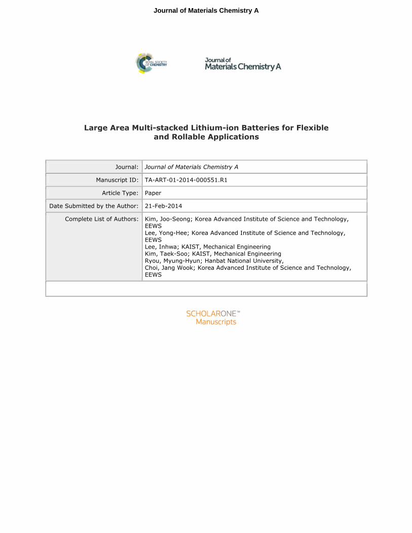
(PVDF) binder. Fig. 5a exhibits the peeling strengths of both
binder cases and reveals that the adhesion of the PU electrode
film is 3~4 times stronger than that of the PVDF electrode
counterpart. Furthermore, the results from the tensile stress tests
of pure binder films showed totally distinguishing properties
between both binders (Fig. 5b). The PVDF binder film
fractured only after 15% elongation, whereas the PU binder
film never fractured even at the elongation limit of the
instrument, 980%. The exerted stress during the given tensile
tests was also ~680 times smaller for the PU binder film. The
superior adhesion and the more elastic nature of the PU binder
indicate its suitable character for flexible batteries that are
required to sustain during a variety of aggressive physical
motions.
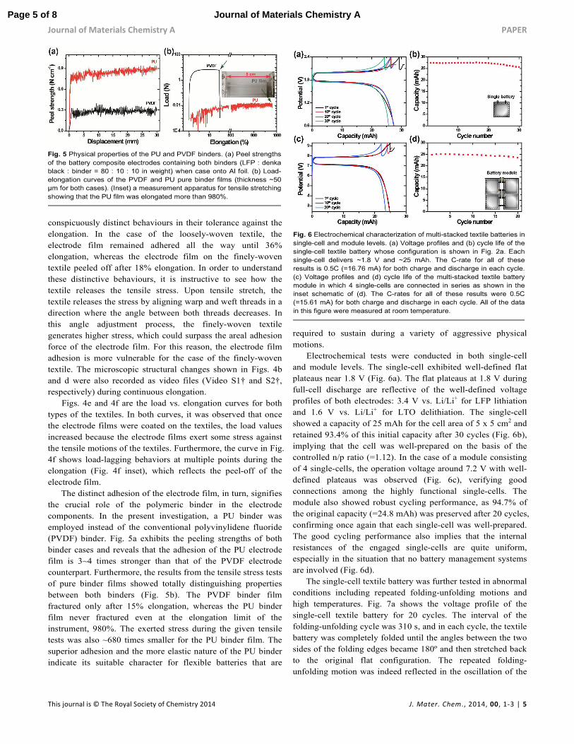
Electrochemical tests were conducted in both single-cell
and module levels. The single-cell exhibited well-defined flat
plateaus near 1.8 V (Fig. 6a). The flat plateaus at 1.8 V during
full-cell discharge are reflective of the well-defined voltage
profiles of both electrodes: 3.4 V vs. Li/Li+ for LFP lithiation
and 1.6 V vs. Li/Li+ for LTO delithiation. The single-cell
showed a capacity of 25 mAh for the cell area of 5 x 5 cm2 and
retained 93.4% of this initial capacity after 30 cycles (Fig. 6b),
implying that the cell was well-prepared on the basis of the
controlled n/p ratio (=1.12). In the case of a module consisting
of 4 single-cells, the operation voltage around 7.2 V with well-
defined plateaus was observed (Fig. 6c), verifying good
connections among the highly functional single-cells. The
module also showed robust cycling performance, as 94.7% of
the original capacity (=24.8 mAh) was preserved after 20 cycles,
confirming once again that each single-cell was well-prepared.
The good cycling performance also implies that the internal
resistances of the engaged single-cells are quite uniform,
especially in the situation that no battery management systems
are involved (Fig. 6d).
The single-cell textile battery was further tested in abnormal
conditions including repeated folding-unfolding motions and
high temperatures. Fig. 7a shows the voltage profile of the
single-cell textile battery for 20 cycles. The interval of the
folding-unfolding cycle was 310 s, and in each cycle, the textile
battery was completely folded until the angles between the two
sides of the folding edges became 180º and then stretched back
to the original flat configuration. The repeated folding-
unfolding motion was indeed reflected in the oscillation of the
Page 5 of 8 Journal of Materials Chemistry A

PAPER Journal of Materials Chemistry A
6 | J. Mater. Chem., 2014, 00, 1-3 This journal is © The Royal Society of Chemistry 2014
voltage profiles with the same intervals. Even under such strong
physical motions, the textile battery preserved 79.5% of the
initial capacity (=24.5 mAh) after 20 cycles corresponding to
1,000 times folding-unfolding repetitions, suggesting that the
cell holds remarkable mechanical stability by utilizing the
internal fiber structure of the textile that releases the substantial
stress efficiently while maintaining the adhesion of the
electrode films (Fig. 7b). It should be noted that the degree of
the folding in the current investigation was exaggerated, and
actual folding/bending required for flexible batteries would be
much more moderate. Also, for the outdoor and building
applications, the textile battery should hold good
electrochemical performance at high temperatures. To test such
possibilities, the single-cells were evaluated at 45 ºC. As
depicted in Fig. 7c, while the voltage profiles at 45 ºC exhibited
almost the same voltages and plateaus as those at room
temperature, the profiles at 45 ºC showed sharper voltage drops
at the end of plateaus, which is attributed to increased ionic
conductivity at the higher temperature33. At this temperature,
the textile battery showed 77.5% retention after 10 cycles (Fig.
7d). The observed capacity drops might originate from
unwanted side reactions with the Ni-coated textile that become
amplified at high temperatures. (See Fig. S2†). This issue could
be resolved by finding proper textiles or performing post-
treatments, but we leave it as a future investigation.
Conclusions
In conclusion, we have demonstrated large area flexible LIBs
with the multi-stack configuration. The mechanical stability of
both single-cell and module levels during aggressive
folding/bending motions originates from the use of the textile
current collectors that release tensile/compressional stress
efficiently through 3D porous structures. Moreover, a vast
number of the possibilities in connecting the single-cells into
modules represent additional opportunities in tuning the
operation voltage and cell capacity. The present investigation
suggests that flexible LIBs could find a broad range of unique
applications beyond IT items once the cells are designed
carefully from each component in a single-cell to module
assembly.
Acknowledgements
We acknowledge the financial support by the National
Research Foundation of Korea (NRF) grant funded by the
Korea government (MEST) (NRF-2010-C1AAA001-0029031).
This work also supported by the Technology Innovation
Program funded by the Ministry of Trade, industry & Energy
(MI, Korea) (MI-2013-10044519).
Notes and references 1. J. M. Tarascon and M. Armand, Nature, 2001, 414, 359-367.
2. Y. Chen, J. Au, P. Kazlas, A. Ritenour, H. Gates and M. McCreary,
Nature, 2003, 423, 136-136.
3. M. Armand and J. M. Tarascon, Nature, 2008, 451, 652-657.
4. J.-S. Kim, K. Kim, W. Cho, W. H. Shin, R. Kanno and J. W. Choi, Nano
Lett., 2012, 12, 6358-6365.
5. Z. L. Wang and W. Wu, Angew. Chem., Int. Ed., 2012, 51, 11700-11721.
6. R. F. Service, Science, 2003, 301, 909-911.
7. B. Scrosati, Nat. Nanotechnol., 2007, 2, 598-599.
8. H. Nishide and K. Oyaizu, Science, 2008, 319, 737-738.
9. S. Xu, Y. Zhang, J. Cho, J. Lee, X. Huang, L. Jia, J. A. Fan, Y. Su, J. Su,
H. Zhang, H. Cheng, B. Lu, C. Yu, C. Chuang, T.-i. Kim, T. Song, K.
Shigeta, S. Kang, C. Dagdeviren, I. Petrov, P. V. Braun, Y. Huang, U.
Paik and J. A. Rogers, Nat. Commun., 2013, 4, 1543.
10. W. Chen, R. B. Rakhi, L. Hu, X. Xie, Y. Cui and H. N. Alshareef, Nano
Lett., 2011, 11, 5165-5172.
11. J. P. Rojas, G. A. Torres Sevilla and M. M. Hussain, Sci. Rep., 2013, 3.
12. G. Zhou, F. Li and H.-M. Cheng, Energy Environ. Sci., 2014, DOI:
10.1039/C3EE43182G.
13. H. Gwon, J. Hong, H. Kim, D.-H. Seo, S. Jeon and K. Kang, Energy
Environ. Sci., 2014, 7, 538-551.
14. Y. H. Kwon, S.-W. Woo, H.-R. Jung, H. K. Yu, K. Kim, B. H. Oh, S.
Ahn, S.-Y. Lee, S.-W. Song, J. Cho, H.-C. Shin and J. Y. Kim, Adv.
Mater., 2012, 24, 5192-5197.
15. S. Leijonmarck, A. Cornell, G. Lindbergh and L. Wagberg, J. Mater.
Chem. A, 2013, 1, 4671-4677.
16. S.-Y. Lee, K.-H. Choi, W.-S. Choi, Y. H. Kwon, H.-R. Jung, H.-C. Shin
and J. Y. Kim, Energy Environ. Sci., 2013, 6, 2414-2423.
Page 6 of 8Journal of Materials Chemistry A

Journal of Materials Chemistry A PAPER
This journal is © The Royal Society of Chemistry 2014 J. Mater. Chem., 2014, 00, 1-3 | 7
17. V. L. Pushparaj, M. M. Shaijumon, A. Kumar, S. Murugesan, L. Ci, R.
Vajtai, R. J. Linhardt, O. Nalamasu and P. M. Ajayan, Proc. Natl. Acad.
Sci. U.S.A., 2007, 104, 13574-13577.
18. L. Hu, J. W. Choi, Y. Yang, S. Jeong, F. La Mantia, L.-F. Cui and Y.
Cui, Proc. Natl. Acad. Sci. U.S.A., 2009.
19. Q. Cheng, Z. Song, T. Ma, B. B. Smith, R. Tang, H. Yu, H. Jiang and C.
K. Chan, Nano Lett., 2013, 13, 4969-4974.
20. L. Hu, M. Pasta, F. L. Mantia, L. Cui, S. Jeong, H. D. Deshazer, J. W.
Choi, S. M. Han and Y. Cui, Nano Lett., 2010, 10, 708-714.
21. L. Hu, F. La Mantia, H. Wu, X. Xie, J. McDonough, M. Pasta and Y.
Cui, Adv. Energy Mater., 2011, 1, 1012-1017.
22. K. Jost, C. R. Perez, J. K. McDonough, V. Presser, M. Heon, G. Dion
and Y. Gogotsi, Energy Environ. Sci., 2011, 4, 5060-5067.
23. K. Wang, P. Zhao, X. Zhou, H. Wu and Z. Wei, J. Mater. Chem., 2011,
21, 16373-16378.
24. K. Fu, O. Yildiz, H. Bhanushali, Y. Wang, K. Stano, L. Xue, X. Zhang
and P. D. Bradford, Adv. Mater., 2013, 25, 5109-5114.
25. Z. Weng, Y. Su, D.-W. Wang, F. Li, J. Du and H.-M. Cheng, Adv.
Energy Mater., 2011, 1, 917-922.
26. Y.-R. Kang, Y.-L. Li, F. Hou, Y.-Y. Wen and D. Su, Nanoscale, 2012, 4,
3248-3253.
27. Y.-H. Lee, J.-S. Kim, J. Noh, I. Lee, H. J. Kim, S. Choi, J. Seo, S. Jeon,
T.-S. Kim, J.-Y. Lee and J. W. Choi, Nano Lett., 2013, 13, 5753-5761.
28. H.-J. Ha, E.-H. Kil, Y. H. Kwon, J. Y. Kim, C. K. Lee and S.-Y. Lee,
Energy Environ. Sci., 2012, 5, 6491-6499.
29. E.-H. Kil, K.-H. Choi, H.-J. Ha, S. Xu, J. A. Rogers, M. R. Kim, Y.-G.
Lee, K. M. Kim, K. Y. Cho and S.-Y. Lee, Adv. Mater., 2013, 25, 1395-
1400.
30. H. Gwon, H.-S. Kim, K. U. Lee, D.-H. Seo, Y. C. Park, Y.-S. Lee, B. T.
Ahn and K. Kang, Energy Environ. Sci., 2011, 4, 1277-1283.
31. N. Li, Z. Chen, W. Ren, F. Li and H.-M. Cheng, Proc. Natl. Acad. Sci.
U.S.A., 2012, 109, 17360-17365.
32. H. Y. Jung, M. B. Karimi, M. G. Hahm, P. M. Ajayan and Y. J. Jung,
Sci. Rep., 2012, 2.
33. F. Croce, G. B. Appetecchi, L. Persi and B. Scrosati, Nature, 1998, 394,
456-458.
Page 7 of 8 Journal of Materials Chemistry A

Graphical Abstract
Large area multi-stacked lithium-ion battery modules are developed for flexible and
rollable applications by employing conductive textiles.
Page 8 of 8Journal of Materials Chemistry A