lANRENCE LIVERMORE IABORAlORY
24
,, This is an informal report intended primarily for internal or limited external distribution. opinioru. and conclusions staled are those of the author and may or may nol be those of the laboratory. UCID- 16719 lANRENCE LIVERMORE IABORAlORY o1 Callomia/Livetmore. Calilomia Rcx:K )I)()£ LING IN 1nSOR74 • A 'JlfO-DIM:NSIONAL LAGRANGIAN SHcx:K PROPAGATHJI C(J)E Donald E. Burtm John F • Sc:hau March 19. 1975 , ...... tar u. s..._ E-. C:C& ___ --- .. ,..fnt-41 i: - -·-··-
Transcript of lANRENCE LIVERMORE IABORAlORY

,,
This is an informal report intended primarily for internal or limited external distribution. Th~ opinioru. and conclusions staled are those of the author and may or may nol be those of the laboratory.
UCID- 16719
lANRENCE LIVERMORE IABORAlORY Lhvers~ty o1 Callomia/Livetmore. Calilomia
Rcx:K )I)()£ LING IN 1nSOR74 • A 'JlfO-DIM:NSIONAL LAGRANGIAN
SHcx:K PROPAGATHJI C(J)E
Donald E. Burtm
John F • Sc:hau
March 19. 1975
,...... tar u. s..._ E-. C:C& ___ ---.. ,..fnt-41
i: - -·-··-

Abstract
Introduction
CGfTE~TS
Solution of the rncrementally Elastic Problem
Pressure Integration
Ductile Shear Failure
Brittle Shea~ Failure
Tensile Failure . ••
Artificial Viscosity, Stability, and Energy
Future Work
References
-ii-
1
1
6
11
14
16
19
21
22

f ROCK ~lODE LING IN 1CNSOR74, A niO-DHIENSIONAL L\GRANGIA.'\ SHOCK PROPAGATION CODE
ABSTRACT
TENSOR74 is a major revision of TENSOR, a computer. code designed to solve stress
wave propagation problems in t"'o dimensions. The major physics modificatims in TENSOR74
are in the area of constitutive model i ng of solid materials. The new models, which are
described in detail, take into account pore collapse, ductile and strain softening
brittle failure, as 1•ell as tensile failure with void opening and closure. In additim,
a modified form of linear artificial viscosity is describeo.
INTRODUCTION
TcNSOR74 is a major modification of the TENSOR code which was originally conceived
and written by Maechen and Sack1 and later adapted by Cheny. 2 TENSOR74 provi des
numerical solutions to problems involving the propagation of stress waves in two
dimens ions. The code is a Lagrangian, explicit finite difference, cmtinuum mechanics
code "hich can take into acco\.Dlt highly nmlinear material behavior.
TI1is report gi ves a brief overview of the continuum mechanics equation~ which are
solved and describes in detail the rock mechanics IIIOdel used in TENSOk74 . The finite
di fference equivalent for the differential continuum mechanics equations has been treated l 7
i n co•:sider ah le detail by others •- and is not discussed here . The rock mechanics mode 1
i s a t~<o-dimensional version of a model fo:nnulated by J. Schatz fOT SOC73, the one
dimensional companion code of TENSOR74 . General di scussion of the philosophy of
consti tuti \·e mode ling used in both TENSOR74 and SOC73 may be fot.md in Ref. 3.
As a convenience to cod~ users , Table 1 list s t he relat ionships between the notation
~~ed he rein and code variables and input }arameters.
SOWTIOO 0 111: INCREfoENTALLY ELASTIC PR(JILUI
Dur ing each code cyc l~ . stress loading is treated initially as an incrementally
elastic or "hypoe l asti c"A process which can be described by two independent elastic
moduli over the range of stresses encount ered during a single time step. The calculated
stresses are later adjusted, i f necessary, to take into account any inelastic behavior
as described by the constituti ve model.
The detai l ed f inite difference solution to the incre.entally elastic problea has
been discussed in considerable detail elsewhere, 1•2 sr only a brief outline of the
-1-

r-· --- -- ---~. ·-=·~---~~" .' --
I N I
Table 1. Relat i onship between notat i on and code variables or .nemunics .
1 LNSOII ~prlal Par-t!rs 1:rld Varl ab les
carer Poaitlm Notation Vari ah l e Notation
I Po u u r 2 ~0 \ ' u: l •v or - ~0 R
• 10 l
s Material n~b•r II\, VN Vo l~ chan1e • ll•
I> c I (j Q
•W or .c4 8 N1111ber of ~A (P) t lib It r I'
9 N....,.r of ' • (I' ) taiJir vz Initi a l voh• • l/'R
10 Nu.ber of,., table 'r.(P) AM Man • l /•
II AI susr c
12 Az AN Zone af't':a •
ll As 1 U.Q ttl. 1111ht lna tl• • blu
14 ~:, Til s r IS - TZ \ 16 - TRZ S • T
rt r t 17 'l QR Qr 18 'I QZ Q: 19 'z QIIZ (jrl
20 cl SSL overt.ur.Jen pr~uure • bi to
21 '•o SVI
22 - 1;0N~ 'v 23 N....,.r o f lv(P) table IJVf ln l t1 ul c~reralt~~•
24 '• ... ~ '· 2S NUIIber lf( P) t 111> le "' 1\ r • r • r 0 26 c l Zit AI • I lu 27
21 overtturokn cu•ut•t
2t OVertturd4ttl conat•t
JO
AclcUUona l lENPLT ,.,_lcs
11t1e11011l c Notation
Rf 'o u I
MilO ~ RJIOA Tan ' 1t& / r )
sr ;;;r.-;;1 SPA
r . J 1 T• (u
1tu,l
CUll LV .... !!. II IV\' V·!;!.
l'liiiUJ V• A!. 1211 1l l1 Ill I I ll! y y
I' I All r H:J ( .. \
'"" I)
CIM' t • I MA1 Mat.rlal nllllller
LOS Material atatt
111M 1 r
TU ,, TPP Tt TP "t Sill I 1 I
~ ·Gl T2 SIGl Tj
s t roA .. P•Q P•Q
l£11 Klnt II c enu ty "-totlty
11.0 ln ttot~al ene ,..y <len• lt r
T£11 To tal enerar oknal t y
UN Spec ifi c Unet ic nuar
l EN Spec ifi c IIIU m a l enUIY
11;111 Spec if l ~ t otl l ennay
Addi tiona I TENSOR Outout N-s
lleaclina
NJ..-'AX
ANG
Tl
T2
Tl
llEI. R
t.ELZ
QY
~m ljl ,, T2
Tl
Notation
Ar • r • r 11 ~z • r • 1
0 I qulva len\ of Y for Q ttnaor

solution will be presented. Althouah TENSOR74 can be used in e ither plane or cy lindri ca l
coordinates (r, z , cp), ~.lle latte r mode is most often used and, consequent ly, will be the
one described here. The region to be described in the calculation is discretized int o
a lar,e nuab~r o! quadrilateral zones in the r-z plane, the z-axis be ing the sr-metry
axis . The state of the material wi thin each zone is described by 3 stress tensor (T) and ,. a strain tensor (~} which are both separated into their isotropic (P and 9} and deviatoric
(~ e~d t> caaponents:
• -PI + .
(1)
:.] "here ! is the identity tensor. The pressure or •• stress P and the volumetric strain
€ are then &i ven by
(2)
The int r oduction of the first invari ant quantities, p and e, allows the ' components to
be carri ed iqJlici t ly in the solut i on. The off-dia&O" :.l .:011f!onents, T rz and Sr:, are of
course identica1, as are £rz .nd er:·
The calculational procedure followed in a aiven zone durin& each cycle is shown in
Fia. 1. In t entS of P and the deviatori c stresses, the conservation la"'s reduce to the
coupled ~quati ons of QOtion,
,.·, • - .!_t p S ) + ~ S • rl (2Sr • Sz} + P"r ~r - ar' - r ~% rz •
(3)
"'here u is the veloci ty , c is the density, and a is the ,ravitational body acceleration.
The di ssipative viscosity teras whi ch are added to each of the stresses to smooth the
sharp discontinuities characteri s tic of shod phen~na are not shown in the above
equations. It is the user's option to include the aravitational tenas. When they are
included, each zone is aiven .n initial pressure in an effort to partially balance the
, I
-3-

/ ln.lostic
con1t itutive .,.,., I
Generalized Hoole• ' t low
\ Strain rates . . . . e e •• r z rz
~ p s ~ s
r z rz
Fi&. l. Cal culatiCIIal cyd~.
-4-
Equotton of motion
Accele'9t iotn . .
\ lnt..,:oiom
I Velocities
/ Integration
" 'J , z

equations of motion to produce~ initial e~uili~riu.. -nile thi~ rr~cedure is in cOBplete
be c ause the <Wviators art' not also in i tiali:ed, it is prob~ly adequate for r::any prob lems .
lhe acce lerations an then integrated to yield the velocit ies, ur md u:' an c.J t he
new coordinates, r and : . From aea.rtrical considerations, the strain rates c an then be
calculated as
u r . -r
er • !.1:.~ u - .:,_ u - ur) 3~or r o: : r
l rz (4}
rhe ~sulti~' strai~ rates are then used to calculate the elastic stress rates using
_. generali:ation of Hooke's law that assumt's the aaterial is describable by an elastic
bu'.IJ. modulus k md an elas it: shear modulus u which are c:aaracteristic of the cu.,.rent
s tate of the material. Thi s i! a "variable 1110dulus'' m~el in that it &S!H.II."lt' S a pressure
J ... r~·nJent J.. .nd a silili lar dependence in 1- if a constmt Poisson's ratio (v ) is assigned.
Th is .!TJ'>U through the J"t'lationship from linear elasticity,
In add!tlon, the bu ll.. modulus ma) also ~nd on the prt'vious state of the material, as
J 1 scu,.,.~·d be low. The i sot ropi c and Jev i atori c stress rates are then given by ,
s = 2u•\ . zs 1.. r r r: r:
5 Zue. 2S 1.. r: r :
= :!I-~ . (S - 5 r)"'rz . r: r : : (5 )
a.hert' the f ac t Qr
-5-
is an angular vcloci t~· which corre cts for t he ri gid rody moti on of the tone during t he
t ime step. The f i n i t e diffe rence equa t i ons actual ly used i n t he code carry an addi t ional
h1gher order rotati on te rm not sho,,·n i n t he above .li f fe rentia l equations . 5
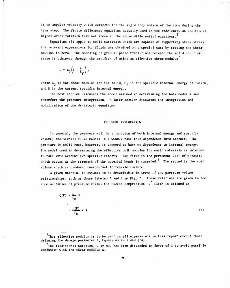
Equations (5) apply t o solid nate ria ls wh i ch are capable of suppor t ing s hear s tress .
The relevant expres sions f or flu1ds are obtained 11• a speci :~ l ca~ by sett i ng the s hear
modu lus to zero. The modeling of gradual pha ~e transi tions bet-.een t he solid and flu i d • s t ate is achieved through t he art ifi ce of using an effecti ve s he ar modulus
-.·here IJO is the sheax modul ill- f or t he solid, E; is t e spec\fi c in t ernal energy of fusion,
and E is the current specific internal energy.
The next sec ion discusses the model assumed in determin int the buH. mod" lus and
therefore the pressure integrati on. A l ater s e ct ion d i scusses the integration and
modifi cat ion of ·t he de"iatoric equations.
PRl:SSURE 11'\TEGRATl Cl\
In general, th~ pres~ure will be a fun ction of both internal enerJY ami specific
volume ; and severa l f l ui.l models in n:ssOR7~ take thi s dependt:nce into accou:t. The
p re~sure i n solid rock, however, i s assumeJ to have no penJence on internal energy.
The model used in de termin ing t he effective bulk l!lodulus for earth miiteria l s is i ntended
t c. tale i nto acco~t t lo'o specifi c effects. Tlw f' r s t is t he permanent los ~ cf p or osi t y
~<'h ich occurs as t he strength of the material bonds i s .. xceeded.6
The seconJ i s t he \ 'oid
volume ~o·hich is produced concomi tant to tens ile failure .
A a iven matt-ri a l i s as sumed t o he describable in terms ~ f WO pressure-volt..
relationships, such as those lal>e led A and B ir. Fig. Z. These relations are glVen t o t he
code as tab les of p ressure vcrsu~ the , xce~s coqJressi on ~o: . i ch 15 defined as
•
~(P) a £_ 0 "o
( b )
This effective modu lus is t o be u~"i i n all express ions i n t his r eport except those defining the damaae parameter £ , Equat1ons (20) and (24) . ...
The tradit i onal notation , lJ or mu, has been di!' carded in favor of t; to avoid pos~i l>le
confusion with the shear modulus IJ.
-6-

.. :; .. .. !! ~
Excess c.ompreuion ( { = ;J/ p0 - I)
Fig. 2 . Pressure -volume model.
-7-

~o ' ere r0
1s t he s pecific vol~ at I' In the se tenns , the buH.. modulus is given by
0 Q • (7)
~o. n.-~ ::& i s t he slope of t he cur-N>nt t rajectorv i n P- L; spa~ .
he prescrip~ion fo llowed im determinm~ a , and then- f ore 1.., 1s il lustrated in Fi a . ~
The Clat t'nal is tal..en to load alan& a path temed t he virain loadin& path (A) . The
subsequent un loadina l>ehavi or ~nds em t.he r .axi:nm coq~re-ssion .:;c e xperi en.:ed t-· t he
t;;ttenal nola~n-e to t "'o e.xperioental points .;1
and .:;1
• If t;J:l has not e:lceedc-d .:;1
• then
no ~=anent CoqJactirn can tal.e place bec&USe the inter .. al nnosses have not ex~ded . the parr "~ll s trength ano.l allu..e pr.~re collapst- t o occur . I f the rAXiJ:IUI:l ocpression
'::. has exc:rede ; _.then aJ l port-s havt- p resw:1al>ly collapsed; and tlv aat~ria 1 JalSt
unload alana t e pathS for co!l!plet.elr crusht-c! n.1tt- ria!. !n principle, tht- c:n..sht-d pat ':!
~o ould be tht- loachna and unload.ie<> path f or ? U:rt' nonpor ous r-atri:l Cl&tt-rial. The
Hl tercept ':) lS tilt" lll&lllJ:U:I peraant-nt Coql&ct i an and lS .approxi~:~ately equal t o t he J&S
f lllt'J poros t y of the .~:~aterial.
:.'hen 'll. t s ~;reatt'r thllll ' 1 t J oes nat ~~t excet"d .:; ~ , t hen t ht- ~ateri a l is only
parti all y c~act t'd and c:ust ~mlolld alm' a path bet· t-en t he ~he..! and \'i rg in loadina
curves . I f t he part1al pore coll apse o;eno ~-:'l:lant'n t, the approrriate un loadinr path
~o. ould havt- to~ cons istent ~oi th the un loadin& beha\·ior of t he fu l ly crushed matrix
11\aterial. That 1s t o s:~y , partially crushed mater1al ~o.ould .'la\'t- to unload along path
C i n Fia. 1, ~o.h i ch 1s paralle l t o t he crusht-d path B .nd ~>lll i ntersect the I; axis at .. -. T '
l!o~oeve r, partl a llr ccx:pacted t ~r ... l usually e >Jtibi ts t' last 1 reco\~ry of S Ollie
p orosi t y , prt's ucat-ly because m-any of t he pol"t' ~oa l !< ha\'e not !>t-~n stress~d to fai Jure.
Thi!' J:Jt>31::' that the materia l cust unl oad alan& Sa"X pat t. IJ ~o.h ich !ies t o the left of C .
The s~c1 ficatim of this path is ac <.. lishe as foB ·s. Tne nos idua l poros ity, " hich
is the i ntt-rcept :; r of fl ~oith tht- :; axis, can t-t' deduct>d frOI:l l al>.:>ratory data and
t-xpres s ed a s a polrnc:aiai ,
.
(8)
In practice, tht- slope of curve A bet"t"t"D the 0r111n and ~; 1 i s usually selected t o yield the correct sonic ve lC'ci ty for l<N amplitude s:Fai s.
-8-

. /
"'hen t.he sue of the \ coefficient.s must. t>e un i t y to i uarantee that ~ r l .;:? ) = r;3
. "'"he
quan t lty x is relatec! t o t.he maxiiiU!l coq>ression and is expres!'e c.l as a fr:~ct ion
em - 1;1
.. 2 - 1;1 < 1 • (9)
It 1s t.hen necessary to nquire that. I1 lie to t he l eft of C and inteTSect the '· au s at
'r' If the ncoven d porosity ( I; • - r; ) is ass umed to be restond as a linear fun ction r • r of P, then t.he folltl'>ing n lation~hip for o along path D 1S easily derivab le,
1 1 mJ" a.m·
(.
. .
.. r - .; p m
r (10 )
~here oc is the slope of C at pressun P, ~~d Pc is the ~r~ssure corresp ondin& to the
m&Jlillll.ll:l coapnssion :;1:1 . Since :1 i!O determined , the effective bulk It<. u l us J.: is knO'-Tl
and the p ressun integration can be accc:q> lished.
The precedin& discussi on coocemed a IIIOde l for the behavior of microscopic.: voids
normally contained "'ith).n rod or soil materials. A se1..ond t }7 e of void mus t also be
t~en into accOUJlt in t he pressure calculat1on . These are voids formed by t e open ing
c.>f crad s in the rod. durin& tensile fai l ure. TENSOR74 J oes not J i terally creatf' craded
~one s, but 1t simulates the effect of cracls in a continuum . The occurrence of tensi le
f~lure dur1n1 unloadin& causes the material to follow a path to the left of the normal
un l oad1nJ path. This hebavi_:- is mo6eled in TEKSOR74 by adding a pressure correction
~Pt to the pnssure "'hen tensile n l axation is occurrin&. This can happen during both
lo .. din& m:i :.mloading. Sunlar ly. ~hen voids c lose, a correction 6Pc is subtracted. The
P t calculaTJ on '"l II t e descr ibed in detail •-her. :ensile failure is c.li scussed. For n""· ,
lt • tll be s.Jf!I: t nt t say th.n l.Pt i s indicati\·.: of the void volUDe product•d by tensile
fail ure. The votds .. re :al en to incn ase at a rate determined by the bulk modulus k o r
e ui\'a lenu:. the slope :. , so that the t ota l "'oid volw:~e i s given by
2 : P - :r
t c :.(r)
(II)
t
In pract i;:e, o 1s assumed to be approximately constant during tensile failure so that
this pa rt icular sumnat 1on is simp li fied t o
• Infinite or negative s lopes are not forbidden by Eq. (10). Should such a value be calculated, i t is replaced by the slope of a straight line dra .. n bet~een l;m and z;r. Although setting the slope to 0c might seem to be more appropriate, such a pr~cedure could cause unintentional hulling by unloading to the left of the origin, depending on the shape of path B.
-9-

p \'
(: r - .: r ) t c
ami a "void pressure " Pv 1s accn-:ulatetl ins tead of~\ . \"aid openings from tensile
failure add to t his sumcati cr.; void closure~ subtract.
The ne t change in pressure :luring one eye 1<' t hen consists of three separate
cont r i lout icns
(12)
~ohere 6.:; = p0G t / p0 is the incremen tal voluml· change. The first term is the simple
incremental ly elasti c contri bution . The second tern contributes only during tensile
failure, and the t!tirtl term contri butes only dunng 1 adin g or reloading provided there
are vol ds.
TI1e fo rm of 6Pc during loading mu s t be such r ha t ·pis small "·hen Pv or .:;v is large,
alla..-ing the voids to close "·ithout resistance. In fact , if the ·mau:rial i s not a llo~;ed
to bull., cP must be :ero until the voids are closec.i.
bu l l.ing is
A form for (p ~;hid-. does allow c
t P c {' 0
l oading (cP > 0)
tmloading (6P < 0 ) ,
"here r.8
enters a s a .:haracteristic value f ()r the expansion. This fa~ yie l tls the
foll~ing limits f or 6P during loading if th~ 6Pt contribution is i~1oreci,
{.-'/:. p ~"'
\"
6P c.d.:; r Ct~ B \"
L c.d.:; p ~ 0 • \"
(13 )
so that the effect of !;B becomes s i gni fi cant ~;hen P /" is of the orde r of ~ E .:md the
correct extreme limits are obtained . The quauti ty ~ B is an input parame e r to the code
and is reset to 6~ if it falls bel~· this valae. This artifice allows the void c losure
to be spread over a nininum of about five time steps in the interes! of e l · i nating
numerical noise.
As final camtents on the pressure calculati<>n, it shuuld first be noted that nu
rate-dependent effects are incorporated in · ~e pre!'ent pressure inteSlration Secondly,
as di s cussed in the next section, no dilatancy is conside:red in the p .-esent model of
s hear failure. Should di latancy be considered at a later date, it conld be treated i n
-10-

somewhat the same fashion as the void volUI:Ie. Thi rdlf , the t:ec:h&ique .toY ti.nK for
voids is not unique. ~laen chen and Sad.1
in their originlll ~Dian of t.he Tel.~ q
acco~ted for !;v directly instead of P\. · Finan,_-, the Vl:lid c.losa:re i.s il!~t. of L"e
orientation of t he tensile failure ~o.hich produced the Vl:lids. Tl:.e :idleme oE taenc:h9
and Sack also took this orientation into account . In fut~ m.ode-ls, their p:roadl or ~
generalization of it is preferable.
OUCTl 1£ SHEAR FAI WR.E
The ductile ~hear failure used i n Th'iSIJR74 is e~seJ:tially an e:.astic~~aly
plastic oode l in lo.'hich the deviatoric state of the material is cOil.SO"ain~ uot -c.o exc..-ed
som~ failure surface. In general, this sur-fa.c:e would be a func::.i CII. o£ sn-ess t ensor . . 7 d h l)lVanants correspon ing to t e asslll!lption that the oat.erial is initially i.so~:rapic:.
In terns of :he s tress deviators, three such im:a:r.:.mts are
p = -1/3 - J<r • T • r,> 3 r z
11/2 (s; + s 2 + s s + s!)I/ 2 ~D z 1 :
11/3 30 ~sr + s > (s
2 -z rz srsJ]l / 3 (14)
l •at a f or rock materials indicates that the ductile failure surface em. often be adequare ly
o.l<'scribt>d in terms of P and I alone or equivalently P and Y which is de'fined Ul be
y ( ~ I )112 \4 2ll
= 0.8t>6 I
Y is proportional to the octahedral shear s~ress and is equal LO ~ maxinm s!len •
stress (a1
- a~) /~ if c~ equals a 3 as would occur unde~ uni~al loadi ng.
(1.51
However, in the realm of brittle failure (whi ctt occurs a~ laliM!I p:ressure:s t:h:.all
uucti le failure), compression, extensioo, and tor.:.-ioo data o£o5L ~ be rec:cn.cile'li . f .1... • - 3,8 =-- -'-·-into a sing·e failure surface by emplo)flng ool~· tlOO' o .. ue DJ: a:o:an:~. ........eve:rT u=
data can often be reduced to a single surf'ace de'fin:ed in t:oe'DDS of Y omd the quauticy.
(I 3D)l/3
p - 16 • (10}
• llere. we fol1010 the usual conventioo in diescribiq, tlie pri:n.dp:al ~: tll:n a > o in ccapression, and tha-r. 3 ~ a2 ~ cr 1-
-11-

~o;hicb ~ ~o ii = r • r t~ c L;; 1 • :~) /: 1ro-hen c z ~o c~. In the ductile region. ~he
seccr.d um h nqhbib le. ,., thar botJa briu:e 4111d ttlli> fulu.re surfaces will be
de ~ Ill ::e :aQ, o.~ IJII ly Y .i fi z in :.au l.D r i . 3. The sh~ af the failure
Sl:r£ s •s sunlar ~ tha of a :-..n.cl.eT yield =terion.9 The det;ai ls
b l -- space. mnena "iucb
1 - ; _ • ~spall~J ~0 llll:UO:i&l ~ l
:re lcadUt alone otile.r p acw The w ~ ~ oha\'e
tne n~ sea:i_ao.
~ a paLh of slope ~proximate ly
l · 1 or subsequen~
in dle du.cti le
fa:Uu.re: <md the st:re:ss na-:e is
Gil ttie f1i lure sur.faa!' .un: ~ ~ subsi de.
e Cua; tlJe un::ep:ati.aa af t • .e m~:tall~· el.as~1c prd>lem [Eq. (5)]
e sulm::i11Ds sr' s: ..... fai.~ cu::iace 1: £
no m t::llllelC Clll P a~d
- i 'S . "' s. -
l. :t y
S \oh.idl Ul tlU:l a a.lue 7 ll'bicll U6 i1bcm! tlle r: :P. The fi:n~ .:ta
The abcr.e S4::'e5S .adjust:::DeD-x~ c:aused by bila:re. is men c:e:rt.....:i.nly ao:a~~p.mj.ed by
d.aul .. - to t..'l.e mareri aL meas:me ai t.be dzlage is a quantity TenDed the ine lasu c . ·au~ u
1 -= s: I I - I I
~ ~ 11 -~ {16a)
The ab:solllte value is "tAJken be~ the in~egral af this quanticy is iD.tellded ~o be a
me:asw:e of t:he ~Tllde of in.cobe-reltt sua:in uperien.ced by t.be material.
The abQ1::e fOT!!IU Ltti on for ducti le failure dces not. appear explici t ly i;a TE...-SOR74 .
Ratile:r, the duc:ri.le p:r:cb le1D is .foDu ltted as a spo!"cial case of britt l e failure and
so:ess rel:Ixa:: i an u di.~ be lao•.
~ equiva.len.t p-aramet.er di..ffeti:n& fra:l this by about !s.. could have been defined in u~ of Y inste.<id o£ I.
-12-
·.
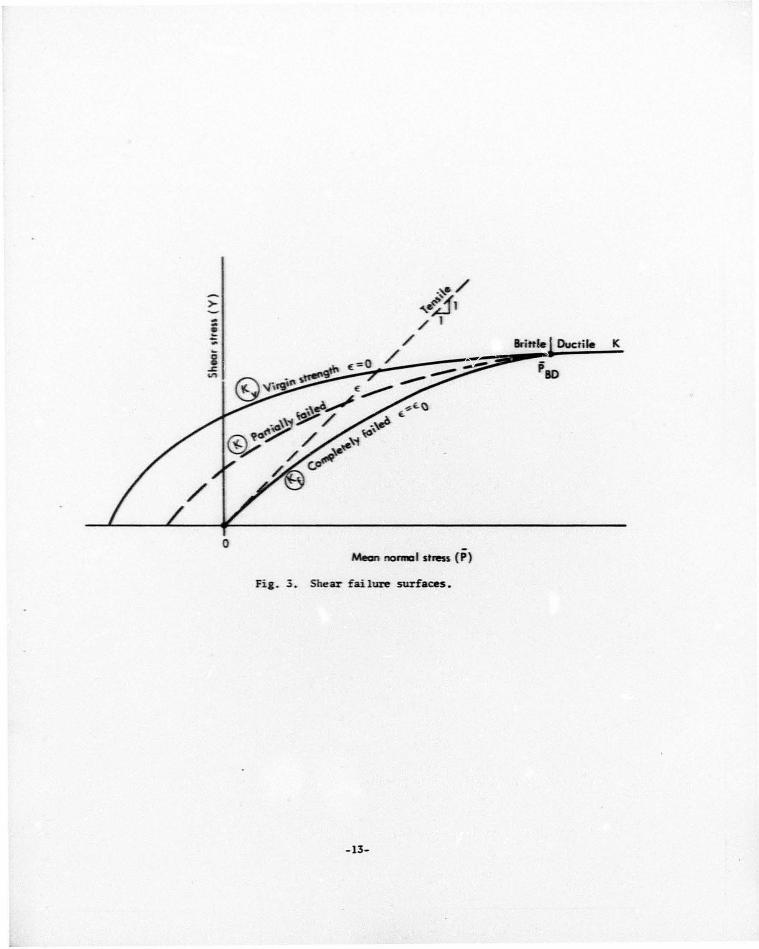
K
0 Mean no-1 -... _ stress (P)
Fia. 3. Shear fail ure surfaces.
-13-

BR ITTLE SI:EA!< f..\ I LURE
The concept of hrit ~ h· f :. llur e employed in TEXSOR~4 is depicted .1n Fig. 3 and assune s
that the st:rength of virgin ( unfai l ed) l1ateri a! can be ch:t racteri:ed by a curve K in v
Y-P space 1\hich can be defined b~· laboratory data, usually triaxial. The unconfined
COI:lpress ion test, for example, will define one point alont a 45° line f1·om the origin.
lf the material has tensile strenj;th , K'" 1.-ill intersect t hl' P axis at a negative 1·aJue
of P. The description of each strer.gth carve i s equ1vai en t to a ~lohr failure criterion,
provided the sl<'pe is less t han unity.
Further, ma!eri al that: l1as fai le:l in the brittle mode is assur.1ed to strain s often
and to be characterized by a l o"·er s trength enYe lope K that depends on the amoi.Dlt of
damage the material has undergone. The damage £ i s defined in some fashion analogous to
£p. In particular, it i ~ assumed that f or sollll' limiting v;; l ue £l1 of the damage parameter
the caterial has coa.,letcly fai led. It "·ill then possess its lol\es t possib le strength
Kf 1\hich arises only from the interlod.ing of the fra~~tents under pressure. Such a
r.1aterial would possess no tensile strength, and Kf should pass through the oritin.
A final constrai nt on Kv• K, and Kf is t hat they just j oin at the transition (P8
D)
into the ductile region, in effect requiring that there by no sharp discontinuit~· in
the strength descriptions berween the brittle and ductill' regions. Figure 3 depicts
curves satisfy ing these constraints.
In terms of K1. and Kf' the location of the effective fai lure surface at a given P
is taken to be
K(£} = {
K - (K - K ) ~ v v f £0
K f
£ < "o (17)
where all quantities are to be evaluated at fl. This form assUIIll'S that the effective
failure surface i s a 1 inear function of £ . Other forms "·hi ch all010 a more gradual onset
or termination could certainly be justifi ed.
It is next necessary to descri be how the Je1·iatoric st resses are to be relaxed in
relation to the effective failure surface K. Onl' opti on 1\ould be to simply "pin" the
material to K as in the case of ductile failure . lil' , f1,,\<.·ever, use a vis(.oelastic model,
which allows s ome rate dependenci! to be taken into accoi.Dlt. The lllodel used for brittle
failure is that of u s imple MaXI\e 11 solid in shear. This in effect llll'ans that s tress
adjustJ:Jent behaves as a vi s cous tern1 in the st rcss rate Eqs. (5). The fonn us ed i n the
code is
- 14-

si [1 _ ~t (1 _ ~)] y > K
s . '" (i • r. z. rz) • (18) 1
-S. y < K 1
~here ot is the time step. This mode l produces a damping which increases as y exceeds
K. and which is zero when Y and K coincide. The quantity T. called the ~laxwell relaxation
time . is the characteristic time over which the stress relaxation is to tale place.
It should be noted that if T is taken to be 6t. then this equation reduces to the
relaxation equa~ion for ductile failure. Accordingly. it is possible to develop an
artifice which allows the unified treatment of both brittle and ductile relaxation. This
i s accomplished by defining.
{
T0 (1 - (Kf/Kv)]
T = 6t as a lower bound
(19)
~here 'o is the input relaxation time. This relation produces an effective relaxation
time ~<"hil.h reduces to 6t in the ductile region. ~hich i s T0 when .:f = o. and which
possesses a smooth transition between the two limits.
The net effect of the above formulation fEq. (19)] i ~< to allow Y to overshoot the
failure surface K in the bri ttlt- re~ion under rapid loading conditions (thus producing
a ··rate ha rdening" ") . and to gradually for c.e the overshoot to vanish as the ductile
trans i t ion is approached. This i s done in the interests of using an elastic-perf~· ·: t l~·
p l astic mu..lel of du.:ti le flow. It m;~y \>l'll he- that rate dependence in the ductile rr-tion
is also desirable. in ..-hi .:ll ca~e l:q. (19) should be IBO<lified or discarded.
lie need finally to fully specify the calculati on of the failure associated strain
E: fo1 11 shear failure.
OE: 2\! l I I
.. ~ 111 .::Lo t Kl - ":" . y
(10)
..-hich is cons i stent ""i th oc p as defint"d for th~ ductile region (E'l . ( lt>;a}) "hen : c t.
The !<hear failure mode 1 as described abo\"e does not tal.e into account she;•T·\·<· 1~
interact i ons ldi latancy and shear enhanced CC~~~paction). This ..-ould nqui re a fl o" rule
that adju!'ts P as ..-ell as Y. Once such a flow rule is adequatt"l)· .tefined. it c:.n be
incorporated in the code in 111uch the same 11*\ner as is the 6P t adjust•nt ducribed
below. The current model also nea:~cts duc tile strain h;ardeninc in which t he- 5trentth
increases with the :!'train. -IS-

TEN S I lL F,\ 1 W R£
Tensile relaxation is described in the princ ipal stress coor•linate system (in which
the off-diagonal CoqJonent T 12 vani shes). Th i s system is obtained by a rotation in the
r-z plane of
~ =rtan-1 (s~~zsr) •
"'hich results in principal stresses of
~ res - s )~ • czs Jz]II2} L: r z rz
(21)
If any of these are positive, the material is in tension. r3
is al~ays in the ~ direction
and is cOIIIIIOilly referred to as the hoop tres~. As r1
> r2
by definition, r2
is the
most compressive of the two and is direc~ed perpendicular to the shock front. T1
is the
maxim\.1!1 principoll stress in the r-: plane but may be less than T 3
and, by default, lies
parallel to the shod. front in compressive shock loading. The tensile states typical!:.
encountered are those in ~hich t~o of the principal stresses are tensi le and the third
is c0111pressi ve. In '\' -P space, these states 1 ie t o t ho.> left oJf the dashed line of unity
slope depicted in Fig. 3.
In the code, the criterion for initiiiti on o f ter. :< i l e iai!ure is tal-en to llt' t.he s:~r.~e
as that fo r shear failure, although the re la.xat i on technique is ..lifferent. This
un ified shear-tens ile rai lure criterion c rres pooJs t t he notion t l:at ten~i le fai lur('
oust be pre.:eded hy the creation of .:rad!' I·~· large stress deviators. ~C<' a crad has
occurred f o r any ro.>ason, it is then free t op<'ll 1i t here ; s tt-nsi , 'll . .r\lon~ "ith the
openinr. o f the cracl., tensile stre!'!' J"<" luatJon o.: .:ur~ . • \ 1 1 p:- inc: pal :' tresses ~hich
are tensile a re alla..ed to relu. Unlil.e ::ch<• a r fai lure, 1n "h1 .::1 ~ he :-.atC'ri3 1 s trength
i s gradua lly reduced t o :ero, the l:lateru ll.-ha,·e :o: unJC'r tC'n si l(' fai lure as ii its
tC'ns i le s trengt h has I•C'tm inst lUI taneous ly sC't t o =•· r "hen ~;, .. fai 'Jun· surf act" i s f i rst
reached . .r\ltC'mativcos to this ;approach aJT J i scus s.-.! l ate:- .
The JT!;u;at i on DO.Wl for tensi l e f:lilure as :&jlai r. : alen t o I'<' a ~lil~~C'l ~ l id, so
that the- temsi le princiral stre~ses aJT ad _i us teJ as !c> l l t'" S:
. The .:C.'f\\'entiOll f~> Jl t ... C' J in o.IC'fin&n, : IS llt•t &..!eli~ .·a: t tl,;at C'f ,! , i :l'rC', 1 . 1 1 1:
te:~si otl . an.! T 1
..:. T:, and 13
lies an the' ; .llrC' c t&<.el.
-It>-

T. > 0 l
T . < 0 1
( i • l, ;: • 3) (22)
in which the ti Ide indicates the old value froa Eq. (21). Us\.lally 1 is wry close to ,0
[Eq. (19)] because most tension occurs ncar~= 0 at which lf • o. The relaxation ti~
for tension :md shear have been taen to be the same for lad of COJitlelling reasons why
they should not be.
It is next necessary t o find the ne10 values of S , S , and S corresponding to the r z rz
tensile-relaxed principal ~tresses. If it is a$su.ed that the opening of tensile cracks
as modeled by the above relaxatim does not rotate the p£•incipal coordinate system, thea
th~ transformatim Eqs. (~1) can be inverted to yield,
cos ;:~
During the relaxatim, the trace of the !tress tensor is altered, ,io that the .
pt·essure and other invariants must also be adjusted. The expression for the pressure
correct • on is
6Pt"' P - P
6T. l
(23)
~o·hert' 61 i i!' the ~ >Wit by 10hich each of the tensions was adjusted. This is the final
..:orrt' ction to the pr cssun.• .:alculatim.
Because tensile iai Iurc also alters the second deviatoric invariant, the final
stt'p m tht' tcnsi l•· failure scheme is to increment the acc\lllulated damage. In addition,
~oe a.ic.l a tl•rn ~ohich represents the volumetric strain associated with crack opening.
r-;u~.
6.: • ; .. It I I • t I6P t I •
~o·h·· re each tenn is Jt'tcrmined by comparing the old and new values for I or P t,
re "P'' ;t i \.t' ly.
(24)
Tht• foregoing has l•een a dt'scription of the priaary tensile failure model used in
rt:SSlll:- 7-1. ·the moJel i!' intended to be a isotropic continuum model and consequently
2escnbes incoherent breal.age. That is, the planes of separation or fracture are assumed
~ " be r:md~l~· <Jrit•nted. Such a model is easily defensible in a one-dimensional code.
-17-

110\.ever, the de s irahi li t y of :m i sotrop1 .: 1:1odel iu a t~ooo- Jicrn ~iona l coJc i s , 1 ucst iouabl~ because ten s ile f :tilure !<hould incl uJc anisl>t ropy \l .l aiq;n.·d .:racks. lor e :>.a1:1p :c ,
s uppose T3 > T 1, and that T3 is pri nan ly respoosil ie fo r J riving the materi a> t o f a i l ur~ .
Intuiti vely, one 1\"0uld expect t ha t tht' fr-:tct ure plane ~ooould · e perpendicu lar to 1 _. A .)
description of this phenanenoo ~oo ould n•quire t hat T3
be aJlC'\;e d t o re lax , and tha t tht'
material r.1aintain it s strength in the T1
direction. Ule ~ooa: t o a chieve such . .r. e:· l·e c t
I.'OUJd be to test each tensile principle s t rc ~s independ<-nt l: a~a1n~ t a s iug lc en s ile
st rength I i mi t. Only those tensi ons e xcct•di nJ! t !.e lini t 1-. ouJ J t h n ~ rel :!:>.ec. Once
tensi le failure occurs in a gi ven di re .:t i on , t he s t rengt h ir. t ' ·~: dire.:t i a 1 i s al ! <'d
t o drop to zero either gradua lly or illl!ledi ate ly . Su.:h a node ! was eq~loyed r~ · :aenchen
and Sad. 1 in their original ve rsion of t !:e TEI\SOR code .
An alternative method "'hi ch preserv<- ;; the uni fie <! sh.:ar-tensi le hi lure criterion * ~o·as fonnulated in a special version of TLXSOR74. In thi s model, t ...-o t e n!'ile relaxation
schemes "'ere emp Joyed .
T. i\ ( 1 ~t) (rap1d relaxation) , 1 or
ri (1 ~~) T. (slow relaxation) (.5) 1 T e:o
The second equation ha!' an effective relaxation t ime of TEl/ £ ~o·hich is l arb<' wtil the
material is heavily damaged . "'" in the previ ous model , t he r.1axi r.n.u:·. principa l stress ~oohich
is responsible for failure (say, T3
) would be all""·ed to relax rapidly according t o the
first relation. T1 '-'OU!d follo"' the second relation in l:q. (25 ) and '-'OU lci relax s l o~oly
or rapidly according to the extent to l<'hich the material i s d amaged. Because of the
rapid relaxation of t3
relative to T1
it may ,,ell l e t!:;; t a fte r a fel.' cycles their roles
are reve rsed (T 1
> T 3). Thi s situation is h:md! cd in t h<' follohin~: manner: If Y
exceeds the effective failure surface 1\ at :my given tir.lC, the r.ost t<'nsile !'tress a t
that time is flagged and assilllled the rapid n 'laxatioo in additi on to an y other !'tresses
~o·hich may have been previously flagged. In thi!' ~<ay, both T 3 and T 1 can be relaxed
quickly if e ach ~.'as at one time or anotlwr the tensi 1<' stress ~o· hidl d r o·, e the mat e r i a l
above the failure surface. This scheme taJ..es .: ohe rl:'nt f ailure int 1.' account but a lh''-'S
t he possibi li t r of incoherent relaxation at I arce u;.unage !eve ls .
!loth this scheme and the one of ~laenchl'll :md Sad .. suf fer a seri ous fla~<'. The true
planes o f failure should be fixe d in the rnateri :11 .:o,,r Jinates. In both o f t h<.>se schemes ,
the planes are fixed i nstead in the principal .:oordinate ~ystem 1ohich is free t o r otate
with r espect t o the material as the applied ~tresses vary hith time . This probler i s
especially acute "'hen several energy ,oourn•s .t rt• in\'o l\'(•d or ~oo·h<'n rc f !•·.-t in{; !'Urfaces
are present.
*The version TE~31B haf bffn us ed cxten,oi\·ely in:: stuJ~· of the l1 l a.o;t inj: r ffects long cylindrical charges. 0 •
-I S-
f

Another serious fla., in the tensile failure models discussed above i s that, unlil-e
the shear failure model, the material tens ile strength i s immediately set to zero or1
taJ lure. Because of this discontinuous a lternation in behavior, the first zone i n a
region to fai 1 may be relaxed before adjacent zones are stressed to failure. This
apparently Jeo~<j.s to the prapaaation of finger-like regions of fpilure whi'ch resemble
fr:: c t ure planes. 10
• 11 While there is saDe physical rea lit:• to these prapqating
di s turbances, it would be i11J•rudent to place nuch credencx· in them 1o'iti1out more study.
Fo r the present, it would perhaps be more desirable to f .,uow the shear failure procedure
and let t! lt' t~n,;i le strength be gradually reduced to zero dependina on the damage
parameter. A mode 1 whi .;h prop..•rly solves both the isotropy problem and the tensile
strength problem might involve the replacement of the damage parameter by an inelastic
s train tt.>nsor. Both the shear and te~~sile relaxation rates could then be governed by
the e xtent of damage in the appropriate direction. The relaxatim, in tum, would
produce inelastic strain which would be added to the proper components of the inelastic
strain te11~ or .
ARTIFICIAL VISCOSI1Y, STABILITY, ENERGY
Artificial viscosities are us ed to damp out spurious oscillations. In all, six
su ch terms .,hhh depend on three input coeffidents Ci and me width 111 are used in
IE:-<SOR74. Four of the six vi scosity terms are Q, Qr' Qz' and~: .,hich are added
respectively to P, T r, Tz, anu T rz in both the moaentum equati<T.ls [Eq. (3)) and also in the
internal enerby t.>quat ion, which is discussed later in this sectim.
The v is.: c>,o i ty Q applied to the pressure is a sum C>f t .. o terms, a quadratic and a
volw:••· ~ r i.: \'i scosi ty .
(26)
'lht' fi r "t c r <JUadutic te m is a "stanJard" \'o11 SeU111ann12
tenn discussed 1-y Schatz3
and
1,. I' :-ot•o rt 1 ,.-.a ! t t' t lw square of tht' ve l ccity Ji fferencC' .:.u acr,•ss the· z.oru~ . If the
: on~ lS I.' XI':mJing, ll·~ h set to zero.
Fo t· ,.hoc!- luadina; or one-.:imrnsional l oauin,; , the SC'COIIu tenn can be properly • rt.>ft'rrC'd t o :u a lin ... ar vbcos1 tr ~·xcept \'er~ ll<' ar thC' origin ur axis of S)'111111rtry· .
l n li O.t· : !It' ., .1adratic tt'nn, thi:. term i!< ah.ays useu in<lependC'nt of tht' ~i11n of 0. The
.:h :l:-J: t ,•:-i!'t t, lrnJ;th L h;a!' be&'n found t o producr a shoe\. 1. iJth o1 ab out fi \'" : one's 10hen
tnt> · ,:c· us~· r also i.;&s t hC' urtion of usine a convC'ntiollal linear \'iscos it)· instead of ~ i a• ·. , w=...t• t :· 1 ... · \ ' lSC C'..; i t ~· 1
Q( r.-:,. IIIIC'lir ) & < ~~C• l · U •
\. .... -. 1t :. t Lr ~ . u.": rati tt.: t~m . bu 1s 1:-. u> ,·~ , \ .; rc·T : .-.~C" ~ the q uant t tr
!'C't to : "" r o if t h~· ;;or1t' i ~ " "''an.Jin&: . ' cil• 111 thC' Habi i i t~· l.q . ( .!II) .
- I~-
If thi s optim

l is allout one-tenth of the :one si::e. 3
This relationship enab les the code user to
seleCt the sho ck l,idth li , usually t al..en to l•e about five :one sizes. The input ~<idth is
t hen converted to l = li/ 50 internally . This fonn for the linear viscosity has the
property of damping the 1110tion of both contracting and expanding ::ones, an advantage in
spherical shod expansion problems, but a disadvantage in spall calculations. Spall,
"·hich involves the free expansion of zones near the surface, cannot be modeled accurately
w1les s the viscous te~s are negligible during expansion. In this case the optional
conventional linear artificial viscosity should lle used.
The deviatoric viscosities are determined from
(i = r, z, rz) . (27)
The ratio 2~/a is intended to produce greater d~ing for hiahly compressible materials
or for those with a high shear modulus.
The final two viscosity tenns qr and qz are added, respectively, to the t..-o
momentum equations [Eq. (3)] to control ''hourglass" distortion. This is a type of
oscillation in which the zone diagonals are translated in opposite directions. This
oscillation arises because the numerical expressions for the strain rates are unaffected
by this type of distortion. Consequently, the artificial viscosities previously discussed
~<ill not damp this mode of oscillation. As this is purely nUDJeric:al phenomenon,
expressions for qr and qz' whic:h depend on a c:oeffic1ent c3 , will not be given here .
Reference 2 contains a complete discussion.
The artificial viscosities affect the time step through a stability criterion,
ot (28)
This quantity is calculated for each zone, and the smallest eSt found throughout the mesh
is used as the tiLe step for the next iteration. c0 is the Courant number and 60 is a
number which is approximately tl~ smallest :one dimension. Equation (28) is a
generalization of the stability condition proposed by Von Ne\Dann and Ric:htmyer.12 If
the first term under the radical is considered alone, Eq. (28) represents the stability
condition for the pure hydrodynamic: (hyperbolic) equation. The last two tenns correspond
to the volumetric and quad1·atic viscosities, respectiv-=-1>·· and force Eq. (28) to
reprflsent the stability cmdition for the diffusion equation. This is done because the
equations of 1110tion (Eq. (3)] reduce to a diffusion (paral•olic) equation in the limit of
large viscosities. The stability requirements corresponding to the brittle and ductile
relaxation schemes are not presently n fleeted in the stability calculation.
TENSOR74 problems are often discretized so that small zont>s are near the energy
sourc:t>. The zoning is then graded h' larger :one sizes near the Jleripht>ry of tht>
problec. This is usually J.;me in an effort to simultant>ously obtain so lutions t o both
-20-

a finely :oned close-in prob lem and a coarsely zoned far-out problem. The fv r r.1 o f the
volllllletric viscosity, ho~ever, l<orks against such an approach. First, for the solution
to be stable "hen the shock reaches the l a rger :ones, L (or equivalently 1·:) must be
chosen to correspond to the si:e of the larger z.ones. This means that the problem is
highly overdamped in the regi.m of the small z.ones "here the shcck originates, resulting
in much smaller initial ti~ steps than necessary.
' The alrove problem does not arise in hydrodynamics codes using a conventional linear
viscosity f ormu l ation3
because Lis in effect chosen for each zone by keeping c4
~ L/l50
constant. In problclils with nonuniform :oning, there may be large systematic variations
in the zone si :e between t~o regions at the same distance from the source. For such
proble1:1s, the variation in artificial viscosity resulting from a conventional formulation
can result in systematic motions which may be easily confused with a true problem
solution. The elimination of spurious :oning effects such as this is one of t he primary
advantages of the viscosity f onr.ulation used in TI:NSOR74,
There exists a cornpromi se betlo'een the t"o methods lo'hich is worthy of further
.:onsideration. This involves sinply forcing the code to choose L based upon the largest
:one "·hich is active at a given time. In this way, all zones experience the same damping
at Lne same tiltl(', As the shock wave moves outlo'ard, activating more zones, the viscosity
then increases cvery"h.-re as rt. ~uired to give a stable solution for the larger zones.
Finally, tlw internal energy equation
(29)
i~ integrated to arrive at the new internal energy (per original unit volume) for each
:one. As indicated earlier, the appropriate viscosities are adu~d to each stress i n
l:q. (29) beiore the integration.
FliilJRE 1\0RK
~luch ~>ork remains to be done in the rod mechanics modeling of TENSOR74, In the
near future, we hope to examine the questio•: of anisotropy and its modeling with respect
t o shear and tensile strength and relaxation, dar:age, and void closure. The desirability
of the present unified shear-tensile failure will also be questioned. In connection
~i th the relaxat i on sche•s, it ~i 11 be necessary to examine their effect on stability.
The effect of shear stress on the ca~~~paction of porous material will also be modeled.
lie plan to formulate a new artificial viscosity tensor in the coordinate system of
the principal strain rates. This will replace the present fonnulation - Eqs. (26) and
( 27).
In the area of general code deve lopmcnt, ~e plan to iiiiProve the convergence rate
of the existing quasi-static mode of operation, to reexamine the present gravi ty and
overburden formulations, and to develop neto nonreflecting boundary conditions.
-:.!1-
JU.F[RE:\CES
1. G. ~laenchen and S . Sack, The TEXSOR Code, La~;rencc Li\'ei'lllore Laboratory, Rept .
UCRL-7316 (1963).
2. J. T. Olerry, S. Sack, G. ~laenchen, and V. Kranskr, T'l\o- f1 ir.l('nsional Stress-Induced
Adiabatic F Ia~>, l..ak·rence Livermore Laboratory, Rept. UCRL-50987 (1970).
3. J. F. Schatz, SOC73, An Improved One-Dimensiona l Wave Propatation Code for Rock
lledia, Lawrence Livermore Laboratozy, Rept. UCRL-51689 ( 1974) .
4 . ~:. Prager, Introductioo to P.lechanics of Contir.ua (Ginn and Co., Boston, 1961),
Chapt. 8.
5. J. Hannon, Lawrence Livermore Laboratory, private canmur.ication (Januazy 1974).
6. R. Terhune, D. Stephens, and F. Petersen, Lawrence Livermore Laboratory, Internal
Document UOPKL-72-46 (1972). Readers outside the Laboratory who desire further
infomatioo on LLL internal docwnents should address thei~· inquiries to the
Techni .:al Information Department, La1·:rence Livermore Laboratory, Livermore, California
94550.
7. J. \•ihi te, An Invariant Descriptioo of Failure for an Isotropic., ~ledi'um, Lawrence
Livermore Laboratory, Rept. UCRL-72065, Rev. 2 (1972).
s. J. T. Olerry and F. L. Petersen, ~umerical Simulation of Stress ~ave Propagatioo
from Underground Nuclear Explosions, Lawrence Livermore Laboratory, Rept. UCRL-72216
( 1970) •
9. J. Isenberg, ~uclear Geophysics, Part II: ~lechanical Properties of Earth P.laterials,
Agbabi an Associates, El Segundo, CA, Rept . Dl\A 1285112, Xovernber 1972.
10 . C. P.l. Snell, P.l. lleusinl..veld, J. Bryan, and 11. Burton, i'rogress Report: Cootrolled
Blastin& Calculational Studies, La"·rence Livermore Laboratory, Rept. UCIU-16551 {1974) .
11. P.l. Heusinkveld, J. Bryan, D. Burton, and C. P.l. Snell, Controlled Blastinc Calculatioos
with the TENSOR74 Code, Lawrence Livermore Laboratory, Rept. UCRL-51740 (1975).
12 . J. Voo Neumann and R. D. Richtmyer, J. Appl. Phys. :1, 232 (1950).
~1811/lt
NOTICE
••1a." r~pun •u pNt~Med -' .n ,a,·co•t ~f -.n~lll ~nwwr-J by thC' UaitC'J Stel~' ~'""""' Sr1tlwt tfw t lnrtH St•' '"' .ot ct•C' U nttf'd St.atC'" l.rwt,, MrwM"t;h 6 0«-wtc,p..-•~ -\d• .. htr•hun. aGt M) of ltww t'lllf'lot.-n. ftW MJ ,,f tht'• coMr.ton. Mltcotnr.c1011, or ttrw• rmplo) C'n . ..... .. , ....... , . ...... Of ............
:~ .. ,. ..... ......_., 01 , .. ._,on_..•• few rN acc.n.:t . ~• .... pliriC'"'ha 01 ....,....... uf .,.,. •fon..IKHI. ......... pt'odi!KI Of prl~~r" .-.c ..... or ~· .... th vw wo..W •wt ., .......... ..,....- rillolo."
,~ -... -