
LANL Engineering Standards Manual STD-342-100 Chapter 19 ... · TIA-607, Generic Telecommunications...
33
LANL Engineering Standards Manual STD-342-100 Chapter 19, Communications Section D60- Communications Rev. 0, 2/23/2015 CONTENTS D60 COMMUNICATIONS 1.1 Definitions.................................................................................................................................................... 3 1.2 General ......................................................................................................................................................... 4 D6010 DATA COMMUNICATIONS ..............................................................................................4 1.1 Telecommunications Rooms ........................................................................................................................ 4 1.2 Server Equipment Rooms ............................................................................................................................ 8 D6010.20 DATA COMMUNICATIONS HARDWARE ..................................................................12 1.1 Server, Switch, and other Component Anchorage ..................................................................................... 12 D6060 DISTRIBUTED COMMUNICATIONS AND MONITORING ................................................12 D6060.10 DISTRIBUTED AUDIO-VIDEO COMMUNICATIONS SYSTEMS ..................................12 1.0 Public Address (Voice Paging) System ................................................................................................. 12 1.1 General ....................................................................................................................................................... 12 1.2 Design Parameters...................................................................................................................................... 14 1.3 Speaker Placement ..................................................................................................................................... 15 1.4 Speaker Wiring .......................................................................................................................................... 17 1.5 Speaker Raceways and Enclosures ............................................................................................................ 18 1.6 Paging Amplifiers ...................................................................................................................................... 18 1.7 Acceptance Testing .................................................................................................................................... 19 D6060.40 UNCLEARED PERSONNEL WARNING LIGHT SYSTEM ...........................................19 1.1 General ....................................................................................................................................................... 19 1.2 System Design............................................................................................................................................ 19 D6090 COMMUNICATIONS SUPPLEMENTARY COMPONENTS (PATHWAYS, ETC.) .................19 1.1 Backbone and Entrance Pathways.............................................................................................................. 20 1.2 Horizontal Pathways .................................................................................................................................. 21 1.3 Furniture Pathways..................................................................................................................................... 24 1.4 Cables ......................................................................................................................................................... 24 1.5 Outlets ........................................................................................................................................................ 25 1.6 Grounding .................................................................................................................................................. 27 1.7 IEEE 802.11 Wireless Systems .................................................................................................................. 28 APPENDIX A ADMINISTRATIVE ACCESS CONTROL SYSTEM (E.G., APOLLO) (D7010.10)31 1.1 General ....................................................................................................................................................... 31 1.2 System Design............................................................................................................................................ 32 Page 1 of 33
Transcript of LANL Engineering Standards Manual STD-342-100 Chapter 19 ... · TIA-607, Generic Telecommunications...
LANL Engineering Standards Manual STD-342-100 Chapter 19, Communications Section D60- Communications Rev. 0, 2/23/2015
CONTENTS
D60 COMMUNICATIONS 1.1 Definitions .................................................................................................................................................... 3 1.2 General ......................................................................................................................................................... 4
D6010 DATA COMMUNICATIONS ..............................................................................................4 1.1 Telecommunications Rooms ........................................................................................................................ 4 1.2 Server Equipment Rooms ............................................................................................................................ 8
D6010.20 DATA COMMUNICATIONS HARDWARE ..................................................................12 1.1 Server, Switch, and other Component Anchorage ..................................................................................... 12
D6060 DISTRIBUTED COMMUNICATIONS AND MONITORING ................................................12 D6060.10 DISTRIBUTED AUDIO-VIDEO COMMUNICATIONS SYSTEMS ..................................12
1.0 Public Address (Voice Paging) System ................................................................................................. 12 1.1 General ....................................................................................................................................................... 12 1.2 Design Parameters ...................................................................................................................................... 14 1.3 Speaker Placement ..................................................................................................................................... 15 1.4 Speaker Wiring .......................................................................................................................................... 17 1.5 Speaker Raceways and Enclosures ............................................................................................................ 18 1.6 Paging Amplifiers ...................................................................................................................................... 18 1.7 Acceptance Testing .................................................................................................................................... 19
D6060.40 UNCLEARED PERSONNEL WARNING LIGHT SYSTEM ...........................................19 1.1 General ....................................................................................................................................................... 19 1.2 System Design ............................................................................................................................................ 19
D6090 COMMUNICATIONS SUPPLEMENTARY COMPONENTS (PATHWAYS, ETC.) .................19 1.1 Backbone and Entrance Pathways .............................................................................................................. 20 1.2 Horizontal Pathways .................................................................................................................................. 21 1.3 Furniture Pathways..................................................................................................................................... 24 1.4 Cables ......................................................................................................................................................... 24 1.5 Outlets ........................................................................................................................................................ 25 1.6 Grounding .................................................................................................................................................. 27 1.7 IEEE 802.11 Wireless Systems .................................................................................................................. 28
APPENDIX A ADMINISTRATIVE ACCESS CONTROL SYSTEM (E.G., APOLLO) (D7010.10)31 1.1 General ....................................................................................................................................................... 31 1.2 System Design ............................................................................................................................................ 32
Page 1 of 33
LANL Engineering Standards Manual STD-342-100 Chapter 19, Communications Section D60- Communications Rev. 0, 2/23/2015
RECORD OF REVISIONS (D60)
Rev Date Description POC RM
0 2/23/15 Initial issue superseding D5030 rev. 4. Changes for server equipment rooms and to reflect Cat6A cabling requirements, j-box, and conduit size. New wireless section. Updates for NEC, BICSI, and TIA standards. General reorganization.
Pete Lowe, NIE-TS
Mel Burnett, ES-FE
RECORD OF REVISIONS (AS D5030)
Rev Date Description POC RM
0 6/28/99 Rewritten and reformatted to support LIR 220-03-01. Superseded Facilities Engineering Standards, Vol. 7, Electrical, Manual Rev 15, 6/26/98.
David W. Powell, PM-2
Dennis McLain, FWO-FE
1 11/18/02
General revision; addition of endnotes. Replaces Subsections: 245.7, 271, 273, 274, and 275.
David W. Powell, FWO-SEM
Kurt A. Beckman, FWO-SEM
2 2/1/06 Added telecom reqts for conference rooms, copy rooms and parking structures; updated reqts for admin access control system. Updated PTS and security system req’ts; when Ch. 9 Security was published later, these reqts were superseded. Fire alarm reqts were superseded when the material appeared later in Ch. 2.
David W. Powell, ENG-DECS
Michael S. Harris, ENG-DO
3 10/27/06 Deleted Fire Alarm subsection (now in Fire Ch); deleted PTS and PSS (now in Security Ch); changed horizontal cable to Category 6A and adjusted pathway criteria to accept the larger cable; removed LANL Tel Group support for voice paging systems; changed support for admin access control systems to Security. Org and contract reference updates from LANS transition. Became an ISD. Master Spec number/title updates. Other admin changes.
David W. Powell, FM&E-DES
Kirk Christensen, CENG-OFF
4 8/27/09 Revisions limited to paragraphs 1.1/1.4 to address TA-16-933 Server Room incident report action item #5: Added def’n of "server equipment room;" expanded coordination req’t to include the server equip owner; defined “indep HVAC;” added an HVAC load density; updated server room power density; added reqt’s to have temperature sensors, thermostats, and related components so server room over-temp will be reported to the Facility Coord and the server equipment owner, and if the room temp reaches a high limit, the server equipment will be shut down.
David W. Powell, ES-DE
Gary Read, CENG-OFF
Page 2 of 33
LANL Engineering Standards Manual STD-342-100 Chapter 19, Communications Section D60- Communications Rev. 0, 2/23/2015
D60 COMMUNICATIONS Note: This document addresses unclassified systems. Refer to ESM Ch. 18 for secure systems.
1.1 Definitions1 A. Alien crosstalk is an unwanted coupling of signals into a balanced twisted-pair in a given
cable from one or more balanced twisted pairs external to the given cable.
B. Backbone is a facility (e.g., pathway, cable, or conductors) between telecommunications rooms, the entrance facilities, and the equipment rooms within buildings.
C. Building core is a three-dimensional space, permeating one or more floors, and is used for the extension and distribution of utility services (e.g., elevators, washrooms, stairwells, mechanical and electrical systems, and telecommunications) throughout the building.
D. Category 6A cable is 100 ohm twisted-pair copper cable that meets or exceeds specifications in TIA-568 (e.g., C.2) and is used for transmissions up to 500 mhz. The near-end crosstalk loss and return loss requirements are more severe than those of Category 5e or Category 6 cables. Transmission in the 500 mhz range introduces alien crosstalk concerns not associated with lower frequency transmission; refer to manufacturers’ literature for detailed discussions of installation methods to reduce this.
E. Cross-connect enables the mechanical termination and interconnection of premise cabling and backbone cabling.
F. Entrance facility is an entrance to a building for both public and private network service cables (including wireless) including the entrance point at the building wall and continuing to the entrance room or space.
G. Horizontal cable extends from the telecommunications outlet/connector in the work area to the horizontal cross-connect in the telecommunications room.
H. Information Technology (IT) Equipment Room is a special server equipment room designed to NEC 645 and NFPA 75 (e.g., special fire and HVAC requirements). Such rooms are not addressed separately from server equipment rooms in this document.
I. Pathway is the vertical and horizontal route of the telecommunications cable.
J. Server Equipment Room is an equipment room that houses mainly computer servers. In information technology circles, the term “server equipment room” is generally used for groups of servers housed in data centers. Server equipment rooms may also house headless systems that are controlled remotely via keyboard/video/mouse (KVM) devices, Virtual Network Computing (VNC), or other terminal emulation software to the desktop.
K. Telecommunications Server Room houses mainly telecommunications servers.
L. Telecommunications room is an enclosed space for housing telecommunications equipment, cable terminations, and cross-connects. The room is the recognized cross-connect between the backbone cable and horizontal cabling.2
M. Work area outlet is a device placed at user workstation for termination of horizontal media and for connectivity of network equipment.
1 Definitions adapted from the BICSI Telecommunications Glossary to suit conditions at LANL. 2 Chapter 7 in the BICSI Telecommunications Distribution Methods Manual, 12th Ed
Page 3 of 33
LANL Engineering Standards Manual STD-342-100 Chapter 19, Communications Section D60- Communications Rev. 0, 2/23/2015
1.2 General A. All new and renovated buildings shall have wired voice networks except for remote
locations where not desired by User and with agreement of LANL Telecommunications Group.
B. Design unclassified telecommunications (voice and data) system as described in this section and as required to meet the User’s programmatic needs. Coordinate service and interior distribution requirements with the LANL Telecommunications Group.
C. Conform to the most stringent of requirements of the latest adopted editions and addenda of (and LANL amendments to) the NEC, Section D5000 of Chapter 7 of the ESM, and the following telecommunications standards:
1. TIA-568 series on telecommunication cabling and addenda, including: 2, 3 • TIA-568-C.0 — Generic Telecommunication Cabling • TIA-568-C.1 — Commercial Building Telecommunication Cabling • TIA-568-C.2 —Balanced Twisted-Pair Telecommunication Cabling • TIA-568-C.3 — Optical Fiber Cabling Components
2. TIA-569, Telecommunications Pathways and Spaces (ANSI)2 including all addenda.
3. TIA-607, Generic Telecommunications Bonding and Grounding
D. Use the materials and installation methods described in LANL Master Specifications Section 27 1000, Structured Cabling.
E. Specify installation of telecommunications system in accordance with NECA/BICSI 568, Standard for Installing Commercial Building Telecommunications Systems (ANSI).3
F. Time and funding will be necessary for the installation of unclassified telecommunications system instruments and electronics, performance testing, and field quality assurance activities by the LANL Telecommunications Group. The Project should obtain a definitive cost estimate and schedule from the LANL Telecommunications Group.
D6010 Data Communications
1.1 Telecommunications Rooms A. Design telecommunications rooms that meet the requirements in TIA-569, the NEC, and
the LANL Engineering Standards Manual.
B. Design dedicated lockable telecommunications rooms on each floor in new facilities and extensively remodeled facilities.4
1. Very small buildings, with less than 10 work area outlets, may be provided with wall cabinets, or small closets instead of telecommunications rooms; coordinate requirements with the LANL Telecommunications Group.5
3 The NECA National Electrical Installation Standards define a minimum baseline of quality and workmanship for installing electrical products and systems. They are intended to be referenced in contract documents for electrical construction projects.
4 §7.1 in TIA/EIA-569-C
Page 4 of 33
LANL Engineering Standards Manual STD-342-100 Chapter 19, Communications Section D60- Communications Rev. 0, 2/23/2015
2. For minor work in existing facilities, telecommunications system may be extended from existing telecommunications rooms if sufficient capacity exists; coordinate with the LANL Telecommunications Group.
C. Locate telecommunications room(s) to meet the following requirements:
1. Provide a minimum of one telecommunications room per floor.6 2. Provide additional telecommunications rooms when:7
• Area served exceeds 10,000 sq. ft. • Horizontal cable will be more than 275 feet.8
3. Locate telecommunications room(s) in the building core.9 4. Locate the entrance room as close as practical to the main electrode ground bar.10 5. Locate the telecommunications entrance room above grade where it will not be
flooded.11 6. In multi-story buildings align the telecommunications rooms vertically.12 7. Locate telecommunications rooms away from sources of electromagnetic
interference such as power transformers, large motors, generators, x-ray equipment, radio or radar transmitters, arc welders, copiers, and induction heating equipment.13
D. Telecommunications rooms shall be dedicated to the telecommunications function and related support facilities.14
1. No electrical equipment or installations other than those for telecommunications shall be located in telecommunications rooms.
2. No equipment not related to the support of the telecommunications closet shall be installed in, pass through, or enter the telecommunications closet without prior approval from the POC.
3. Servers must be installed in dedicated server rooms, not in telecommunications rooms.
E. Coordinate with the LANL Telecommunications Group on each project to properly locate and size the telecommunications room(s) to meet the requirements of the occupants of the building and the telecommunications equipment installers. Minimum telecommunications room dimensions15 are as follows; room dimensions shall not be reduced without permission from the LANL Telecommunications Group:
1. Room serves less than 1000 sq. ft.: 6 ft. X 3 ft. with double doors. 2. Room serves 1000 to 5,000 sq. ft: 10 ft X 7 ft. 3. Room serves up to 8,000 sq. ft: 10 ft X 9 ft.
5 Annex B.3 in TIA/EIA-569-C 6 §7.2.2.1 in TIA/EIA-569-C 7 §7.1.2.1 in TIA/EIA-569-C 8 275 ft maximum in TIA/EIA-569-C §7.2.2.1.b) is decreased to allow for outlet relocation and/or use of extra-
long equipment cables 9 §7.1.2 in TIA/EIA-569-C 10 NEC Section 800.100(A)(4) 11 §8.2.1.3 and §8.3.2.1.4 in TIA/EIA-569-C 12 Figure 2.2-1 in TIA/EIA-569-C 13 §8.2.1.5 in TIA/EIA-569-C 14 §7.2.1 in TIA/EIA-569-C 15 Table §7.2.1 in TIA/EIA-569-C
Page 5 of 33
LANL Engineering Standards Manual STD-342-100 Chapter 19, Communications Section D60- Communications Rev. 0, 2/23/2015
4. Room serves up to 10,000 sq. ft: 10 ft X 11 ft. 5. Provide multiple closets on each floor that exceeds 10,000-sq. ft. or where the
horizontal cable distance to the work area exceeds 275 ft. 6. Entrance telecommunications rooms may need to be larger.
F. Design telecommunications rooms for a minimum distributed live load of 100 lb./sq. ft. and a minimum concentrated live load rating of at least 2000 lb.16
G. Specify wire cages for sprinkler heads to prevent accidental discharge.17
H. Design independent HVAC for telecommunications rooms larger than 20 sq. ft. with redundancy as required for maintaining the following environmental conditions 24 hours per day, 365 days per year:18 Do not use the building “comfort” HVAC system as primary cooling for telecommunications rooms.19
1. Temperature: 64 ºF to 75 ºF 2. Relative Humidity: Non-condensing. 3. Positive pressurization with respect to adjacent spaces. 4. Minimum ventilation rate of one air change per hour. 5. Minimum 30 percent efficiency air filtration. 6. Heat from equipment installed in the telecommunications rooms will be
approximately 4,000 BTU per equipment rack and a minimum of two racks per telecommunications room20; coordinate exact requirements with the LANL Telecommunications Group.
7. If available in the facility, power the telecommunications room HVAC system from a power distribution system with standby power system.21
I. Line three walls of each telecommunications room with void-free 3/4-inch plywood, 8 ft high, that has been treated with two coats of white or light gray fire-retardant paint.22
J. Control lighting with a dedicated switch for the telecommunications room.23
1. Provide a minimum illumination of 50 foot-candles measured 3 ft. above the floor. 2. Locate the bottom of the lighting fixtures a minimum of 8′-6″ above the finished
floor. 3. Orient lighting fixtures to optimize illumination of terminal blocks and equipment
racks; coordinate with the LANL Telecommunications Group. 4. Provide lighting fixtures with lamp guards.
16 §8.2.1.2 in TIA/EIA-569-C 17 §7.2.6.3 in TIA/EIA-569-C 18 §7.2.7 and §8.2.3.6 in TIA/EIA-569-C. Relative humidity requirement relaxed based on local operating
experience and manufacturers’ specifications for newer computing equipment. Filtration efficiency requirement added to reflect LANL ESM Chapter 6 requirements.
19 LANL experience is that using the building “comfort” HVAC as primary cooling for server rooms resulted in numerous equipment failures and the uneconomical operation of large systems to cool small spaces. This experience is logically also applicable to HVAC for telecommunications rooms.
20 Criteria for equipment thermal loading is provided by the LANL Telecommunications Group 21 §7.2.7 in TIA/EIA-569-C 22 §7.2.4.1 in TIA/EIA-569-C 23 §7.2.4.2 in TIA/EIA-569-C
Page 6 of 33

LANL Engineering Standards Manual STD-342-100 Chapter 19, Communications Section D60- Communications Rev. 0, 2/23/2015
K. Locate electrical receptacles in each telecommunications room as follows:24
1. Locate duplex receptacles spaced at 6 ft. intervals around the perimeter of the room at 6 inches above the finished floor; serve by a dedicated 120 volt, 20 ampere circuit. These receptacles are for tools and test equipment.
2. For each equipment cabinet or rack, design two 20-ampere, 120-volt, twist-lock, receptacles (NEMA L5-20R) on the cable tray support system above each equipment rack; serve each receptacle by a separate dedicated 20-ampere circuit. If available in the facility, use isolated ground circuits with isolated ground receptacles. If available in the facility, use circuits from a UPS system to power these receptacles.25
3. Design two 2-circuit, multi-outlet assemblies in each room at 7'-6” above finished floor; verify locations with the LANL Telecommunications Group. Serve each multi-outlet assembly by two dedicated 20 ampere circuits for a total of four circuits. These multi-outlet assemblies are for wall mounted equipment. If available in the facility, use isolated ground circuits with isolated ground receptacles. If available in the facility, use circuits from a UPS system to power these receptacles.25
L. Locate the telecommunications ground bar at the rear corner of the left-hand wall in each telecommunications room, 12 inches above the floor. Refer to the “Telecommunications Grounding” heading below for additional grounding and bonding requirements in the telecommunications room.26
M. Design in each telecommunications room as described below and as shown in LANL Standard Drawing ST-D5030-1. For small buildings use Standard Drawing ST-D5030-3.27
1. Locate cable tray around the three interior walls of the telecommunications room and spanning across the middle of the room and above the equipment racks; consult the LANL Telecommunications Group for the location and dimensions of cable tray and the equipment racks.28
2. Extend both ends of the cable tray into the corridor ceiling space; connect to the corridor cable tray system if present.
3. Locate the cable tray with bottom at 7′-9″ above the finished floor and edge of tray 8 inches from the backboard.29
4. Design wall-mounting brackets for the cable tray that do not reduce the useable area of the telecommunications board.
5. Specify not less than six cable tray dropout fittings in each telecommunications room; coordinate requirements with the LANL Telecommunications Group.
6. Specify an approved method to restore the fire rating of walls at cable tray penetrations; method must allow future installation and removal of cables.30
24 Refer to §7.2.4.6 in TIA/EIA-569-C. 25 Equipment rack power requirements updated by LANL Telecommunications Group on 8/16/06. 26 Refer to §7.2.4.7 in TIA/EIA-569-C. 27 Due to evolving technology, location of racks in equipment room may change from what is indicated in Standard Drawings; consult LANL Telecommunications Group for specifications. 28 Ibid 29 Separation from terminal board is to allow vertical conduits to pass behind the cable tray. 30 Refer to §7.2.5 in TIA/EIA-569-C.
Page 7 of 33
LANL Engineering Standards Manual STD-342-100 Chapter 19, Communications Section D60- Communications Rev. 0, 2/23/2015
N. Design the telecommunications rooms with the following interior finish characteristics:
1. Minimum ceiling height: 12 inches above cable tray (a finished ceiling is not required).31 Any fire resistive material that is applied to the structure must be sealed or covered to control dust that may contaminate electronic equipment.32
2. Design telecommunications room to exclude contaminants and enable the HVAC system to positively pressurize the room. If a ceiling is not provided, extend all walls to the bottom of the deck above and close all openings and seal all penetrations.33
3. Floor finished with vinyl conductive (anti-static) flooring 4. Walls and ceiling (or exposed structure) finished with white paint to enhance
lighting.34 5. Double 3′-0″ lockable doors that open outward into the building corridor.35 For
telecommunications rooms smaller than 20 sq. ft. provide double doors with top and bottom louvers.
6. Signage on the doors indicating the room number and “TELECOMMUNICATIONS - AUTHORIZED PERSONNEL ONLY.”
O. Cross connect equipment (typically GFE)
1. Cross connect for copper cables will consist of termination blocks assembled on an interlinking mounting system with provisions for identifying cables.
2. Cross-connect equipment for fiber-optic cables will consist of patch panel racks.
P. Specify fire stop material in telecommunications cable trays and raceways that penetrate fire-rated walls or floors.36
1.2 Server Equipment Rooms A. Design dedicated, lockable server equipment rooms in new or extensively remodeled
office and/or laboratory facilities as required by the Users’ programmatic needs.37
1. Coordinate and refine design requirements with the server equipment owner (e.g. the LANL Telecommunications Group, the major facility User organization,
B. Design server equipment rooms to meet the requirements in TIA-569, NFPA 75, the NEC, and this Chapter of the LANL Engineering Standards Manual.
C. Select server equipment room locations with the following considerations:38
1. Avoid locations that are restricted by building components (elevators, stairwells, core facilities, etc.) that will limit future expansion of the server equipment room.
2. Design accessibility for the delivery of large equipment. 3. Locate server equipment room(s) as close as practical to the associated
telecommunications room.
31 §7.2.4.3 in TIA/EIA-569-C 32 §7.2.4.5 and §8.2.3.7 in TIA/EIA-569-C 33 §8.3.3 in TIA/EIA-569-C 34 Chapter 7 in the BICSI Telecommunications Distribution Methods Manual, 12th Ed. 35 §7.2.6.1 in TIA/EIA-569-C 36 NEC Section 300.21 37 §7.12 in TIA/EIA-569-C 38 §7.12.1 in TIA/EIA-569-C
Page 8 of 33
LANL Engineering Standards Manual STD-342-100 Chapter 19, Communications Section D60- Communications Rev. 0, 2/23/2015
4. Locate server equipment rooms above grade where they will not be flooded. 5. Locate server equipment rooms away from sources of electromagnetic interference
such as power transformers, large motors, generators, x-ray equipment, radio or radar transmitters, arc welders, copiers, and induction heating equipment.39
D. Server equipment rooms shall be dedicated to the telecommunications and computing functions and related support facilities.40
E. Coordinate with the server equipment owner to properly locate and size the server equipment room(s) to meet the requirements of the occupants of the building. As an initial approximation, design server equipment rooms with useable floor areas as follows:
1. General office buildings: Use as a first approximation 0.75 sq. ft per 100 sq. ft of workspace area but a minimum server equipment room area of 150 sq. ft.41
2. Special-use buildings (laboratory, industrial, etc): 1 sq. ft per work area but a minimum server equipment room area of 150 sq. ft.42
3. Provide additional floor space in server equipment rooms for the following: • Bookshelves for software and equipment manuals. • Fireproof safe for software and back-ups. • HVAC equipment for server equipment room. • Electrical panelboard(s) or power distribution units (PDUs) for server
equipment. • Uninterruptible power supply (UPS) system for server equipment; however,
any UPS larger than 100 kVA shall be in a separate room.
F. Design server equipment rooms for a minimum distributed live load of 100 lb/sq. ft. and a minimum concentrated live load rating of at least 182 lb/sq ft.43
G. Specify wire cages for sprinkler heads to prevent accidental discharge damage.44
H. Design independent HVAC for server rooms with redundancy as required for maintaining the following environmental conditions 24 hours per day, 365 days per year:45 Server rooms located adjacent to telephone equipment rooms may share the same HVAC system. Do not use the building “comfort” HVAC system as primary cooling for server equipment rooms.46
1. Temperature: 64 ºF to 75 ºF measured at 5 ft above the floor with all server and support equipment operating.
2. Relative Humidity: Non-condensing. 3. Positive pressurization with respect to adjacent spaces. 4. Minimum ventilation rate of one air change per hour. 5. Minimum 30 percent efficiency air filtration.
39 §7.12.2 in TIA/EIA-569-C 40 §7.12.4.1.1.3 in TIA/EIA-569-C 41 §7.12.4.1.1.1 in TIA/EIA-569-C 42 §7.12.4.1.1.2 in TIA/EIA-569-C 43 §7.12.4.1.7 in TIA/EIA-569-C 44 §7.12.5 in TIA/EIA-569-C 45 §7.12.4.2.2 in TIA/EIA-569-C 45 LANL experience is that using the building “comfort” HVAC as primary cooling for server rooms resulted in
numerous equipment failures and the uneconomical operation of large systems to cool small spaces.
Page 9 of 33
LANL Engineering Standards Manual STD-342-100 Chapter 19, Communications Section D60- Communications Rev. 0, 2/23/2015
6. If a standby generator power source is available, connect server room HVAC to the power distribution system fed by the standby supply.
7. As a first approximation, design for an HVAC load density of 1000 BTU/h/sq ft.47 Coordinate HVAC requirements with the server equipment owner.
I. Specify computer room AC units for server equipment rooms.
1. Use “down-flow” units for rooms with raised floors. 2. If multiple computer room AC units are used, locate on opposite walls. 3. Racks will be configured with “hot” and “cold” aisles. 4. Locate raised floor perforated air supply tiles only in “cold” aisles.
J. In server equipment rooms provide temperature sensors, thermostats, and associated controls to perform the following functions. [Guidance: If available, the Building Automation System (BAS) should be used for these functions; otherwise use an automatic dialing remote monitoring system or other reliable automatic notification system.] Locate temperature sensors and thermostats 5 ft above the finished floor. 1. When the room temperature exceeds 78 °F (adjustable), send a telephone/pager/e-
mail warning to the facility maintenance coordinator and the server equipment owner that the server equipment room temperature is out of design specification48.
2. When the room temperature exceeds 85 °F (adjustable), send a telephone/pager/e-mail alarm to the facility maintenance coordinator and the server equipment owner that the server equipment room temperature is very high and that server equipment orderly shut-down should be initiated49. Guidance: Some modern servers have self-initiated, soft shutdown capability on over-temperature, and this should also be utilized.
3. When the room temperature exceeds 95 °F, shut-down the server equipment and send a telephone/pager/e-mail notification to the facility maintenance coordinator and the server equipment owner that the server equipment has been shut-down50.
Guidance: For increased reliability, the shut-down function should use an electro-mechanical thermostat that directly interfaces with circuit breaker shunt trip elements.
K. Control lighting with a dedicated switch for the server equipment room.48
1. Design a minimum illumination of 50 footcandles measured 3 ft. above the finished floor in the middle of all aisles between equipment.
2. Do not supply lighting from the same panelboard that supplies the server equipment.
L. Locate general-purpose duplex receptacle outlets for tools and test equipment so no point measured horizontally on any wall space is more than 6 ft from a general-purpose receptacle outlet49.
M. Information technology equipment rooms shall be designed to NFPA 75.
47 Each server room equipment rack requires about 36 sq. ft. of floor space for the equipment itself plus front and rear aisle space, plus space for HVAC and electrical equipment. Blade server racks range from 8 to 12 kW per rack. This translates to approximately 220 W to 330 W per sq ft. 300 w/sq. ft. (1000 BTU/h/sq.ft.) is chosen as an appropriate first approximation.
48 §7.13.4.1.7 in TIA/EIA-569-C. 49 Receptacle spacing based on the 6-ft cords supplied with most power hand tools and test equipment. Adequate
accessible receptacle outlets will reduce or eliminate the need for extension cords.
Page 10 of 33
LANL Engineering Standards Manual STD-342-100 Chapter 19, Communications Section D60- Communications Rev. 0, 2/23/2015
N. Locate one or more dedicated 208Y/120V isolated ground panelboards (or power distribution units (PDUs) in the server equipment room to serve telecommunications equipment.50 Modern servers typically have “dual-cord” automatic throw-over power supplies.
1. As a first approximation, design for a power density of 300 VA per sq. ft.47 Coordinate power requirements with the server equipment owner.
2. Design power to each panelboard from an isolated ground power system separately derived through a shielded, k-rated transformer.51 Refer to the “Panelboards” heading in Section D5010 of ESM Chapter 7. PDUs include a k-rated transformer.
3. Equip each panelboard or PDU with a surge protection device. Refer to the “Surge Protection” heading in Section D5010 of Chapter 7 for detailed requirements.
4. Equip each panelboard or PDU with a shunt trip connected to the power disconnect pushbutton(s) described above and to a thermostat in the server room as described below.
5. Design isolated ground branch circuit wiring system to power server equipment; coordinate requirements with the server equipment owner. Refer to Section D5020 of Chapter 7 for detailed requirements for branch circuit wiring systems.
O. If warranted by programmatic or operation need, select UPS system(s) to support server equipment through momentary power anomalies and to an orderly programmed shutdown in case of an extended power interruption. Refer to Section D5090 for UPS requirements.
P. Locate a telecommunications ground bar adjacent to the electrical panelboard(s) in each server equipment room, 12 inches above the floor. Refer to the “Telecommunications Grounding” heading below for additional grounding and bonding requirements.52
Q. Design pathway(s) for power and data cables from the server racks to the panelboards or PDUs and the corridor cable tray system and/or the associated telecommunications room. Use either or a combination of the following:
1. Access floor system as described under the heading Telecommunications Horizontal Pathways. Provide minimum 12” raised floor to assure adequate cable routing space. If the server room exceeds 1000 sq. ft., provide minimum 18” raised floor
2. Cable tray system, as described under the heading Telecommunications Horizontal Pathways, above equipment racks with bottom of tray at 7′-9″ above the finished floor.53
R. Design server equipment rooms with the following interior finish characteristics:
1. Minimum ceiling height: 12 inches above cable tray. 2. Floor finished with vinyl tile. 3. Walls and ceiling finished with light colors to enhance room lighting.54
50 §7.12.4.3 in TIA/EIA-569-C. Relative humidity requirement relaxed based on local operating experience and manufacturers’ specifications for newer computing equipment. Filtration efficiency requirement added to reflect LANL ESM Chapter 6 requirements.
51 Recommended practice in IEEE Std. 1100-1999. Refer to §8.5.3.2 for a detailed description of the isolated ground power system as a means to reduce common-mode noise that may interfere with electronic telecommunications equipment.
52 §7.12.4.4 in TIA/EIA-569-C 53 Telecommunications equipment racks are nominally 7 ft tall
Page 11 of 33
LANL Engineering Standards Manual STD-342-100 Chapter 19, Communications Section D60- Communications Rev. 0, 2/23/2015
4. Double 3′-0″ lockable doors, without doorsill, that open outward into a corridor.55 5. Badge reader access control. 6. Signage on the doors indicating the room number and “SERVER ROOM-
AUTHORIZED PERSONNEL ONLY.”
D6010.20 Data Communications Hardware
1.1 Server, Switch, and other Component Anchorage A. Anchor wall-mounted enclosures per Standard Detail ST-F1033-4, Wall-Mounted
Equipment, or equivalent.
B. Anchor equipment racks per Standard Detail ST-D60-1 or equivalent (when issued).
C. For all other equipment, anchor per ESM Chapter 5, Structural, and Chapter 7, Electrical.
D6020 Voice Communications Heading not used.
D6030 Audio-Video Communication Heading not used.
D6060 Distributed Communications and Monitoring
D6060.10 Distributed Audio-Video Communications Systems
1.0 Public Address (Voice Paging) System
1.1 General A. Design an overhead voice paging system throughout each facility as required to meet the
User’s programmatic needs.56
B. Locate speakers in all occupied spaces including corridors, offices, laboratories, shops, warehouses, conference rooms, copy rooms, file rooms, break rooms, restrooms, mechanical rooms, electrical rooms, and telecommunications rooms.57
C. Conform to the requirements of the NEC58, and the LANL Engineering Standards Manual.
D. Voice paging systems shall include the following components:
1. Speakers 2. Speaker wiring 3. Terminal box(es)
54 Chapter 7 in the BICSI Telecommunications Distribution Methods Manual, 12th Ed 55 §7.13.4.1.8 in TIA/EIA-569-C 56 Overhead voice paging systems facilitate locating personnel, alerting occupants to changes in operating status,
etc. The system provides the users with the capability to use their telephone to access the voice-paging speakers that are typically mounted in the ceiling. In large buildings, zones can be individually accessed or dialing the “all zones” code can access the entire building.
57 The intent is to provide full coverage of the building, including service spaces. 58 Refer to NEC Articles 640 and 725.
Page 12 of 33
LANL Engineering Standards Manual STD-342-100 Chapter 19, Communications Section D60- Communications Rev. 0, 2/23/2015
4. Zone paging amplifier(s) 5. Page controller(s).
E. Life safety59, noise masking60, and sound reinforcement61 are beyond the scope of this heading. Voice evacuation systems (such systems will meet the requirements of NFPA 72 or 29CFR 1910.165, “Employee Alarm Systems” and will use equipment that is NRTL-listed to UL Standard 864) may be used as the basis for the paging system described in this section.
F. Design an overhead voice paging system that is accessible from telephones in the building by dialing an access code, either for a particular zone or for “all-call.”62
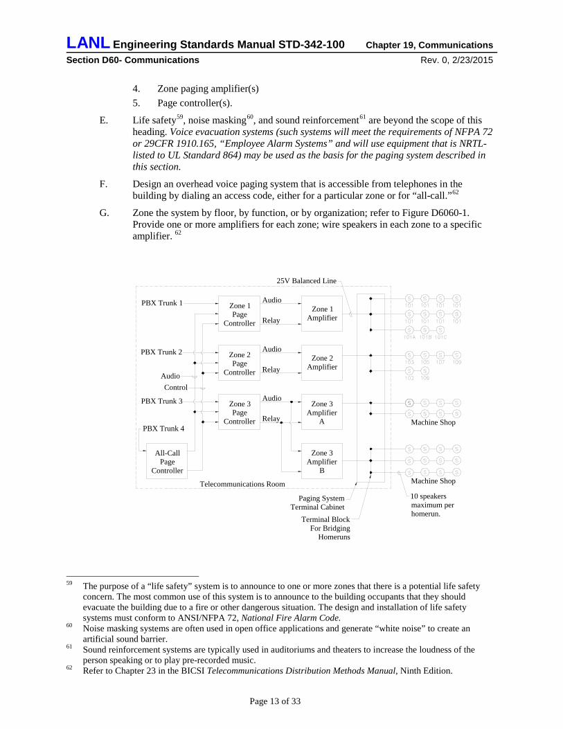
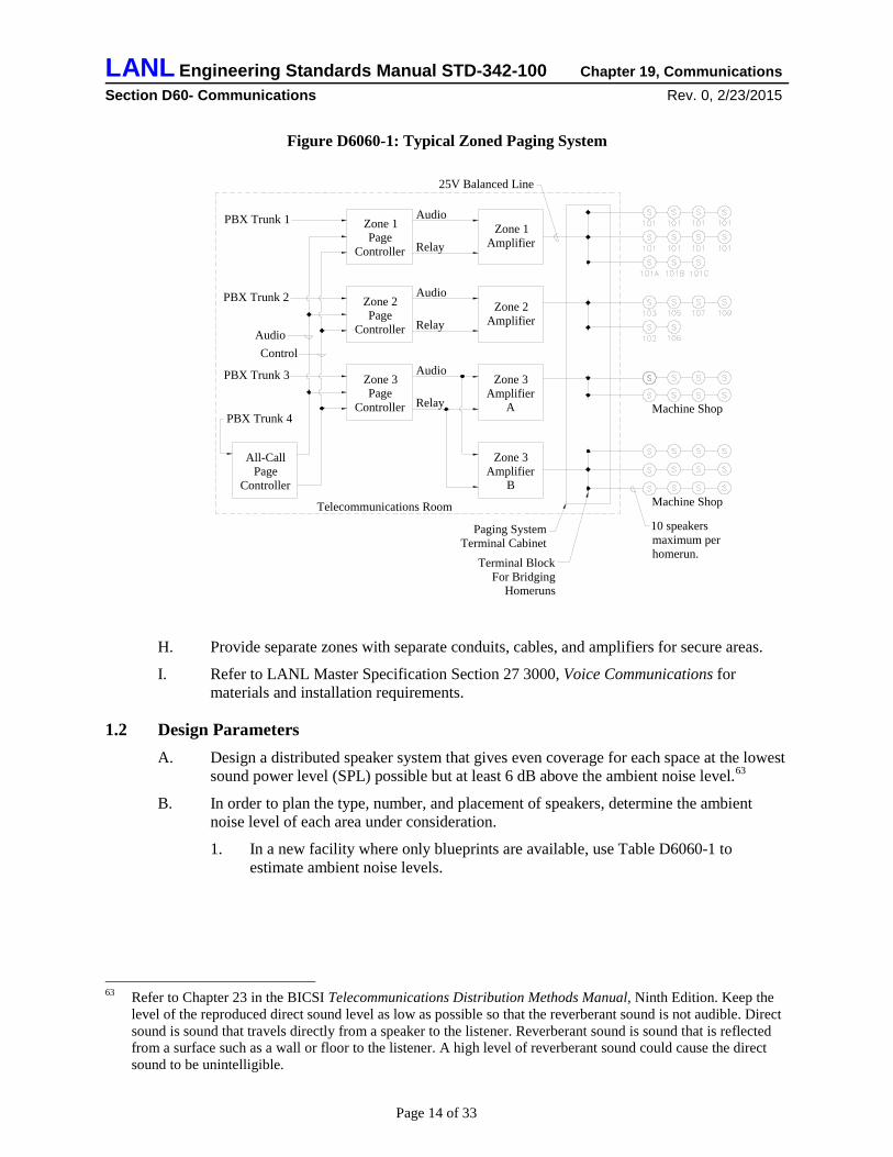
G. Zone the system by floor, by function, or by organization; refer to Figure D6060-1. Provide one or more amplifiers for each zone; wire speakers in each zone to a specific amplifier. 62
59 The purpose of a “life safety” system is to announce to one or more zones that there is a potential life safety concern. The most common use of this system is to announce to the building occupants that they should evacuate the building due to a fire or other dangerous situation. The design and installation of life safety systems must conform to ANSI/NFPA 72, National Fire Alarm Code.
60 Noise masking systems are often used in open office applications and generate “white noise” to create an artificial sound barrier.
61 Sound reinforcement systems are typically used in auditoriums and theaters to increase the loudness of the person speaking or to play pre-recorded music.
62 Refer to Chapter 23 in the BICSI Telecommunications Distribution Methods Manual, Ninth Edition.
Zone 2Page
Controller
Zone 1Page
Controller
Zone 3Page
Controller
All-CallPage
Controller
Zone 1Amplifier
Zone 2Amplifier
Zone 3Amplifier
A
Zone 3Amplifier
B
Machine Shop
Machine Shop
10 speakersmaximum perhomerun.
Telecommunications Room
PBX Trunk 1
PBX Trunk 2
PBX Trunk 3
PBX Trunk 4
AudioControl
Audio
Relay
Audio
Relay
Audio
Relay
25V Balanced Line
Paging SystemTerminal Cabinet
Terminal BlockFor Bridging
Homeruns
Page 13 of 33
LANL Engineering Standards Manual STD-342-100 Chapter 19, Communications Section D60- Communications Rev. 0, 2/23/2015
Figure D6060-1: Typical Zoned Paging System
H. Provide separate zones with separate conduits, cables, and amplifiers for secure areas.
I. Refer to LANL Master Specification Section 27 3000, Voice Communications for materials and installation requirements.
1.2 Design Parameters A. Design a distributed speaker system that gives even coverage for each space at the lowest
sound power level (SPL) possible but at least 6 dB above the ambient noise level.63
B. In order to plan the type, number, and placement of speakers, determine the ambient noise level of each area under consideration.
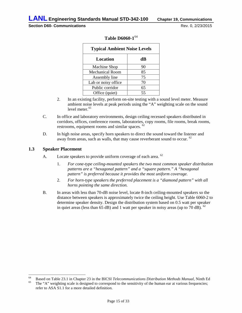
1. In a new facility where only blueprints are available, use Table D6060-1 to estimate ambient noise levels.
63 Refer to Chapter 23 in the BICSI Telecommunications Distribution Methods Manual, Ninth Edition. Keep the level of the reproduced direct sound level as low as possible so that the reverberant sound is not audible. Direct sound is sound that travels directly from a speaker to the listener. Reverberant sound is sound that is reflected from a surface such as a wall or floor to the listener. A high level of reverberant sound could cause the direct sound to be unintelligible.
Zone 2Page
Controller
Zone 1Page
Controller
Zone 3Page
Controller
All-CallPage
Controller
Zone 1Amplifier
Zone 2Amplifier
Zone 3Amplifier
A
Zone 3Amplifier
B
Machine Shop
Machine Shop
10 speakersmaximum perhomerun.
Telecommunications Room
PBX Trunk 1
PBX Trunk 2
PBX Trunk 3
PBX Trunk 4
AudioControl
Audio
Relay
Audio
Relay
Audio
Relay
25V Balanced Line
Paging SystemTerminal Cabinet
Terminal BlockFor Bridging
Homeruns
Page 14 of 33
LANL Engineering Standards Manual STD-342-100 Chapter 19, Communications Section D60- Communications Rev. 0, 2/23/2015
Table D6060-164
Typical Ambient Noise Levels
Location dB Machine Shop 90
Mechanical Room 85 Assembly line 75
Lab or noisy office 70 Public corridor 65 Office (quiet) 55
2. In an existing facility, perform on-site testing with a sound level meter. Measure ambient noise levels at peak periods using the “A” weighting scale on the sound level meter.65
C. In office and laboratory environments, design ceiling recessed speakers distributed in corridors, offices, conference rooms, laboratories, copy rooms, file rooms, break rooms, restrooms, equipment rooms and similar spaces. 62
D. In high noise areas, specify horn speakers to direct the sound toward the listener and away from areas, such as walls, that may cause reverberant sound to occur. 62
1.3 Speaker Placement A. Locate speakers to provide uniform coverage of each area. 62
1. For cone-type ceiling-mounted speakers the two most common speaker distribution patterns are a “hexagonal pattern” and a “square pattern.” A “hexagonal pattern” is preferred because it provides the most uniform coverage.
2. For horn-type speakers the preferred placement is a “diamond pattern” with all horns pointing the same direction.
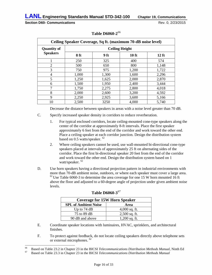
B. In areas with less than 70-dB noise level, locate 8-inch ceiling-mounted speakers so the distance between speakers is approximately twice the ceiling height. Use Table 6060-2 to determine speaker density. Design the distribution system based on 0.5 watt per speaker in quiet areas (less than 65 dB) and 1 watt per speaker in noisy areas (up to 70 dB). 62
64 Based on Table 23.1 in Chapter 23 in the BICSI Telecommunications Distribution Methods Manual, Ninth Ed 65 The “A” weighting scale is designed to correspond to the sensitivity of the human ear at various frequencies;
refer to ASA S1.1 for a more detailed definition.
Page 15 of 33
LANL Engineering Standards Manual STD-342-100 Chapter 19, Communications Section D60- Communications Rev. 0, 2/23/2015
Table D6060-266
Ceiling Speaker Coverage, Sq ft. (maximum 70-dB noise level) Quantity of
Speakers Ceiling Height
8 ft 9 ft 10 ft 12 ft 1 250 325 400 574 2 500 650 800 1,148 3 750 975 1,200 1,722 4 1,000 1,300 1,600 2,296 5 1,250 1,625 2,000 2,870 6 1,500 1,950 2,400 3,444 7 1,750 2,275 2,800 4,018 8 2,000 2,600 3,200 4,592 9 2,250 2,925 3,600 5,166 10 2,500 3250 4,000 5,740
Decrease the distance between speakers in areas with a noise level greater than 70 dB.
C. Specify increased speaker density in corridors to reduce reverberation.
1. For typical enclosed corridors, locate ceiling-mounted cone-type speakers along the center of the corridor at approximately 8-ft intervals. Place the first speaker approximately 6 feet from the end of the corridor and work toward the other end. Place a ceiling speaker at each corridor junction. Design the distribution system based on 0.5 watts/speaker. 62
2. Where ceiling speakers cannot be used, use wall-mounted bi-directional cone-type speakers placed at intervals of approximately 25 ft on alternating sides of the corridor. Place the first bi-directional speaker 20 feet from the end of the corridor and work toward the other end. Design the distribution system based on 1 watt/speaker. 62
D. Use horn speakers having a directional projection pattern in industrial environments with more than 70-dB ambient noise, outdoors, or where each speaker must cover a large area. 62 Use Table 6060-3 to determine the area coverage for one 15 W horn mounted 16 ft above the floor and adjusted to a 60-degree angle of projection under given ambient noise levels.
Table D6060-367
Coverage for 15W Horn Speaker SPL of Ambient Noise Area
Up to 74 dB 4,000 sq. ft. 75 to 89 dB 2,500 sq. ft.
90 dB and above 1,200 sq. ft.
E. Coordinate speaker locations with luminaires, HVAC, sprinklers, and architectural finishes.
F. To protect against feedback, do not locate ceiling speakers directly above telephone sets or external microphones. 62
66 Based on Table 23.2 in Chapter 23 in the BICSI Telecommunications Distribution Methods Manual, Ninth Ed 67 Based on Table 23.3 in Chapter 23 in the BICSI Telecommunications Distribution Methods Manual
Page 16 of 33
LANL Engineering Standards Manual STD-342-100 Chapter 19, Communications Section D60- Communications Rev. 0, 2/23/2015
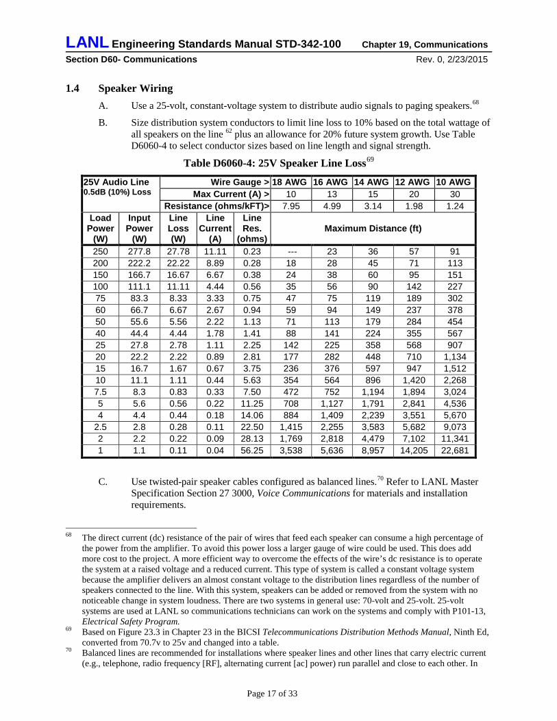
1.4 Speaker Wiring A. Use a 25-volt, constant-voltage system to distribute audio signals to paging speakers.68
B. Size distribution system conductors to limit line loss to 10% based on the total wattage of all speakers on the line 62 plus an allowance for 20% future system growth. Use Table D6060-4 to select conductor sizes based on line length and signal strength.
Table D6060-4: 25V Speaker Line Loss69
25V Audio Line 0.5dB (10%) Loss
Wire Gauge > 18 AWG 16 AWG 14 AWG 12 AWG 10 AWG Max Current (A) > 10 13 15 20 30
Resistance (ohms/kFT)> 7.95 4.99 3.14 1.98 1.24 Load
Power (W)
Input Power
(W)
Line Loss (W)
Line Current
(A)
Line Res.
(ohms) Maximum Distance (ft)
250 277.8 27.78 11.11 0.23 --- 23 36 57 91 200 222.2 22.22 8.89 0.28 18 28 45 71 113 150 166.7 16.67 6.67 0.38 24 38 60 95 151 100 111.1 11.11 4.44 0.56 35 56 90 142 227 75 83.3 8.33 3.33 0.75 47 75 119 189 302 60 66.7 6.67 2.67 0.94 59 94 149 237 378 50 55.6 5.56 2.22 1.13 71 113 179 284 454 40 44.4 4.44 1.78 1.41 88 141 224 355 567 25 27.8 2.78 1.11 2.25 142 225 358 568 907 20 22.2 2.22 0.89 2.81 177 282 448 710 1,134 15 16.7 1.67 0.67 3.75 236 376 597 947 1,512 10 11.1 1.11 0.44 5.63 354 564 896 1,420 2,268 7.5 8.3 0.83 0.33 7.50 472 752 1,194 1,894 3,024 5 5.6 0.56 0.22 11.25 708 1,127 1,791 2,841 4,536 4 4.4 0.44 0.18 14.06 884 1,409 2,239 3,551 5,670
2.5 2.8 0.28 0.11 22.50 1,415 2,255 3,583 5,682 9,073 2 2.2 0.22 0.09 28.13 1,769 2,818 4,479 7,102 11,341 1 1.1 0.11 0.04 56.25 3,538 5,636 8,957 14,205 22,681
C. Use twisted-pair speaker cables configured as balanced lines.70 Refer to LANL Master Specification Section 27 3000, Voice Communications for materials and installation requirements.
68 The direct current (dc) resistance of the pair of wires that feed each speaker can consume a high percentage of the power from the amplifier. To avoid this power loss a larger gauge of wire could be used. This does add more cost to the project. A more efficient way to overcome the effects of the wire’s dc resistance is to operate the system at a raised voltage and a reduced current. This type of system is called a constant voltage system because the amplifier delivers an almost constant voltage to the distribution lines regardless of the number of speakers connected to the line. With this system, speakers can be added or removed from the system with no noticeable change in system loudness. There are two systems in general use: 70-volt and 25-volt. 25-volt systems are used at LANL so communications technicians can work on the systems and comply with P101-13, Electrical Safety Program.
69 Based on Figure 23.3 in Chapter 23 in the BICSI Telecommunications Distribution Methods Manual, Ninth Ed, converted from 70.7v to 25v and changed into a table.
70 Balanced lines are recommended for installations where speaker lines and other lines that carry electric current (e.g., telephone, radio frequency [RF], alternating current [ac] power) run parallel and close to each other. In
Page 17 of 33
LANL Engineering Standards Manual STD-342-100 Chapter 19, Communications Section D60- Communications Rev. 0, 2/23/2015
D. Use multi-tap impedance-matching transformers to convert the 25-volt line signal to the 8-ohm speaker impedance. 62
E. Specify the identification of each end of each speaker cable.71 Use materials and installation methods described in LANL Master Specification Section 26 0553, Identification for Electrical Systems.
1.5 Speaker Raceways and Enclosures A. For new construction design speaker cables in raceway systems dedicated to speaker
cables.72
1. Use flexible metal conduit to connect to speakers mounted in accessible ceilings. 2. Use methods and materials described in LANL Master Specification Section
27 3000, Voice Communications for materials and installation requirements. 3. Make paging system raceways electrically continuous. Bond all paging system
raceways to the telecommunications ground bar.
B. For retrofit of paging systems in existing facilities use materials and installation methods that comply with NEC and TIA requirements. Avoid placing speaker wiring in close proximity to telecommunications horizontal cables.
C. Design a wall-mounted 24” x 24” x 6” hinged cover terminal cabinet below the cable tray and near the paging system equipment rack(s) in the telecommunications closet(s). Coordinate cabinet location with the LANL Telecommunications Group. Terminate the speaker conduits into the cabinet. Install terminal blocks in the cabinet for connecting and bridging speaker cables.
D. Specify ceiling-mounted cone-type speakers in metal back boxes with round perforated face metal baffles.
1.6 Paging Amplifiers A. Base the power rating of each paging zone amplifier on: 62
1. The total sum of the tap watts of each impedance matching transformer on each speaker.
2. The total sum of the power lost in the speaker distribution cabling. 3. Power reserved for 20 percent future growth. 4. Size the amplifier so it will normally be operating at about 75 percent of its rated
output.
B. Locate paging equipment in one or more of the telecommunications rooms. Design suitable equipment rack(s) to house amplifiers and page controllers.
these installations, the signals in one set of lines may be picked up by another line, causing hum, noise, or crosstalk. Balanced lines help eliminate or reduce induced noise because induced signals have the same polarity in both lines (e.g., the noise currents flow in the same direction in both lines). If these signals arrive at the load in opposition to each other and at equal amplitude, they will cancel each other out.
71 Adequate identification and records of cables will facilitate set-up, troubleshooting, and additions to the paging system.
72 Raceway systems provide support and protection for the paging system cables.
Page 18 of 33
LANL Engineering Standards Manual STD-342-100 Chapter 19, Communications Section D60- Communications Rev. 0, 2/23/2015
1.7 Acceptance Testing A. Specify acceptance testing using the following procedure: 62
1. Adjust the amplifier to 75 percent of the rated power. 2. Select an area to measure and use a sound level meter to measure the ambient noise
level. 3. Broadcast a message over the system that is representative of a normal voice page. 4. Measure the SPL of the voice page. The SPL of the voice page must be at least 6
dB higher than the ambient noise. 5. Measure the SPL in all areas within the system. 6. Adjust individual speakers by changing taps on the impedance matching
transformers.
D6060.40 Uncleared Personnel Warning Light System Note: Once another ESM chapter includes this material, it shall supersede this subsection (e.g., Ch. 9 Security Rev. 3, 2015).
1.1 General A. Design a warning light system in corridors of the secure parts of LANL facilities to alert
and remind building occupants of the presence of un-cleared or inadequately cleared visitors under escort in the area.73
B. Programmatic requirements may necessitate warning lights in additional spaces such as large computer rooms or large laboratory spaces that are not associated with corridors.
1.2 System Design A. Locate warning lights so they will be visible from all parts of every corridor in the secure
parts of facilities; place warning lights not more than 15 ft from the end of the corridor with a separation not greater than 100 ft between lights. If there is an interruption of the concentrated viewing path, such as a fire door, an elevation change, or any other obstruction, treat the area as a separate corridor.74
B. Use NRTL-listed, synchronized75 xenon strobe lights with blue lens.
C. Require labeled system control switches with indicator lamps at locations such as group offices or reception desks.
D6090 Communications Supplementary Components (Pathways, etc.) Subsection includes: Pathways, hangers and supports, conduits and back boxes, cable trays, vibration and seismic controls, identification, and grounding and bonding.
73 Un-cleared personnel warning light systems are effectively used in many LANL facilities for the purposes indicated.
74 Same spacing criteria used for uncleared personnel warning lights as for fire alarm visible alarm appliances in NFPA 72 4-4.4.2.2
75 Testing has shown that high flash rates of high intensity strobe lights can pose a potential risk of seizure to people with photosensitive epilepsy. To reduce this risk, more than two visible appliances are not permitted in any field of view unless they are separated by at least 55 ft. or unless their flashes are synchronized.
Page 19 of 33
LANL Engineering Standards Manual STD-342-100 Chapter 19, Communications Section D60- Communications Rev. 0, 2/23/2015
1.1 Backbone and Entrance Pathways A. Design a minimum of two telecommunications76 entrance conduits (plus security77
service entrance conduits as described under the PTS heading in ESM Chapter 18) from the entrance telecommunications room to the point of connection to the network; coordinate design for each project with the LANL Telecommunications Group. Point of connection to the network will be either a maintenance hole (MH) or a telephone pedestal.
1. Design the number and size of entrance conduits based on the anticipated number and type of telecommunications circuits required in the building. In office buildings, this anticipated number is often calculated as one entrance pair per 100 ft2 of usable office space. Coordinate with the LANL Telecommunications Group.
2. Terminate the conduits in the left-rear corner of the telecommunications room and adjacent to the left wall.78
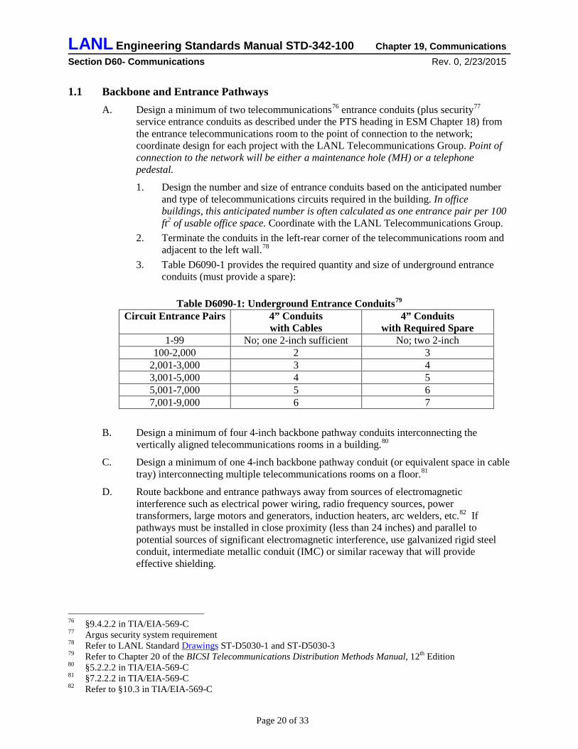
3. Table D6090-1 provides the required quantity and size of underground entrance conduits (must provide a spare):
Table D6090-1: Underground Entrance Conduits79
Circuit Entrance Pairs 4” Conduits with Cables
4” Conduits with Required Spare
1-99 No; one 2-inch sufficient No; two 2-inch 100-2,000 2 3
2,001-3,000 3 4 3,001-5,000 4 5 5,001-7,000 5 6 7,001-9,000 6 7
B. Design a minimum of four 4-inch backbone pathway conduits interconnecting the vertically aligned telecommunications rooms in a building.80
C. Design a minimum of one 4-inch backbone pathway conduit (or equivalent space in cable tray) interconnecting multiple telecommunications rooms on a floor.81
D. Route backbone and entrance pathways away from sources of electromagnetic interference such as electrical power wiring, radio frequency sources, power transformers, large motors and generators, induction heaters, arc welders, etc.82 If pathways must be installed in close proximity (less than 24 inches) and parallel to potential sources of significant electromagnetic interference, use galvanized rigid steel conduit, intermediate metallic conduit (IMC) or similar raceway that will provide effective shielding.
76 §9.4.2.2 in TIA/EIA-569-C 77 Argus security system requirement 78 Refer to LANL Standard Drawings ST-D5030-1 and ST-D5030-3 79 Refer to Chapter 20 of the BICSI Telecommunications Distribution Methods Manual, 12th Edition 80 §5.2.2.2 in TIA/EIA-569-C 81 §7.2.2.2 in TIA/EIA-569-C 82 Refer to §10.3 in TIA/EIA-569-C
Page 20 of 33
LANL Engineering Standards Manual STD-342-100 Chapter 19, Communications Section D60- Communications Rev. 0, 2/23/2015
E. Specify a woven polyester pull tape (1,200-lb test) with stamped footage markings pulled into each backbone and entrance pathway conduit and all innerduct and tied off at each end.83
F. Require sealing the building end of each entrance pathway to prevent rodents, water, or gases from entering the building or MH. Use rubber conduit plugs or duct sealer, depending upon the conditions. Reseal conduits after cable is placed in them.84
G. Specify identification of backbone and entrance pathways in accordance with 27 1000, Structured Cabling; generate records acceptable to the LANL Telecommunications Group.106
H. Use materials and installation methods described in LANL Master Specification Section 26 0553, Identification for Electrical Systems.
1.2 Horizontal Pathways A. Design telecommunications horizontal pathways that meet the requirements in TIA-569,
the NEC, and this chapter of the LANL Engineering Standards Manual.
B. Design telecommunications horizontal pathways to have the following characteristics:
1. Suitable for all telecommunications media recognized in TIA-568.85 2. Allow at least three cable runs per telecommunications outlet. 3. Accommodate cabling changes. 4. Minimize occupant disruption when horizontal pathways are accessed. 5. Facilitate ongoing maintenance of horizontal cabling. 6. Accommodate future additions to and changes in cabling, equipment, and services 7. Provide for at least 20% future growth. 8. Limit raceway fill as follows86:
Less than 50 ft between pulling points and only one bend: 40 percent fill.
More than 50 ft between pulling points or two 90-degree bends: 31 percent fill.
C. Use one or more of the following horizontal pathways to provide a telecommunications distribution system that is appropriate for the building use and strikes an acceptable balance between greatest flexibility and lowest life-cycle cost:87
1. Underfloor system (underfloor duct or cellular floor system) 2. Access floor 3. Conduit 4. Cable tray 5. Wireway 6. Perimeter raceway 7. Furniture pathways.
83 Footage markers facilitate ordering the correct length cable 84 §5.1.1.2.8 in TIA/EIA-758B 85 §4.1.4 in TIA/EIA-569-C 86 Table 4.4-1 in TIA/EIA-569-C 87 §4.1 in TIA/EIA-569-C
Page 21 of 33
LANL Engineering Standards Manual STD-342-100 Chapter 19, Communications Section D60- Communications Rev. 0, 2/23/2015
D. Design underfloor pathway systems (underfloor duct or cellular floor system) to meet NEC requirements88 and the design guidance in TIA-569.89
E. Design access floor pathway systems to meet NEC requirements,90 the design guidance in TIA-569,91 and the following requirements:
1. For general office areas, design the raised floor surface to be 8 inches high or higher.92
2. For computer or control room environments where the plenum is used for HVAC, design the finished floor to be 12 inches high or higher.77
3. Use cable trays, wireways, and dedicated routes so telecommunications cables in an access floor pathway can be placed in a manner that provides sufficient space for service personnel to stand on the structural floor without risk of damaging cable.77
4. Require the following minimum clearances above and below cable trays and wireways: • 2 inches of free space between the top of the wireway or the cable tray side
rails and the underside of the stringers. • 1 inch of free space between the bottom of the wireway or the cable tray side
rails and the structural floor for power conduits.
F. Use conduit pathway for individual telecommunications outlets and for furniture pathway/building interfaces. Provide conduit pathway systems that meet NEC requirements, the design guidance in TIA-569,93 and the following requirements:
1. Install conduit runs with no more than 100 feet between pull points.94 2. Install conduit runs with no more than 180 degrees of bends between pull points.
Install a pull box at any reverse bend.95 3. For conduits 2 inches and smaller the inside radius of conduit bends must not be
less than 6 times the internal diameter of the conduit.96 For conduits larger than 2 inches the inside radius of conduit bends must not be less than 10 times the internal diameter of the conduit. Do not use conduit bodies in any conduit pathway system.Error! Bookmark not defined.
4. Select conduit sizes on the following basis: • Less than 50 ft between pulling points and only one bend: 40 percent fill. • More than 50 ft between pulling points or two 90-degree bends: 31 percent
fill97.
88 NEC Articles 800.110 89 §4.2 in TIA/EIA-569-C 90 NEC Article 645 91 §4.3 in TIA/EIA-569-C 92 Chapter 5 in the BICSI Telecommunications Distribution Methods Manual, 12th Ed. Although ANSI/TIA/EIA-
569-C specifies 6 in as the minimum finished height for standard-height access floors, at least 8 in is necessary to provide sufficient space for cable trays and other means of cable management.
93 §4.4 in TIA/EIA-569-C 94 §4.4.2.2 in TIA/EIA-569-C 95 §4.4.2.3.1 in TIA/EIA-569-C 96 §4.4.2.3.2 in TIA/EIA-569-C 97 Telecommunications cables are much more fragile than standard building wire. FPN No, 1 to Table 1 in
Chapter 9 of the NEC states that for certain conditions a lesser conduit fill should be considered. Note 2 to
Page 22 of 33
LANL Engineering Standards Manual STD-342-100 Chapter 19, Communications Section D60- Communications Rev. 0, 2/23/2015
• Minimum size: 1 inch unless specified otherwise 5. Specify an individual 1-inch98 conduit from each wall-mounted
telecommunications outlet to a telecommunications cable tray or to the telecommunications room.
6. Design individual conduits from each furniture pathway/building interface to a telecommunications cable tray or to the telecommunications room. Size conduits based on 3 cables per workstation.
7. Terminate metallic telecommunications conduits using an insulated throat fitting or an insulating bushing.99
8. Use materials and installation methods described in LANL Master Specifications Section 26 0533, Raceways and Boxes for Electrical Systems.
G. Use dedicated cable tray systems to distribute horizontal cables from the telecommunications room(s) to locations near the outlets.100 Provide cable tray pathway systems that meet NEC requirements, the design guidance in TIA-569,101 and the following criteria:
1. For general office buildings, size cable tray based on 1 sq. in. of cable tray per 100 sq. ft. of useable floor area served.102
2. Limit cable initial tray fill ratio to 41.6%.103 3. Require not less than 12 inches access headroom above and to one side of all
telecommunications cable trays.104 Careful design and installation coordination with the building structure, HVAC ductwork, sprinkler piping, and luminaires is required to maintain the required 12-inch clearance. Consider developing “plan and profile” type drawings for each cable tray to assure meeting this requirement.
4. Use cable tray with a maximum rung spacing of 6 inches to reduce cable sag and the possibility of long-term cold creep insulation damage to telecommunications cables.
5. Do not allow any wiring system other than telecommunications in any telecommunications cable tray.Error! Bookmark not defined.
6. Refer to Section D5090 of ESM Chapter 7 for cable tray design requirements. 7. Use materials and installation methods described in LANL Master Specifications
Section 26 0536, Cable Trays for Electrical Systems.
Table 4.4-1 in TIA/EIA-569-C states that the number of cables that can be installed in a conduit is limited by the allowed maximum pulling tension of the cables.
98 Refer to table 4.4-1 in TIA/EIA-569-C. A 1-inch conduit provides capacity for up to 3 Category 6A 4-pair UTP plenum-rated cables having a 0.26 inch outside diameter.
99 §4.4.3.1 in TIA/EIA-569-C 100 A cable tray concealed above corridor lift-out ceilings provides an economical and flexible way to
accommodate evolving communications needs. 101 Refer to §4.5 in TIA/EIA-569-C. 102 Refer to §4.5.3 in TIA/EIA-569-C. 103 §4.5.3 in TIA/EIA-569-Csets an absolute maximum cable tray fill ratio of 50%. Limiting the initial fill ratio to
41.6% provides for 20% future growth. 104 §4.5.6 in TIA/EIA-569-C
Page 23 of 33
LANL Engineering Standards Manual STD-342-100 Chapter 19, Communications Section D60- Communications Rev. 0, 2/23/2015
H. Route horizontal pathways away from sources of electromagnetic interference such as electrical power wiring, radio frequency sources, power transformers, large motors and generators, induction heaters, arc welders, fluorescent and HID luminaires, etc.105
I. Identify horizontal pathways in accordance the LANL Telecommunications Group.106 Use materials and installation methods described in LANL Master Specification Section 26 0553, Identification for Electrical Systems and 27 1000, Structured Cabling.
J. For retrofit of pathways for horizontal cables in existing buildings use materials and installation methods that comply with the NEC and meet TIA/EIA requirements.
1.3 Furniture Pathways A. Comply with TIA-569 Addendum for furniture pathways.107
B. Comply with TIA-569 on “Separation from EMI Sources (e.g., Rev. C Section 10.3).”
C. Specify separation from electric light and power conductors as required in NEC Article 800108.
D. Use one of the two following options to obtain the required separation:
1. Metallic divider bonded to ground between power and telecommunications cables. 2. Dedicated separate pathway for telecommunications cables. Guidance: Some
furniture system manufacturers offer panel systems with a telecommunications pathway on top of the panels.
3. Power conductors enclosed in grounded metallic raceway or cable sheath.
1.4 Cables A. Specify three LANL-furnished horizontal cables109 to each telecommunications outlet.
Coordinate with the LANL Telecommunications Group to determine the exact types and mix of horizontal cables that will be provided.
1. Copper horizontal cable will be UL listed as type CMP (plenum-rated), 4-pair, 23-gauge, Category 6A, unshielded twisted pair (UTP) cable with a maximum outside diameter of 0.354 inches.
2. Fiber optic horizontal cable will be UL listed as type OFNP (plenum-rated) cable with an outside diameter of approximately 0.24 inches.Error! Bookmark not defined.
3. The installing Subcontractor shall terminate all Category 6A horizontal cables. 4. LANL will terminate the fiber optic horizontal cables.
B. Specify LANL-furnished backbone cables to interconnect the telecommunications rooms and server equipment rooms. Coordinate with the LANL Telecommunications Group to determine the sizes, types, and mix of backbone cables that will be provided.
1. Copper backbone cable will be ARMM (24 AWG) cable, UL listed as type CMR.Error! Bookmark not defined. (Note that this cable is not plenum-rated.)
105 §10.3 in TIA/EIA-569-C 106 LANL method differs from TIA/EIA-606B 107 TIA/EIA-569-C Addendum 2 addresses furniture pathway planning, fill factors, capacity, access, bend radius,
and power/telecommunications separation requirements. 108 NEC Section 800.133(a)(2) 109 The 3 ports on the work area outlet are for telephone, computer network interface, and printer network interface
or spare.
Page 24 of 33
LANL Engineering Standards Manual STD-342-100 Chapter 19, Communications Section D60- Communications Rev. 0, 2/23/2015
2. Fiber optic backbone cable will be UL listed as type OFNR, tight-buffered fiber-optic cable with a mixture of single-mode and multi-mode fibers.Error! Bookmark not
defined. 3. LANL will terminate all backbone cables.
C. Cable installers must have the following minimum qualifications:
1. Category 6A horizontal cables: BICSI Registered Installer Level 2 or equivalent certification plus successful completion of Systimax Installer Training that includes installation and termination of Category 6A cable; experience installing and terminating Category 6A cables on at least 2 previous projects.110
2. Fiber optic horizontal cables, all backbone cables: BICSI Registered Installer Level 2 or equivalent certification; experience installing backbone and fiber optic cables on at least two previous projects. 110
D. Specify labels on cables, ports, and panels of fiber housings in racks per LMS Section 27 1000 Structured Cabling. Generate records acceptable to the LANL Telecommunications Group.
E. Specify testing of the installed and terminated Category 6A horizontal cables in accordance with TIA-568; provide Fluke LinkWare test result outputs in native electronic file and pdf formats for each cable to the LANL Telecommunications Group for review and acceptance.
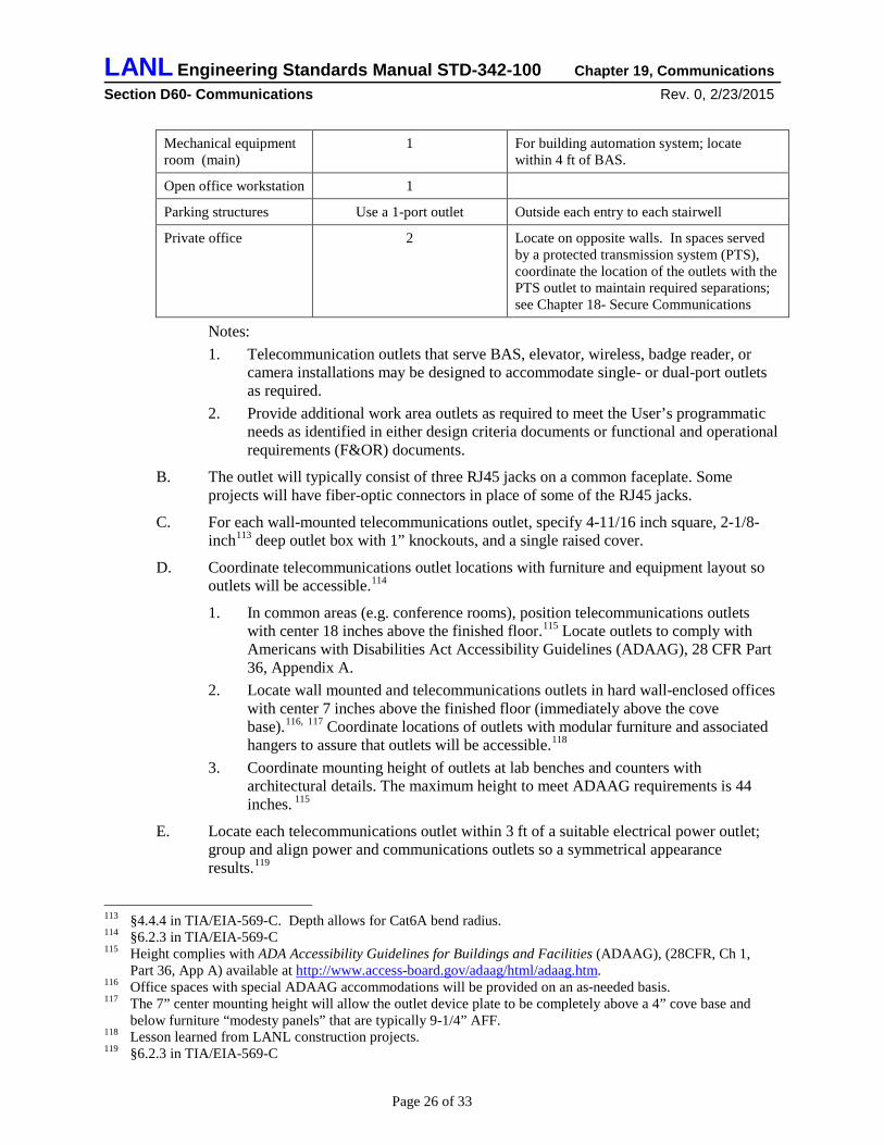
1.5 Outlets A. Locate communication outlets per Table D6090-2: 111
Table D6090-2 Communication Outlet Requirements Location Number of 3-port Outlets112 Notes
Badge reader 1 For a wall mounted telephone
Break room 1 For a wall-mounted telephone
Conference room 2 One at front of room and second centered in floor for table’s telecon phone
Copier room 2 One located within 4 ft of copier
Electrical room (main) 1 For electrical metering; locate within 4 ft of meter.
Elevator equipment room
1 For elevator equipment
110 BICSI, a not-for-profit telecommunications association, is a worldwide resource for technical publications, training, conferences, and registration programs for low-voltage cabling distribution design and installation. BICSI is the only nationally recognized organization that offers a vendor independent comprehensive testing and registration program for both installers and designers. Installer registration is available at three levels: Installer Level 1 (minimum of six months experience), Installer Level 2 (minimum of two years’ experience) and Installer Technician Level (minimum of five years’ experience). Written and hands-on examinations must be successfully completed. Registration exams are offered at all levels. The required minimum work experience is necessary to sit for each exam. Successful completion of these exams reinforces and documents that BICSI registered installers have the background, knowledge, and skills needed to work effectively.
111 Refer to §6.2.2 in TIA/EIA-569-C. 112 Limiting to 3 ports/cables allows use of 1” conduit (vs. 1-1/4”)
Page 25 of 33
LANL Engineering Standards Manual STD-342-100 Chapter 19, Communications Section D60- Communications Rev. 0, 2/23/2015
Mechanical equipment room (main)
1 For building automation system; locate within 4 ft of BAS.
Open office workstation 1
Parking structures Use a 1-port outlet Outside each entry to each stairwell
Private office 2 Locate on opposite walls. In spaces served by a protected transmission system (PTS), coordinate the location of the outlets with the PTS outlet to maintain required separations; see Chapter 18- Secure Communications
Notes: 1. Telecommunication outlets that serve BAS, elevator, wireless, badge reader, or
camera installations may be designed to accommodate single- or dual-port outlets as required.
2. Provide additional work area outlets as required to meet the User’s programmatic needs as identified in either design criteria documents or functional and operational requirements (F&OR) documents.
B. The outlet will typically consist of three RJ45 jacks on a common faceplate. Some projects will have fiber-optic connectors in place of some of the RJ45 jacks.
C. For each wall-mounted telecommunications outlet, specify 4-11/16 inch square, 2-1/8-inch113 deep outlet box with 1” knockouts, and a single raised cover.
D. Coordinate telecommunications outlet locations with furniture and equipment layout so outlets will be accessible.114
1. In common areas (e.g. conference rooms), position telecommunications outlets with center 18 inches above the finished floor.115 Locate outlets to comply with Americans with Disabilities Act Accessibility Guidelines (ADAAG), 28 CFR Part 36, Appendix A.
2. Locate wall mounted and telecommunications outlets in hard wall-enclosed offices with center 7 inches above the finished floor (immediately above the cove base).116, 117 Coordinate locations of outlets with modular furniture and associated hangers to assure that outlets will be accessible.118
3. Coordinate mounting height of outlets at lab benches and counters with architectural details. The maximum height to meet ADAAG requirements is 44 inches. 115
E. Locate each telecommunications outlet within 3 ft of a suitable electrical power outlet; group and align power and communications outlets so a symmetrical appearance results.119
113 §4.4.4 in TIA/EIA-569-C. Depth allows for Cat6A bend radius. 114 §6.2.3 in TIA/EIA-569-C 115 Height complies with ADA Accessibility Guidelines for Buildings and Facilities (ADAAG), (28CFR, Ch 1,
Part 36, App A) available at http://www.access-board.gov/adaag/html/adaag.htm. 116 Office spaces with special ADAAG accommodations will be provided on an as-needed basis. 117 The 7” center mounting height will allow the outlet device plate to be completely above a 4” cove base and
below furniture “modesty panels” that are typically 9-1/4” AFF. 118 Lesson learned from LANL construction projects. 119 §6.2.3 in TIA/EIA-569-C
Page 26 of 33
LANL Engineering Standards Manual STD-342-100 Chapter 19, Communications Section D60- Communications Rev. 0, 2/23/2015
F. At the fire alarm control panel, install a 6” x 6” x 4” box.
1. Extend a ¾-inch conduit to the nearest telecommunications room. 2. Extend a ¾-inch conduit to the fire alarm control panel.
1.6 Grounding A. Design telecommunications grounding to comply with TIA-607120 and the NEC.
B. Design a telecommunications bonding backbone conductor that interconnects the telecommunications grounding busbar in each telecommunications room, each server equipment room, and each telecommunications equipment rack not located in a telecommunications room.121 Use 4/0 AWG conductor with 600V insulation and connected with two-hole hydraulically compressed cable lugs.122
C. Locate a telecommunications main grounding bus bar in the entrance telecommunications room, each “satellite” telecommunications room, each server equipment room, and at each telecommunications equipment rack not located in a dedicated room.123
1. Use a NEMA pattern (1.25 inch x 1.25 inch) pre-drilled electro-tinplated copper bar that is 1/4 inch thick, 4 inches wide, minimum 12 inches long plus additional length as required to land the required cables plus at least 20% future growth. Mount busbar on 2-inch standoff insulators. Label ground bars appropriately (TMGB, TGB, or TB).
2. Bond the telecommunications main grounding bus bar to the building electrical system main electrode ground bar using a dedicated 4/0 AWG conductor with 600V insulation and connected with two-hole, hydraulically compressed, cable lugs.124
3. Terminate the ground cable in telecommunications duct bank(s) to the ground bar in the entrance telecommunications room(s) using hydraulically compressed cable lugs.
4. If the building has a metal frame, also bond the bus bar to the nearest structural steel using a 6 AWG conductor with crimp-on cable lugs.
D. Do not place grounding or bonding conductors in ferrous metallic conduit.125
E. Label, identify, and color code each bonding and grounding conductor per Specification Section 26 0553 Identification for Electrical Systems.126
F. Effectively ground and bond all metallic telecommunications raceways and cable trays.127
1. Bond the telecommunications cable tray to each telecommunications ground bar with minimum 6 AWG using crimp-on lugs.
73 Chapter 5 in the BICSI Telecommunications Distribution Methods Manual, 12th Edition 120 ANSI-J-STD 607-B is the telecommunications standard that addresses telecommunications grounding and
bonding from a functional perspective. It is used in concert with ANSI/EIA/TIA-568 and ANSI/EIA/TIA-569. 121 §5.3 in ANSI-J-STD 607-B 122 This is the same grounding conductor size and connection method used for electrical power systems at LANL.
Used on telecommunications systems to simplify tooling and inspections. 123 §5.4 and §5.5 in ANSI-J-STD 607-B 124 §5.2 in ANSI-J-STD 607-B 125 §5.1.4 in ANSI-J-STD 607-B 126 §5.1.5 in ANSI-J-STD 607-B 127 NEC Section 250.96
Page 27 of 33
LANL Engineering Standards Manual STD-342-100 Chapter 19, Communications Section D60- Communications Rev. 0, 2/23/2015
2. Install a 6 AWG equipment grounding conductor in each cable tray and bond to every section using NRTL listed cable tray bonding clamps.128
3. Bond metal raceways entering the telecommunications room and containing telecommunications cables to the telecommunications ground bar. • Use 12 AWG conductor for individual conduits 1” and smaller. • Use 6 AWG conductors for multiple conduits or individual conduits larger
than 1”. 4. Connect metallic conduits to cable tray with approved cable tray to conduit clamps. 5. Isolated sections of metallic raceway or cable tray will be considered effectively
grounded when clamped or bonded to the metal building structure. 6. In buildings without metal structure, install a minimum 12 AWG green insulated
ground wire with the telecommunications cables to bond isolated sections of metallic raceway.
G. Use materials and installation methods described in LANL Master Specification Section 26 0526, Grounding and Bonding for Electrical Systems.
1.7 IEEE 802.11 Wireless Systems129 The overwhelming majority of new and renovated buildings will have wired networks (“landlines”) as noted earlier in this document. Wireless networks are not a replacement for a wired network; they offer an alternative type of service from wired service with respect to portability. Wireless service, indoor and outdoor, is an extension of the wired network for general-purpose network needs. It enables applications that require the mobility offered by wireless, but which are not necessarily equivalent in bandwidth, reliability, or security versus wired connections.
1.7.1 Definitions
A. Access point: A device that is a RF transmitter and receiver to facilitate wireless communications.
B. Cell: The area in which the wireless access point can be located.
C. Coverage zone: The area in which the wireless access point provides a signal that is strong enough to support communications.
D. dBm: Decibel in relation to milliwatts of power
E. Fade Margin: the level of desired signal above what is required
F. Fresnel zone: a 3-dimensional shape of concentric ellipsoids that surround the visual line of sight between two antennas
G. Link budget: the calculation of Received Power (dBm) = Transmitted Power (dBm) + Gains (dBm) – Losses (dBm)
H. Signal-to-Noise Ratio: Signal level minus the noise level measured in dbm
1.7.2 Acronyms
A. AP - Access point
128 Recommended practice in §8.4 of IEEE 1100-1999 129 Adapted from IEEE 802.11 Wireless Design and BISCI Wireless Design Reference Manual, 3rd Ed 2008
Page 28 of 33
LANL Engineering Standards Manual STD-342-100 Chapter 19, Communications Section D60- Communications Rev. 0, 2/23/2015
B. HD – High density
C. LANL – Los Alamos National Laboratory
D. PoE – Power over Ethernet
E. RF – Radio frequency
F. SAR - Specific absorption rate
G. SNR - Signal-to-noise ratio
H. TO – Telecommunications outlet
I. WLAN – Wireless local area network
1.7.3 General
A. Wireless Network(s) shall meet all applicable regulatory agency standards and shall be installed to minimize radio frequency interference.
B. Use TIA Telecommunications Systems Bulletin TSB-162 (and amendments to), “Telecommunications Cabling Guidelines for Wireless Access Points”, as a guideline for installation methods.
C. Access Points and all associated components shall be installed per manufacturer’s specifications.
D. Access point and antenna selection shall utilize manufacturer’s “AP and Antenna Selection Decision Tree” or similar guidance for best practice based on each wireless design.
E. Follow U.S. SAR regulations which state a minimum of 6-inch clearance between WLAN antennas and the human body must be maintained.
F. Wireless coverage areas are impacted by a number of factors such as:
• Building materials (concrete, sheetrock, wood, steel, etc.)
• Building configuration (closed, semi-closed, or open space)
• Building furnishings (cabinets, partitions, furniture, etc.)
• Existing radio frequencies operating in the same frequency spectrum (microwave ovens, cordless telephones, RF generating lab equipment, etc.)
• Occupant density (conference rooms, lecture halls, lobby area, etc.)
• In the case of outdoor wireless: distance, Fresnel zone size, topography, terrain, path obstacles such as trees, buildings and water as well as environmental effects can also be factors.
G. The LANL Telecommunications Group will document the WLAN configuration which will assist the network managers in tracking use of the radio spectrum.
1.7.4 Wireless Design Input
An RF site survey and design or simulation must be made to ensure adequate coverage and capacity for both indoor and outdoor environments. Perform the following with each wireless design:
A. Manual site survey
Page 29 of 33
LANL Engineering Standards Manual STD-342-100 Chapter 19, Communications Section D60- Communications Rev. 0, 2/23/2015
B. Predictive site survey
C. Spectrum analysis
1.7.5 Wireless Design
A. Capacity design goals will be defined with customer input. Goals will include total number of devices and minimum bandwidth per device.
B. Coordinate service and interior distribution requirements with the LANL Telecommunications Group.
C. Coverage and capacity zones will be designed with a minimum of -70dbm received signal strength and a -25dbm minimum SNR.
D. The antenna mounting locations are to have no obstructions between the front of the antennas and the intended wireless clients.
E. Designs must show antennas mounted with built-in down-tilt flat against the ceiling or floor so that the beam is vertical.
F. Designs must not mix mounting strategies in a room. When designing adjacent HD WLANs, the same strategy, overhead, side, or picocell must be used throughout the same room.
G. When designing for side coverage strategy, design must reference manufacture spacing requirements for APs with integrated antennas and for AP spacing in a closet with antennas remotely located.
H. If external antennas are used, mount AP as close to their antennas as possible. Use coaxial cable that meets manufacturer specifications to connect to remote antenna to AP when they must be a distance away (per manufacturer specifications) from each other.
I. Perform a link budget analysis for each point-to-point and point-to-multi-point outdoor link to determine that the final received signal amplitude is above the receiver sensitivity threshold of the receiver radio.
J. Each link budget analysis must include a fade margin within the range of 20db to 30db for minimum link reliability.
K. Fresnel zone obstructions shall not exceed more than 20% into the 1st zone for all outdoor links.
1.7.6 Wireless Installation and Testing
A. Use the materials and installation methods described in LANL Master Specifications Section 27 1000, Structured Cabling.
B. The LANL Telecommunications Group will furnish access points and antennas as GFE.
C. CAT5E, CAT6A, or optical fiber cables, and head-end switching to provide power and Ethernet to the access points may be furnished and installed in the entrance telecommunications room by the LANL Telecommunications Group.
D. Run horizontal cable from each access point /air monitor outlet to the telecommunications room. All wireless horizontal cabling will be orange as well as cross-connects from the horizontal to the telecommunication room equipment patch cords.
Page 30 of 33
LANL Engineering Standards Manual STD-342-100 Chapter 19, Communications Section D60- Communications Rev. 0, 2/23/2015
E. Terminate wireless horizontal cabling on a two-port, surface-mount outlet box mounted above the drop ceiling or in general ceiling area. The patch cords and horizontal cabling connected to the access point shall not exceed 100 meters.
F. Patch cords shall connect the outlet port to a designated RJ-45 port located on the access point or air monitor and not exceed 6 feet in length.
G. Guidance: AP placement should not exceed 14 feet above finished floor when installing access point/air monitor with built-in antennas.
H. In general, cell coverage zones should be 60 feet or less in diameter and placed with overlapping coverage.
I. Antenna adjustment on the access point/air monitor may be necessary for proper operation. Refer to manufacturer’s specifications.
J. Perform a “channel link test” on all ports made active for use by an access point or air monitor.
K. APs shall connect to PoE switches for power and network connectivity. If PoE is not available to AP location, an external power source can be used.
L. Outdoor antenna connectors must be weatherproofed.
M. External antennas must be grounded. Ground connection must be complete before connecting power. Grounding must meet LANL electrical codes.
N. On external installations, the need for lightning protection must be determined (ref. NFPA 780).
O. All cables are to be tested and test results documented.
P. Throughput testing shall be performed using LANL Telecommunications Group approved software and testing method.
Q. Perform a “channel link test” on all ports made active for use by an access point or air monitor.
APPENDIX A Administrative Access Control System (e.g., Apollo) (D7010.10) Note: Once another ESM chapter includes this material, it shall supersede this Appendix (expected in Ch. 9 Security Rev. 3, 2015).
1.1 General A. Design administrative access control (badge reader) system as described in this section
and as required by the User’s programmatic needs. Coordinate requirements with the LANL Security Systems Group.
B. Design an administrative access control system described under this heading in any of the following situations:130
1. The building or system exterior is located in a “public domain” and the interior is classified as a “property protection area.” (A “property protection area” is
130 Criteria provided by the LANL Security Systems Group.
Page 31 of 33
LANL Engineering Standards Manual STD-342-100 Chapter 19, Communications Section D60- Communications Rev. 0, 2/23/2015
intended to protect against damage, destruction, or theft of Government property. A “property protection area” is defined as one in which personnel are not required to have a clearance or be escorted but must pass through a guard or access control point. A “public domain” is an area where un cleared persons have unescorted access and uncontrolled access. This applies even if it is on Government property.)
2. The building or system exterior located in a “limited area” or above, and the interior is classified as a “limited area” or above. (a “limited area” is defined as one in which personnel access is limited to persons possessing a final, government issued security clearance or are under escort by an individual possessing final, Government-issued security clearance. A “limited area”, through physical barriers and controlled access, is intended to protect classified material or Category III SNM.)
3. The User requires automatic entrance and exit control and logging for a room or area.
4. Doors controlled by administrative access control systems typically include: Each exterior door or set of doors except at vestibules install the access
controls on the interior door or set of doors. Electrical room doors. Mechanical room doors. Telecommunications room doors. Server room doors.
C. The LANL Security Systems Group will furnish and install badge readers, power supplies, and control equipment.
D. Raceways, boxes, cables, and electric strikes or panic bars will be furnished and installed by the construction contractor; refer to Section 28 1321, Administrative Access Control System Rough-In.
E. The system controller will be furnished and installed by the LANL Security Systems Group. Wiring from the controller to the terminal box in the telecommunications room will be furnished and installed by the LANL Security Systems Group.
F. Specify electric door strikes and exit hardware that will be compatible with the administrative access control system.
1. Operating voltage: 12/24 VDC. 2. Door strike current: 0.5 amperes maximum. 3. Exit hardware current: 0.5 amperes maximum.
G. Time and funding will be necessary for the installation of access control system controller, performance testing, and field quality assurance activities by the LANL Security Systems Group. The Project should obtain a definitive cost estimate and schedule from the LANL Security Systems Group.
H. Refer to LANL Master Specification Section 28 1321, Administrative Access Control System Rough-In for materials and installation requirements.
1.2 System Design A. Specify a suitably sized wireway in the entrance telecommunications room.
B. Specify a 3-inch conduit from the wireway to the access control system equipment rack.
Page 32 of 33
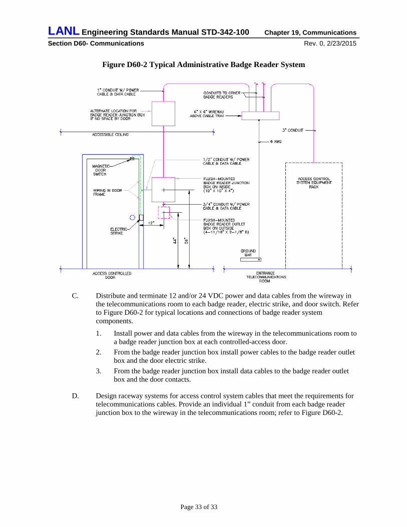
LANL Engineering Standards Manual STD-342-100 Chapter 19, Communications Section D60- Communications Rev. 0, 2/23/2015
Figure D60-2 Typical Administrative Badge Reader System
C. Distribute and terminate 12 and/or 24 VDC power and data cables from the wireway in
the telecommunications room to each badge reader, electric strike, and door switch. Refer to Figure D60-2 for typical locations and connections of badge reader system components.
1. Install power and data cables from the wireway in the telecommunications room to a badge reader junction box at each controlled-access door.
2. From the badge reader junction box install power cables to the badge reader outlet box and the door electric strike.
3. From the badge reader junction box install data cables to the badge reader outlet box and the door contacts.
D. Design raceway systems for access control system cables that meet the requirements for telecommunications cables. Provide an individual 1” conduit from each badge reader junction box to the wireway in the telecommunications room; refer to Figure D60-2.
Page 33 of 33