Landpro 08.08.11-11.0010.0140 Soils Report R1 Soils ... B2 Sieve Analysis B3 pH, Resistivity,...
62
Geotechnical Investigation Revision 1 Landpro 8159-8162 Site APN 0466-181-59, 60, 61 & 62 Helendale, CA Prepared For: Sunlight Partners 4215 East McDowell Rd. #212 Mesa, AZ. 85215 Attn: Jason Ellsworth MEC No: 12.0010.0140 August 8, 2012
-
Upload
hoangnguyet -
Category
Documents
-
view
215 -
download
0
Transcript of Landpro 08.08.11-11.0010.0140 Soils Report R1 Soils ... B2 Sieve Analysis B3 pH, Resistivity,...

Geotechnical Investigation Revision 1 Landpro 8159-8162 Site APN 0466-181-59, 60, 61 & 62 Helendale, CA
Prepared For: Sunlight Partners 4215 East McDowell Rd. #212 Mesa, AZ. 85215 Attn: Jason Ellsworth
MEC No: 12.0010.0140 August 8, 2012

August 8 Sunlight4215 EasMesa, AZAttn: Jas Re: G
AH
Mr. Ellsw
In accordthe abovour field The invedevelopmsite, andwithin thi We anticphases o Sincerely Merrell E Brad S. MRCE 494
, 2012
t Partners Lst McDowellZ. 85215 son Ellsworth
GeotechnicaAPN 0466-18Helendale, C
worth,
dance with ye-referencedand laborato
stigation wament of this presents as project site
cipate the enof this projec
y,
Engineering
Merrell, PE, 423 Exp. 09/
LLC Rd. #212
h
al Investigat81-59, 60, 61CA
your authorid project. Tory investiga
as planned aproject. Oun evaluatione.
nclosed infoct. If you hav
Company, I
President /30/12
tion 1 & 62
ization, we hhe following
ation.
and performer report incln of existing
ormation to bve questions
Inc.
have performg report pres
ed using theudes recom
g conditions
be highly uss, please do
med a prelimsents our find
e informationmmendations
for the des
seful during not hesitate
R L
minary soilsdings based
n provided bs for the devsign of propo
the design e to contact o
Ryan T. HeyLaboratory M
s investigatiod on the resu
y your firm ivelopment oosed founda
and construour firm.
wood Manager
on for ults of
in the of this ations
uction

August 8, 2012 Geotechnical Investigation Landpro 8159-8162 Site Page 3 of 18
Table of Contents
Introduction ................................................................................................................................... 5
Investigation .............................................................................................................................................. 5
Scope of Services ..................................................................................................................................... 5
Site Conditions .......................................................................................................................................... 6
Proposed Development ............................................................................................................................. 6
Findings ........................................................................................................................................ 7
Field Investigation ..................................................................................................................................... 7
Laboratory Investigation ............................................................................................................................ 7
Subsurface Conditions .............................................................................................................................. 7
Site Class, Site Coefficient and Seismic Design Category ....................................................................... 8
Conclusions and Recommendations ............................................................................................ 8
Conclusions ............................................................................................................................................... 8
General Recommendations ...................................................................................................................... 9
General Grading Requirements ................................................................................................................ 9
Clearing & Grubbing .................................................................................................................................. 9
Scarification ............................................................................................................................................. 10
Compacted Fill Material .......................................................................................................................... 10
Compacted Fill Placement ...................................................................................................................... 10
Settlement ............................................................................................................................................... 10
Sub-Excavation ....................................................................................................................................... 11
Imported Soils ......................................................................................................................................... 11
Foundation Design .................................................................................................................................. 11
Slabs on Grade ....................................................................................................................................... 13
Lateral Loading ....................................................................................................................................... 14
Drainage .................................................................................................................................................. 14
Footing and Utility Excavations ............................................................................................................... 14
Excavation Procedures ........................................................................................................................... 14
Temporary Slopes ................................................................................................................................... 15
Shoring .................................................................................................................................................... 15
Limitations and Additional Services ............................................................................................ 16
Limitations ............................................................................................................................................... 16
Additional Testing .................................................................................................................................... 17

August 8, 2012 Geotechnical Investigation Landpro 8159-8162 Site Page 4 of 18
Closure ........................................................................................................................................ 17
Attachments
Attachment A, Exploratory Logs A1 Soil Classification Chart A2 Exploratory Logs Attachment B, Laboratory Testing B1 Compaction Characteristics (Moisture Density Test) B2 Sieve Analysis B3 pH, Resistivity, Sulfide, Chloride & Sulfate B4 Direct Shear B5 Consolidation Attachment C, Site Reference C1 Topographic Plot C2 Site Vicinity Map C3 Aerial View C4 Approximate Boring Locations Plot C5 Site Photographs Attachment D, Detail Illustrations D1 Transition Lot Detail D2 Benching Detail D3 Building Setback Detail Attachment E, General Grading Specifications Attachment F, Important Information About Your Geotechnical Report (ASFE Publication)

August 8, 2012 Geotechnical Investigation Landpro 8159-8162 Site Page 5 of 18
Introduction Investigation The purpose of this investigation was to explore and evaluate the subsurface soil conditions specifically for the proposed Photovoltaic Solar Farm, and to provide recommendations for site grading, design and construction of the proposed foundation(s) and site improvements. We have performed a foundation investigation and comprised this report with our findings. This report represents the results of a subsurface geotechnical investigation at the site. The location of the proposed development is on the enclosed Site Vicinity Map (Attachment C2). This report was written specifically for this project as described in this report. It is intended to be used by Sunlight Partners LLC and associated design professionals in the development of this project. Since this report is intended for use by the designer(s), it should be recognized that it is impossible to include all construction details at this phase in the project. Additional consultation may be prudent to interpret these findings for contractors, or possibly refine these recommendations based upon the final and actual conditions encountered during construction. Scope of Services Specifically, the scope of the investigation consisted of the following:
• Field investigation consisting of a total of ten exploratory borings. The exploratory
borings extended to a maximum depth of thirty feet below the existing surface
elevations.
• Laboratory Investigation consisting of Sieve Analysis, Compaction Characteristics
(moisture density test), density testing of tube samples, Direct Shear, Consolidation,
and pH, Resistivity, Sulfate, Chloride and Sulfide testing.
• Preparing this report, presenting our findings, conclusions and recommendations.
The scope of our investigation did not include the following:
• A detailed study of groundwater conditions
• The determination of dynamic soils properties.
• A detailed study of geological sand seismic hazards studies.

August 8, 2012 Geotechnical Investigation Landpro 8159-8162 Site Page 6 of 18
• Ground Motion Hazard Analysis
• The assessment of general site environmental conditions for the presence of
contaminants in the soils and groundwater.
• Geological Hazards Study
• Empirical Prediction of Earthquake Induced Liquefaction Potential
Site Conditions The approximate 80 acre site is located at the Southwest corner of Wild Road and Smithson Road in Helendale California. It is bound to the North by Wild Road, to the East by Smithson Road, to the South by Smithson Road, and to the West by similar developed land (see attached Vicinity Map C2 and Topographic Map C1). The topography for the site is relatively level. Free moisture was encountered during the exploratory boring operation at a depth of ten feet. According to information at http://wdr.water.usgs.gov/nwisgmap, adjacent wells indicate historical ground water levels no higher than 10’. Proposed Development The details provided to our office in regards to the proposed development are that Sunlight
Partners LLC intends to construct a 7.5 MW Photovoltaic Solar Electric Generating Facility. The
structural details for the proposed structures were not available at the time of this report. It
should be noted that once the final details for the structure are available our office should be
provided a set of plans for review and comments to develop additional recommendations if
necessary.
It is believed that the grading operations for the site will consist of foundation excavating and
compaction to create uniformly compacted and level foundations for the proposed structure. If
grading limits/operations are in excess of those stated, our office should be notified to evaluate
the conditions or to develop additional recommendations. Our office should be provided a copy
of the approved grading plan for review and comments to develop additional recommendations
if necessary.

August 8, 2012 Geotechnical Investigation Landpro 8159-8162 Site Page 7 of 18
Findings Field Investigation The exploratory borings were observed and documented by Ryan Heywood of Merrell Johnson Companies, and conducted by Jeff Calloway of 2R drilling with a CME-55 track drill rig equipped with 6” x 5’ hollow stem augers. A continuous log of the subsurface conditions encountered within the exploratory excavations was recorded at the time of excavating operations and has been included as Attachment A2 within this report. Disturbed and relatively undisturbed soil samples of typical soil types were obtained and returned to the laboratory for testing and evaluation. Laboratory Investigation The laboratory test for the soil types encountered consisted of the following:
• B1 Laboratory Compaction Characteristics of Soil (Moisture Density Test)
• B2 Grain Size Analysis
• B3 pH, Resistivity, Sulfide, Chloride & Sulfate
• B4 Direct Shear
• B5 Consolidation
Subsurface Conditions Data from our exploratory boring indicates that the soil profile at the site typically consists of what appears to be natural occurring alluvium and colluvial materials to the maximum depths explored in the boring, with the subsurface soils consisting of SW Well-graded sand with gravel, SM Silty sand, SM Silty sand with gravel and GW Well-graded gravel with having percent fines (passing the No. 200 sieve) of 1.9 to 16.4. Free moisture was encountered in our field borings at an approximate depth of ten feet. It should be noted that some caving of the borings occurred during removal of the augers, indicating potentially non-cohesive soils.

August 8, 2012 Geotechnical Investigation Landpro 8159-8162 Site Page 8 of 18
Site Class, Site Coefficient and Seismic Design Category Based on the available information gathered for the proposed project, the soils underlying the site are classified as site class D according to the 2010 CBC. The Design Acceleration Parameters were determined according to chapter 11 of the ASCE 7-05 and are provided in the table below.
2010 California Building Code – Seismic Parameters
Mapped Spectral Acceleration Parameters SS = 1.223 and S1 = 0.483 Site Coefficients Fa= 1.011 and Fv = 1.517 Adjusted Maximum Considered Earthquake (MCE) Spectral Response Parameters
SMS = 1.237 and SM1 = 0.733
Design Spectral Acceleration Parameters SDS = 0.824 and SD1 = 0.489
Conclusions and Recommendations Conclusions Based upon our field investigation and test data, combined with our engineering analysis, experience, and judgment, the on-site natural soils are considered to have good strength characteristics and low to moderate compressibility under relatively light to moderately heavy loads. Existing upper soils overlying localized areas of the site are not considered suitable for the support of permanent foundations, floor slabs and pavements. These upper soils will not in their present condition, provide a uniform or adequate support for the proposed permanent structures. The underlying native underlying soils below these upper soils are generally in a dense state and are considered adequate for support. From a foundation standpoint, the underlying natural soils are generally considered competent bearing materials. Based upon our field investigation and test data, combined with our engineering analysis, experience, and judgment, the on-site natural soils are considered to have good strength characteristics and low to moderate compressibility under relatively light to moderately heavy loads. Based on the soil types encountered and the nature of the material as determined by the laboratory testing, the on-site soils are considered to have a (very low) potential for being

August 8, 2012 Geotechnical Investigation Landpro 8159-8162 Site Page 9 of 18
expansive. Further testing may be necessary during construction should other soil types be encountered. Adequate provisions in design and construction with the on-site soils should be considered to reduce their shrink-swell effects on foundations and floor slabs. The generally medium dense to dense subsoils are such that the liquefaction potential at the site is considered to be moderate for ground motions resulting from the maximum credible earthquake that could conceivably occur and affect the site. Assuming the above recommendation are followed and that the possibility of a ground water condition existing is unlikely, the dense to medium dense underlying subsoils are such that the liquefaction potential at the site is considered to be low to moderate for ground motions resulting from the maximum credible earthquake that could conceivably occur and affect the site. In the unlikely event of liquefaction at the site, it is expected to be localized and would have minor impact on the development, provided that the recommendations of this report are implemented. It is our opinion that the proposed development is feasible, provided the recommendations in this report are implemented and special consideration/precautions are taken in design of the foundations and structures. General Recommendations Pre-Job Conference Prior to the commencement of grading, a pre-job conference meeting should be held with representatives of this firm. The purpose of this meeting would be to clarify any questions related to the recommendations and specifications of this report. General Grading Requirements All grading operations must be observed and tested by our firm. Any imported fill material must be approved for use prior to importing. The governmental agencies having jurisdiction over the project must be notified prior to commencement of grading so that the necessary grading permits may be obtained and arrangements may be made for the required inspection(s). Clearing & Grubbing All debris, vegetation, irrigation lines and asphalt concrete pavement shall be removed prior to any grading work performed.
August 8, 2012 Geotechnical Investigation Landpro 8159-8162 Site Page 10 of 18
No debris or vegetation will be placed as site fill or grading operations. All deleterious materials (asphalt concrete, concrete, wood, trash, etc.) shall be disposed in accordance with the owner’s instructions. Any roots shall be removed to a depth of five (5) feet below the pad elevation. Scarification All areas to receive fill and all areas of cut to support sub-grade soils shall be scarified to a depth of 12 inches. Scarified material shall be brought to within +/- 2 percent of optimum moisture content and compacted to the relative percent compaction per appendix E prior to the placement of fill (See Appendix E General Grading Specifications). Compacted Fill Material Fill material shall be from clean imported soils with rocks or other particles no larger than four inches in diameter. Our Engineer or representative should approve any import fill prior to placement. The on-site soils, less the oversized particles, debris or organic matter may be used in required fills. Cobbles, rock and other particles larger than four inches in diameter should not be used in the fill. Compacted Fill Placement All fill placement and compaction shall be in accordance with the specification contained in this report, see Appendix E General Grading Specifications. Settlement Foundation size and depth, the foundation soils and the loads imposed can affect the estimated settlements, however for preliminary design purposes, the total settlement is estimated to be approximately ¾ inches for spread footings with a maximum column load of 60 kips and an allowable bearing capacity of 2,000 psf founded on compacted fill and prepared in accordance with the recommendations in this report Column spacing, loads imposed, and foundation size and depth can all affect differential settlements. However, based on our investigation of the site, differential settlements are anticipated to be ½ inches in 40 feet or less. When detailed foundation load information is provided, comprehensive settlement analysis can be performed to evaluate total and differential

August 8, 2012 Geotechnical Investigation Landpro 8159-8162 Site Page 11 of 18
settlement. Sub-Excavation All area to support the development of this site that is susceptible to settlements (i.e. footings, slabs, lots, and site structure) shall be over-excavated to a depth of three feet. The above-mentioned re-compacted soil beneath the bottom of the proposed foundation shall extend horizontally five feet beyond the foundation of these structures. Boulders and cobble exceeding four inches encountered during sub-excavation and scarification operations should be removed and not used in fill. The sub-excavation requirements must be followed in cut areas also if any portion of the foundation is founded in fill (see Attachment D-1, Transition Lot Detail). Imported Soils Imported soils required to complete the grading operations should consist of predominantly granular material with an expansion index less than 35 when tested in accordance with ASTM D-4829 and shall have a minimum R-Value of 60. All imported material shall be inspected and approved by our Engineer or representative prior to placement. Imported material utilized for trench backfill operations shall consist of granular material with a minimum sand equivalent of 35. Foundation Design If soils are prepared as recommended, a firm, dense soil should be established. The proposed structure may be supported on a foundation as designed and established by the structural engineer for this project. The minimum width and depth of the footings should be per the structural engineer’s design and reviewed by our office. In no case shall they be less than 12 inches in width an 12 inches in depth. Based on the provided design parameters (maximum axial load of 7,000 lbs, maximum ground moment of 20,000 ft-lbs, maximum ground lateral load of 3,000 lbs.), driven piles using wide flange beams (H piles) shall be a minimum of 12 feet deep. Based on the provided design parameters (maximum axial load of 7,000 lbs, maximum ground moment of 60,000 ft-lbs, maximum ground lateral load of 6,000 lbs.) pier footings shall be a minimum of four feet in diameter and eight feet deep. Due to ground water levels, pier footings

August 8, 2012 Geotechnical Investigation Landpro 8159-8162 Site Page 12 of 18
may present obstacles driven piles do not, care should be taken that standing water not be in pier footings For the minimum width and depth, footings may be designed for a maximum safe soil bearing pressure of 1000 pounds per square foot for dead plus live loads for a depth of one (1) foot below grade. This allowable bearing pressure may be increased by 250 pounds per square foot for each additional foot of depth to a maximum safe soil bearing pressure of 2000 pounds per square foot for dead plus live loads. The 1500 pounds per square foot is for a depth three (3) feet below grade. These bearing values may be increased by one-third for wind or seismic loading. The actual bearing value of the fill will depend on the material used and the compaction methods employed. The quoted bearing value should be applicable if the on-site or other acceptable materials are used and compacted as recommended. The bearing value of the fill should be confirmed upon completion of the grading operations. Since the recommended bearing value is a net value, the weight of the concrete within the footings may be taken as equal to 50 pounds per cubic foot, and the weight of soil backfill may be neglected in determining the downward foundation loads for footing design. Foundation concrete should be placed in compacted trenches with no caving of the sidewalls. The foundation excavation should be properly backfilled as recommended for site fill and tested for the percent of compaction. Concrete forms should not be placed until our office has inspected and conducted the field and laboratory testing required. All footing excavations should be observed by personnel of our firm to verify satisfactory of supporting soils. Footings should be deepened if necessary to extend into satisfactory supporting soils. Concrete foundations should be designed according to current local and state codes and constructed with a minimum 28-day compressive strength of 3000 psi and a water/cement ratio as dictated by the American Concrete Institutes Manuals of Concrete Practice. The foundation reinforcement shall be designed and calculated by the structural engineer in accordance with the reinforcement requirements per the Uniformed Building Code or per the California Building Code as indicated by the governing agency. To reduce the potential of sulfate attack on concrete in contact with on-site native soils, a type II-V cement is recommended for use in concrete mix design. Foundations should be designed with continuous reinforcing steel top and bottom. Reinforcing

August 8, 2012 Geotechnical Investigation Landpro 8159-8162 Site Page 13 of 18
steel should maintain minimum clearances specified by all applicable codes and job specifications. Slabs on Grade If the sub-grade is prepared as recommended as indicated within this report, building floor slabs can be supported on grade. To provide adequate support, concrete slabs on grade should bear on compacted soil. The final pad surface should be rolled to provide a smooth dense surface upon which to place the concrete. Therefore, we recommend that our field representative observe all grading operations and the condition of the final sub-grade soils immediately prior to slab-on grade construction and if necessary, perform further density and moisture content tests to determine the suitability of the final prepared sub-grade. If the slab is to receive moisture sensitive coverings, it should be provided with a moisture vapor barrier. A low-slump concrete should be used to minimize possible curling of the slab. A 2-inch-thick layer of coarse sand can be placed over the vapor retarding membrane to reduce slab curling. If this sand bedding is used, care should be taken during the placement of the concrete to prevent displacement of the sand. The concrete slab should be allowed to cure properly before placing vinyl or other moisture-sensitive floor covering. Concrete slabs on grade should be minimum thickness of four inches with a 28-day compressive strength of 2,500 psi and water/cement ratio as dictated by the American Concrete Institutes Manuals of Concrete Practice, a type II-V cement should be used. Slabs on grade shall have a minimum reinforcement per the American Concrete Institutes Manual of Concrete Practice and minimum code concrete to steel ratios for temperature and shrinkage requirements. The slab on grade reinforcement should be tied into the foundation reinforcement. All concrete slabs should be designed to have concrete construction (i.e. jointing, etc.) in conformance with the American Concrete Institute Manual of Concrete Practice design and construction standards. Slabs on grade should be designed with reinforcing steel in each direction. The structural designer of proposed development should allow for minimum or better ratios of temperature and shrinkage reinforcing steel. Slab on grade reinforcing steel should be doweled / tied into foundations and/or grade beams.

August 8, 2012 Geotechnical Investigation Landpro 8159-8162 Site Page 14 of 18
Lateral Loading Resistance to lateral loads will be provided by passive earth pressure and base friction. For footings bearing against approved native fill, the passive earth pressure may be developed at a rate of 350 pounds per square foot of depth. A safe assumption for basal friction would be 0.35 of the actual dead load. Base friction and passive earth pressure may be combined without reduction. Active earth pressure for retaining structures (retaining walls 8 feet in height) should be designed with an equivalent fluid pressure of 45 pounds per square foot of height, plus any additional building or equipment surcharges. Drainage It is important that all water be kept a minimum of 10 feet from structures and slabs. No ponding adjacent to buildings/structures is allowed. All surfaces shall have a positive two percent minimum slope away from structures. Retaining walls should be designed to resist hydrostatic pressures or be provided with a drainpipe, weep holes and/or the necessary drainage capabilities for the wall. If a basement or subterranean structure is constructed a subsurface drainage system is recommended to be designed and constructed. Footing and Utility Excavations Footing and utility excavations for this project may require sloping sidewalls or shoring. All excavations shall be done in accordance with the California Administrative code, Title 8, Industrial Relations, Chapter 4, Division of Industrial Safety, Subchapter 4, Construction Safety Orders, Article 6. Temporary excavations shall have sloping sidewalls no steeper than 1(H): 1(V). Footings shall be over-excavated in accordance with the requirements/recommendations of this report. Excavation Procedures Temporary excavations in site soils should be shored or sloped in accordance with Cal OSHA requirements. Presented herein are guidelines for temporary slope construction and recommendations for shoring in granular soils, (Type C Soils), which were the predominant soils

August 8, 2012 Geotechnical Investigation Landpro 8159-8162 Site Page 15 of 18
encountered in our borings. In addition, alternate guidelines are provided for temporary slope construction in clayey soils, (Type B Soils) which were encountered in some borings and may be encountered in the areas of planned excavations. Temporary Slopes Temporary excavations in site granular soils (Type C Soils) should be sloped no steeper than 1.5 horizontal to 1 vertical for excavations up to 20 feet in depth. Compound excavations with vertical sides in lower portions should be properly shielded to a minimum height of 18 inches above the top of the vertical side, with the upper portion having a maximum allowable slope of 1.5 horizontal to 1 vertical. Temporary excavations in site clayey soils (Type B Soils) should be sloped no steeper than 1 horizontal to 1 vertical for trenches up to 20 feet in depth. Benched excavations 20 feet in depth or less in site clayey soils should be sloped no steeper than 1 horizontal to 1 vertical, with a maximum bench height of 4 feet. Compound excavations with vertical sides in the lower portions should be properly shielded to a minimum height of 18 inches above the top of the vertical side, with upper portion having a maximum allowable slope of 1 horizontal to 1 vertical. A Registered Professional Engineer should design slopes or benching for excavations greater than 20 feet in depth. Should running sand conditions be experienced during excavations operations, flattening of cut slopes faces, or other special procedures, may be required to achieve stable, temporary slopes. During construction, the soil conditions should be regularly evaluated to verify that conditions are as anticipated. The contractor should be responsible for providing the “competent person” required by OSHA standards to evaluate the soil conditions. Close coordination between the competent person and the soils engineer should be maintained to facilitate construction while providing safe excavations. Shoring Temporary shoring will be required for those excavations where temporary slope cuts as specified above are not feasible. Internally braced shoring may be utilized for excavations, however, it is anticipated that difficulties will be experienced during shoring installation due to the presence of dry loose soils in some areas. It is recommended that temporary braced shoring retaining site sandy/gravelly soils be designed considering a uniform lateral

August 8, 2012 Geotechnical Investigation Landpro 8159-8162 Site Page 16 of 18
earth pressure distribution for the full height of the shoring, with a maximum pressure equal to 22H in pounds per square foot, where H is the height of shoring in feet. The recommended soil pressure will apply to level soil conditions behind braced shoring. Where a combination of slope embankment and braced shoring is used, the soil pressure will be greater and must be evaluated for actual conditions. In addition to the above recommended lateral earth pressures, a minimum uniform lateral pressure of 125 pounds per square foot should be incorporated in the design of the upper ten feet of shoring when normal traffic is permitted within ten feet of the shoring. The design of temporary shoring should also include the surcharge loading effects of delivery and construction equipment adjacent to the shoring, as appropriate.
Limitations and Additional Services Limitations The recommendations given in this report are based on results of field and laboratory investigations, combined with interpolation of subsurface conditions between exploration locations for only this project. The nature and extent of variations between the explorations may not become evident until construction. If variations are exposed during construction, this office should be notified so the variations can be reviewed and the recommendations of this report modified or verified in writing. If changes in the nature, design or action of the structure are planned, the recommendations contained in this report shall not be considered valid unless the changes are reviewed and the recommendations of this report modified or verified in writing. This report has been prepared only to aid in the evaluation of this site and to provide geotechnical recommendations for the design of this project. Any person using this report for bidding or construction purposes should be aware of the limitations of this report as mentioned above and should conduct an independent investigation as he deems necessary to satisfy themselves as to the surface and subsurface conditions to be encountered, and the procedures to be used in the performance of work on this project. Our professional services have been performed using the degree of care and skill ordinarily exercised, under similar circumstances, by reputable engineering consultants practicing in this or similar localities. No other warranty, expressed or implied, is made as to the professional

August 8, 2012 Geotechnical Investigation Landpro 8159-8162 Site Page 17 of 18
advice included in this report. This report has not been prepared for use by other parties, and may not contain sufficient information for purposes of other parties or other uses. This report is issued with the understanding that the owner has the responsibility to bring the information and recommendations contained herein to the attention of the designers and builders of this project. The owner also has the responsibility to verify that the contractors/builders follow such recommendations. It is understood that the owner is responsible for submittal of the report to the appropriate governing agencies. This report is based on the assumption that adequate client consultation, construction monitoring, and testing will be performed during the final design and construction to be incompliant with the recommendations of this report. Additional Testing Maintaining Merrell Engineering Company, Inc. as the soils engineering consultant from beginning to end of the project will provide continuity of services. The engineering firm providing testing and observations shall assume the responsibility of Soils Engineer of Record. Construction monitoring and testing would be additional services provided by this firm. The costs of these services are not included in our present professional service agreement or part of our current scope of work. It is recommended that this firm be contacted to perform additional earthwork and materials observation and testing during the following phases of the project:
• Foundation / Footing Excavation & Utility Trench Backfill • Over-excavation and re-compaction per this report • Retaining Wall Construction and/or Backfill • Sub-grade Preparation in New Pavement Areas • Unusual Conditions Encountered • Materials Testing and Special Inspections
Closure We appreciate the opportunity to be of service. Should you have any questions or need further assistance, please do not hesitate to contact our office.

August 8, 2012 Geotechnical Investigation Landpro 8159-8162 Site Page 18 of 18
This Page Intentionally Left Blank

ATTACHMENT A
EXPLORATORY LOGS

Low Placticity
Little Or No Fines
Poorly-Graded Sands, Gravelly Sands
Little Or No Fines
Organic Silts And Organic Silty Clays Of
Inorganic Clays Of Low To Medium Plasticity
Gravelly Clays, Sandy Clays, Silty ClaysSoils
Fine Grained
More Than 50% Of
Material Is Smaller Than Silts and Liquid Limit
ML
CL
OL
Inorganic Silts, Micaceous Or Diatomaceous
Fine Sand Or Silty Soils
Inorganic Clays Of High Plasticity
Clays Less Than 50
Liquid LimitSilts and
SW
SP
SM
SC
MH
Sand And Little Or No Fines
Sandy SoilsMore Than 50% Of
Material Is Larger Than
No. 200 Sieve Size More Than 50% Sands w/ Fines
Inorganic Silts And Very Fine Sands, Rock
Flour, Silty Or Clayey Fine Sands Or Clayey Silts
Silty-Sands, Sand-Silt Mixtures
Clayey Sands, Sand-Clay Mixtures
Retained On No. 4 Appreciable Amount
Passing No. 4 Appreciable Amount
GC
Well-Graded Sands, Gravelly Sands,
Silty Gravels, Gravel-Sand-Silt Mixtures
More Than 50% Gravels w/ Fines
Clayey Gravels, Gravel-Sand-Clay Mixtures
Clean Sand
GM
Major Divisions
Clean Gravels
Well-Graded Gravels, Gravel-Sand Mixtures
Little Or No Fines
Coarse Grained Gravel And Little Or No Fines
Gravelly SoilsSoils
Poorly-Graded Gravels, Gravel-Sand Mixtures
Little Or No Fines
Typical DescriptionsLetter
GW
GP
CoarseFine
CoarseMedium
Fine
Plasticity, Organic Silts
.75-.19inGravel
Sand
Highly Organic Soils
65-8530-50Dense
Greater Than 50ClaysNo. 200 Sieve Size
Material Is Smaller Than Silts and Liquid Limit
35-6510-30Medium Dense
Relationship of SPT to Relative Denisty of Sand
Loose 4-10
Percent of Dry Weight
>5
0-1515-35
Uni
fied
Soi
l Cla
ssifi
catio
n S
yste
m
75-19mm19-4.8mm4.8-2.0mm2.0-.43mm
<15
85-100
Percent of Dry Weight
Silts
.08-.02in.02-.003in
<.003in<.003in
.43-.08mm<.08mm<.08mmClays
Fines
Relative Proportions of Sand and Gravel Relative Proportions of Fines
TraceWith
Modifier
Description SPT N Blows/ft. Relative Density %
Very Loose 4
Descriptive Terms
Trace
With
Modifier
15-29>30
Very Dense 50
Descriptive Terms
CH
2.9-11.8in2.9-.75in
.19-.08in
>11.8in
Inorganic Clays Of High Plasticity,
Fat Clays
Organic Clays Of Medium To HighOH
PT
>300mm75-300mm
Peat, Humus, Swamp Soils With
High Organic Contents
BouldersCobbles
5-12>12
SOIL CLASSIFICATION CHARTUnified Soil Classification System
12.0010.0140NAA1
Project No:
Sample ID:
Attachment:
Client:
Project: Landpro 8159-8162 SiteSunlight Partners LLC
1 of 1Sheet:

Depth SPT Sample WC In-Place Lab USCS
(ft.) (/ft). Type (%) Density Tests Group
0 Bulk SM1
2
3
4
5 6 SPT SW6 227 27 Tube8
9
10 11 SPT GW11 50x312 TUBE 7.45 141.0 pcf13
14
15 19 SPT SW16 3117 2318
19
20 24 SPT SM 21 3522 4223
Medium difficulty drilling
upon removal of augers
Difficulty Drilling
Some collapsing occurred
Auger Refusal at 7' Rock Bit requiredMedium difficulty drillingGround water encounterd at +/- 10'
Material Description Remarks / Observations
Very Difficult drilling
Silty sand
Well graded sand with gravel
Easy Drilling
Well-graded gravel with sand
Well graded sand with gravel
Silty sand with gravel
23
24
25 25 SPT SM26 50x627
28
29
30 10 SPT SM 31 4232 3133
34
Equipment Type:
None to note
Ryan HeywoodBoringCME 55 Limited Access Drill RigVertical
Conducted By:
Exploration Type:
Driven
Jeff Calloway Dimmensions:
Boring Orientation:
Shoring Type Used:
Weather Conditions:NA
See Attachment C4
Landpro 8159-8162 SiteSunlight Partners LLC
A2
Project No:
Location No.:12.0010.0140
01/18/12
B1
01/18/11EXPLORATORY LOG
None Sampler Insertion:
140 lbsDrive Weight / Type:
Backfilled / Date:
Groundwater Level:Start / End Time:
Drill Rod; Type / Dim.:
Boring Terminated at 30'
D4220Sample Preservation:
1/18/2011Not Encountered
30' x 8"Equipment Operator:
Hollow Stem Auger / 5' X 8"
Silty sand with gravel
Medium difficulty drillingSilty sand with gravel
SPTAdvance Method:
7:00 8:30Start / End Date:
ASTM D 5434, D 1452, D 1586, D 1587, D2488 (USCS), D3550
Field Tests Conducted:
Client:
Project:
Location: Attachment:
/ //
Surface Elev: 1 of 10Sheet:Approximately 2,407'

Depth SPT Sample WC In-Place Lab USCS
(ft.) (/ft). Type (%) Density Tests Group
0 Bulk SM1
2
3
4
5 11 SPT 20.3 SA SW6 187 238
9
10 23 SPT 10.9 SA SW11 1312 1213
14
15 12 SPT SA SW16 1317 2118
19
20 6 SPT 12.9 SM 21 2922 1923
16.4% fines
Medium difficulty drilling
upon removal of augersSome collapsing occurred
Medium difficulty drilling
Ground water encounterd at +/- 10'4.5% fines
Material Description Remarks / Observations
1.9% fines
Silty sand
Well graded sand with gravel
Easy Drilling with rock bit
Well graded sand with gravel
Well graded sand with gravel
Silty sand with gravel
23
24
25 19 SPT SM26 2927 2628
29
3031
32
33
34
Equipment Type:
None to note
Ryan HeywoodBoringCME 55 Limited Access Drill RigVertical
Conducted By:
Exploration Type:
Driven
Jeff Calloway Dimmensions:
Boring Orientation:
Shoring Type Used:
Weather Conditions:NA
See Attachment C4
Landpro 8159-8162 SiteSunlight Partners LLC
A2
Project No:
Location No.:12.0010.0140
01/18/12
B2
01/18/11EXPLORATORY LOG
None Sampler Insertion:
140 lbsDrive Weight / Type:
Backfilled / Date:
Groundwater Level:Start / End Time:
Drill Rod; Type / Dim.:
D4220Sample Preservation:
1/18/2011Not Encountered
25' x 8"Equipment Operator:
Hollow Stem Auger / 5' X 8"
Boring Terminated at 25'Silty sand with gravel
SPTAdvance Method:
8:30 9:15Start / End Date:
ASTM D 5434, D 1452, D 1586, D 1587, D2488 (USCS), D3550
Field Tests Conducted:
Client:
Project:
Location: Attachment:
/ //
Surface Elev: 2 of 10Sheet:Approximately 2,407'

Depth SPT Sample WC In-Place Lab USCS
(ft.) (/ft). Type (%) Density Tests Group
0 Bulk SM1
2
3
4
5 5 SPT SW6 47 4 Tube 16.58 120.6 pcf8
9
10 10 SPT SW11 1412 1013
14
15 14 SPT SW16 1417 2318
19
20 20 SPT SM 21 50x622
23
Well graded sand with gravel
Well graded sand with gravel
Silty sand with gravel
Material Description Remarks / Observations
Medium difficulty drilling
Silty sand
Well graded sand with gravel
Easy Drilling with rock bit
upon removal of augers
Traces of clay
Some collapsing occurred
Ground water encounterd at +/- 10'
Traces of clay
Medium difficulty drilling
23
24
25 35 SPT SM26 3527 50x428
29
3031
32
33
34
SPTAdvance Method:
9:15 10:00Start / End Date:
ASTM D 5434, D 1452, D 1586, D 1587, D2488 (USCS), D3550
Field Tests Conducted:
Client:
Project:
Boring Terminated at 25'Silty sand with gravel
Sampler Insertion:
140 lbsDrive Weight / Type:
Backfilled / Date:
Groundwater Level:Start / End Time:
Drill Rod; Type / Dim.:
D4220Sample Preservation:
1/18/2011Not Encountered
Location: Attachment:
25' x 8"Equipment Operator:
Hollow Stem Auger / 5' X 8"
NA
See Attachment C4
Landpro 8159-8162 SiteSunlight Partners LLC
A2
Project No:
Location No.:12.0010.0140
01/18/12
B3
01/18/11EXPLORATORY LOG
None
Equipment Type:
None to note
Ryan HeywoodBoringCME 55 Limited Access Drill RigVertical
Conducted By:
Exploration Type:
Driven
Jeff Calloway Dimmensions:
Boring Orientation:
Shoring Type Used:
Weather Conditions:
/ //
3 of 10Sheet:Approximately 2,407'Surface Elev:

Depth SPT Sample WC In-Place Lab USCS
(ft.) (/ft). Type (%) Density Tests Group
0 Bulk SM1
2
3
4
5 9 SW6 117 118
9
10 12 SW11 2512 2013
14
15 16 SW16 2917 50x318
19
20 26 SM 21 50x522
23
Traces of clay
Medium difficulty drilling
upon removal of augersSome collapsing occurred
Ground water encounterd at +/- 13'
Material Description Remarks / Observations
Medium difficulty drilling
Silty sand
Well graded sand with gravel
Easy Drilling with rock bit
Well graded sand with gravel
Well graded sand with gravel
Silty sand with gravel
23
24
25 15 SM26 3127 5028
29
30 15 SM31 3732 4233
34
Equipment Type:
None to note
Ryan HeywoodBoringCME 55 Limited Access Drill RigVertical
Conducted By:
Exploration Type:
Driven
Jeff Calloway Dimmensions:
Location: Attachment:
30' x 8"Equipment Operator:
Hollow Stem Auger / 5' X 8"
NA
See Attachment C4
Landpro 8159-8162 SiteSunlight Partners LLC
A2
Boring Orientation:
Project No:
Location No.:
Shoring Type Used:
Weather Conditions:
Sampler Insertion:
140 lbsDrive Weight / Type:
Backfilled / Date:
Groundwater Level:Start / End Time:
Drill Rod; Type / Dim.:
Boring Terminated at 30'
D4220Sample Preservation:
Silty sand with gravel
Boring Terminated at 25'Silty sand with gravel
12.0010.0140
1/18/2011
01/18/12
B4
01/18/11EXPLORATORY LOG
Not Encountered
NoneSPT
Advance Method:
10:00 11:00Start / End Date:
ASTM D 5434, D 1452, D 1586, D 1587, D2488 (USCS), D3550
Field Tests Conducted:
Client:
Project:
/ //
Sheet:Approximately 2,407'Surface Elev: 4 of 10

Depth SPT Sample WC In-Place Lab USCS
(ft.) (/ft). Type (%) Density Tests Group
0 Bulk SM1
2
3
4
5 3 SW6 47 68
9
10 5 SW11 812 913
14
15 5 SW16 50x317
18
19
2021
22
23
Ground water encounterd at +/- 12'
Boring Terminated at 15'
Some collapsing occurred upon removal of augers
Material Description Remarks / Observations
Medium difficulty drilling
Silty sand
Well graded sand with gravel
Easy Drilling with rock bit
Well graded sand with gravel
Well graded sand with gravel
23
24
2526
27
28
29
3031
32
33
34
Equipment Type:
None to note
Ryan HeywoodBoringCME 55 Limited Access Drill RigVertical
Conducted By:
Exploration Type:
Driven
Jeff Calloway Dimmensions:
Boring Orientation:
Shoring Type Used:
Weather Conditions:NA
See Attachment C4
Landpro 8159-8162 SiteSunlight Partners LLC
A2
Project No:
Location No.:12.0010.0140
01/18/12
B5
01/18/11EXPLORATORY LOG
None Sampler Insertion:
140 lbsDrive Weight / Type:
Backfilled / Date:
Groundwater Level:Start / End Time:
Drill Rod; Type / Dim.:
D4220Sample Preservation:
1/18/2011Not Encountered
15' x 8"Equipment Operator:
Hollow Stem Auger / 5' X 8"
SPTAdvance Method:
11:00 11:30Start / End Date:
ASTM D 5434, D 1452, D 1586, D 1587, D2488 (USCS), D3550
Field Tests Conducted:
Client:
Project:
Location: Attachment:
/ //
Surface Elev: 5 of 10Sheet:Approximately 2,407'

Depth SPT Sample WC In-Place Lab USCS
(ft.) (/ft). Type (%) Density Tests Group
0 SM1
2
3
4
5 12 SW6 187 188
9
10 26 SW11 2112 2113
14
15 12 SPT SW16 3017 4018
19
2021
22
23
Well graded sand with gravel
Well graded sand with gravel
Material Description Remarks / Observations
Medium difficulty drilling
Silty sand
Well graded sand with gravel
Easy Drilling with rock bit
Boring Terminated at 15'
Traces of clay
Ground water encounterd at +/- 13'
Some collapsing occurred upon removal of augers
23
24
2526
27
28
29
3031
32
33
34
SPTAdvance Method:
11:30 12:00Start / End Date:
ASTM D 5434, D 1452, D 1586, D 1587, D2488 (USCS), D3550
Field Tests Conducted:
Client:
Project:
Sampler Insertion:
140 lbsDrive Weight / Type:
Backfilled / Date:
Groundwater Level:Start / End Time:
Drill Rod; Type / Dim.:
D4220Sample Preservation:
1/18/2011Not Encountered
Location: Attachment:
15' x 8"Equipment Operator:
Hollow Stem Auger / 5' X 8"
NA
See Attachment C4
Landpro 8159-8162 SiteSunlight Partners LLC
A2
Project No:
Location No.:12.0010.0140
01/18/12
B6
01/18/11EXPLORATORY LOG
None
Equipment Type:
None to note
Ryan HeywoodBoringCME 55 Limited Access Drill RigVertical
Conducted By:
Exploration Type:
Driven
Jeff Calloway Dimmensions:
Boring Orientation:
Shoring Type Used:
Weather Conditions:
/ //
6 of 10Sheet:Approximately 2,407'Surface Elev:

Depth SPT Sample WC In-Place Lab USCS
(ft.) (/ft). Type (%) Density Tests Group
0 SM1
2
3
4
5 5 SW6 57 6 Tube8
9
10 6 GW11 1112 1413
14
15 4 SW16 717 1418
19
2021
22
23
Ground water encounterd at +/- 11'
Boring Terminated at 15'
Traces of clay
Some collapsing occurred upon removal of augers
Material Description Remarks / Observations
Medium difficulty drilling
Silty sand
Well graded sand with gravel
Easy Drilling with rock bit
Well graded sand with gravel
Well graded sand with gravel
23
24
2526
27
28
29
3031
32
33
34
Equipment Type:
None to note
Ryan HeywoodBoringCME 55 Limited Access Drill RigVertical
Conducted By:
Exploration Type:
Driven
Jeff Calloway Dimmensions:
Location: Attachment:
15' x 8"Equipment Operator:
Hollow Stem Auger / 5' X 8"
NA
See Attachment C4
Landpro 8159-8162 SiteSunlight Partners LLC
A2
Boring Orientation:
Project No:
Location No.:
Shoring Type Used:
Weather Conditions:
Sampler Insertion:
140 lbsDrive Weight / Type:
Backfilled / Date:
Groundwater Level:Start / End Time:
Drill Rod; Type / Dim.:
D4220Sample Preservation:
12.0010.0140
1/18/2011
01/18/12
B7
01/18/11EXPLORATORY LOG
Not Encountered
NoneSPT
Advance Method:
12:00 12:30Start / End Date:
ASTM D 5434, D 1452, D 1586, D 1587, D2488 (USCS), D3550
Field Tests Conducted:
Client:
Project:
/ //
Sheet:Approximately 2,407'Surface Elev: 7 of 10

Depth SPT Sample WC In-Place Lab USCS
(ft.) (/ft). Type (%) Density Tests Group
0 SM1
2
3
4
5 10 SW6 257 50x58
9
10 23 GW11 2012 1713
14
15 12 SW16 2417 2118
19
2021
22
23
Well graded sand with gravel
Well graded sand with gravel
Material Description Remarks / Observations
Medium difficulty drilling
Silty sand
Well graded sand with gravel
Easy Drilling with rock bit
Boring Terminated at 15'
Traces of clay
Some collapsing occurred upon removal of augers
Ground water encounterd at +/- 10'
23
24
2526
27
28
29
3031
32
33
34
SPTAdvance Method:
12:30 13:00Start / End Date:
ASTM D 5434, D 1452, D 1586, D 1587, D2488 (USCS), D3550
Field Tests Conducted:
Client:
Project:
Sampler Insertion:
140 lbsDrive Weight / Type:
Backfilled / Date:
Groundwater Level:Start / End Time:
Drill Rod; Type / Dim.:
D4220Sample Preservation:
1/18/2011Not Encountered
Location: Attachment:
15' x 8"Equipment Operator:
Hollow Stem Auger / 5' X 8"
NA
See Attachment C4
Landpro 8159-8162 SiteSunlight Partners LLC
A2
Project No:
Location No.:12.0010.0140
01/18/12
B8
01/18/11EXPLORATORY LOG
None
Equipment Type:
None to note
Ryan HeywoodBoringCME 55 Limited Access Drill RigVertical
Conducted By:
Exploration Type:
Driven
Jeff Calloway Dimmensions:
Boring Orientation:
Shoring Type Used:
Weather Conditions:
/ //
8 of 10Sheet:Approximately 2,407'Surface Elev:

Depth SPT Sample WC In-Place Lab USCS
(ft.) (/ft). Type (%) Density Tests Group
0 SM1
2
3
4
5 7 SW6 67 98
9
10 6 SW11 912 1913
14
15 5 SW16 1117 3018
19
2021
22
23
Well graded sand with gravel
Well graded sand with gravel
Material Description Remarks / Observations
Medium difficulty drilling
Silty sand
Well graded sand with gravel
Easy Drilling with rock bit
Boring Terminated at 15'Muddy, nut no free moisture
Some collapsing occurred upon removal of augers
23
24
2526
27
28
29
3031
32
33
34
SPTAdvance Method:
13:00 13:30Start / End Date:
ASTM D 5434, D 1452, D 1586, D 1587, D2488 (USCS), D3550
Field Tests Conducted:
Client:
Project:
Sampler Insertion:
140 lbsDrive Weight / Type:
Backfilled / Date:
Groundwater Level:Start / End Time:
Drill Rod; Type / Dim.:
D4220Sample Preservation:
1/18/2011Not Encountered
Location: Attachment:
15' x 8"Equipment Operator:
Hollow Stem Auger / 5' X 8"
NA
See Attachment C4
Landpro 8159-8162 SiteSunlight Partners LLC
A2
Project No:
Location No.:12.0010.0140
01/18/12
B9
01/18/11EXPLORATORY LOG
None
Equipment Type:
None to note
Ryan HeywoodBoringCME 55 Limited Access Drill RigVertical
Conducted By:
Exploration Type:
Driven
Jeff Calloway Dimmensions:
Boring Orientation:
Shoring Type Used:
Weather Conditions:
/ //
9 of 10Sheet:Approximately 2,407'Surface Elev:

Depth SPT Sample WC In-Place Lab USCS
(ft.) (/ft). Type (%) Density Tests Group
0 SM1
2
3
4
5 6 SW6 67 88
9
10 7 SW11 712 1313
14
15 4 SW16 917 1818
19
2021
22
23
Ground water at +/- 11'
Boring Terminated at 15'
Some collapsing occurred upon removal of augers
Material Description Remarks / Observations
Medium difficulty drilling
Silty sand
Well graded sand with gravel
Easy Drilling with rock bit
Well graded sand with gravel
Well graded sand with gravel
23
24
2526
27
28
29
3031
32
33
34
Equipment Type:
None to note
Ryan HeywoodBoringCME 55 Limited Access Drill RigVertical
Conducted By:
Exploration Type:
Driven
Jeff Calloway Dimmensions:
Location: Attachment:
15' x 8"Equipment Operator:
Hollow Stem Auger / 5' X 8"
NA
See Attachment C4
Landpro 8159-8162 SiteSunlight Partners LLC
A2
Boring Orientation:
Project No:
Location No.:
Shoring Type Used:
Weather Conditions:
Sampler Insertion:
140 lbsDrive Weight / Type:
Backfilled / Date:
Groundwater Level:Start / End Time:
Drill Rod; Type / Dim.:
D4220Sample Preservation:
12.0010.0140
1/18/2011
01/18/12
B10
01/18/11EXPLORATORY LOG
Not Encountered
NoneSPT
Advance Method:
13:30 14:00Start / End Date:
ASTM D 5434, D 1452, D 1586, D 1587, D2488 (USCS), D3550
Field Tests Conducted:
Client:
Project:
/ //
Sheet:Approximately 2,407'Surface Elev: 10 of 10

ATTACHMENT B
LABORATORY TESTING

of
Method Used: A B C
Was Not
Optimum Moisture Content (%):
Classification, ASTM D2488: SM Silty sand with claySample Origin: B3 @0-3
11.0
Sampled & tested in accordance with the reqs. of the DSA approved documents.
MEC-031 MD 11/11 t)760.256.2068 f)760.256.0418 w)www.merrelljohnson.com
Dry Weight (g): 282.0 275.1 266.5 269.4Moisture Content (%): 9.3% 11.0% 13.4%
Project Title:Project Location:Client:
12.0010.0140Landpro 8159-8162 Site, APN 0466-181-59, 60, 61 & 62Helendale, CA
116.7Maximum Dry Unit Weight (lbf/ft3):RTH01181215
Sunlight Partners
Report Date:Sheet:Attachment:Permit No.:Client Project No.:Other:DSA File No.:DSA Application No.:DSA LEA No.:
Was
cc: Project Architect, Structural Engineer, Project Inspector, DSA Regional Office, School District
Jeff Burns / Division ManagerReviewed By (Signature) Name / Title
The MaterialThe Material Tested Met Did Not Meet The requirements of the DSA approved documents.
Project Number:
ASTM D1557, D2488
Laboratory Compaction Characteristics 01/27/12
Sample ID:
1 1
15.2%
Laboratory Remarks:
Wet Weight (g): 308.1 305.4 302.2 310.4
Oversize Correction:Retained on No. 4 (%):Retained on 3/8" (%):Retained on 3/4" (%):Retained on No. 4 (lb):Retained on 3/8" (lb):Retained on 3/4" (lb):Start Weight (lb):
9.50 9.61 9.58 9.51Weight of Soil and Tare (lb):
SG Method:Specific Gravity:Preparation:
Dry Unit Weight (flb/ft3): 115.5 116.7 113.4 109.8
Received Moisture:Tested By:
Volume of Mold:Tare Weight:Rammer Used:
JSB3.3%Moist
30.005.29
Manual
Un
it W
eig
ht (l
bf/
ft3 )
Water Content (%)100
105
110
115
120
125
130
135
140
145
150
0% 5% 10% 15% 20% 25% 30%

0
10
20
30
40
50
60
70
80
90
100
Perc
ent F
iner
by
Wei
ght
FinesGravel Sand
Coarse Coarse Medium Fine Silts / ClaysFine
3 1.5 3/4 3/8 4 8 16 30 50 100 2002 1 10 20 40 60 140
U.S. Sieve Opening In Inches U.S. Standard Sieve Number Hydrometer
Gravel Sand Fines Cu Cc MC D100 D60 D30 D10 LL PL PI SG FM
38.7% 59.4% 1.9% 40 0 20.3% 38.000 4.010 0.401 0.101 ND ND ND ND ND
Laboratory Comments:Not Applicable
Classification / Description (D 2487):
Sample Origin:
Not ApplicableNot Applicable
Particles; Shape & Hardness (D 422)::
Procedure A786.2Not Applicable
Size of Initial Dry Mass (g):
Dispersion Device/Period (D 422):
Method/Procedure Used (C 117, D 1140):
Not DeterminedColor (Moist, Munsell):
Determination of Dry Mass (D 1140):
Boring two at an approximate depth of five feet
Project:
Client:Landpro 8159-8162 SiteSunlight Partners LLC
-
GRAIN SIZE ANALYSISASTM C 136, C 117, D 422, D 1140, D2487
12.0010.0140RTH01181210B2
Project No:
Sample ID:
Attachment:
Difficulty, Type & Amount of Agent (D 422):
SW Well-graded sand with gravel
-10
0
0.010.101.0010.00100.00
Particle Size in Millimeters
FinesGravel Sand
Coarse Coarse Medium Fine Silts / ClaysFine
Sheet: 1 of 3

0
10
20
30
40
50
60
70
80
90
100
Perc
ent F
iner
by
Wei
ght
FinesGravel Sand
Coarse Coarse Medium Fine Silts / ClaysFine
3 1.5 3/4 3/8 4 8 16 30 50 100 2002 1 10 20 40 60 140
U.S. Sieve Opening In Inches U.S. Standard Sieve Number Hydrometer
Gravel Sand Fines Cu Cc MC D100 D60 D30 D10 LL PL PI SG FM
44.8% 50.7% 4.5% 27 0 10.9% 38.000 7.000 0.900 0.260 ND ND ND ND ND
SW Well-graded sand with gravel
Project:
Client:Landpro 8159-8162 SiteSunlight Partners LLC
-
GRAIN SIZE ANALYSISASTM C 136, C 117, D 422, D 1140, D2487
12.0010.0140RTH01181211B2
Project No:
Sample ID:
Attachment:
Difficulty, Type & Amount of Agent (D 422):
Laboratory Comments:Not Applicable
Classification / Description (D 2487):
Sample Origin:
Not ApplicableNot Applicable
Particles; Shape & Hardness (D 422)::
Procedure A593.4Not Applicable
Size of Initial Dry Mass (g):
Dispersion Device/Period (D 422):
Method/Procedure Used (C 117, D 1140):
Not DeterminedColor (Moist, Munsell):
Determination of Dry Mass (D 1140):
Boring two at an approximate depth of ten feet
-10
0
0.010.101.0010.00100.00
Particle Size in Millimeters
FinesGravel Sand
Coarse Coarse Medium Fine Silts / ClaysFine
Sheet: 2 of 3

0
10
20
30
40
50
60
70
80
90
100
Perc
ent F
iner
by
Wei
ght
FinesGravel Sand
Coarse Coarse Medium Fine Silts / ClaysFine
3 1.5 3/4 3/8 4 8 16 30 50 100 2002 1 10 20 40 60 140
U.S. Sieve Opening In Inches U.S. Standard Sieve Number Hydrometer
Gravel Sand Fines Cu Cc MC D100 D60 D30 D10 LL PL PI SG FM
26.1% 57.5% 16.4% NA NA 12.9% 30.700 2.100 0.400 NA ND ND ND ND ND
Laboratory Comments:Not Applicable
Classification / Description (D 2487):
Sample Origin:
Not ApplicableNot Applicable
Particles; Shape & Hardness (D 422)::
Procedure A950.1Not Applicable
Size of Initial Dry Mass (g):
Dispersion Device/Period (D 422):
Method/Procedure Used (C 117, D 1140):
Not DeterminedColor (Moist, Munsell):
Determination of Dry Mass (D 1140):
Boring two at an approximate depth of twenty feet
Project:
Client:Landpro 8159-8162 SiteSunlight Partners LLC
-
GRAIN SIZE ANALYSISASTM C 136, C 117, D 422, D 1140, D2487
12.0010.0140RTH01181213B2
Project No:
Sample ID:
Attachment:
Difficulty, Type & Amount of Agent (D 422):
SM Silty sand with gravel
-10
0
0.010.101.0010.00100.00
Particle Size in Millimeters
FinesGravel Sand
Coarse Coarse Medium Fine Silts / ClaysFine
Sheet: 3 of 3

600
350
7.5
140
Attachment:
Sheet:
Client:
Project:
Tested By:
Landpro 8159-8162 SiteSunlight Partners LLCJohn R. Byerly
CORROSION POTENTIAL TEST RESULTS
12.0010.0140RTH01181215B31 of 1
Project No:
Sample ID:
Analysis Results Units
Saturated Resistivity
Chloride
Sulfate
150
NA
PH
Redox Potential
Sulfide Negative
ohm-cm
ppm
ppm
pH units
mV
Landpro 8159-8162 SiteSunlight Partners LLCJohn R. Byerly
Client:
Project:
Tested By:
Project No:
Sample ID:
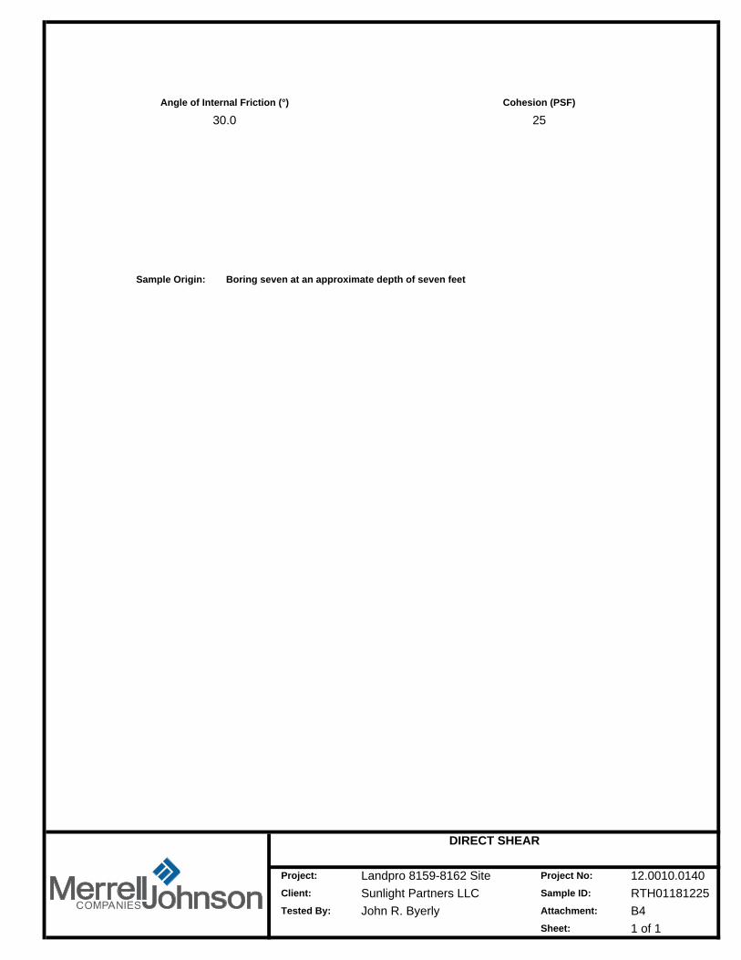
Angle of Internal Friction (°) Cohesion (PSF)
30.0 25
Sample Origin: Boring seven at an approximate depth of seven feet
Attachment:
Sheet:
DIRECT SHEAR
12.0010.0140RTH01181225B41 of 1

7
7 22.2
2.46
1.0
Initial Moisture Content (%)
Classification
Boring Number:
Depth (ft):
Specimen Diameter (in)
Specimen Thickness (in)
Final Moisture Content (%)
Initial Dry Density (pcf)
RTH01181225
Sheet:
Client:
Project:
Tested By:
Landpro 8159-8162 SiteSunlight Partners LLCJohn R. Byerly
CONSOLIDATION
12.0010.0140
B51 of 1
Project No:
Sample ID:
Attachment:

ATTACHMENT C
SITE REFERENCE

SITE
Client:
Project No:Project:
TOPOGRAPHIC PLOT Site Plan Excerpt
12.0010.0140NAC1
Sample ID:Sunlight Partners LLCLandpro 8159-8162 Site
Attachment:
1 of 1Sheet:

Sunlight Partners LLCAttachment:
Landpro 8159-8162 Site
SITE VICINITY MAP
12.0010.0140NASample ID:
Project No:
C2Client:
Project:
SITE
Sheet: 1 of 1

AERIAL VIEW
12.0010.0140NA
Project No:Project:
C3Sample ID:Client:
Landpro 8159-8162 Site
Attachment:
1 of 1Sheet:
Sunlight Partners LLC
SITE

Project No:Project:
APPROXIMATE EXCAVATIONS LOCATIONS PLOTSite Plan Excerpt
12.0010.0140NA
1 of 1Sheet:
Sunlight Partners LLCC4
Sample ID:Client:Landpro 8159-8162 Site
Attachment:
B-1
B-5
B-3
B-2
B-4
B-10
B-9
B-8B-7
B-6

B-1
Project:
Client:
ON SITE PHOTOGRAPHS
12.0010.0140NA
Attachment:
Project No:
Sunlight Partners LLCC5
Landpro 8159-8162 SiteSample ID:
B-2
1 of 5Sheet:

B-3
ON SITE PHOTOGRAPHS
12.0010.0140NA
Attachment:
Project No:
Sunlight Partners LLCC5
Landpro 8159-8162 SiteSample ID:
Project:
Client:
B-4
2 of 5Sheet:

B-5
ON SITE PHOTOGRAPHS
12.0010.0140NA
Attachment:
Project No:
Sunlight Partners LLCC5
Landpro 8159-8162 SiteSample ID:
Project:
Client:
B-6
3 of 5Sheet:

B-7
ON SITE PHOTOGRAPHS
12.0010.0140NA
Attachment:
Project No:
Sunlight Partners LLCC5
Landpro 8159-8162 SiteSample ID:
Project:
Client:
B-8
4 of 5Sheet:

B-9
ON SITE PHOTOGRAPHS
12.0010.0140NA
Attachment:
Project No:
Sunlight Partners LLCC5
Landpro 8159-8162 SiteSample ID:
Project:
Client:
B-10
5 of 5Sheet:

ASSESSOR'S PARCEL MAP
12.0010.0140NAC61 of 1Sheet:
Client:
Project No:
Sample ID:Landpro 8159-8162 SiteSunlight Partners LLC
Attachment:
Project:

ATTACHMENT D
DETAIL ILLUSTRATIONS

5' MIN.
36" MIN.
CUT-FILL LOT
COMPACTED FILL
MATERIAL APPROVED BY SOILS ENGINEER
REMOVE UNSUITABLE MATERIAL
OVEREXCAVATE AND RECOMPACT
MATERIAL APPROVED BY SOILS ENGINEER
COMPACTED FILL
OVEREXCAVATE AND RECOMPACT
CUT LOT
36" MIN.
5' MIN.
NATURAL GROUND
NATURAL GROUND
DEEPER OVEREXCAVATION AND RECOMPACTION SHALL BE PERFORMED IF DETERMINED NECESARY BY SOILS ENGINEER.
NOTE:
REMOVE UNSUITABLE MATERIAL
TRANSITION LOT DETAIL
12.0010.0140NAD1
Client:
Project No:
Sample ID:Landpro 8159-8162 Site
Attachment:
Project:
Sunlight Partners LLC
5' MIN.
36" MIN.
CUT-FILL LOT
COMPACTED FILL
MATERIAL APPROVED BY SOILS ENGINEER
REMOVE UNSUITABLE MATERIAL
OVEREXCAVATE AND RECOMPACT
MATERIAL APPROVED BY SOILS ENGINEER
COMPACTED FILL
OVEREXCAVATE AND RECOMPACT
CUT LOT
36" MIN.
5' MIN.
NATURAL GROUND
NATURAL GROUND
DEEPER OVEREXCAVATION AND RECOMPACTION SHALL BE PERFORMED IF DETERMINED NECESARY BY SOILS ENGINEER.
NOTE:
REMOVE UNSUITABLE MATERIAL
1 of 1Sheet:

BENCH4' MIN.
BENCH HEIGHT(VARIES)
LOWEST BENCH(KEY)
12' MIN.
REMOVE UNSUITABLE MATERIAL
COMPACTED FILL
PROJECTED PLANE (1 TO 1 MAX.FROM TOE OF SLOPE TO
APPROVED GROUND)
NTURAL GROUND
2% MIN2' MIN.KEY DEPTH COMPACTED FILL
BENCH4' MIN.
2% MIN
LOWEST BENCH(KEY)
12' MIN.
BENCH HEIGHT(VARIES)CUT FACE (TO BE
CONSTRUCTED PRIORTO FILL PLACEMENT)
2% MIN
LOWEST BENCH(KEY)
12' MIN.
BENCH4' MIN.
BENCH HEIGHT(VARIES)
COMPACTED FILL
OVERBUILD & TRIM BACK
FINSHED SURFACE
NATURAL GROUND
2' MIN.KEY DEPTH
REMOVE UNSUITABLE MATERIAL
FILL SLOPE
FILL-OVER-CUT SLOPE
CUT FACE (TO BECONSTRUCTED PRIORTO FILL PLACEMENT)
CUT-OVER-FILL SLOPE
NATURAL GROUND
LOWEST BENCH: DEPTH AND WIDTH SUBJECT TO FIELD CHANGE BASED ON SOILS ENGINEER'S INSEPCTION.SUBDRAINAGE: BACK DRAINS MAY BE REQUIRED AT THE DISCRETION OF THE SOILS ENGINEER.
NOTES:
NATURAL GROUND
REMOVE UNSUITABLE MATERIAL
Attachment:
Project:
Sunlight Partners LLC
BENCHING DETAIL
12.0010.0140NAD2
Client:
Project No:
Sample ID:Landpro 8159-8162 Site
BENCH4' MIN.
BENCH HEIGHT(VARIES)
LOWEST BENCH(KEY)
12' MIN.
REMOVE UNSUITABLE MATERIAL
COMPACTED FILL
PROJECTED PLANE (1 TO 1 MAX.FROM TOE OF SLOPE TO
APPROVED GROUND)
NTURAL GROUND
2% MIN2' MIN.KEY DEPTH COMPACTED FILL
BENCH4' MIN.
2% MIN
LOWEST BENCH(KEY)
12' MIN.
BENCH HEIGHT(VARIES)CUT FACE (TO BE
CONSTRUCTED PRIORTO FILL PLACEMENT)
2% MIN
LOWEST BENCH(KEY)
12' MIN.
BENCH4' MIN.
BENCH HEIGHT(VARIES)
COMPACTED FILL
OVERBUILD & TRIM BACK
FINSHED SURFACE
NATURAL GROUND
2' MIN.KEY DEPTH
REMOVE UNSUITABLE MATERIAL
FILL SLOPE
FILL-OVER-CUT SLOPE
CUT FACE (TO BECONSTRUCTED PRIORTO FILL PLACEMENT)
CUT-OVER-FILL SLOPE
NATURAL GROUND
LOWEST BENCH: DEPTH AND WIDTH SUBJECT TO FIELD CHANGE BASED ON SOILS ENGINEER'S INSEPCTION.SUBDRAINAGE: BACK DRAINS MAY BE REQUIRED AT THE DISCRETION OF THE SOILS ENGINEER.
NOTES:
NATURAL GROUND
REMOVE UNSUITABLE MATERIAL
1 of 1Sheet:

TOP OF SLOPE
B2
1 hTOE OF SLOPE
A
FACE OF FOOTING
FACE OF BUILDING
TOP OF SLOPE
0 - 10'
10' - 20'
20'+ 10'
h/2 MIN.
5' MIN.
SLOPE HEIGHT (h)(feet)
SETBACK (A)(feet)
h/2 MIN.10' - 30'
30'+ 15'
SETBACK (B)(feet)
TOE OF SLOPE
0 - 10'
SLOPE HEIGHT (h)(feet)
5' MIN.
Attachment:
Landpro 8159-8162 SiteSample ID:
Project:
BUILDING SETBACK DETAIL
12.0010.0140NASunlight Partners LLC
Project No:
Client:
D3
TOP OF SLOPE
B2
1 hTOE OF SLOPE
A
FACE OF FOOTING
FACE OF BUILDING
TOP OF SLOPE
0 - 10'
10' - 20'
20'+ 10'
h/2 MIN.
5' MIN.
SLOPE HEIGHT (h)(feet)
SETBACK (A)(feet)
h/2 MIN.10' - 30'
30'+ 15'
SETBACK (B)(feet)
TOE OF SLOPE
0 - 10'
SLOPE HEIGHT (h)(feet)
5' MIN.
Sheet: 1 of 1

ATTACHMENT E
GENERAL GRADING SPECIFICATIONS

Project 12.0010.0140 Exhibit: E Sheet 1
GENERAL GRADING SPECIFICATIONS
Grading of the subject site should be performed in accordance with the provisions of the Uniform Building Code and/or applicable ordinances. The following is presented for your assistance in establishing proper grading criteria:
1. GENERAL INTENT
These specifications present the general procedure and requirements for grading and earthwork as shown on the approved grading plans, including preparation of areas to be filled, placement of fill, installation of sub-drains, and excavations. The recommendations contained in this geotechnical report are a part of the earthwork and grading specifications and shall supersede the provisions contained hereinafter in the case of conflict. Evaluations performed by the consultant during the course of grading may result in new recommendations, which could supersede these specifications, or the recommendations of this geotechnical report.
2. CONSTRUCTION INSPECTION
A representative of this firm should inspect all grading operations, including site clearing and stripping. The presence of our field representative will be for the purpose of providing observation and field testing, and will not include any supervising or directing of the actual work of the Contractor, his employees or agents. Neither the presence of our field representative nor the observations and testing by our firm shall excuse the Contractor in any way for defects discovered in this work. It is understood that our firm will not be responsible for job or site safety on this project, which will be the sole responsibility of the Contractor.
3. EARTHWORK OBSERVATION & TESTING
Prior to the commencement of grading, a representative of this firm or a qualified geotechnical consultant (soils engineer, engineering geologist, or their representatives) shall be employed for the purpose of observing earthwork procedures and testing the fills for conformance with recommendations of the geotechnical report and these specifications. It will be necessary that the consultant provide adequate testing and observation so that they may determine that the work was accomplished as specified. It shall be the responsibility of the contractor to assist the consultant and keep the consultant apprised of work schedules and changes so that the consultant may schedule personnel accordingly.

Project 12.0010.0140 Exhibit: E Sheet 2
It shall be the sole responsibility of the contractor to provide adequate equipment and methods to accomplish the work in accordance with applicable grading codes and/or agency ordinances, these specifications and the approved grading plans. If, in the opinion of the consultant, unsatisfactory conditions, such as questionable soils, poor moisture condition, inadequate compaction, adverse weather, etc. are resulting in a quality of work less than required in these specifications, the consultant will be empowered to reject the work and recommend that construction be stopped until the conditions are rectified.
4. FILL PLACEMENT AND COMPACTION
4.1. Fill Lifts
Approved fill material shall be placed in areas prepared to receive fill in near-horizontal layers not exceeding eight (8) inches in compacted thickness. The consultant may approve thicker lifts if testing indicates the grading procedures are such that adequate compaction is being achieved with lifts of greater thickness. Each layer shall be spread evenly and shall be thoroughly mixed during spreading to attain uniformity of material and moisture in each layer.
Fill must be inorganic, granular sands or gravel, free from rocks, or lumps greater than six (6) inches in maximum dimension. Each fill lift should be brought to near optimum moisture content and compacted to at least 95 percent (ASTM D1557, D1556, D2922). 4.2. Fill Moisture
Fill layers at a moisture content no less or more than +/- 2 % of optimum shall be watered and mixed, and over saturated / wet fill layers shall be aerated by scarification or shall be blended with drier material to obtain a moisture content of +/- 2% of the optimum moisture. Moisture-conditioning and mixing of fill layers shall continue until the fill material is at uniform moisture content at or near optimum moisture but within +/- 2% of the optimum moisture.
4.3. Compaction of Fill After each layer has been evenly spread, moisture conditioned, and mixed, it shall be uniformly compacted to not less than 95 percent of the maximum dry density (ASTM D1557). Compaction equipment shall be adequately sized and shall be either specifically designed for soil compaction or have proven reliability, to efficiently achieve the specified degree of compaction. In general, the compaction criteria specified below shall be followed unless otherwise noted.

Project 12.0010.0140 Exhibit: E Sheet 3
• Footing Subgrade 95% or Greater at +/- 2% Optimum Moisture • Concrete Slab Subgrade 95% or Greater at +/- 2% Optimum Moisture • Aggregate Base for Paved Areas 95% or Greater at +/- 2% Optimum Moisture • Upper 1’ of Subgrade, Paved Areas 95% or Greater at +/- 2% Optimum Moisture • Matt Foundation Subgrade 95% or Greater at +/- 2% Optimum Moisture • Cross Gutter Subgrade 95% or Greater at +/- 2% Optimum Moisture • Structural Fill 90% or Greater at +/- 2% Optimum Moisture • Curb and Gutter Subgrade 90% or Greater at +/- 2% Optimum Moisture • Sidewalk Subgrade 90% or Greater at +/- 2% Optimum Moisture • Retaining Wall Backfill 90% or Greater at +/- 2% Optimum Moisture • Trench Backfill 90% or Greater at +/- 2% Optimum Moisture
5. FILL SLOPES AND SLOPE CONSTRUCTION Permanent cut or fill slopes should be constructed with no slopes steeper than 2 horizontal to 1 vertical.
Compacting of slopes shall be accomplished by one of the following procedures:
• By bankrolling of slopes with sheep foot roller at frequent increments of 1 to 2 feet in fill
elevation gain, or by other methods producing satisfactory results.
• Fill slopes should be overfilled during construction and then cut back to expose fully compacted soil. The relative compaction of the slopes on to the slope face shall be at least 90 percent.
Where fills slopes are to be placed on existing slopes the ground should be benched. Any fills placed on slopes shall be benched and keyed per details of this report
If the fill is properly compacted, fill embankments may constructed at 2:1 (horizontal to vertical) of flatter. Fill slopes should be overfilled and trimmed back to the desired grade to provide a firm surface. All slopes should be provided with adequate drainage and should be planted immediately with erosion-resistant vegetation.
6. BENCHING
The existing surface shall be benched at least 12 feet wide at the lowest bench and shall be at least 2 feet deep into firm materials compacted to 90%. The lowest bench should be tilted in

Project 12.0010.0140 Exhibit: E Sheet 4
the slope at a 2% slope into the embankment. Other benches should be excavated into firm material for a minimum width of 4 feet, and all benches should be approximately 2 feet in height. Deeper removal and re-compaction may be required.
The existing slopes shall be benched to key the fill material to the underlying ground. A minimum of 2 feet normal to the slope shall be removed and re-compacted, as the fill is brought up in layers, to ensure that the new work is constructed on a firm foundation fill. Benching may vary based on field conditions and will be verified/confirmed by our field representative.
In no case will horizontal benching be less than 4 feet and vertical lifts more than 2 feet.
7. COMPACTION TESTING
Field-tests to check the fill moisture and degree of compaction will be performed by the consultant. The location and frequency of tests shall be at the consultant's discretion. In general, the tests will be taken at an interval not exceeding two feet in vertical rise and/or 1,000 cubic yards of embankment. Compaction testing will be in performed in accordance with the American Society for Testing and Materials Standards (ASTM), test methods ASTM D1556 and/or D2922 or other applicable standards.
Maximum dry density tests used to determine the degree of compaction will be performed in accordance with the American Society for Testing and Materials Standards (ASTM), test method ASTM D1557.
8. EXCAVATION
Excavations and cut slopes will be examined during grading. If directed by the consultant, further excavation or over excavation and refilling of cut areas shall be performed, and/or remedial grading of cut slopes shall be performed. Where fill-over-cut slopes are to be graded, unless otherwise approved, the cut portion of the slope shall be made and approved by the consultant prior to placement of materials for construction of the fill portion of the slope.
9. TRENCH BACKFILL
Trench excavations for utility pipes shall be backfilled under engineering supervision. After the utility pipe has been laid, the space under and around the pipe shall be backfilled with clean

Project 12.0010.0140 Exhibit: E Sheet 5
sand or approved granular soil to a depth of at least one foot over the top of the pipe. The sand backfill shall be uniformly jetted into place before the controlled backfill is placed over the sand. The on-site materials, or other soils approved by the consultant, shall be watered and mixed as necessary prior to placement in lifts over the sand backfill. The controlled backfill shall be compacted to at least 95 percent of the maximum laboratory density as determined by the ASTM compaction method described above.
Field density tests and inspection of the backfill procedures shall be made by the consultant during backfilling to see that proper moisture content and uniform compaction is being maintained. The contractor shall provide test holes and exploratory pits as required by the consultant to enable sampling and testing.

ATTACHMENT F
IMPORTANT INFORMATION ABOUT YOUR
GEOTECHNICAL ENGINEERING REPORT
(ASFE PUBLICATION)


![IDTA National Conference 08.08.11 [Read-Only] 1 Bringing Systems Together to Promote Family Recovery: In-Depth Technical AssistanceDepth Technical Assistance (IDTA) The National Conference](https://static.fdocuments.in/doc/165x107/5acb9c507f8b9a27628b80ae/idta-national-conference-080811-read-only-1-bringing-systems-together-to-promote.jpg)