Landmine Detection Robot Using Radio Frequency …jairjp.com/JULY 2015/03 VIDYASAGAR-02.pdf · ·...
5
Journal of Academia and Industrial Research (JAIR) Volume 4, Issue 2 July 2015 51 ©Youth Education and Research Trust (YERT) jairjp.com Vidyasagar et al., 2015 ISSN: 2278-5213 Landmine Detection Robot Using Radio Frequency Communication K. Vidyasagar*, U. Nageswar Rao, K. Suresh and MD. Abdul Farooq Dept. of Electronics and Communication Engineering, Sai Spurthi Institute of Technology, B-Gangaram Sattupalli Khammam dist. T.S., India Vidyasagar818@ gmail.com*, [email protected], [email protected]; +91 9705077527 ______________________________________________________________________________________________ Abstract Anti-social elements in the global environment are challenging the society with their destructive activities. The development of science and technology is misused by the anti-social elements. In order to safeguard the human life from the miserable incidents, this study focused to develop a robot to detect the bomb and landmine at any earth surface. A surveillance camera is incorporated to capture the video information. The captured video information is transmitted to the remote control room continuously for further analysis. An AT 89S52 microcontroller is used to regulate the operations. Radio Frequency (RF) Technology is adopted to control the directions and movement of the robot remotely. IEEE 802.15.4 wireless communication is adopted to receive the video information at the control room. Keywords: Anti-social elements, landmine, robot, AT 89S52 microcontroller, radio frequency. Introduction Safe guard the police and military authorities from explosive material is a critical component. Su et al. (2011) described the mechanism of the developed landmine detection robot by adopting the RF communication technology and GPS to identify the orientation of the robot with coordinates. PIC 30F4011 microcontroller was used to regulate the control operations of the robot. Fukushima et al. (2008) described the humanitarian demining robot gryphon. Achkar and Owayjan (2012) considered the Mean, Median, Gaussian noise filtering techniques, K-Means algorithm for image segmentation and clustering the acquired image and back propagation neural networks for classification and recognition of the image. Zubair and Choudary (2010) proposed a Graphical user interface for plotting the landmines, Scanned presentation PID controller and camera. Manual, semi-auto mode and auto mode is incorporated for detecting the landmine. Image processing is also imparted for accurate position of the robot. Robledo and Mery (2009) focused on ground penetrating radar (GPS), Electromagnetic induction (EMI) and nuclear quardruple resonance (NQR). Support vector machines, sensor fusion, neural networks had been applied for data processing. Ghribi et al. (2013) considered two microcontrollers Atmega 32 and 128. Atmega 32 microcontroller was used for emergency stop position of the robot. Atmega 128 was used to regulate the movement of the robot and to interface the RF communication device. Parameswari et al. (2014) used At 89C52 microcontroller to regulate the operations of the robot. Zigbee communication technology was adopted to receive the signal from the transmitter. Flash magic software is also incorporated to receive the signals from the robot. Considering the above facts in view, the prime motive of this study was to detect explosives (destructive materials). The prime component of the study is driving the robot in all directions to sense the explosives. Communication is established between the explosive detection robot and the command signal issue unit. In this study we used RF technology to send the message to the observer. The model was developed to sense various kinds of materials and to acquire the video information for remote analysis. Materials and methods Proximity switch: Proximity switch is used as a sensor to detect the land mines and bomb related components (Fig. 1). A coil is used to generate the high frequency electromagnetic field. The closer the target causes to increase the current flow. The oscillations will stop. This change will be detected by the sensor and output the detection signal. The sensing distance is estimated as 30 mm. The resultant signal is interfaced to the microcontroller for further processing. The proximity sensor is tested with various metals. The signal levels were recorded to develop the soft logic in the microcontroller At 89S52. In the absence of the metal, the output voltage at the proximity sensor is recorded as 4.95 V. Wireless infrared camera: This camera is operated with 2.4 GHz frequency to transmit and receive the video information. Camera will capture the video information and transmit to the control room for analysis. This wireless camera is able to transmit the video information up to ‘91’ m. This study considered only 40 m to receive the video information from the robot (Fig. 2). RESEARCH ARTICLE
Transcript of Landmine Detection Robot Using Radio Frequency …jairjp.com/JULY 2015/03 VIDYASAGAR-02.pdf · ·...
Journal of Academia and Industrial Research (JAIR) Volume 4, Issue 2 July 2015 51
©Youth Education and Research Trust (YERT) jairjp.com Vidyasagar et al., 2015
ISSN: 2278-5213
Landmine Detection Robot Using Radio Frequency Communication
K. Vidyasagar*, U. Nageswar Rao, K. Suresh and MD. Abdul Farooq Dept. of Electronics and Communication Engineering, Sai Spurthi Institute of Technology,
B-Gangaram Sattupalli Khammam dist. T.S., India Vidyasagar818@ gmail.com*, [email protected], [email protected]; +91 9705077527
______________________________________________________________________________________________
Abstract Anti-social elements in the global environment are challenging the society with their destructive activities. The development of science and technology is misused by the anti-social elements. In order to safeguard the human life from the miserable incidents, this study focused to develop a robot to detect the bomb and landmine at any earth surface. A surveillance camera is incorporated to capture the video information. The captured video information is transmitted to the remote control room continuously for further analysis. An AT 89S52 microcontroller is used to regulate the operations. Radio Frequency (RF) Technology is adopted to control the directions and movement of the robot remotely. IEEE 802.15.4 wireless communication is adopted to receive the video information at the control room.
Keywords: Anti-social elements, landmine, robot, AT 89S52 microcontroller, radio frequency.
Introduction Safe guard the police and military authorities from explosive material is a critical component. Su et al. (2011) described the mechanism of the developed landmine detection robot by adopting the RF communication technology and GPS to identify the orientation of the robot with coordinates. PIC 30F4011 microcontroller was used to regulate the control operations of the robot. Fukushima et al. (2008) described the humanitarian demining robot gryphon. Achkar and Owayjan (2012) considered the Mean, Median, Gaussian noise filtering techniques, K-Means algorithm for image segmentation and clustering the acquired image and back propagation neural networks for classification and recognition of the image. Zubair and Choudary (2010) proposed a Graphical user interface for plotting the landmines, Scanned presentation PID controller and camera. Manual, semi-auto mode and auto mode is incorporated for detecting the landmine. Image processing is also imparted for accurate position of the robot. Robledo and Mery (2009) focused on ground penetrating radar (GPS), Electromagnetic induction (EMI) and nuclear quardruple resonance (NQR). Support vector machines, sensor fusion, neural networks had been applied for data processing. Ghribi et al. (2013) considered two microcontrollers Atmega 32 and 128. Atmega 32 microcontroller was used for emergency stop position of the robot. Atmega 128 was used to regulate the movement of the robot and to interface the RF communication device. Parameswari et al. (2014) used At 89C52 microcontroller to regulate the operations of the robot. Zigbee communication technology was adopted to receive the signal from the transmitter. Flash magic software is also incorporated to receive the signals from the robot.
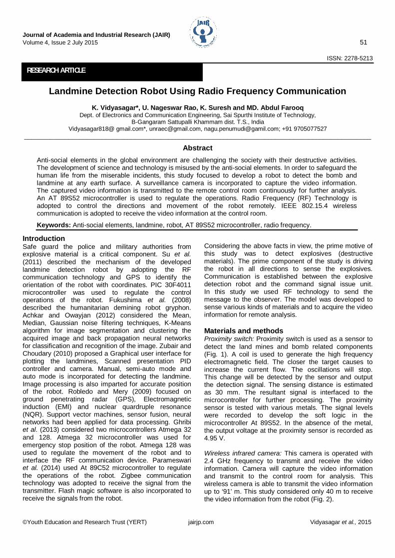
Considering the above facts in view, the prime motive of this study was to detect explosives (destructive materials). The prime component of the study is driving the robot in all directions to sense the explosives. Communication is established between the explosive detection robot and the command signal issue unit. In this study we used RF technology to send the message to the observer. The model was developed to sense various kinds of materials and to acquire the video information for remote analysis. Materials and methods Proximity switch: Proximity switch is used as a sensor to detect the land mines and bomb related components (Fig. 1). A coil is used to generate the high frequency electromagnetic field. The closer the target causes to increase the current flow. The oscillations will stop. This change will be detected by the sensor and output the detection signal. The sensing distance is estimated as 30 mm. The resultant signal is interfaced to the microcontroller for further processing. The proximity sensor is tested with various metals. The signal levels were recorded to develop the soft logic in the microcontroller At 89S52. In the absence of the metal, the output voltage at the proximity sensor is recorded as 4.95 V. Wireless infrared camera: This camera is operated with 2.4 GHz frequency to transmit and receive the video information. Camera will capture the video information and transmit to the control room for analysis. This wireless camera is able to transmit the video information up to ‘91’ m. This study considered only 40 m to receive the video information from the robot (Fig. 2).
RESEARCH ARTICLE
Journal of Academia and Industrial Research (JAIR) Volume 4, Issue 2 July 2015 52
©Youth Education and Research Trust (YERT) jairjp.com Vidyasagar et al., 2015
Fig. 1. Proximity switch.
Fig. 2. Wireless infrared camera.
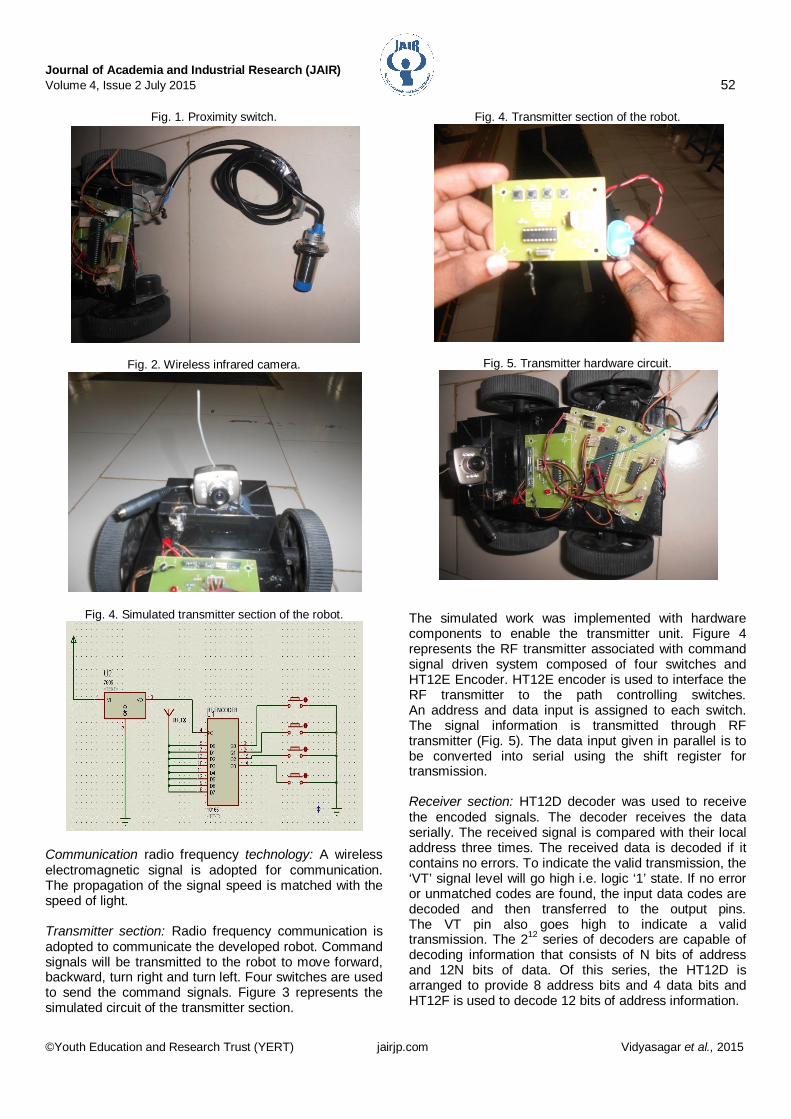
Fig. 4. Simulated transmitter section of the robot.
Communication radio frequency technology: A wireless electromagnetic signal is adopted for communication. The propagation of the signal speed is matched with the speed of light. Transmitter section: Radio frequency communication is adopted to communicate the developed robot. Command signals will be transmitted to the robot to move forward, backward, turn right and turn left. Four switches are used to send the command signals. Figure 3 represents the simulated circuit of the transmitter section.
Fig. 4. Transmitter section of the robot.
Fig. 5. Transmitter hardware circuit.
The simulated work was implemented with hardware components to enable the transmitter unit. Figure 4 represents the RF transmitter associated with command signal driven system composed of four switches and HT12E Encoder. HT12E encoder is used to interface the RF transmitter to the path controlling switches. An address and data input is assigned to each switch. The signal information is transmitted through RF transmitter (Fig. 5). The data input given in parallel is to be converted into serial using the shift register for transmission. Receiver section: HT12D decoder was used to receive the encoded signals. The decoder receives the data serially. The received signal is compared with their local address three times. The received data is decoded if it contains no errors. To indicate the valid transmission, the ‘VT’ signal level will go high i.e. logic ‘1’ state. If no error or unmatched codes are found, the input data codes are decoded and then transferred to the output pins. The VT pin also goes high to indicate a valid transmission. The 212 series of decoders are capable of decoding information that consists of N bits of address and 12N bits of data. Of this series, the HT12D is arranged to provide 8 address bits and 4 data bits and HT12F is used to decode 12 bits of address information.
Journal of Academia and Industrial Research (JAIR) Volume 4, Issue 2 July 2015 53
©Youth Education and Research Trust (YERT) jairjp.com Vidyasagar et al., 2015
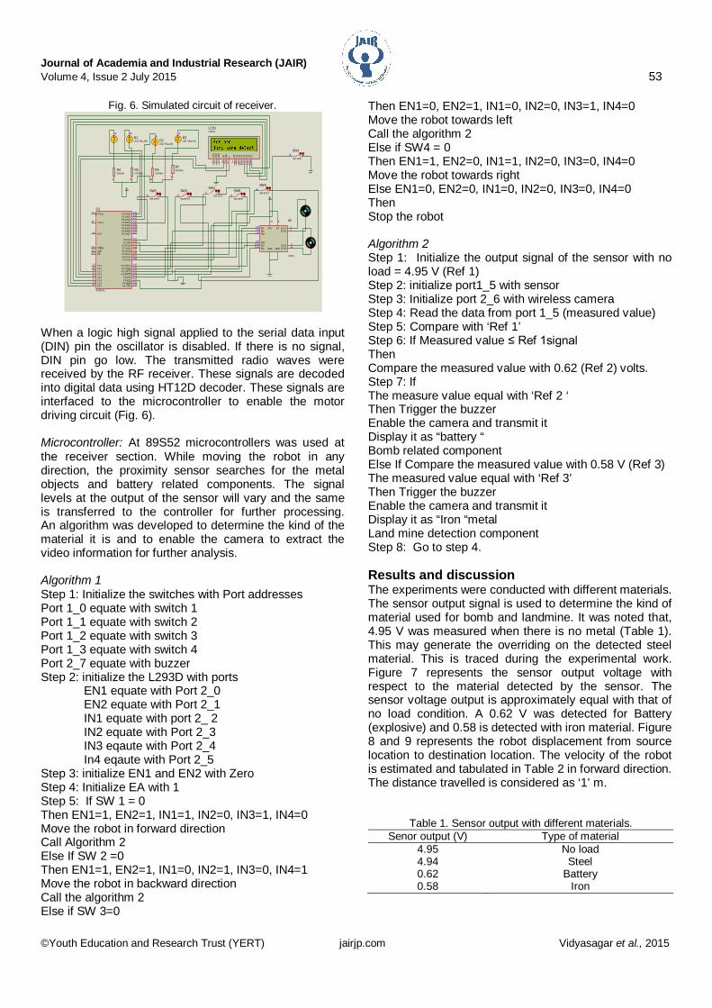
Fig. 6. Simulated circuit of receiver.
When a logic high signal applied to the serial data input (DIN) pin the oscillator is disabled. If there is no signal, DIN pin go low. The transmitted radio waves were received by the RF receiver. These signals are decoded into digital data using HT12D decoder. These signals are interfaced to the microcontroller to enable the motor driving circuit (Fig. 6). Microcontroller: At 89S52 microcontrollers was used at the receiver section. While moving the robot in any direction, the proximity sensor searches for the metal objects and battery related components. The signal levels at the output of the sensor will vary and the same is transferred to the controller for further processing. An algorithm was developed to determine the kind of the material it is and to enable the camera to extract the video information for further analysis. Algorithm 1 Step 1: Initialize the switches with Port addresses Port 1_0 equate with switch 1 Port 1_1 equate with switch 2 Port 1_2 equate with switch 3 Port 1_3 equate with switch 4 Port 2_7 equate with buzzer Step 2: initialize the L293D with ports EN1 equate with Port 2_0 EN2 equate with Port 2_1 IN1 equate with port 2_ 2 IN2 equate with Port 2_3 IN3 eqaute with Port 2_4 In4 eqaute with Port 2_5 Step 3: initialize EN1 and EN2 with Zero Step 4: Initialize EA with 1 Step 5: If SW 1 = 0 Then EN1=1, EN2=1, IN1=1, IN2=0, IN3=1, IN4=0 Move the robot in forward direction Call Algorithm 2 Else If SW 2 =0 Then EN1=1, EN2=1, IN1=0, IN2=1, IN3=0, IN4=1 Move the robot in backward direction Call the algorithm 2 Else if SW 3=0
Then EN1=0, EN2=1, IN1=0, IN2=0, IN3=1, IN4=0 Move the robot towards left Call the algorithm 2 Else if SW4 = 0 Then EN1=1, EN2=0, IN1=1, IN2=0, IN3=0, IN4=0 Move the robot towards right Else EN1=0, EN2=0, IN1=0, IN2=0, IN3=0, IN4=0 Then Stop the robot Algorithm 2 Step 1: Initialize the output signal of the sensor with no load = 4.95 V (Ref 1) Step 2: initialize port1_5 with sensor Step 3: Initialize port 2_6 with wireless camera Step 4: Read the data from port 1_5 (measured value) Step 5: Compare with ‘Ref 1’ Step 6: If Measured value ≤ Ref 1signal Then Compare the measured value with 0.62 (Ref 2) volts. Step 7: If The measure value equal with ‘Ref 2 ‘ Then Trigger the buzzer Enable the camera and transmit it Display it as “battery “ Bomb related component Else If Compare the measured value with 0.58 V (Ref 3) The measured value equal with ‘Ref 3’ Then Trigger the buzzer Enable the camera and transmit it Display it as “Iron “metal Land mine detection component Step 8: Go to step 4. Results and discussion The experiments were conducted with different materials. The sensor output signal is used to determine the kind of material used for bomb and landmine. It was noted that, 4.95 V was measured when there is no metal (Table 1). This may generate the overriding on the detected steel material. This is traced during the experimental work. Figure 7 represents the sensor output voltage with respect to the material detected by the sensor. The sensor voltage output is approximately equal with that of no load condition. A 0.62 V was detected for Battery (explosive) and 0.58 is detected with iron material. Figure 8 and 9 represents the robot displacement from source location to destination location. The velocity of the robot is estimated and tabulated in Table 2 in forward direction. The distance travelled is considered as ‘1’ m.
Table 1. Sensor output with different materials. Senor output (V) Type of material
4.95 No load 4.94 Steel 0.62 Battery 0.58 Iron
X TAL218
X TAL119
A LE30
EA31
P SEN29
RST9
P0.0/AD0 39
P0.1/AD1 38
P0.2/AD2 37
P0.3/AD3 36
P0.4/AD4 35
P0.5/AD5 34
P0.6/AD6 33
P0.7/AD7 32
P 1.01
P 1.12
P 1.23
P 1.34
P 1.45
P 1.56
P 1.67
P 1.78
P3.0/RXD 10
P3.1/TXD 11
P3.2/ INT0 12
P3.3/ INT1 13
P 3.4/T0 14
P3.7/RD 17P3.6/WR 16P 3.5/T1 15
P2.7/A15 28
P2.0/A8 21
P2.1/A9 22
P2.2/A10 23
P2.3/A11 24
P2.4/A12 25
P2.5/A13 26
P2.6/A14 27
U1
AT89C51
IN12 OUT1 3
OUT2 6
OUT3 11
OUT4 14
IN27
IN310
IN415
EN11
EN29
VS
8
VSS
16
GND GND
U2
L293D
D7
14D
613
D5
12D
411
D3
10D
29
D1
8D
07
E6
RW5
RS4
VSS
1VD
D2
VEE
3
LCD1LM016L
SW2
SW-SPST
SW3
SW-SPST
SW4
SW-SPST
SW5
SW-SPST
SW6
SW-SPST
D1LED-YELLOW D2
LED-YELLOW
D3LED-YELLOW
R4330ohm
R5330Ohm
R6330Ohm
R7330Ohm
SW1
SW-SPST
Journal of Academia and Industrial Research (JAIR) Volume 4, Issue 2 July 2015 54
©Youth Education and Research Trust (YERT) jairjp.com Vidyasagar et al., 2015
Fig. 7. Sensor out signal vs material.
Fig. 8. Robot at source point.
Fig. 9. Robot reached to destination.
Fig.10. Video transmitted from camera to laptop.
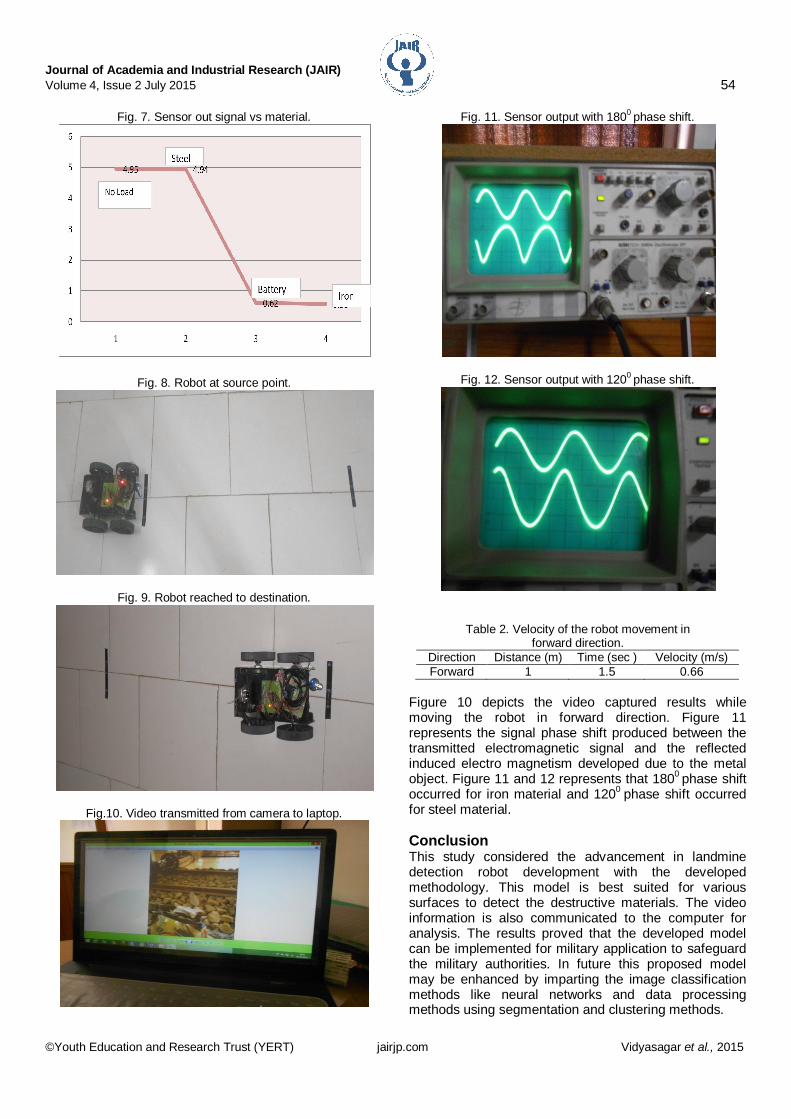
Fig. 11. Sensor output with 1800 phase shift.
Fig. 12. Sensor output with 1200 phase shift.
Table 2. Velocity of the robot movement in forward direction.
Direction Distance (m) Time (sec ) Velocity (m/s) Forward 1 1.5 0.66
Figure 10 depicts the video captured results while moving the robot in forward direction. Figure 11 represents the signal phase shift produced between the transmitted electromagnetic signal and the reflected induced electro magnetism developed due to the metal object. Figure 11 and 12 represents that 1800 phase shift occurred for iron material and 1200 phase shift occurred for steel material. Conclusion This study considered the advancement in landmine detection robot development with the developed methodology. This model is best suited for various surfaces to detect the destructive materials. The video information is also communicated to the computer for analysis. The results proved that the developed model can be implemented for military application to safeguard the military authorities. In future this proposed model may be enhanced by imparting the image classification methods like neural networks and data processing methods using segmentation and clustering methods.

Journal of Academia and Industrial Research (JAIR) Volume 4, Issue 2 July 2015 55
©Youth Education and Research Trust (YERT) jairjp.com Vidyasagar et al., 2015
Acknowledgements Authors would like to express their sincere thanks to the management and principal Dr. Ch. Vijaya kumar of Sai Spurthi Institute of Technology for providing the fund and necessary infrastructure. References 1. Achkar, R. and Owayjan, M. 2012. Implementation of a
vision system for a landmine detecting robot using artificial neural network. Int. J. Artificial Intellig. Appl. 3(5): 73-92.
2. Fukushima, E.F., Freese, M., Matsuzawa, T., Aibara, T. and Hirose, S. 2008. Humanitarian demining robot gryphon–current status and an objective evaluation. Int. J. Smart Sensing Intellig. Syst. 1(3): 735-753.
3. Ghribi, W., Badawy, A.S., Rahmathullah, M. and Changalasetty, S.B. 2013. Design and implementation of landmine robot. Int. J. Engg. Innov. Technol. 2(11): 250-256.
4. Parameswari, P., Pushpaveni, T., Kavya Dheeritha, K.,
Geethanjali, B. and Sujatha, E. 2014. Wireless networks based mine detection robot using embedded systems. Int. J. Engg. Sci. Technol. 3(6): 183-186.
5. Robledo, M. and Mery, C.D. 2009. A survey of land mine detection technology. Int. J. Remote Sensing. 30(9): 2399-2410.
6. Su, K.L., Su, H.S. and Shaio, S.W. 2011. Motion planning for a landmine-detection robot. Springer Artificial life Robotics. 16(3): 277-280.
7. Zubair, M. and Choudary, M.A. 2010. Landmine detecting robot capable of path planning, IEEE Explore Software Engineering (WCSE), 2010 Second World Congress. 1: 34-37.