LAND ROVER SIII_ROM_Part_4Fuel Cont Exhaust, Coolant and Clutch and Gearbox
49
FUEL LIFT PUMP, 214litre models Remove a nd refit 19.45.09 Removing 1 Remo ve b on net p an el. 7 6.16 .0 1 2 Re mo ve t h e air cl ea n er . 1 9.10 .0 4. 3 Di sc on n ec t f uel p ip es at fu el p ump . NOTE: The pump illust rated isfor 2v..l it re Pe tr ol mo de ls. Th e Di esel eng in e p ump is similar except that no filter bowl is re- quired. 4 Remove the fixings and withdraw the pump and si de cover complet e. S Remove the fuel pump from the side cover. Refitting 6 Refit pump to cover. 7 Smear general purpose grease on both s ides o f t he j oi nt washe r. 8 Refit the fuel pump and joint washer and c on ne ct t he fuel pi pe s. 9 Prime the fuel pump by operating the h an d pr i me le ver unti l no resi st ance is felt. 10 Diesel models. Release the air vent sc rews o n th e fu el d istr ib utor c asin g (19.50.01 refers) and operate the p ump h an d p rime le ve r unti l the fuel flow from the vent screws is free of air. Cl os e the vent screws. 11 R ev erse i nst ruct ions 1 and 2. 'D I N F UE L L IF T P UMP , 2. 6 litr e m ode ls Remove and ref it 19.45.09 FUEL LIFT PUMP, 21 4li tre models Overhaul 19.45.16 6 Ease the diaphragm from pump body, . slightly depress metal p~ of dia- ph ra gm and tum throug h 90 in eithe r dire ction wh ereon the diaphragm spring wi ll push di aphragm cl ear . 7 File the peening marks from the oil se al housing and l ev er o ut o il seal and retainer. 8 Using a small chisel, remove the stak- ing fr om the rocke r ar m retainers. 9 Wi th dr aw t he re ta in er s. 10 Withdra w the r oc ke r a nn . 11 Withdraw the rocker ann pin and washers. 12 De ta c h the opera tin g l i nk . 13 Withdr aw the rocker ar m spring. continued II 'R'1028 Removing 1 Di s co n ne ct t he b at te ry l ea ds. 2 Lift the seat (RH side) and remove the seat box panel to expose the fuel pump. 3 Disconnect the wiring at the snap connector. 4 Disconn ect the fue l ou tlet pip e. S Disconnect the fuel in le t p ip es. 6 Remov e the clamp fixing s. 7 Withdraw the pump and mounting rubbers. Refitting 8 Reve rse i nstruc tions 1to 7. Dismantling 1 Remove th e lift pump . 19. 45.0 9 2 2v. litre Petrol. Unscrew the nut at base of sediment bowl, move the retainer aside, and withdr aw the bowl , s ea li ng w ash er a nd fi lt er g au ze . Ca re should be taken to avoid damage to fil ter gauz e. 3 Mark the upper and lower halves of pump ca sing to ensure correc t a lign- ment on reas sembly. 4 Remove top cover fixing screws, and wh il e pr e ssin g di aph ra gm ta b aga in s t pump b od y, lif t top cove r cl ear. IRe 1024 S If required, remove the val vesretai ning st a ki ng using a scraper, warm the to p cov er and wi thd raw the valves. NOTE: Note the valves fitted position befo re removi ng.
-
Upload
flemmingrem -
Category
Documents
-
view
220 -
download
0
Transcript of LAND ROVER SIII_ROM_Part_4Fuel Cont Exhaust, Coolant and Clutch and Gearbox

8/3/2019 LAND ROVER SIII_ROM_Part_4Fuel Cont Exhaust, Coolant and Clutch and Gearbox
http://slidepdf.com/reader/full/land-rover-siiirompart4fuel-cont-exhaust-coolant-and-clutch-and-gearbox 1/50
FUEL LIFT PUMP, 214litre models
Remove and refit 19.45.09
Removing1 Remove bonnet panel. 76.16.012 Remove the air cleaner. 19.10.04.3 Disconnect fuel pipes at fuel pump.NOTE: The pump illustrated is for 2v..litrePetrol models. The Diesel engine pump is
similar except that no filter bowl is re-quired.4 Remove the fixings and withdraw the
pump and side cover complete.S Remove the fuel pump from the side
cover.
Refitting6 Refit pump to cover.7 Smear general purpose grease on both
sides of the joint washer.8 Refit the fuel pump and joint washer
and connect the fuel pipes.9 Prime the fuel pump by operating the
hand prime lever until no resistance isfelt.
10 Diesel models. Release the air vent
screws on the fuel distributor casing(19.50.01 refers) and operate thepump hand prime lever until the fuelflow from the vent screws is free ofair. Close the vent screws.
11 Reverse instructions 1 and 2.
'D
IN
FUEL LIFT PUMP, 2.6 litre models
Remove and refit 19.45.09
FUEL LIFT PUMP, 214litre models
Overhaul 19.45.16
6 Ease the diaphragm from pump body,. slightly depress metal p~ of dia-phragm and tum through 90 in eitherdirection, whereon the diaphragmspring will push diaphragm clear.
7 File the peening marks from the oilseal housing and lever out oil seal and
retainer.
8 Using a small chisel, remove the stak-
ing from the rocker arm retainers.9 Withdraw the retainers.10 Withdraw the rocker ann.11 Withdraw the rocker ann pin and
washers.12 Detach the operating link.13 Withdraw the rocker arm spring.
continued
II
'R'1028
Removing1 Disconnect the battery leads.2 Lift the seat (RH side) and remove the
seat box panel to expose the fuelpump.
3 Disconnect the wiring at the snap
connector.4 Disconnect the fuel outlet pipe.S Disconnect the fuel inlet pipes.6 Removethe clamp fixings.
7 Withdraw the pump and mountingrubbers.
Refitting8 Reverseinstructions 1to 7.
Dismantling1 Remove the lift pump. 19.45.092 2v.. litre Petrol. Unscrew the nut at
base of sediment bowl, move theretainer aside, and withdraw the bowl,sealing washer and filter gauze. Care
should be taken to avoid damage tofilter gauze.3 Mark the upper and lower halves of
pump casing to ensure correct align-ment on reassembly.
4 Remove top cover fixing screws, andwhile pressing diaphragm tab againstpump body, lift top cover clear.
IRe 1024
S Ifrequired, remove the valvesretainingstaking using a scraper, warm the topcover and withdraw the valves.
NOTE: Note the valves fitted positionbefore removing.

8/3/2019 LAND ROVER SIII_ROM_Part_4Fuel Cont Exhaust, Coolant and Clutch and Gearbox
http://slidepdf.com/reader/full/land-rover-siiirompart4fuel-cont-exhaust-coolant-and-clutch-and-gearbox 2/50
14 It is extremely unlikely that the handpriming mechanism will ever requirereplacement, but may be removed byfiling the hexagon each side of theoperating lever and springing the handlever clear, withdraw the cork washersand hand rocker.
Inspecting15 Clean all parts thoroughly in paraffin.
16 Examine all parts for wear and replaceas necessary.17 Replace all gaskets.18 Sediment bowl filter disc must be free
of damage and fit tightly around inletneck of upper casing. (2% Petrolmodels).
19 Renew diaphragm assemblyif any signof hardening, cracking or porosity ispresent.
20 Only very slight wear should be tole-rated at the rocker arm contact face,pivot pin, operating link and dia-phragm pull rod slots.
21 Springs should be replaced, ensurecorrect type are used.
22 Test valves for air tightness, by
suction.23 Check upper and lower casingflanges
for distortion, using a straight edge.
Reassembling24 Reverse 7 to 13. Re-stake to secure the
rocker lever retainers and the oil sealretainer.
25 To refit the diaphragm assembly, holdthe pump body with the diaphragmreturn spring in position, and therocker arm held outwards. Position thediaphragm over the spring with theflattened end of the pull rod in linewith the slot in the operating link.Push the diaphragm inwards and turnto lock.
26 Fit the valve gaskets into the top
cover.27 Fit the inlet and outlet valves andsecure by staking.
28 Place top cover assembly in position,aligning the marks made before dis-mantling. Fit securing screws, but donot tighten at this stage; using handpriming lever, fully depress diaphragmand fully tighten securing screws.
NOTE: The diaphragm outer edges shouldbe approximately flush with the outer edgeof the pump joint faces when fitted, anyappreciable protrusion of the diaphragmbeyond the joint face edges indicatesimproper fitment and necessitates therelease of the securing screws and refitmentin accordance with item 28.
29 2% litre Petrol. Replace filter gauzeand neoprene sealing ring, refit retain-ing clip and position sediment bowlcentrally and secure the retaining clip.
NOTE: Do not overtighten securing nut, toprevent cracking of sediment bowl.
Fuel pump test: without special equipment30 Immerse pump in a bath of paraffin
and operate rocker arm several timesto flush.
31 Hold the pump clear of the bath andcontinue to operate the rocker armunti l the pump is empty, then place afinger over the inlet port and operaterocker arm several times. A distinctsuction should be heard when thefinger is removed from the inlet port,denot ing that a reasonable degree ofsuction has been developed.
32 Place a finger over the outlet port andagain operate the rocker arm. Airpressure should be felt for two tothree seconds after rocker movementhas ceased. Build up the air pressure inthe pump again, and with the fingerheld firmly over the outlet, submergethe pump completely in the paraffinbath, then observe the joint face edgesfor signs of air leakage.
33 Fit the lift pump. 19.45.09.
FUEL LIFT PUMP 2.6 litre models
Overhaul 19.45.16
FUEL SYSTEM, 21.4 litre Dieselmodels
Priming 19.50.01
1 Remove the pump. 19.45.09.2 Release the end cap and withdraw the
gasket and filter.3 Renew the gasket and filter if neces-
sary.4 Reverse instructions I and 2
Procedure after dismantling filter/sedimentor, items 1 to 6.Procedure after emptying fuel system,items 7 to 12.Procedure after emptying distributor
pump, item 13.
Procedure after fuel mter/sedimentor dis-mantlingNOTE: When models fitted with a sedi-mentor have had the water drained onlyfrom the sedimentor bowl, no priming isnecessary as the water is replaced by fuelautomatically syphoned from the tank.However, if the sedimentor has been dis-mantled or air has entered the body, orwhere the fuel filter element has beenreplaced or the filter bowl cleaned, thenthe system must be primed asfollows:I Do not attempt to start the engine
hoping to draw the fuel through in thisway, otherwise the full priming pro-
cedure will be necessary..2 Slacken the bleed pipe banjo bolt on
the top of the main fuel filter.3 Operate the hand priming lever on the
mechanical pump, until fuel free frombubbles emerges.
NOTE: Alwaysensure that fuel pump leveris on the bottom of the operating camwhen priming the fuel system, otherwisemaximum moment of the priming leverwill not be obtained.4 Tighten the bleed pipe banjo bolt with
fuel still emerging.
j : , :#'"""~..,.

8/3/2019 LAND ROVER SIII_ROM_Part_4Fuel Cont Exhaust, Coolant and Clutch and Gearbox
http://slidepdf.com/reader/full/land-rover-siiirompart4fuel-cont-exhaust-coolant-and-clutch-and-gearbox 3/50
5 Operate the hand priming lever onceor twice to clear the last bubbles of airinto the filter bleed pipe.
6 Start engine in normal way and checkfor leaks.
Procedure when fuel system has beenemptied7 Carry out operations above, 1 to 5
inclusive.
8 Release air vent screw on dist ributorbody.
9 Operate the fuel pump hand priming
lever until fuel free of air emerges.10 Retighten the air vent screw.11 To ensure that all air is exhausted
from the pump it may also be neces-sary to slacken air vent screw in thedistributor control cover and repeatitems 9 and 10.
12 Start the enginein the normal way andcheck for leaks.
Procedure when distributor pump only hasbeen drained13 Carry out instructions 8 to 12 in-
clusive.
iNW
FUEL TANK DRAINING
WARNING: Petrol (gasoline) must not beextracted or drained from a vehicle stand-ing over a pit.Petroleum or gasoline vapour is highlyflammable, and in confined spaces is alsovery explosive and toxic.When petrol/gasoline evaporates it pro-duces IS O times its own volume in vapour,
which when diluted with air becomes anignitable mixture. The vapour is heavierthan air, and will always fall to the lowestlevel and it can readily be distributedthroughout a workshop by air currents.Even a small spillageof petrol or gasoline ispotentially very dangerous.Extracting or draining petrol (gasoline)from a vehicle fuel tank, must be carriedout in a well vent ilated area, preferablyoutside the workshop. All forms of ignitionmust be extinguished or removed, anyhand lamps must be flameproof and keptclear of any spillage. The receptacle used tocontain the petrol drained or extractedmust be more than adequate to receive thefull amount to be drained.
FUEL TANK, side mounted (asapplicable)
Remove and refit 19.55.01
RemovingI Disconnect the battery earth lead.2 Drain fuel into a clean container.3 Remove RH seat cushion and fold seat
squab forward.
4 Disconnect hoses, tank to filler tubeand breather hose.
5 Remove cover panel for fuel tank.6 Disconnect wires at gauge unit.7 Disconnect fuel supply pipe and for
Diesel models spill return pipes.8 Support tank and remove tank secur-
ing bolts.9 Lower tank and remove from under
the vehicle.
Refitting10 Reverse instructions 1to 9.II If the vehicle is a Diesel model, prime
the fuel system. 19.50.01.
FUEL TANK, rear mounted (asapplicable)
Remove and refit 19.55.01
Removing1 Disconnect the battery.2 Drain the fuel into a clean container.3 Release the clipsecuring the filler tube
hose to the tank.4 Support the tank and remove the tank
securing bolts, then lower the tanksufficient only to give access to thepipes and leads at the tank top.
5 Disconnect the breather and airbalance pipes.
6 Disconnect wires at gauge unit.7 Disconnect the fuel supply pipe, and
for Dieselmodels, the spillreturn pipe.8 Lower the tank and remove from
under the vehicle.
Refitting9 Reverse instructions 1to 8.10 If the vehicle is a Diesel model, prime
the fuel system. 19.50.01.

8/3/2019 LAND ROVER SIII_ROM_Part_4Fuel Cont Exhaust, Coolant and Clutch and Gearbox
http://slidepdf.com/reader/full/land-rover-siiirompart4fuel-cont-exhaust-coolant-and-clutch-and-gearbox 4/50
FUEL INJECTORS
Remove and refit 19.60.01
Removing1 Remove the bonnet panel. 76.16.01.2 Remove the a ir cleaner. 19.10.04.3 Slacken the injector feed pipes at the
distributor pump.4 Disconnect the injector feed pipes at
the injectors.
5 Disconnect the fuel spi ll pipes at No.4injector.
6 Slacken the spill rail fixings at theinjectors.
7 Remove the injector fixings.8 Withdraw the injectors complete with
spill rail.9 Take care to avoid damage to the
needle valves which protrude from theinjector faces. Immerse the com-ponents in clean fuel pending overhaulor refitting.
10 Remove the steel sealing washers fromthe injector housing bores.
11 The remaining sea ling washers (cop-per) are normally withdrawn with the
injectors, ensure that they are not lef tbehind in the bores.
Refitting12 Refit the new steel sealing washers
into the injector bores, with the raisedcorrugation uppermost.
13 Reverse 7 and 8, using new coppersealing washers. Injector fixings torque0,8 to 1,0 kgf. m (6 to 8 lbf. ft.).Tighten alternate fixings by equalamounts to ensure injec tor is sea tedsquarely.
14 Reverse 3 to 6.15 Prime the fuel system. 19.50.01.16 Reverse instruc tions 1and 2.
r
FUEL INJECTORS
Spray, check on vehicle
General
19.60.02
reconnect the pipe and nozz le assem-bly to the injection pump in a posit ionwhereby fuel ejection may beobserved.
4 Loosen the union nuts securing theremaining fuel pipes to injection noz-zles.
5 Whilst the starter turns the engineover, observe the manner in which fuelissues from the nozzle and comparethe spray form with the correct form
as illustrated.Very l itt le fuel should issue from themain spray hole wi th the engine turn-ing over at starter speed but a finespray comparable to tha t il lustratedshould be e jec ted from the auxi lia ryspray hole.
6 If the ejected fuel is more in the formof a liquid jet or issues from the mainpintle hole, then the nozzle and holderassembly should be removed for over-haul and a replacement unit f it ted.
7 Reverse instructions I to 4.
IRCI033
6
Injector nozzle type'Pintaux' nozzles are used, these being adevelopment of the 'Pintle' type nozzle.In a 'Pintle' nozzle, the valve s tem providesa pin or pintle which protrudes through the
nozzle body orifice to form the correctfuel spray angle.In a 'Pintaux' nozzle, an auxiliary sprayhole is also provided for easy starting.The 'Pintaux' type nozzle has beendeveloped by CAV for use with the type ofcylinder head chosen for Rover CI engines .This type of nozzle has been found mostsati sfac tory for starting and general run-ning and must be replaced by the sametype only.
Checking nozzle assembliesWARNING: Do not allow the fuel spray tocontact the person otherwise inj ury mayresult from skin penetration.
When an injec tion nozzle is considered tobe the cause of i rregular running and lossof power, a quick check may be made byloosening the fuel feed pipe union nut oneach nozzle in turn, whilst the engine isidling and again at approximately 1,000rev/min.If the injection nozzle assembly beingchecked has been operating properly, therewill be a dis tinct reduction in engine speedaccompanied by obvious roughness, but afaul ty injec tion nozzle may make li ttl e orno difference to the engine note when itsfuel feed pipe is loosened.
Checking spray1 Remove the fuel spill gallery pipe
complete from the injection nozzles .2 Disconnect the fuel feed pipe (injec-
tion pump to nozzle) from the nozz leto be tested and from the injectionpump.
:3 Release the fixings and withdraw thesuspected injection nozzle assembly;
f(-s. \.

8/3/2019 LAND ROVER SIII_ROM_Part_4Fuel Cont Exhaust, Coolant and Clutch and Gearbox
http://slidepdf.com/reader/full/land-rover-siiirompart4fuel-cont-exhaust-coolant-and-clutch-and-gearbox 5/50
FUEL INJECTORS
Overhaul 19.60.08
Dismantling and assembling, items 1 to 26.Benchtesting procedure, items 27 to 41.
Servicetools:271482 Spanner for nozzle cap271483 Injector nozzle testing and
setting kitTool for flushing injectornozzlesAdaptor for Pintaux injectorInjector nozzle cleaning kitInjector nozzle cleaning wire(0,2 mmdiameter)
278181
278182605002605003
NOTE: Where a number of tools aresupplied in kit form, the manufacturer'sidentification number is quoted in the textreferring to the specific tool.The individual tools which make up a kitare not available separately.
Dismantling1 Remove the injectors. 19.60.01.
2 Disconnect the injectors from the fuelspill rail.
3 Remove the combined locknut andend cap.
4 Withdraw the sealingwasher.
9
-.0
IN
V
8
5 Unscrew the pressure adjusting screw.6 Withdraw the pressure spring.7 Withdraw the valve spindle.8 Unscrewthe cap nut.9 Withdraw the nozzle valve and body.
Cleaningand inspecting10 Soak the component parts of the
assembly in Shell Calibration Fluid toloosen carbon deposits, but do notallow parts of anyone assembly to beinterchanged with those of another.
11 Brush away all external carbondeposits from component parts with abrass wire brush ET068 (or 7044/68)and replace them in the oil bath.Particular care must be exercised whencleaning the pintle and seat of nozzlevalve to avoid scratching or scoring,which may result in spray distortion.
12 Clean the three oil feed passagesin thenozzle body with a wire or drill of 1,5mm(0.062 in.) diameter.
13 Remove the carbon from the annularrecess with tool ET071 (or 7044/71).
14 Remove the carbon from the valveseat, using tool ET070 (or 7044/70)
with a rotary motion.15 Select the appropriate sizeprobe from
the pocket of cleaning kit and secure itin the pintle hole cleaner ET069 (or7044/69). Insert the probe into thebore of nozzle valve body and allowthe end to extend through the mainfuel outlet, then turn in a rotarymanner to remove carbon.
16 Carbon may be removed from thenozzle valve cone by inserting thevalve into tool ETOn (or 7044/72)and then rotating it alternately in aclockwise then anti-clockwise mannerwhilst pressing the valve inward. If thenozzle isblued or the seating has a dullcircumferential ring indicating pittingor wear, the nozzle body and valveshould be returned to a CAV ServiceAgentand replacement parts fitted.Do not attempt to lap the nozzlevalveto body. This process requires specialequipment and training.
I Re 1 03 5
m~?bI
14
IS
- e ? D ~ ~ > ~ ), , , e : 1036
16
~ ..}p
I Re 1 03 7
17 Clean the auxiliary spray hole usingtool ETl20 (or 7044/120) fitted withprobing wire 0,20 mm (0.008 in.)diameter. Wire605003.
NOTE: Allow 1,5 mm (0.062 in.) only toextend from the chuck and thus minimisethe possibility of the wire bending orbreaking while probing. Great care must betaken to prevent breakage of the wire inthe hole.
18 With flushing tool ET427 (or 278181)secured to the nozzle testing outfit, fitthe nozzle body (spray holes upper-most) to the flushing tool and pumptest oil through vigorously. This flush-ing process is necessary for theremoval of any tiny carbon particleswhich may have become lodged in thebody after scraping and probing.
19 Examine the pressure faces of nozzlebody and nozzle holder to ascertaintheir freedom from scoring andscratches. These surfaces must be per-fectly smooth.
continued
18
I R e 1 0 38
8/3/2019 LAND ROVER SIII_ROM_Part_4Fuel Cont Exhaust, Coolant and Clutch and Gearbox
http://slidepdf.com/reader/full/land-rover-siiirompart4fuel-cont-exhaust-coolant-and-clutch-and-gearbox 6/50
Reassembijng20 Fit the nozzle valve to nozzle and
check for freedom of movement.21 Immerse the nozzle body and valvein
the fluid bath and assemble whilstsubmerged.
22 Wash the rernammg componentsthoroughly and reverse dismantlingprocedure, items I to 8.
23 Set the inject ion nozzle assembly inaccordance with the following testprocedure.
Bench testing of injection nozzle andholder assembly
General information, items 24 to 2624 Tocheck a nozzle assembly and ensure
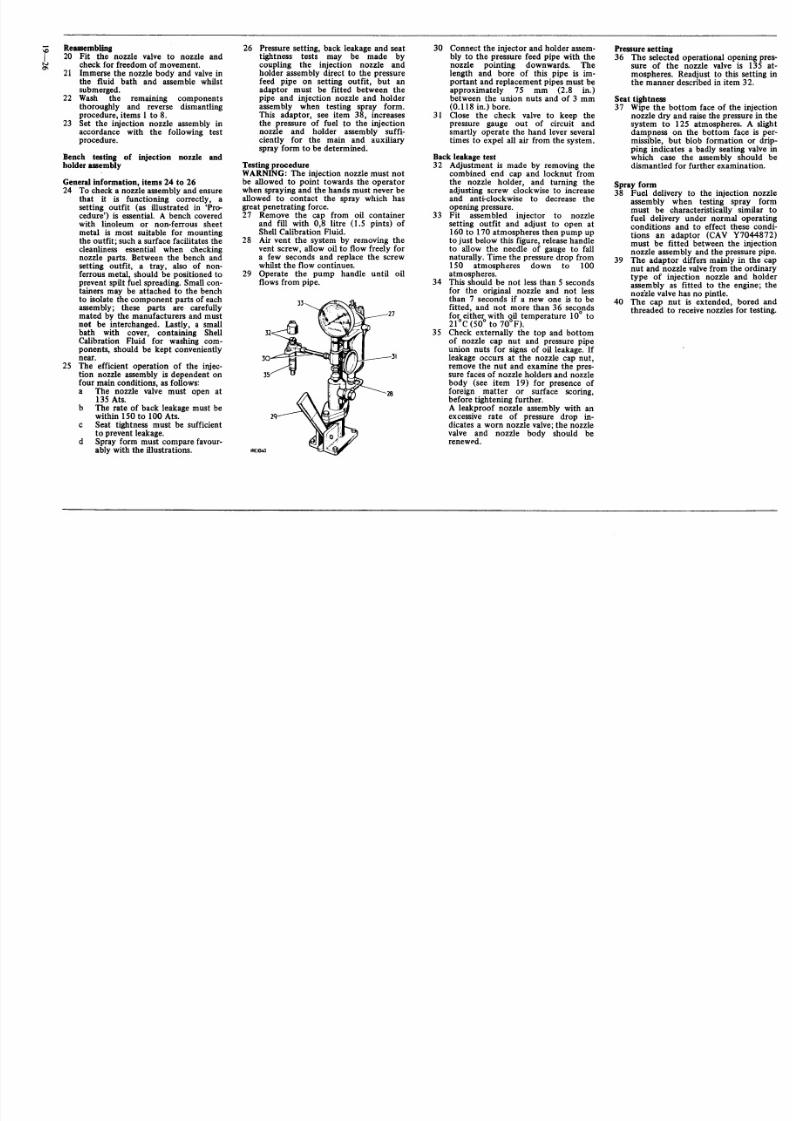
that it is functioning correctly, asetting outfit (as illustrated in 'Pro-cedure') is essential. A bench coveredwith linoleum or non-ferrous sheetmetal is most sui table for mountingthe outfit; such a surface facilitates thecleanliness essential when checkingnozzle parts. Between the bench andsetting outfit, a tray, also of non-
ferrous metal, should be positioned toprevent spilt fuel spreading. Smallcon-tainers may be attached to the benchto isolate the component parts of eachassembly; these parts are carefullymated by the manufacturers and mustnot be interchanged. Lastly, a smallbath with cover, containing ShellCalibration Fluid for washing com-ponents, should be kept convenientlynear.
25 The efficient operation of the injec-tion nozzle assembly is dependent onfour main conditions, as follows:a The nozzle valve must open at
135 Ats.b The rate of back leakage must be
within IS O to 100 Ats.c Seat tightness must be sufficient
to prevent leakage.d Spray form must compare favour-
ably with the illustrations.
26 Pressure setting, back leakage and seattightness tests may be made bycoupling the injection nozzle andholder assembly direct to the pressurefeed pipe on setting outfit, but anadaptor must be fitted between thepipe and injection nozzle and holderassembly when testing spray form.This adaptor, see item 38, increasesthe pressure of fuel to the injectionnozzle and holder assembly suffi-
ciently for the main and auxiliaryspray form to be determined.
TestingprocedureWARNING: The injection nozzle must notbe allowed to point towards the operatorwhen spraying and the hands must never beallowed to contact the spray which hasgreat penetrating force.27 Remove the cap from oil container
and fill with 0,8 litre (l.5 pints) ofShell Calibration Fluid.
28 Air vent the system by removing thevent screw, allow oil to flow freely fora few seconds and replace the screwwhilst the flow continues.
29 Operate the pump handle until oilflows from pipe.
30 Connect the injector and holder assem-bly to the pressure feed pipe with thenozzle pointing downwards. Thelength and bore of this pipe is im-portant and replacement pipes must beapproximately 75 mm (2.8 in.)between the union nuts and of 3 mm(0.ll8 in.) bore.
31 Close the check valve to keep thepressure gauge out of circuit andsmartly operate the hand lever severaltimes.to expel all air from the system.
Back leakage test32 Adjustment is made by removing the
combined end cap and locknut fromthe nozzle holder, and turning theadjusting screw clockwise to increaseand anti-clockwise to decrease theopening pressure.
33 Fit assembled injector to nozzlesetting outfit and adjust to open at160 to 170 atmospheres then pump upto just below this figure, release handleto allow the needle of gauge to fallnaturally. Time the pressure drop from150 atmospheres down to 100
atmospheres.34 This should be not less than 5 secondsfor the original nozzle and not lessthan 7 seconds if a new one is to befitted, and not more than 36 secondsfor either with oil temperature 10° to21°C (50° to 70°F).
35 Check external ly the top and bottomof nozzle cap nut and pressure pipeunion nuts for signs of oi l leakage. Ifleakage occurs at the nozzle cap nut ,remove the nut and examine the pres-sure faces of nozzle holders and nozzlebody (see item 19) for presence offoreign matter or surface scoring,before tightening further.A leakproof nozzle assembly with an
excessive rate of pressure drop in-dicates a worn nozzle valve;the nozzlevalve and nozzle body should berenewed.
Pressure setting36 The selected operational opening pres-
sure of the nozzle valve is 135 at-mospheres. Readjust to this setting inthe manner described in item 32.
Seat tightness37 Wipe the bottom face of the injection
nozzle dry and raise the pressure in thesystem to 125 atmospheres. A sl ightdampness on the bottom face is per-missible, but blob formation or drip-ping indicates a badly seating valve inwhich case the assembly should bedismantled for further examination.
Spray form38 Fuel delivery to the injection nozzle
assembly when testing spray formmust be characteristically similar tofuel delivery under normal operatingconditions and to effect these condi-tions an adaptor (CAY Y7044872)must be fit ted between the injectionnozzle assembly and the pressure pipe.
39 The adaptor differs mainly in the capnut and nozzle valvefrom the ordinary
type of injection nozzle and holderassembly as fitted to the engine; thenozzle valvehas no pintle.
40 The cap nut is extended, bored andthreaded to receive nozzles for testing.

8/3/2019 LAND ROVER SIII_ROM_Part_4Fuel Cont Exhaust, Coolant and Clutch and Gearbox
http://slidepdf.com/reader/full/land-rover-siiirompart4fuel-cont-exhaust-coolant-and-clutch-and-gearbox 7/50
41 Connect the adaptor assembly to thepressure pipe.
42 Remove the end cap and adjust theopening pressure of the nozzle valveto220 atmospheres.
43 Screw the injection nozzle and holderassembly to be tested, into the adap-tor.
44 With the check valve closed, operatethe handle smartly to expel air fromthe system. The auxiliary spray form
may be tested at 60 strokes per minuteand the main spray at 140. Spraydevelopment from starting to runningspeeds is illustrated, this illustrationshould be referred to and comparedwith the spray form of nozzles undertest.Spray formation should be well form-ed and free from splits or distortion. Aslight centre 'core' can be disregarded.Observe the main spray through 360
degreesto ensure a uniform spray.45 When satisfactory, reverse instructions
1 to 3.
rN. . . . . .
4RC 1267
Injector nozzle spray form, starting torunning conditions.
A
D
B ~c~ ~
F
4 RC 1 26 8
E

8/3/2019 LAND ROVER SIII_ROM_Part_4Fuel Cont Exhaust, Coolant and Clutch and Gearbox
http://slidepdf.com/reader/full/land-rover-siiirompart4fuel-cont-exhaust-coolant-and-clutch-and-gearbox 8/50

8/3/2019 LAND ROVER SIII_ROM_Part_4Fuel Cont Exhaust, Coolant and Clutch and Gearbox
http://slidepdf.com/reader/full/land-rover-siiirompart4fuel-cont-exhaust-coolant-and-clutch-and-gearbox 9/50
COOLANT
Drain and refill 26.10.01
Draining1 Remove the radti,A,t:erml~~p2 Remove
situated3· Open the
as follows:.
2 1 , 4 litre - at side adjacent to thedipstick. engines).2.6 litre hand side adjacent tothe enginebreather.
plug
Refilling4 Reverse 2 and 3. If antifreeze solution
is to be added, first pour 4.5 Iitres (8pints) of water into the system thenadd the required quantity of therecommended solution (see Section09).
5 Top up with water to between 12 mmand 19 mm (0.5 in. and 0.75 in.)below the bottom of the radiator f il lerneck.
6 Check and top up after the initial
short engine run.7 Ensure that the expansion tankcoolant is maintained at approxi-mately one-quarter full.
EXPANSION TANK
Remove and refit 26.15.01
Refitting8 Reverse 2 to7.Adjus t the fan belt tension
to6.3mm to 9.5 mm (0.25 in. toO.375 in.)checked by thumb pressure between thefan and crankshaft pulleys.
9 Refit the fan shroud.10 Close the bonnet.
FAN BLADES AND PULLEY - 2.6
LITRE MODELSRemove and refit 26.25.01
6 Withdraw the fan blades, packing pieceand pulley.
Refitting7 Reverse 3 to 6. Adjust the fan belt
tension to 8 mm to 11 mm (0.312 in.to 0.437 in.) checked by thumb pres-sure be tween the fan and crankshaftpulleys.
8 Refit the fan shroud.9 Close the bonnet. , ,
Where a viscous fan with p(~sti c blades isfitted:-
1 Remove the radiator - 26.40.04.2 Remove the four fixings to remove the
plastic fan.3 If necessary, remove the central ·nut
and washer to extract the~ouscoupling from the water pump/pulley.
Refitting4 Reverse 1 to 3.
Removing1 Open and prop the bonnet.2 Disconnec t the radiator overflow hose
at the expansion tank.3 Slacken the pinch bolt on the securing
bracket.
4 Withdraw the expansion tank.
Refitting5 Reverse 3 and 4.6 Refit the vent hose into the clips on
the tank retainer.7 Fi ll the expansion tank approximately
one-quarter full with coolant.8 Reconnect the overflow hose.9 Close the bonnet.
FAN BLADES AND PULLEY - 2%LITRE MODELS
Remove and refit 26.25.01RemovingI Open and prop the bonnet.2 Remove the shroud from the radia tor fan
cowl.3 Removethe cowlfixingsand holdthecowl
against the engine.4 Slacken the alternator f ixings5 Remove the fan belt.6 Removethe fan blade f ixings.7 Withdraw the fan bladesand pulley.
Removing1 Open and prop the bonnet.2 Where a steel bladed fan is fittedr-
remove the shroud from the radiatorfan cowl.
3 Slacken the alt ernator fixings.4 Remove the fan belt.5 Remove the fan blade fixings.

8/3/2019 LAND ROVER SIII_ROM_Part_4Fuel Cont Exhaust, Coolant and Clutch and Gearbox
http://slidepdf.com/reader/full/land-rover-siiirompart4fuel-cont-exhaust-coolant-and-clutch-and-gearbox 10/50
N
iN
RADIATOR AND FRONT PANELASSEMBLY
R e m ov e a nd r ef it 26.40.01
Removing1 Remove the bonnet.
2 Disconnect and remove the battery .3 Dra in the radia tor and cyl inder block.4 Remove five self-tapping screws and
remove the radiator gri lle.
5 Remove four screws and the front valance.6 Working from the wheel arch, remove the
fivenuts and bolts securing the front panelto the right-hand front wing. This willinclude the two nu ts and bolts retaining
the bonnet prop bracket .7 Slacken the th ird nut and bolt retaining
the bonnet prop bracket to facil itate align-ment of holes when refit ting.
8 Remove the five nuts securing the frontpanel to the le ft-hand wing and remove thestuds.
9 Release the top hose from the radiatorconnection.
10 Remove the nut securing the fan cowl tothe battery tray.
NOTE: Before car ry ing out ins truc tions I I and12make a note of the colour codes to fac il it at ere-connection.
II Release the head lamp and auxiliary har-ness from the 'P' clips fr om the centre o f
the front panel and disconnect the earthlead secured by the centre bol t.
12 Disconnec t the auxil ia ry harness f rom thelef t-hand s ide and wi thdraw the harnessfrom the right-hand side.
13 Disconnect the right-hand headlamp har-ness from the left-hand section at thecentre of th e r ad iato r apertur e and with-draw the cables through the grommets.
14 Remove the three nuts and bo lts secur ing
the fr ont panel to th e cr oss-member. Toensure correct alignment of the frontpanel on reassembly make a note of thenumber and posit ion of the rubber packingpieces.
15 Retr ieve the two bracket s for secur ing thefront valance.
16 Pul l the f ront panel and radia tor assembly
forward to enable the radiator bottomhose to be released from the water pumpconnection.
17 Withdraw the front panel and radiatorassembly complete.
18 Fit and tighten the radiator d rain p lug ( if
f it ted) or c lose the dra in top .
Refitting19 Lif t th e fr ont panel and radiator into po si-
tion and connect the bottom hose to thewater pump.
20 Refit the rubber packing pieces. in thesame positions as originally fitted toensure correct alignment of the radiator.
21 Fit the three nuts and bolts securing thef ront panel to the chass is c ross -member
and a tt ach the two brackets for ret ainingthe f ront valance to the two end bol ts .
22 Secure the front panel to the right-handwing and tighten the third nut and boltretaining the bonnet s tay bracket .
23 Fit the five nuts and bolts.
24 Fit the two strips of captive studs to theleft-hand side ofthe front panel and securewith the five nuts and washers .
25 Pass the left-hand and right-hand head-
l amp leads through the grommets and fas -ten together with the bullet connectors.
26 Pass the right-hand harness through theg rommets and connect to the lead s on theleft-hand side with bullet fas teners .
27 Secure the harness with the 'P'clips andconnect the ear th wire to the centre bol t inthe top of the f ront panel .
28 Connect the top hose to the radiator.29 Secure the fan cowl to the bat te ry t ray.30 Fit the fr ont valance.31 Fil l the cooling system in accordance with
instructions in operation 26.10.0 I.
32 Fit the bonnet.
RADIATOR
Remove and ref it 26.40.04
5 Remove the radiator grille.
6 Remove the radiator cap.7 Remove the radiator drain plug.8 Open the drain tap at the cylinder
block right hand side (2.6 litre) or lefthand s ide (2~ litre) models.
9 Disconnect the radiator top and
bottom hoses .10 Remove the fan cowl and shroud from
the radiator and displace rearwardsc lear of the radia tor.
Removing
I Open and support the bonnet.
2 Disconnect the battery earth lead.3 2.6 models - remove the air cleaner -
19.10.01.4 Remove the four screws and two
an ti-r attle clips secur ing the radiatorgrille.

8/3/2019 LAND ROVER SIII_ROM_Part_4Fuel Cont Exhaust, Coolant and Clutch and Gearbox
http://slidepdf.com/reader/full/land-rover-siiirompart4fuel-cont-exhaust-coolant-and-clutch-and-gearbox 11/50
11 Removethe expansion tank.12 Remove the fixings, radiator to grille
panel.
13 Carefully lift out the radiator avoidingthe fan bladesand shroud.
12 II
~~~~~~~"~'~~~~~~r~ ""
14 Where required, lift out the fan cowl.
Refitting15 Reverse1 to 14.16 Run the engine and check all hose
connections for leakages.
THERMOSTAT - 214 LITREMODELS
Removeand refit 26.45.01
Removing1 Remove the radiator cap and partially
drain the coolant.2 Remove the outlet pipe and thermo-
stat housing fixings.3 Withdraw the pipe and housing com-
plete.
4 Separate the pipe from the housingand withdraw the thermostat and '0'ringseal.
5 Withdraw and discard the jointwashers.
Refitting6 Smear- both sides of the new joint
washers with a small quantity ofgeneral purpose grease.
7 Ensure that the thermostat bleed holeis clear to prevent air locks whenrefilling.
8 Reverse 1 to 5.
THERMOSTAT - 2.6 LITREMODELS
Remove and refit 26.45.01
Removing
1 Drain off coolant at the engine suf-ficient to drain the thermostathousing.
2 Remove the fixings and lift aside theoutlet pipe.3 Withdraw the joint washer.4 Withdraw the thermostat.
Refitting5 Smear both sides of the new joint
washer with a small quantity ofgeneral purpose grease.
6 Ensure that the thermostat bleed holeis clear to prevent air locks whenrefilling.
7 Reverse 1 to 4.
THERMOSTAT
Test 26.45.09
Testing
1 Remove the thermostat. 26.45.01.2 Immerse the thermostat in water in a
suitable container.3 Heat the water and note the tempera-
ture at which the thermostat com-
mences to open; this should be withinthe range as follows:2I,4lit re engines - 70.5°C to 75.5°C.
2.6 litre engines - 75°C to 80°C.4 The thermostat is not adjustable or
serviceable; repair is by replacement.5 Reverse 1.
WATER PUMP - 214 LITREMODELS
Remove and refit 26.50.01
tltemoving
.- Removethe bonnet. 76.16.01.2 Drain the cooling system. 26.10.01.3 Remove the shroud from the radiator
fan cowl.4 Slacken the alternator fixings and
remove the fan belt.5 Remove the alternator adjusting link.6 Remove the fan blades.7 Withdraw the fan pulley.
8 Disconnect the radiator bottom hoseat the water pump.
9 Disconnect the by-pass hose.10 Remove the water pump.11 Withdraw the joint washer.
Refitting12 Smear both sides of a newjoint washer
with general purpose grease.13 Reverse 4 to 11.Adjust the fan belt to
give 6.3 to 9.5 mm (0.25 to 0.375 in.)
free movement when checked midway
between the fan and crankshaftpulleys.
14 Reverse 1 to 3.
WATER PUMP - 2.6 LITREMODELS
Remove and refit 26.50.01
Removing1 Remove the bonnet. 76.16.01.
2 Drain the cooling system. 26.10.01.3 Where a viscous fan with plastic fan
blades is fitted, remove the radiator,26.40.04., before removing the fanbelt, fan blades and pulley/viscouscoupling. 26.25.01.
4 Disconnect the radiator bottom hosefrom the water pump.
continued
8/3/2019 LAND ROVER SIII_ROM_Part_4Fuel Cont Exhaust, Coolant and Clutch and Gearbox
http://slidepdf.com/reader/full/land-rover-siiirompart4fuel-cont-exhaust-coolant-and-clutch-and-gearbox 12/50
. .
Nr 5 Where a heater is fitted, remove thewater valve. 80.10.16.
6 Remove the water pump fixings; notethe fitted positions of the varyinglength bolts.
7 Withdraw the water pump, tilt ing up-wards to clear the locating dowels andcompress the '0' ring seal on theby-pass outlet.
8 Withdraw the joint washer from the
adaptor joint face.
Refitting ,9 Smear both sides of. the new' joint
washer with a minimum of generalpurpose grease. . ,
10 Position the joint washer onto thepump adaptor face.
11 Lubricate a new '0' ring seal withSilicone Compound MS4 and positionthe sealon the pump by-pass outlet.
. .2 Reverse 7. Ensure that the '0' ringdoes not become dislodged.
13 Reverse 1to 6.
WATE R P UMP
Overhaul 26.Sb.O~
Dismantling1 Remove the water pump. 26.50.01.2 Remove the bearing location bolt.3 Drift out the impeller, bearing and
spindle as an assembly from the pumpbody and hub.
4 Cut through and remove .the sealassembly from the spindle.
5 Insert the spindle into the water pumpbody, so that the impeller is in theposition of the fan pulley.
6 Drift the spindle and bearing assemblyfrom the impeller.
Inspecting7 Examine the spindle and bearing
assembly; it need not be renewed ifthe bearing is satisfactory and thespindle is free from excessive cor-rosion.Clean any corroded portion of thespindle and paint with a suitable chlo-rinated rubber primer or, alternatively,with a good quality aluminium paint'or other anti-corrosive paint.
~ The impeller must be a press fit on thespindle. If the impeller isloose on thespindle, replace either part as neces-sary.
Re-assembling8 Wherea steel deflector washeris.iitted
to the pump spindle, check th;"a.'!thereis a minimum clearance of O : 4 l i mm(0.018 in.) between .the washer andthe bearing housing face.
-,- 8
IRe10K)
9 Insert a few drops of thick oil in thelocation hole in the bearing.
10 Suitably mark the spindle bearinghousing and the pump body so thatthe bearing locating screw holes maybe easily aligned during assembly.
11 Fit the spindle and bearing (0 the
pump body and fit the locating screw.
DATA
Dimension from front face of hub to rear(mounting) face of water pump2% litre models : .
2.6 litre models .
Clearance between impeller vanes andpumpbody .
Dimension from fan belt groove in pulleyto rear (mounting) face of water pump2%litre models ' ' .
2.6 litre models .
3
12 Press the fan pulley hub on to thespindle to a set dimension measuredbetween the front face of the pulleyhub and., t he mounting face of thewater pump body asfollows:2% litre models - 89,48 mm ± 0,25mm (3.523 in. ± 0.010 in.).2.6 litre models - 97,00 mm ± 0,25mm (3.819 in. ± 0.010 in.).When pressing on the hub, support thespindle to avoid load falling on the
bearing location bolt.13 Fit the carbon ring and seal assemblyto the pump body with the carbonring outwards.
14 Press the impeller onto the spindleuntil there is 0,50 mm to 0,63 mm(0.020 in. to 0.025 in.) clearancebetween the impeller vanes and thepump body. Check using feeler gauges.
15 Offer the fan pulley to the assemblyand check the fan belt groovepositionrelative to the pump mounting facewhich must be as follows>2%litre models - 49,4 mm ± 0,25 mm(1.945 in. ± 0.010 in.).2.6 litre models - 46,2 mm-c 0,25mm (1.819 in. ± 0.010 in.).
. 16 Reverse 1.
\
89,48 mm ± 0,25 mm(3.523 in. ±<l.010 in.)97,00 mm ± 0,25 mm(3.819 in. ± 0.010 in.)
0,50 mm to 0,63 mm (0.020 in.to 0.025 in.)
49,4 mm ± 0,25 mm(1.945 in. ± 0.010 in.)
46,2 mm ± 0,25mm(1.819 in. ± 0.010 in.)

8/3/2019 LAND ROVER SIII_ROM_Part_4Fuel Cont Exhaust, Coolant and Clutch and Gearbox
http://slidepdf.com/reader/full/land-rover-siiirompart4fuel-cont-exhaust-coolant-and-clutch-and-gearbox 13/50
f
II
I
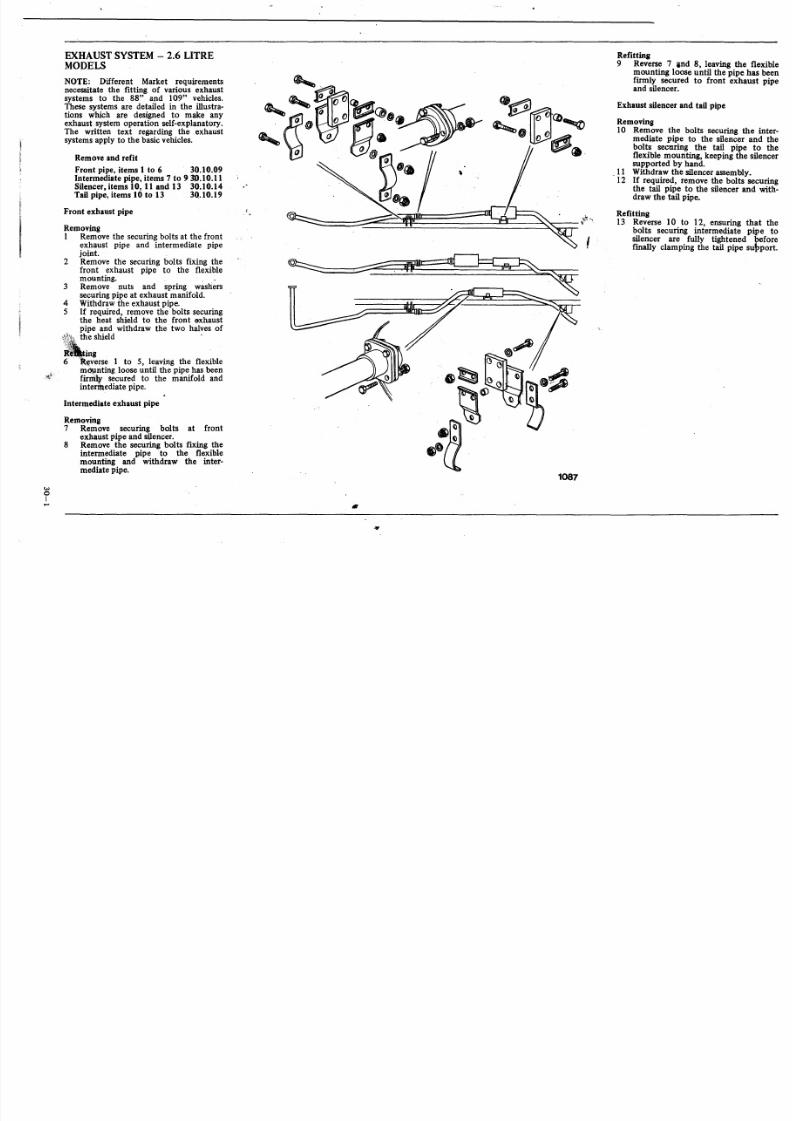
EXHAUST SYSTEM - 2.6 LITREMODELS
NOTE: Different Market requirementsnecessitate the fitting of various exhaustsystems to the 88" and 109" vehicles.These systems are detailed in the illustra-tions which are designed to make' anyexhaust system operation self-explanatory.The written text regarding the exhaust
systems apply to the basicvehicles.
Remove and refit
Front pipe, items 1 to 6 30.10.09Intermediate pipe, items 7 to 9 30.10.11Silencer, items 10,11 and 13 30.10.14Tail p ipe, items 10 t o 13 3Q.I0.19
Front exhaust pipe
Removing1 Remove the securingbolts at the front
exhaust pipe and intermediate pipejoint.
2 Remove the securing bolts fixing thefront exhaust pipe to the flexible
mounting. , ,3 Remove nuts and spring washers
securing pipe at exhaust manifold.4 Withdraw the exhaust pipe.S If required, remove the bolts securing
the heat shield to the front exhaustpipe and withdraw the two halves ofthe shield
" ing6~l'(verse 1 to 5, leaving the flexible
m~nting loose until the pipe has beenfirmly secured to the manifold andintermediate pipe.
Intermediate exhaust pipe
Removing7 Remove securing bolts at front
exhaust pipe and silencer.8 Remove the securing bolts fixing the
intermediate pipe to the flexiblemounting and withdraw the inter-mediate pipe.
w
oI
0"
Refitting
9 Reverse 7 and 8, leaving the flexiblemounting loose until the pipe has beenfirmly secured to front exhaust pipeand silencer.
Exhaust silencer and tail pipe
Removing
10 Remove the bolts securing the inter-
mediate pipe to the silencer and thebolts securing the tail pipe to theflexible mounting, keeping the silencersupported by hand.
11 Withdraw the silencer assembly.12 If required, remove the bolts securing
the tail pipe to the si lencer and with-draw the tail pipe.
Refitting
13 Reverse 10 to 12, ensuring that thebolts securing intermediate pipe tosilencer are fully tightened beforefinally clamping the tail pipe subport,
1087
8/3/2019 LAND ROVER SIII_ROM_Part_4Fuel Cont Exhaust, Coolant and Clutch and Gearbox
http://slidepdf.com/reader/full/land-rover-siiirompart4fuel-cont-exhaust-coolant-and-clutch-and-gearbox 14/50
woItv
EX HA US T S YS TEM - 214 LITREMODELS
NOTE: Different Marke t requirementsnecessi tate the f it ting of various exhaustsystems to the 88" and 109" vehicles.These systems are detai led in the illus tra-tions which are designed to make anyexhaust system operation self-explanatory.The written text regarding the exhaustsystems apply to the basic vehicles.
Remove and refit
Front pipeInterDlediate pipeSilencer and tail pipe
Front exhaust pipe
RemovingI Remove securing bolts at front
exhaust pipe and intermediate pipejoint.
2 Remove nuts and spring washers secur-ing pipe at exhaust manifold.
3 Withdnw the exhaust pipe and jointwasher.
30.10.0930.10.1130.10.22
Refitting4 Reverse I to 3.
InterDlediate exhaust pipe
Removing5 Remove securing bolts at front
exhaust pipe and silencer.6 Remove supporting clamp and with-
draw intermediate exhaust pipe.
Refitting7 Reverse 5 and 6, leaving the support-
ing clamps loose until the pipe ha sbeen secured fi rmly to front exhaust
pipe and silencer.
Exhaust siencer (Right hand steeringmodels only)
Removing8 Remove the bolts securing inter-
mediate pipe to sil encer and re leasesupport saddle from silencer tail pipe,keepinl silencer supported by hand.
9 WithdraW'silencer assembly.
Refitting10 Reverse 8 and 9, ensuring that the
bolts securing intermediate pipe tosilencer are fully tightened beforef inally clamping the tai l pipe support .
Exhaust silencer (Left hand steeringmodels)
RemovingII Remove bolts securing intermediate
pipe to silencer.12 Keeping the s ilencer supported, release
the supporting strap for s ilencer r ighthand side and saddle clamp on tailpipe, then withdraw silencer assembly.
Refitting13 Fit the silencer in posi tion and loosely
support by means of supporting strapand saddle clamp.
14 Secure the intermediate pipe tosilencer.
IS Finally tighten bolts securing supportstrap and saddle clamp.
•81086

8/3/2019 LAND ROVER SIII_ROM_Part_4Fuel Cont Exhaust, Coolant and Clutch and Gearbox
http://slidepdf.com/reader/full/land-rover-siiirompart4fuel-cont-exhaust-coolant-and-clutch-and-gearbox 15/50
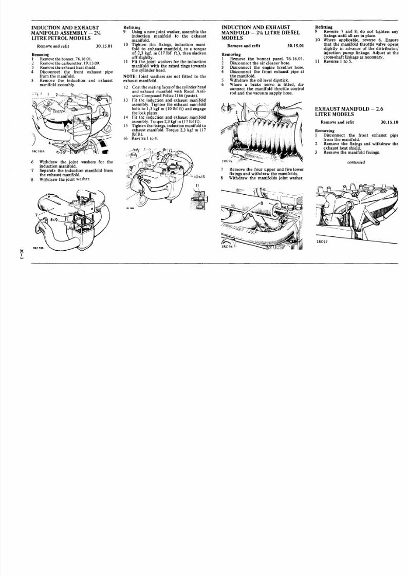
INDUCTION AND EXHAUSTMANIFOLD ASSEMBLY - 2%LITRE PETROL MODELS
Remove and refit 30.15.01
RemovingI Removethe bonnet. 76.16.0 I.2 Removethe carburetter. 19.15.09.3 Removethe exhaust heat shield.
4 Disconnect the front exhaust pipefrom the manifold.
5 Remove the induction and exhaustmanifold assembly.
6 Withdraw the joint washers for theinduction manifold.
7 Separate the induct ion manifold fromthe exhaust manifold.
8 Withdraw the joint washer.
woIw
Refitting9 Using a new joint washer, assemble the
induction manifold to the exhaustmanifold.
10 Tighten the fixings, induction mani-fold to exhaust manifold, to a torqueof 2,3 kgf, m (17 lbf. ft.), then slackenoff slightly.
11 Fit the joint washers for the inductionmanifold with the raised rings towards
the cylinder head.NOTE: Joint washers are not fit ted to theexhaust manifold.
12 Coat the mating facesofthecylinder headand exhaust manifold with Rocol Anti-seizeCompound Foliac JI66 (paste).
13 Fit the induction and exhaust manifoldassembly. Tighten the exhaust manifoldbolts to 1,3 kgf m (10 lbf ft) and engagethe lock plates.
14 Fit the induction and exhaust manifoldassembly. Torque 2,3 kgf m (17 lbfft).
15 Tighten the fixings,induction manifold toexhaust manifold. Torque 2,3 kgf m (17lbf ft).
16 Reverse I to 4 .
10&13
INDUCTION AND EXHAUSTMANIFOLD - 2% LITRE DIESELMODELS
Remove and refit 30.15.01
Refitting9 Reverse 7 and 8; do not tighten any
fixings until all are in place.10 Where appl icable, reverse 6. Ensure
that the manifold throttle valve openss lightly in advance of the dis tr ibutor /injection pump linkage. Adjust at thecross-shaft linkage as necessary.
11 Reverse 1 to 5.
EXHAUST MANIFOLD - 2.6LITRE MODELS
Remove and refit 30.15.10
1RCHItA
II
•,
c
.
;c
Removing1 Remove the bonnet panel. 76.16.01.2 Disconnect the ai r cleaner hose.3 Disconnect the engine breather hose.
4 Disconnect the front exhaust pipe atthe manifold.
5 Withdraw the oil level dipst ick.6 Where a brake servo is fitted, dis-
connect the manifold throttle controlrod and the vacuum supply hose.
7 Remove the four upper and five lowerfixings and withdraw the manifolds.
8 Withdraw the manifolds joint washer.
Removing1 Disconnect the front exhaust pipe
from the manifold.
2 Remove the fixings and withdraw theexhaust heat shield.
3 Remove the mani fold fixings.
continued

8/3/2019 LAND ROVER SIII_ROM_Part_4Fuel Cont Exhaust, Coolant and Clutch and Gearbox
http://slidepdf.com/reader/full/land-rover-siiirompart4fuel-cont-exhaust-coolant-and-clutch-and-gearbox 16/50
4 Withdraw the manifold.S Withdraw the joint washers.
Refitting
6 Reverse 3 to S with the joint washersplain faces toward the engine. Tightenthe fixings evenly to avoid distortion.
7 Reverse 1 a nd 2.

8/3/2019 LAND ROVER SIII_ROM_Part_4Fuel Cont Exhaust, Coolant and Clutch and Gearbox
http://slidepdf.com/reader/full/land-rover-siiirompart4fuel-cont-exhaust-coolant-and-clutch-and-gearbox 17/50
CLUTCH ASSEMBLY
Remove and refit 33.10.01
Service tool: 605022 Clutch plate align-ment gauge
NOTE: If it is required to remove thec lutch only, it is not necessary to removethe seat base nor complete ly remove thegearbox. Proceed with the gearbox removal37.20.01, but only withdraw the gearboxrearward approximately 130 mm (5 in.), togiveaccessto the clutch fixings.
Remov ing1 Remove the front f loor . 76.10.12.2 Remove the front seat base. 76.70.06.3 Remove the gearbox assembly.
37.20.01.4 Mark the clutch cover f it ted posit ion
relative to the flywheel.5 Do not dis turb the three bolts located
in the apertures in the clutch cover.6 Remove the clutch assembly.7 Withdraw the clutch driven plate.
Refitting8 Smear the splines of the primary pinion,the clutch centre and the withdrawal unitabutment faces with Molybdenum disul-phide grease such as Rocol MTS 1000.
9 Reverse 6 and 7 locating the driven platewi th the side marked 'Flywheel side 'towards the flywheel,and ensure that theclutchcoverand flywheelassemblymarksare aligned. Centralising tool 605022.
10 secure the coverfixingsevenly,using diag-onal selection.Torque 3,0to 3,5kgfm (22to25 Ibf ft).
II Reverse I to 3.
DATA
Clutch driven plate diameter .Damper springs colour identification .
wwI
CLUTCH ASSEMBLY
Overhaul 33.10.08
HYDRAULIC SYSTEM
Bleed 33.15.01
0770
Clutch assemblyThe clutch assembly is of the diaphragmspring type and no overhaul procedures areapplicable. Repair is by replacement only.
Clutch driven plateExamine c lutch driven plate for wear andsigns of oi l contaminat ion. Examine allrivets for pulling and distortion, rivets mustbe below the frict ion surface . If oil con-tamination is present on the friction liningsor if they are appreciably worn, replace theclutch driven plate assembly complete oralternatively, replace the frict ion liningsfollowing standard workshop practices.
241,3 mm (9.5 in. ).Dark green.
ProcedureNOTE: During the procedure, keep thefluid reservoir topped up to avoid introduc-ing further air into the system. Use onlythe recommended type of hydraulic f luid.Division 09 refers.
Attach a length of suitable tubing tothe slave cylinder bleed screw.
2 Place the free end of the tube in a glassjar containing clutch fluid.
3 Slacken the bleed screw.4 Pump the clutch pedal , pausing at the
end of each stroke, until the fluidissuing from the tubing is free of airwith the tube free end below thesurface of the fluid in the container.
5 Hold the tube free end immersed andtighten the bleed screw when com-mencing a pedal down stroke.
MASTER CYLINDER
Remove and refit 33.20.01
Removing1 Remove the bonnet. 76.16.01.
Left hand steering models 2-12.
2 Remove the left hand side front wingrear top section retaining bolt.
3 Remove the two nuts/bolt s securingthe lower wing edge to the sill panel.
4 Remove the four nuts/bolts securingthe splash plate to the bulkhead.
5 Remove the three bolts securing thesplash plate to the wing.
6 Remove the splash plate.·7 Remove the four bolts securing the
rea r vertical wing edge to the 'A' postsection.8 Disconnect the hydraulic pipe from
the clutch master cylinder plug aper-ture to prevent leakage.
9 Remove the brake pipe clip from theclutch pedal cover and disconnect thereturn spring.
10 Remove the six bolts securing theclutch pedal box.
continued

8/3/2019 LAND ROVER SIII_ROM_Part_4Fuel Cont Exhaust, Coolant and Clutch and Gearbox
http://slidepdf.com/reader/full/land-rover-siiirompart4fuel-cont-exhaust-coolant-and-clutch-and-gearbox 18/50
~ 11 Ease away the rear section of the wingI panel.N 12 Manoeuvre out the clutch pedal box
assembly.
Right hand steering models.
13 Disconnect the fluid pipe from themaster cylinder.
Allmodels
14 Remove the top cover and gasket fromthe clutch pedal bracket.
15 Remove the fixings from the end ofthe master cylinder push rod.
16 Detach the master cylinder from thepedal bracket.
17 Drain the fluid from the cylinder.
Refitting18 Secure the cylinder to the pedal
bracket, adjust the push rod lever togive 1,55 mm (0.062 in.) free playbetween the push rod and the piston,6 mm (0.25 in.) at the pedal. Tighten
the locknuts. See clutch pedal andmaster cylinder setting. 33.20.02.
19 Fit the gasket to the top cover.
Right hand steering models
20 Connect the fluid pipe to the master
cylinder.
Left hand steering models
21 Refit the clutch master cylinder assem-bly to the vehicle. Ensure that thepedal return spring is connected.
22 Connect the hydraulic pipe.23 Secure the brake pipe clip.
Allmodels
24 Bleedthe clutch system. 33.15.01.25 Check the pedal free play, 6 mm (0.25
in.). Check the pedal lever height fromthe floor, 140 mm (5.50 in.).
26 Reverse 1to 7.
MASTER CYLINDER
Overhaul 33.20.07
8 Withdraw the springand retainer.9 Withdraw the valve spacer and spring
washer from the valve stem.10 Remove the valve seal.
Inspecting11 Clean all components in Girling clean-
ing fluid and allow to dry.12 Examine the cylinder bore and piston,
ensure that they are smooth to thetouch with no corrosion, score marks
or ridges. Ifthere isany doubt, fit newreplacements.
13 The seals should be replaced with newcomponents.
Assembling14 Smear the seals with Castrol-Girling
rubber grease and the remaininginternal items with Castrol-GirlingBrake and Clutch Fluid.
Dismantling1 Remove the master cylinder. 33.20.01.2 Remove the circlip.3 Withdraw the push rod and retaining
washer.4 Withdraw the piston assembly. If
necessary, apply a low air pressure tothe outlet port to expel the piston.
1 Re 671
5 Prise the locking prong of the springretainer clear of the piston shoulderand withdraw the piston.
6 Withdraw the piston seal.7 Compress the spring and position the
valve stem to align with the larger holein the spring retainer.

8/3/2019 LAND ROVER SIII_ROM_Part_4Fuel Cont Exhaust, Coolant and Clutch and Gearbox
http://slidepdf.com/reader/full/land-rover-siiirompart4fuel-cont-exhaust-coolant-and-clutch-and-gearbox 19/50
15 Fit the valve seal, flat side first, on tothe end of the valve stem.
16 Place the spring washer , domed sidefirst, over the small end of the valvestem.
17 Fit the spacer, legs f irst .
18 Place the coil spring over the valvestem.
19 Insert the retainer into the spring.20 Compress the spring and engage the
valve stem in the keyhole slot in theretainer.
ININ
IIN
21 Fit the seal , large diameter last, to thepiston.
22 Insert the piston into the spring
retainer and engage the locking prong.
lRC445
23 Smear the pis ton with Castrol-Girl ingrubber grease and insert the assembly,valve end first, into the cylinder.
24 Fit the push rod, retaining washer andcirclip.
25 Rem the master cylinder. 33.20.01.
CLUTCH RELEASE ASSEMBLY
Remove and refit 33.25.12
t
7 Remove the spring clip and fixings.8 Withdraw the release lever assembly.
Refitting9 Reverse I to 8. Lubricate the bearing
s leeve inner diameter with PBC (PolyButyl Cuprysil) grease.
CLUTCH PEDAL
Remove and refit 33.30.02
RemovingI Remove the front floor.76.10.12.2 Removethe front seat base. 76.70.06.3 Removethe gearbox. 37.20.01.4 Removethe clutch slave cylinder5 Withdraw the retainer staple.6 Withdraw the bearing and sleeve. If
required, press the bearing off the sleeve.Fit the replacement bearing wi th thedomed faceoutwards from sleeve.
Removing1 Remove the bonnet. 76.16.01.2 Left hand steering models. See
33.20.01.3 Disconnect the fluid pipe from the
clutch master cylinder.4 Disconnect the return spr ing from the
clutch pedal.5 Remove the fixings securing the clutch
pedal bracket from inside the vehic lecab.
6 Withdraw the bracket complete withpedal and master cylinder.
7 Remove the top cover and gasket fromthe clutch pedal bracket.
8 Remove the fixings from the end ofthe master cylinder push rod and pushthe rod into the master cylinder toclear the pedal trunnion.
9 Using a suitable punch, drift out thepin from the pedal shaft.
10 Withdraw the pedal shaft .11 Withdraw the clutch pedal complete
with trunnion and bushes.12 If required, remove the bushes, trun-
nion and distance piece from theclutch pedal.
Refitting13 Ifremoved,fit the distance piece,trunnion
and bushes to the clutch pedal. Lubricatethe trunnion and distance piece with gen-eral purpose grease on assembly. Newpedal bushes must bereamed to 19,05mm± 0,02mm (0.750 in ± 0.001 in).
continued

8/3/2019 LAND ROVER SIII_ROM_Part_4Fuel Cont Exhaust, Coolant and Clutch and Gearbox
http://slidepdf.com/reader/full/land-rover-siiirompart4fuel-cont-exhaust-coolant-and-clutch-and-gearbox 20/50
wwI~
14 Remove the oi l plug and washer fromthe pedal shaft. Fill the shaft borewith clean engine oil and ref it the plugand washer.
15 Reverse 8 to 11.16 Place the gasket in position on the
securing flange of the brake pedalbracket. If necessary, use Bostik adhe-siveto retain the gasket.
17 Reverse 3 to 6.18 Bleed the clutch hydraulic system.
33.15.01.
C l u tc h p ed a l a n d ma s te r c y li n de r s e tt in g19 Remove the top cover and slacken both
locknutson the master cylinder push-rod.20 Check the distance from the lower
edge of the clutch pedal to the floor.The correct distance is 140 mm (5.5in.).
21 Adjust the pedal stop, as required, toobtain the correct distance.
22 Adjust the master cylinder push roduntil there is approximate ly 1,5 mm(0.062 in. ) f ree play between the pushrod and the master cylinder piston.
23 Tighten both locknuts.24 Check the clutch pedal and ensure that
the re is a minimum of 6 mm (0.250
in.) free movement of the pedal beforepressure is felt. If necessary, readjustthe master cylinder push rod.
25 Fit the gasket and top cover to theclutch pedal bracket.
26 Reverse 1 and 2.
DATA
Clutch pedal pivot bushes, reameddiameter , .
Clutch pedal height setting .Master cylinder push rod free play .Clutch pedal free play (minimum) .
20
I
lRC666
SLAVE CYLINDER
Remove and refit 33.35.01
SLAVE CYLINDER
Overhaul 33.35.07
15,87 mm± 0,02 mm (0.750 in.±0.001 in.)140 mm (5.500 in.).
1,5 mm (0.062 in. ).6 ,0 mm (0.250 in. ).
Remov ing1 Unscrew the bleed valve to release the
hydraulic fluid.2 Disconnect the f luid supplypipefromthe
slave cylinder.3 Remove the two bolts securing the slave
cylinder.4 Withdraw the slave cylinder.
Refitting5 Enter the push-rod through the holeinthe
rubber boots so that it locates correctlyinside the cylinder.
6 Fit the slave cylinder bleed valve upper-most, and secure with the two bolts.
7 Fit the fluid supply pipe.8 Bleed the clutch hydraulic system as
described in operation 33.15.01.9 Check the sys temforleaks withthe brake
pedal depressed and with the system atrest.
10 Fit the fluid pipe.
24RC306A
Dismantling1 Remove the slave cylinder. 33.35.01.2 Withdraw the dust cover.3 Expel the piston assembly, applying
low pressure air to the f luid inlet .4 Withdraw the spring.
Inspecting5 Clean all components with Girling
cleaning fluid and allow to dry.6 Examine the cylinder bore and piston,
ensure that they are smooth to thetouch with no corrosion, score marksor ridges. If there is any doubt, fit newreplacement.
7 The seal should be replaced with a newcomponent.
Assembling8 Smear the seal with Castro1-Girling
rubber grease and the remaininginternal i tems with Castrol -Girl ingbrake and clutch fluid.
9 Fit the seal, large diameter last, to thepiston.
10 Locate the conical spring, small dia-meter first, over the front end of thepiston.
11 Smear the pis ton with Castrol-Girl ingrubber grease and inser t the assembly,spring end first, into the cylinder.
12 Fil l the dus t cover with Castrol-Girl ingrubber grease and fit the cover to thecylinder.
13 Refit the slave cylinder. ~3.35.01.

8/3/2019 LAND ROVER SIII_ROM_Part_4Fuel Cont Exhaust, Coolant and Clutch and Gearbox
http://slidepdf.com/reader/full/land-rover-siiirompart4fuel-cont-exhaust-coolant-and-clutch-and-gearbox 21/50
F R ON T O U TP U T S HA F T H O US IN G F RO NT O UT PU T S HA FT H OU SIN G
Remove and refit 37.10.05
Removing1 Remove the front floor. 76.10.12.2 Remove the seat base. 76.70.06.3 Drain the gearbox lubricating oil.4 Remove the transmission brake.
70.45.16.5 Remove the transfer box. 37.29.25.6 Removethe transfer gear selector shaft
plunger.7 Remove the top cover from the trans-
fer box.8 Remove the pinch bolt from the trans-
fer selector fork.9 Remove the front output shaft
housing from the transfer box, takingcare to catch the four wheel drivelocking dogwhich willbe released.
10 Withdraw the loose selector fork fromthe transfer box.
Refitting11 If the selector shafts have been
removed, refer to 37.10.06 for refit-
ting procedure.12 Place the transfer gear selector fork in
position, with the threaded sideof thepinch bolt hole towards the centre ofthe transfer box.
13 Smear both sides of the joint washerwith a general purpose grease andplace in position on the transfer box.
14 Offer the output shaft housing to thetransfer box, carefully locating thetransfer gear selector shaft through theselector fork by turning the flange ifnecessary to engage the splines of thelocking dogover the output shaft.
IN-..)
I
,.lRe44
15 Complete the refitting by reversing theremoval procedure. Ensure that theselector fork pinch bolt engages thegroove in the selector shaft. This boltwill fit only one way.
16 If the transfer box is of the all helicaltype, see 37.29.28, adjust the transfertravel stop as follows.
17 Engage four wheel drive, low ratio,and check the fit of the four wheeldrive locking pin in the pivot shaft.The pin must be aneasy slide fit.
18 If necessary, adjust the stop bolt toobtain this condition.
19 Tighten the locknut to secure the stopbolt.
20 Replenish the gearbox oil.
Overhaul 37.10.06
Dismantling the housing1 Remove the front output shaft
housing. 37.10.05.2 Removethe link from the transfer gear
selector shaft.3 Remove the four wheel drive control
lever.
4 Remove the selector shaft dust cover.5 Withdraw the selector shaft assemblies
and the four wheel drive locking dogfrom the housing.
continued
8/3/2019 LAND ROVER SIII_ROM_Part_4Fuel Cont Exhaust, Coolant and Clutch and Gearbox
http://slidepdf.com/reader/full/land-rover-siiirompart4fuel-cont-exhaust-coolant-and-clutch-and-gearbox 22/50
6 Remove the flange from the frontoutput shaft.
7 Remove the oil seal retainer andgasket.
8 Press out the oil seal.9 Remove the front output shaft from
the housing.
10 Press out the bearing from thehousing.
11 Remove the sea ling rings for the fourwheel dr ive locking pin and the trans-fer gear shaft.
Dismantling the four wheel drive selectorshaft12 Remove the block from the selector
shaft.13 Withdraw the spr ings and selector fork
from the shaft.
Dismantling the transfer gear selector shaft14 Slide the distance tube, bush, spring
and pivot shaft assembly from theselector shaft.
IS Remove the block.16 Remove the connector from the pivot
shaft.17 Remove the coupling from the pivot
shaft.
Dismantling the front output shaft18 Remove the f ixings.19 Lift the two halves of the oil thrower
from the shaft.
l R C 5 5
Inspecting20 Renew any components which show
obvious wear or damage. Examine thebush in the four wheel drive controllever and renew if necessary.
21 Examine the four wheel drive selectorfork and bushes, and renew as neces-sary. New bushes must be pressedflush with the end faces of the forkboss , and reamed in position to 15,887mm + 0,012 mm (0.6255 in. + 0.0005
in.) diameter, and must be a s liding fiton the selector shaft.22 Check the four wheel drive selector
shaf t spr ings, the free length should be69,8 mm (2.75 in. ).
I RC 54
23 Check the transfer selector shaftspring, the free length should be181,76 mm (7.156 in.).
24 Examine the bush in the rear end ofthe front output shaft. The bush mustbe a sliding fit on the front end of thetransfer box output shaft and must befirmly retained in its bore. If bushreplacement is necessary, press thenew bush flush with the end of theshaft and ream in posi tion to 22,2 mm± 0,013 mm (0.8755 in. ± 0.0005 in.)diameter.
Assembling the front output shaftNOTE: Ifa new output shaf t is being fittedtry the bronze bush over the front end ofthe rear output shaft and ensure that it isnot tight to prevent subsequent seizure.
25 Fit the oil thrower to the front outputshaft, do not ful ly t ighten the fixingsat this stage.
26 Position the oil thrower 25 mm (1 in.)from the shoulder on the shaft, asillustrated.
27 Tighten the f ixings .
Assembling the transfer gear selector shaft28 Fit the connector to the pivot shaft
noting the relat ionship of the counter-sink in the hole at the other end of theshaft.
29 Do not fully tighten the fixings at thisstage.
30 Fit the coupling to the pivot shaftlocating the extended arm correctly, asillustrated.
I R C 5 6
31 Fit the block to the transfer gearselector shaft, loca ting the fixings sothat the nut and split pin are on thesame side of the shaft as the plungergrooves. .
32 Locate the pivot shaft assembly- inposit ion on the t ransfe r gear selectorshaft.
33 Engage the coupling with the specialscrew.

8/3/2019 LAND ROVER SIII_ROM_Part_4Fuel Cont Exhaust, Coolant and Clutch and Gearbox
http://slidepdf.com/reader/full/land-rover-siiirompart4fuel-cont-exhaust-coolant-and-clutch-and-gearbox 23/50
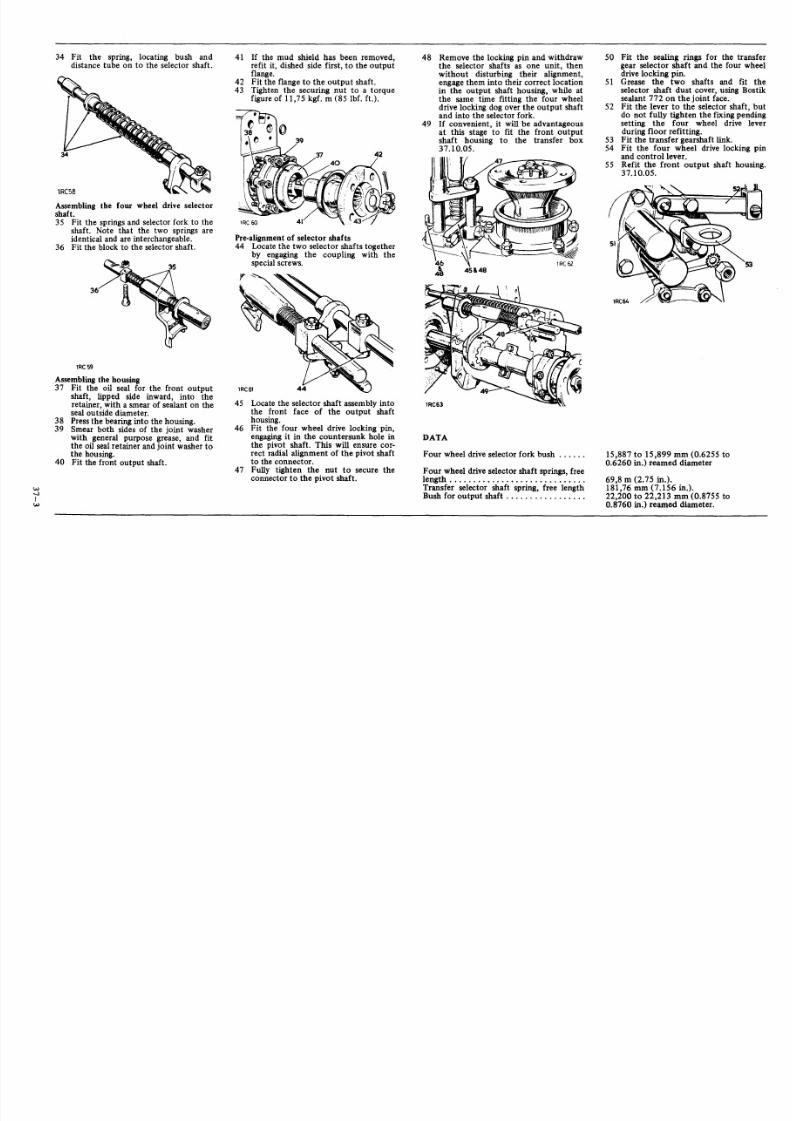
34 Fit the spring, locating bush anddis tance tube on to the selector shaft .
lRC58
Assembling the four wheel drive selectorshaft.35 Fit the springs and se lector fork to the
shaft. Note that the two springs areidentical and are interchangeable.
36 Fit the block to the se lector shaft .
lRC59
Assembling the housing37 Fit the oil seal for the front output
shaft, lipped side inward, into theretainer , with a smear of sealant on theseal outside diameter.
38 Press the bearing into the housing.39 Smear both sides of the joint washer
with general purpose grease, and fitthe oil seal retainer and joint washer tothe housing.
40 Fi t the front output shaft .
W-.I
Iw
41 If the mud shield has been removed,refi t i t, d ished s ide f irst , to the outputflange.
42 Fit the flange to the output shaft.43 Tighten the securing nut to a torque
f igure of 11,75 kgf . m (85 lbf. f t. ).
Pre-alignment of selector shafts44 Locate the two selector shafts together
by engaging the coupling with thespecial screws.
45 Locate the selector shaf t assembly intothe front face of the output shafthousing.
46 Fit the four wheel drive locking pin,engaging it in the countersunk hole inthe pivot shaft. This wi ll ensure cor-rect radial alignment of the pivot shaftto the connector.
47 Fully tighten the nut to secure theconnector to the pivot shaft .
48 Remove the locking pin and withdrawthe selector shafts as one unit, thenwi thout di sturbing thei r a lignment,engage them into their correct locationin the output shaft housing, while atthe same time fitting the four wheeldrive locking dog over the output shaftand into the selector fork.
49 If convenient, it will be advantageousat this stage to fit the front output
shaft housing to the transfer box37.10.05.
DATA
Four wheel drive selector fork bush
Four wheel drive selector shaft springs, freelength .Transfer selector shaf t spr ing, free lengthBush for output shaft .
50 Fit the sealing rings for the transfergear selector shaft and the four wheeldrive locking pin.
51 Grease the two shafts and fit theselector shaft dust cover , us ing Bostiksealant 772 on the joint face,
52 Fit the lever to the selector shaft, butdo not fully t ighten the f ixing pendingsetting the four wheel drive leverduring floor refitting.
53 Fit the transfer gearshaft l ink.54 Fit the four wheel drive locking pin
and control lever.55 Refit the front output shaft housing.
37.10.05.
15,887 to 15,899 mm (0.6255 to0.6260 in.) reamed diameter
69,8 m (2.75 in.).181,76 mm (7.156 in.).22,200 to 22,213 mm (0.8755 to0.8760 in.) reamed diameter.

8/3/2019 LAND ROVER SIII_ROM_Part_4Fuel Cont Exhaust, Coolant and Clutch and Gearbox
http://slidepdf.com/reader/full/land-rover-siiirompart4fuel-cont-exhaust-coolant-and-clutch-and-gearbox 24/50
B E L L H O U SI NG B E L L H O US IN G
Remove and refit 37.12.07
Removing1 Remove the front floor. 76.10.122 Remove the seat base. 76.70.06.3 Drain the gearbox lubrica ting oil .4 Remove the gearbox assembly com-
plete. 37.20.01.5 Remove the main gearchange lever.
37.16.04.
6 Remove the clutch withdrawal unit.33.25.12.7 Disconnec t the transfer gear lever from
the bracket at the bell housing. Thefixings illustrated are alternatives.
8 Withdraw the lever, taking care toretain the spring strip located betweenthe lever ball and link.
lRC65
9 Fully adjust the transmission brake tolock 'hard on' .
10 Remove the primary pinion cover andoil seal assembly.
11 Withdraw the joint washer .12 Select any gear.13 Remove the layshaft secur ing bolt and
washer. DO NOT remove the circ lipfrom the primary pinion.
14 Remove the bell housing fixings.
15 Retain the constant gear and conicaldistance piece which are releasedduring the following procedure.
16 Hold the 1ayshaf t depressed fully rear-wards and ease the housing from thegearbox.
Refitting17 Two of the bell housing to gearbox
fixings are special fitted bolts, andmust be positioned diagonally op-posite each other.
18 Smear both sides of the joint washerwith a general purpose grease andplace in position on the gearbox.
19 Ensure that the roller bearing for theprimary pinion is in position.
20 Locate the conical distance piece andconstant gear in place, in mesh withthe primary pinion, on the rear face ofthe bell housing.
21 Retain the constant gear and conicaldis tance piece in pos it ion, by holdingthrough the layshaf t bearing from theinside of the bel l housing, then offe rthe bell housing to the gearbox, usingspecial care to a lign the constant gear
with the splines on the layshaft.NOTE: Ifthe layshaft securing bolt has anylon locking patch it should be discardedin favour of the lates t standard setbolt .Smear with Loctite 601 and tighten to 6,9kgf m (50 lbf ft).
22 Complete the reassembly byreversing I to14.Smear the layshaft securing bolt withLoctite 601 and tighten to a torque figureof6,9kgfm (50 lbf ft).
23 Check and repleni sh the gearbox lubri-cating oil.
24 Adjust the transmission brake.
70.45.09.
Overhaul 37.12.08
Dismantling1 Remove the be ll housing. 37.12.07.2 Remove the layshaft bearing retainer
and bearing plate.3 Press the lay s haft bearing from the bell
housing.
456
7
Remove the circIip and distance washer.Press out the primary pinion.Remove the bearing retaining plates.
NOTE: These are handed plates.Press out the primary pinion bearing.

8/3/2019 LAND ROVER SIII_ROM_Part_4Fuel Cont Exhaust, Coolant and Clutch and Gearbox
http://slidepdf.com/reader/full/land-rover-siiirompart4fuel-cont-exhaust-coolant-and-clutch-and-gearbox 25/50
Assembling8 Reverse 5 t o 79 Fit the distance washerandposition a new
circlip in the retaining groove.10 Check the end-float between the primary
pinion and the distance washer. End-floatmust be the minimum obtainable, select-ing a suitable distance washer from therange available. It should be possible toturn the washer without feeling any end-
float.II Fit the selec ted di stance washer andcirclip.
12 Reverse I to 3.
GEARBOX MAIN CASING
Remove and refit 37.12.40
NOTE: If it isrequired tochange the rear mainoil seal only, it is not necessary to completelydismantle thegearbox. The oilseal isaccessibleafter removing the intermediate gear and themainshaft gear from the transfer box, see37.29.25 and 37.20.25 fordetails.
RemovingI Remove the front floor. 76.10.12.
2 Remove the seat base. 76.70.06.3 Dra in the gearbox lubricating oil.4 Remove the gearbox assembly com-
plete. 37.20.01.5 Remove the transmission brake.
70.45.16.6 Remove the transfe r box. 37.29.2S.7 Remove the main gear change lever.
37.16.04.8 Remove the clutch withdrawal unit.
33.25.12.
lRC73
9 Remove the bell housing. 37.12.07.10 Remove the selector shaf ts . 37.16.31.11 Remove the layshaft. 37.20.19.12 Remove the mainshaft. 37.20.25.13 When 1 to 12 are completed the
gearbox main casing i s re leased andcan be dismantled as described under'Overhaul', 37.12.43.
Refitting14 Reverse 1 to 12.
GEARBOX MAIN CASE
Overhaul 37.12.43
4 Press out the housing, complete withbearing, in a forward direction.
5 Remove the circlip.6 Press the mainshaft rear bearing from
the housing.7 With the case warm, drive out the
layshaft bearing outer race, using asuitable drift applied through the twoextractor holes provided in the caserear face. (See also item 8.)
8 An alternative method is to use amandrel, approximately 300 mm (12in.) long by 43,50 mm (1.687 in.)diameter, so that it is a tight fit in theouter race. Warm the gearbox case andouter race, keep the mandrel ascool aspossible. With the casing warm, insertthe mandrel into the oute r race whichwill shrink on to the mandrel andwithdraw easily.
9 The remaining oil drain and fillerplugs, studs, dowels and retaining platefor selector shaft oil seals, can beremoved as required. See 37.20.13 forremoval of reverse idler gear and shaftif required.
Inspecting10 Check all components for wear and
damage.11 Ensure that the two dowels in the
gearbox top face , and the two dowelsin the rear face, are secure.
Assembling12 Press the layshaft rear bearing outer
race, lipped edge fi rst, into the gear-box case.
13 Smear the outside diameter of the main-shaft rear bearing with Loctite RetainingCompound, Grade 60Ind pressthe bear-ing into the housing.
14 Retain with a circlip.15 Fit the main shaft rear oilseal,lipped side
first, into the bearing housing.16 Smear the outside diameter ofthe bearing
housing with Locti te Retaining Com-
pound (Grade 601), Part No. 600303 andpress it into position.
8
DismantlingI Remove the gearbox main case.
37.12.40.2 Prise the oil seal from the rear of the
mainshaft bearing housing.3 Remove the circlip retaining the bear-
ing housing to the rear face of thegearbox.
NOTE: The gearbox should not be filledwith lubricating oil or used for twenty-fourhours, to allow the Loctite to fully cure.
17 Fit the retaining circlip to the groovein the bearing housing where it pro-trudes through the rear face of thegearbox.
18 Refi t the gearbox main case. 37.12.40.
8/3/2019 LAND ROVER SIII_ROM_Part_4Fuel Cont Exhaust, Coolant and Clutch and Gearbox
http://slidepdf.com/reader/full/land-rover-siiirompart4fuel-cont-exhaust-coolant-and-clutch-and-gearbox 26/50
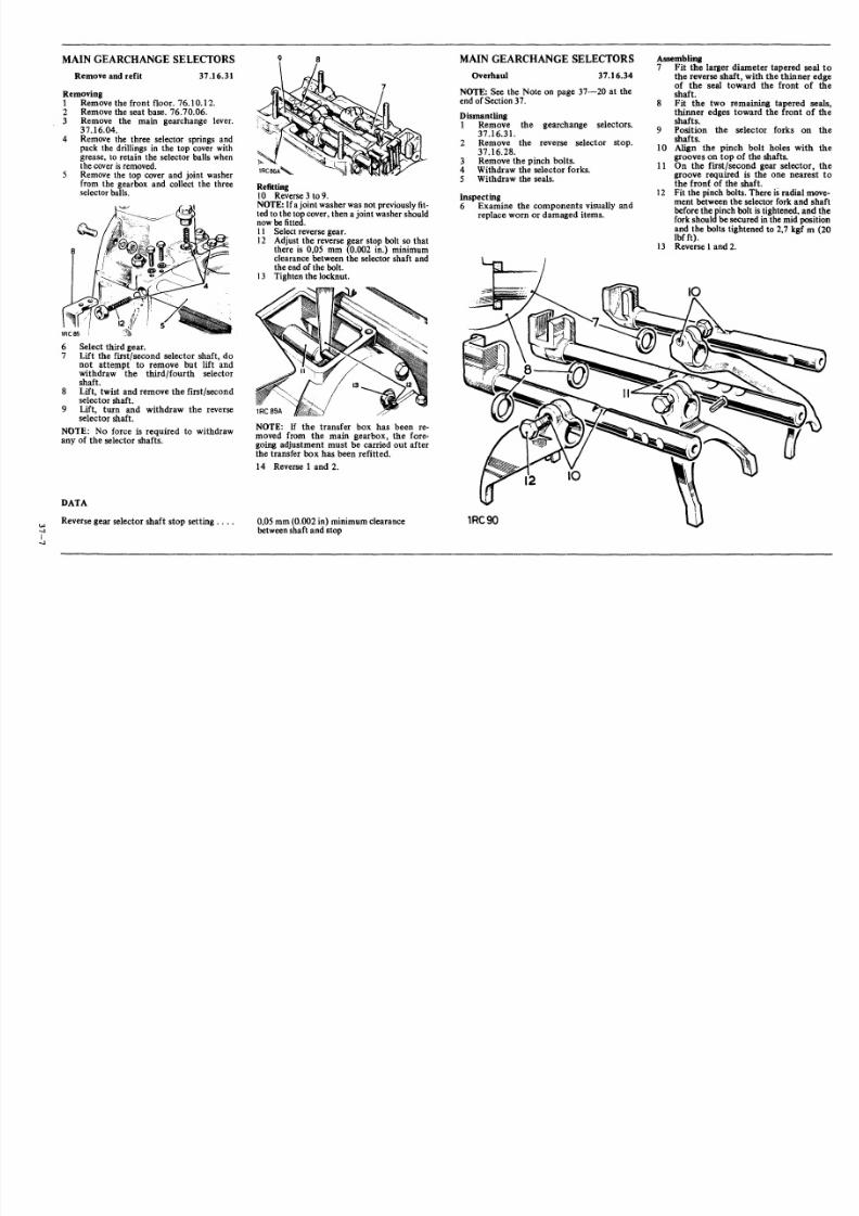
MAIN GEARCHANGE LEVER
Remove and refit 37.16.04
Removing1 Remove the front floor. 76.10.12.2 Remove the fixings.3 Remove the main gearchange lever
complete.4 To prevent loss, lift off the top cover
plate and rubber seal from the bellhousing.
Refitting
5 Reverse I to 4, noting that a retainingclip for the speedometer cable locatesunder the head of the front left handgearchange lever securing bolt.
MAIN GEARCHANGE LEVER
Overhaul 37.16.10
Assembling10 Reverse 2 to 8.11 Ensure that the lever locating pin
engages the slot in the lever ball.12 Secure the pin by peening.13 Refit the gearchange lever. 37.16.04.
REVERSE STOP FOR MAINGEARCHANGE LEVER
Remove, refit and adjust 37.16.28
DismantlingI Remove the gearchange lever.
37.16.04.2 Remove the fixings at the mounting
plate.3 Remove the lever housing from the
mounting plate.4 Removethe lever housing circlip.
5 Withdraw the spring, rubber '0' ring(later models) and sphericalseat.
7 Lift out the gearchange lever.8 Withdraw the lever balllocating pin.9 Examine the components visually and
renew any that show obvious wear ordamage. Removing
I Remove the front floor. 76.10.12.2 Removethe hinge adjuster.3 Remove the hinge and bracket from
the reverse selector shaft.4 Detach the two springs.
Refitting5 Reverse 1 to 4. Adjust the reverse stop
before fitting the front floor, items 6to 9.
Adjusting6 Release the fixings and slide the re-
verse stop inspection cover up the fourwheel drive selector lever.
NOTE: If the gearbox cover does notincorporate an inspection cover, then the
adjustment must be carried out before thegearbox cover is fitted.
7 Slacken the adjusting screw locknut.8 Adjust the screw so that the hinge
rides easily up the gear lever whenreverse gear is selected, while at thesame time appreciable resistance is felton moving the gearlever to the reverseposition.
9 Ensure that 1st gearengagescorrectly,if there is any tendency to simul-taneously engage reverse gear, readjustthe reverse stop.

8/3/2019 LAND ROVER SIII_ROM_Part_4Fuel Cont Exhaust, Coolant and Clutch and Gearbox
http://slidepdf.com/reader/full/land-rover-siiirompart4fuel-cont-exhaust-coolant-and-clutch-and-gearbox 27/50
MAIN GEARCHANGE SELECTORS MAIN GEARCHANGE SELECTORS Assembling7 Fit the larger diameter tapered seal to
the reverse shaft , with the thinner edgeof the seal toward the front of theshaft.
8 Fit the two remaining tapered seals,thinner edges toward the front of theshafts.
9 Position the selector forks on theshafts.
1 0 Align the pinch bolt holes with thegrooves on top of the shaf ts .
liOn the first/second gear selector, thegroove required is the one nearest tothe front of the shaft.
12 Fit the pinch bolts . There is radial move-ment between the selector fork and shaftbefore theJinch bolt istightened, and theforkshoul besecured inthe mid positionand the bolts t ightened to 2,7 kgf m (20lbfft).
13 Reverse I and 2.
Remove and refit 37.16.31
Removing1 Remove the front floor. 76.10.12.2 Remove the seat base. 76.70.06.3 Remove the main gearchange lever.
37.16.04.4 Remove the three selector springs and
pack the dr il lings in the top cover withgrease, to retain the selector balls whenthe coveris removed.
5 Remove the top cover and joint washerfrom the gearbox and collect the threeselector balls.
6 Select third gear.7 Lift the f irst /second selector shaf t, do
not attempt to remove but lift andwithdraw the third/fourth selectorshaft.
8 Lift, twist and remove the fi rst/secondselector shaft.
9 Lift, turn and withdraw the reverseselector shaft.
NOTE: No force is required to wi thdrawany of the selector shafts.
DATA
. . . . ,-..I
I-..I
Reverse gear selector shaft stop setting ... .
9 8
Refitting10 Reverse 3 to 9.NOTE: Ifajoint washer wasnot previously fit-tedto the top cover, then a joint washer shouldnowbe fitted.II Select reverse gear.12 Adjus t the reverse gear s top bolt so that
there is 0,05 mm (0.002 in.) minimumclearance between the selector shaft andthe end ofthe bolt.
13 Tighten the locknut.
NOTE: If the transfer box has been re-moved from the main gearbox, the fore-going adjustment must be carried out after
the transfer box has been refitted.14 Reverse 1 and 2.
0,05 mm(0.002 in) minimum clearancebetween shaft and stop
Overhaul 37.16.34
NOTE: See the Note on page 37-20 at theend ofSection 37.
DismantlingI Remove the gearchange selectors.
37.16.31.2 Remove the reverse selector stop.
37.16.28.3 Remove the pinch bolts.4 Withdraw the selector forks.5 Withdraw the seals.
Inspecting .6 Examine the components visually and
replace worn or damaged items.
lRC90

8/3/2019 LAND ROVER SIII_ROM_Part_4Fuel Cont Exhaust, Coolant and Clutch and Gearbox
http://slidepdf.com/reader/full/land-rover-siiirompart4fuel-cont-exhaust-coolant-and-clutch-and-gearbox 28/50
W
-...J
I00
GEARBOX ASSEMBLY
Remove and refit 37.20.01
Removing1 Remove the front floor. 76.10.12.2 Remove the seat base. 76.70.06.3 Drain the gearbox lubricating oil.4 Remove the rear propeller shaft fixings
at the transmission brake.5 Move aside the shaft.
6 Remove the front propeller shaft fix-ings at the front output coupling.
7 Move aside the shaft.
NOTE: If the vehicle is fitted with anyoptional equipment dr iven from the gear-box, it must be disconnected at the gear-box. Refer to separate publication fordetails of optional equipment.
8 Disconnect the hand brake expanderrod from the relay lever.
9 Remove the brake lever and relayfixings.
10 Remove the brake lever and relaymechanism.
lRC94
11 Left hand steering models only.Remove the brake lever cross-shaft.
12 Disconnect the speedometer cablefrom the gearbox.
NOTE: On certain models, the engineexhaust pipe is located above the gearboxleft hand rear mount ing, and where appl i-cable, the exhaust pipe must be movedclear . Also check the location of the engineearth strap, on certain models it is fittedbetween the gearbox and chass is and musttherefore be disconnected.
13 Remove the fixings from two rearmountings for the gearbox.
On certain models, a tie rod is fitteubetween the gearbox and chassis.
Where applicable, release the bracketat the bell housing and move the tierod clear.
15 Remove the clutch slavecylinder fromthe bell housing.
16 Jack up the rear of the engine suf-ficient to insert a 25 mm (1 in.) thickblock of wood be tween the flywheelhousing and chassis, to retain the
lRC98
engine position when the gearbox isremoved.
17 Place a sui table sling around the gear-box and tension it sufficient to takethe weight.
18 Remove the remaining fixings securingthe bell housing to the flywheelhousing.
19 Carefully withdraw the gearbox rear-wards c lear of the clutch and li ft fromthe vehicle.
Refitting
20 Smear the splines of the primary pinion,the clutch centre and the withdrawal unitabutment faces with Molybdenum disul-phide grease such as Rocol MTS 1000.
21 Check tha t the push-rod for the clutchslave cylinder is fitted to the release leverin the bell housing, then complete therefitting by reversing instructions 1to 19.
22 Bleed the clutch hydraulic system asnecessary. 33.15.01.

8/3/2019 LAND ROVER SIII_ROM_Part_4Fuel Cont Exhaust, Coolant and Clutch and Gearbox
http://slidepdf.com/reader/full/land-rover-siiirompart4fuel-cont-exhaust-coolant-and-clutch-and-gearbox 29/50
REVERSE IDLER GEAR ANDSHAFf
Remove and ref it , 1 to 3 and 10 to 1237.20.13
Overhaul 1 to 12 37.20.14
RemovingI Remove the gearbox main case. 37.12.402 Warm the gearbox case and drive out the
reverse gear idler shaft from insid e thecase.
3 Lift out th e reverse wheel assembly andcollect the thrust washer and spacer onlater assemblies with needle bearing.
OverhaulingEarly type wi th brush4 Check the bush in the rever se wheel ass-
embly. Ifa new bush is requi red i tmust besecured by peen ing after being p ressedinto posi tion , and then reamed to 20,637
mm +0 .025 mm(0.8125 in. +0 .001 in.)diameter.
W-..J
I\Q lRC102
5 After reaming and peening as a lready des -cribed, drill a 3,18 mm (0.125 in.)d iamete r hole through the bush, using theexisting hole in the gear as a pilotAfterwards remove all fraze from the bore.
L AY S HA F T
Remove and refit 37.20.19
Refitting14 Rever se II as necessary.15 Reverse 12 as necessary.
16 Fit the third/fourth synchroniser to themain shaft with the recessed end of theinner member towards the third speedgear.
17 Fit the layshaft and rear inner bearingmember assembly.
18 Place the bell housing joint washer inposition.
19 Ensure that the roller bearing for the pri-mary pinion is in posit ion.
20 Locate the conical distance piece and con -stant gear in place, in mesh with the pri-mary pinion, on the rear face of the bellhousing.
21 Retain the constant gear and conical dis-tance piece in position, by holding from
ins ide the bell housing , then offer the bel lhousing to the gearbox, a ligning the con-stant gear with the splines on the layshaft.
22 Fit the bell housing fixings.23 Loose ly f it the lay shaf t s ecuring bol t and
washer and check that the layshaft hasdefinite but minimum end-float.
24 To adjust, replace the conical distancepiece, available in a range of threethicknesses.
25 Tigh ten the layshaft secu ring bo lt, to rqueloading 8,5 kgf m (60 Ib f f t).
26 Reverse I to 7.
Later type with needle bearing6 Remove the two circl ips.7 Remove the two washers .
8 Withdraw the needle bearing.9 Examine gear and bearing and reassemble
securing with the two circl ips.
LR1019M
Refitting10 Fit the reverse wheel assembly with the
se lector groove to the rea r of the gearbox.II Press in the reverse shaft until flush with
gearbox rear face and with the needlebearing type insert the spacer and thrustwasher. Align t he spr ing pin wi th the s lo tprovided in the rea r face.
12 Reverse instruction 1.
NOTE: See the Important Note on page
37-20 a t the end ofSection 37.
Removing1 Remove the f ront f loor . 76.10 .12.
2 Remove the seat base. 76.70.06.3 Drain the gearbox lub ricating o il.4 Remove the gearbox assembly com-
plete. 37.20.01.5 Remove the main gearchange lever.
37.16.04.6 Remove the clutch withdrawal unit.
33.25.12.7 Remove the bell housing. 37.12.07.
8 Withdraw the third/fourth gear syn-chroniser from the mainshaft.
9 Manoeuvre the layshaft forward and
downwards to clear the mainshaft .10 Withdraw the layshaft .11 The f ir st , second and thi rd gears a re inte-
gral with the lays haft and cannot beremoved.
12 If required, p ress th e rear bear ing innerrace from the layshaft.
13 If r equired, r ef er to 37.12.43 for r emovalof layshaf t rea r bea ring outer race.
1RC103A

8/3/2019 LAND ROVER SIII_ROM_Part_4Fuel Cont Exhaust, Coolant and Clutch and Gearbox
http://slidepdf.com/reader/full/land-rover-siiirompart4fuel-cont-exhaust-coolant-and-clutch-and-gearbox 30/50
MAIN SHAFT ASSEMBLY
.-o Remove and refit 37.20.25
Servicetool: 600300, tool for mainshaftnut
RemovingI Remove the front floor. 76.10.12.2 Remove the seatbase. 76.70.06.3 Drain the gearbox lubricating oil.4 Remove the gearbox assembly com-
plete. 37.20.01.5 Remove the main gearchange lever.
37.16.046 Remove the clutch withdrawal unit.
33.25.12.7 Removethe bellhousing. 37.12.07.8 Remove the selector shafts. 37.16.31.9 Removethe layshaft. 37.20.19.10 Remove the rear bearing housing from
the transfer box.
II Open the tab washer.12 Remove the mainshaft nut. 600300.
13 Withdraw the tab washer and shimwasher.
14 Withdraw the mainshaft transfer gear.15 Removethe oil thrower.16 Drive out the mainshaft from the
gearbox.
Refitting
NOTE: If any mainshaft components havebeen renewed, the checks described under'Mainshaft overhaul' 37.20.31 must becarried out.
17 ReverseI to 16.
MAINSHAFT ASSEMBLY
Overhaul 37.20.31
Dismantling1 Removethe mainshaft. 37.20.25.
Mainshaft rear end2 Withdrawthe thrust washer.3 Lift off the first speed gear.4 Withdraw the bush for the first speed
gear.
2
l RC 1 0 9
S Withdraw the synchroniser rear cone.6 Lift off complete the first/second
speed synchroniser unit.7 Withdraw the synchroniser front cone.
Mainshaft front end8 Remove the retainer ring from the
groove in the mainshaft.9 Withdraw the thrust washer, then the
following items:10 Third speed gear.11 Distance sleeve.12 Second speed gear.13 If i t is required to remove the thrust
washer for the second speed gear, firstremove the locating peg for thedistance sleeve; the peg isa press fit inthe mainshaft.
1~C11l
First/second speed synchroniser14 Before dismantling, take precautions
to avoid the loss of components asthey are released. Three springs, ballsand sliding blocks are retained in theunit under spring pressure.
15 Dismantle the synchroniser assembly,first pushing down the sliding blocksto free the balls from the retaininggrooves in the outer member.
Inspecting16 Examine all components for wear and
damage.17 Discard the mainshaft spring ring. Use
a new replacement on assembly.18 Check the synchronising clutch forthird/fourth gears for wear, the detentsprings can be replaced if required. Aload of 6,5 to 9 kg. (15 to 20 lb.)should be required to actuate theclutch against the combined detentspringspressure.

8/3/2019 LAND ROVER SIII_ROM_Part_4Fuel Cont Exhaust, Coolant and Clutch and Gearbox
http://slidepdf.com/reader/full/land-rover-siiirompart4fuel-cont-exhaust-coolant-and-clutch-and-gearbox 31/50
Assembling
First/second speed synchroniser19 Note the position of the longer splines
on the inner member, formed by theoffset groove.
20 Align the detent spring bores in theinner member with the bal l reta ininggrooves in the outer member .
21 Fit the inner member to the outermember, entering the longer splines on
the inner member at the gear teeths ide of the outer member .
22 Repeat 20 and 21 in alternative posi-tions and select the best posi tion foreasy slide fit.
23 Position the sl iding blocks on the innermember, radiused faces outwards.
24 Locate the springs through the slidingblocks and into the housing bores inthe inner member.
25 Position the balls on the spring ends;press home in sequence and retain byhand.
26 Lift the outer member to retain theball s. Continue li fting unt il the ba llsspring home into the retainer grooves.
1 R C 1 1 3
Mainshaft, front end
27 If the thrust washer for the secondspeed gear has been removed from themainshaft, place the washer in positionchamfered face f irst , engaging it overi ts locating peg. Do not f it the locatingpeg for the distance sleeve at thisstage.
28 Fit the second speed gear, coned facelast, to the end of the distance sleevewith the larger slot.
29 Slide the gear and sleeve assembly onto the mainshaft to abut with thethrust washer.
30 Holding the sleeve hard against thethrust washer, check the end-float ofthe second speed gear, this must be0,10 to 0,18 mm (0.004 to 0.007 in.).
31 The end-float of the second and thirdspeed gears is controlled by the lengthof the distance sleeve. With a newsleeve, the clearance may be excessiveand can becorrected by rubbing downthe applicable end face of the sleeveon a face plate and emery cloth. In theevent of insuff icient clearance, a newsleeve must be fitted.
32 Retain the second speed gear anddistance sleeve on the mainshaft.
33 Fit the third speed gear and thrustwasher.
34 Hold the thrust washer hard againstthe sleeve and check the end-float ofthe third speed gear, this must be 0,10to 0,18 mm (0.004 to 0.007 in.).End-float adjustment is as alreadydescribed in item 31.
32
35 Remove the gears and distance sleevefrom the mainshaft and ref it the thrus twashers and distance sleeve only,reta in in position with the old springring.
36 Check the end float of the distancesleeve, this must be 0,03 to 0,20 mm(0.001 to 0.008 in.). Adjustment ismade by changing e ither of the thrustwashers which are available in a rangeof thicknesses.
37 When the end-float of the mainshaftgears and distance piece are correc t,remove the spr ing r ing, thrus t washerfor third speed gear and the distancesleeve.
38 If removed, fit the distance sleevelocating peg to the mainshaft, ensuringthat the thrust washer for the secondspeed gear is engaged on its locatingpeg.
39 Fit the second speed gear, distancesleeve, third speed gear and thrustwasher to the mainshaft.
40 Retain wi th a new spring ring.
Mainshaft rear end41 Position the mainshaft with the rear
end uppermost.42 Position a synchroniser cone on to the
second speed gear.43 Fit the first/second synchronise r unit
to the shaft, reverse gear side upper-most.
44 Position a synchroniser cone on to thesynchroniser inner member.
45 Fit the bush for first speed gear with
the circular oil groove end uppermost.Ensure that the bush rear face is 0,05to 0,18 mm (0.002 to 0.007 in.) belowthe end of the mainshaft splines; checkby temporarily fitting the thrustwasher, st epped face uppermost, andmeasuring the clearance be tween thebush and the thrus t washer .
46 Fit the f irst speed gear.47 Fit the thrust washer, stepped face
uppermost.
continued

8/3/2019 LAND ROVER SIII_ROM_Part_4Fuel Cont Exhaust, Coolant and Clutch and Gearbox
http://slidepdf.com/reader/full/land-rover-siiirompart4fuel-cont-exhaust-coolant-and-clutch-and-gearbox 32/50
IN-...
I
48 Fit the third/fourth synchroniser unit tothe mainshaft; noting that it must be fit-t ed wi th the recessed end of the innermember towards the third gear.
DATA
Third/fourth gear synchronising clutch loadEnd float of second speed gear .End float of third speed gear .End float of distance sleeve .End float of first speed gear .Clearance between first gear bush rear faceand thrust washer .
SPEEDOMETER DRIVE HOUSING
Remove and refit 37.25.09
3 Remove the speedometer drive hous-ing complete with shims.
4 Withdraw the speedometer driveworm.
Refitting5 Reverse 1 to 4. Ifnecessary, replenish
the gearbox lubricating oil.
SPEEDOMETER DRIVE HOUSING
Overhaul 37.25.13
Assembling10 Fit the oi l seal, lipped side inwards,
and '0' r ing to the sleeve.II Fit the pinion and sleeve, ensuring that
the reli eved face on the sleeve wi ll betowards the speedometer drive wormwhen assembled.
12 Fit the output shaft oil seal, lippedside inward, using jointing compoundon the sea l oute r diameter. The hous-ing may be warmed to facil itate assem-
bly.13 Refit the drive housing. 37.25.09.
INTERMEDIATE GEARASSEMBLY
Remove and refit 37.29.25
Removing1 Remove the transmission brake.
70.45.16.2 Disconnect the speedometer cable
f101II the gearbox.
6,5 to 9 kg. (IS to 20 lb.).0,10 to 0,18 mm (0.004 to 0.007 in.)0,10 to 0,18 mm (0.004 to 0.007 in.)0,03 to 0,20 mm (0.001 to 0.008 in.)0,10 mm to 0,20 mm (0.004 to 0.008 in.)
0,05 to 0,18 mm (0.002 to 0.007 in.);adjust bush length to suit.
Dismantling1 Remove the speedometer drive hous-
ing.37.25.09.2 Remove the pinion retainer fixings.3 Withdraw the retainer and gasket.
4 Wi thdraw the pinion sleeve.5 Remove the oil seal and '0' ring.6 Wi thdraw the speedomete r pinion.7 Remove the output shaft oil seal from
the speedometer housing.
lRCl21
Inspecting8 Examine the pmion teeth and the
speedometer drive worm for wear.9 Check the sleeve which should be a
slide fit on the pinion.
See 37.29.28.
Operations 1-18 and 24-27.

8/3/2019 LAND ROVER SIII_ROM_Part_4Fuel Cont Exhaust, Coolant and Clutch and Gearbox
http://slidepdf.com/reader/full/land-rover-siiirompart4fuel-cont-exhaust-coolant-and-clutch-and-gearbox 33/50
TRANSFER GEARBOX
Remove and refit 37.29.25
Service tool: 605862, intermediate shaftextractor
Removing
1 Remove the front floor. 76.10.12.2 Remove the seat base. 76.70.06.3 Drain the gearbox lubricating oil.
4 Disconnect the front propeller shaftfrom the gearbox.
5 Remove the transmission brake.70.45.16.
NOTE: If the vehicle is fitted with anyoptional equipment driven from the trans-fer box, it must be disconnected at thetransfer box. Refer to separate publicationfor details of optional equipment.
6 Disconnect the speedometer cablefrom the gearbox.
7 Disconnect the transfer gearleverfromthe bracket at the bell housing. Thefixings illustrated are alternatives.
8 Withdraw the lever, taking care toretain the spring strip, located betweenthe lever ball and link.
'ReGS
9 Remove the brake lever and relayfixings.
10 Remove the hand brake lever and relaymechanism.
11 Left hand steering models only.Remove the hand brake cross-shaft.
W-.I
I.-w
NOTE: On certain models, the engineexhaust pipe is located above the gearbox,left hand rear mounting, and where appli-cable, the exhaust pipe must be movedclear. Alsocheck the location of the engineearth strap, on certain models it is fittedbetween the gearbox and chassis and must,therefore, be disconnected.
12 Remove the fixings from the two rearmountings for the gearbox.
13 Jack up the rear of the engine suf-ficient to insert a 25 mm (1 in.) thick
block of wood between the flywheelhousing and the chassis to support thegearbox.
14 Remove the bottom cover plate andgasket from the transfer box.
lRC12414
lRC126
18 Remove the thrust washers and if
fitted, shims located between each endof the intermediate gear and casing.
19 Remove the internal fixings.20 Remove the external fixings.21 Withdraw the transfer gearbox and
joint washer from the main gearbox.
continued
15 Remove the mainshaft rear bearinghousing, or if fitted, the power takeoff drive unit.
16 Remove the fixings from the retainingplate for the intermediate shaft.
lRC125
17 Support the intermediate gearby handwhile using Service Tool 605862 towithdraw the intermediate shaft com-plete with retaining plate and oil seal'0' ring. Withdraw the intermediategear and roller bearings through the
bottom of the casing.

8/3/2019 LAND ROVER SIII_ROM_Part_4Fuel Cont Exhaust, Coolant and Clutch and Gearbox
http://slidepdf.com/reader/full/land-rover-siiirompart4fuel-cont-exhaust-coolant-and-clutch-and-gearbox 34/50
Refitting22 Smear both sides of the joint washer
with general purpose grease and placeit in position on the maingearbox.
23 Fit the transfer box to the maingearbox, engaging the dowel locations.
24 Refit the roller bearings to the inter-mediate gear and fit any shimsfor theintermediate gear, between the thrustwashers and the casing, ensuring thatthe thrust washer bronze faces aretowards the intermediate gear. Use alittle general purpose grease to retainin position.
NOTE: If the intermediate gear, bearingsor thrust washers have been renewed, thegear end-float must be checked and ad-justed, as described under 'Transfer boxoverhaul' 37.29.28.
25 Locate the intermediate gear, com-plete with roller bearings, in positionin mesh with the high and low gearwheels.
26 Fit the intermediate shaft , togetherwith its oil seal '0' ring and retainingplate through the casing, shims, thrustwashers and intermediate gear, tapping
it lightly home when the spigotted endof the shaft engagesits location in thefront of the casing. The shaft must bea light tap fit.
27 Reverse 1 to 16. When refitting thebottom cover plate gasket, smearbothsides withjointing compound.
TRANSFER GEARBOX (ALLHELICAL GEAR TYPE)
Overhaul 37.29.28
Servicetool: 243241 thread protector
Dismantling
General1 There are two types of transfer box in
use, one utilises a helical and spurgeararrangement , while the other isof allhelical design. The only visible ex-ternal difference is a selector shaftadjuster, fitted to the front outputshaft housing on the all helical boxonly. Identify the gearbox type beforeproceeding. Because the overhaul in-structions for the two types carry thesame operation number (37.29.28) butare printed separately, the applicabledescription is added to the operationtitle and to each continuing page.
2 Remove the transfer gearbox.37.29.25.·
3 Remove the front output shaft hous-ing.37.10.05.
4 Remove the speedometer drive hous-ing.37.25.09.
5 Removethe circlip retaining the frontbearing outer race.
6 Place two 16 mm (0.625 in.) diameterdistance pieces between the rear faceof the low gear wheel and the transferbox.
7 Retaining the distance pieces in posi-tion, use a soft mallet to drive theshaft rearwards until the low gearwheeljust abuts the distance pieces.
8 Insert a mild steel chisel between thebush for the high gear wheel and thefront bearing and prise the bearingoutward approximately 6 mm (0.250in.).
9 Part the change speed inner memberand highgearwheel by hand.
10 Rotate the output shaft to locate theposition of the shaft peg.
11 Using a suitable piece of wire, locatethe slot in the high gear wheel thrustwasher over the peg in the output
shaft.12 Retaining the distance pieces in posi-
tion, use a soft-face mallet to drive theshaft rearwards until it can be with-drawn by hand complete with rol lerbearing, thrust washer and two locat-ing pegs.
13 Withdraw the high and low speed gearassembly together with the front bear-ing from the transfer box.
14 Press the rear bearing and thrustwasher from the output shaft. The lowspeed gear may be used as a pressblock for removal of the rear bearing.

8/3/2019 LAND ROVER SIII_ROM_Part_4Fuel Cont Exhaust, Coolant and Clutch and Gearbox
http://slidepdf.com/reader/full/land-rover-siiirompart4fuel-cont-exhaust-coolant-and-clutch-and-gearbox 35/50
(ALL HELICALGEARTYPE)
15 Press the front bearing outer race fromthe transfer box.
16 Removethe circlip, retaining plate androller bearing from the mainshaft rearbearing housing.
1R C134
Inspection17 Inspect the following components and
renew any which show obvious wearor damage. Refer to the illustration foraid to identification.
18 Bearingfor output shaft, rear.19 Thrust washerfor low gearwheel.20 Lowgearwheel.21 Bush for low gearwheel.22 Outer member for transfer change
speed.23 Inner member for transfer change
speed.24 Thrust washerfor highgear wheel.
25 Highgear wheel.26 Bushfor highgear wheel.27 Bearingfor output shaft, front.28 Circlip fixing bearing.29 The steel thrust washer for the high
gear wheel and the two locating pegsin the output shaft must be in goodcondition.
30 If necessary, renew the. oilite bush inthe transfer casing, which carries thetransfer selector shaft, This bush is an
interference fit in the casing, and mustbe reamed to 28,16 mm (1.148 in.)after fitting.
Pre-assembly end-float checks, items 31 to3931 Fit the steel thrust washer and the rear
bearing on to the rear of the outputshaft.
32 Fit the low gear wheel complete withbush on to the output shaft to abutwith the steel thrust washer.
33 Hold the bush in firm contact with thesteel thrust washer and check theend-float of the low gear wheel, whichmust be 0.05 mm to 0.22 mm (0.002in. to 0.009 in.).
lRC137
34 Remove the low gear wheel from theshaft, and replace the centre bush.
35 Fit the change speed inner member,and the thrust washer for the highgearwheel.
36 Fit the high gear wheel complete withbush.
37 Hold the bush for the high gear wheelin firm contact with the thrust washerand check the end-float of the highgear wheel, which must be 0,12 mm to0,55 mm (0.005 in. to 0.022 in.).
38 Excessive end-float on either gearwheel may be rect ified by carefullyrubbing down the end of the respec-tive bush, using fine emery cloth and aface place. Insufficient end-float canbe rectified by fitting a new bush,
followed by a further end-float checkand rubbing down as necessary.
39 Remove all the components from theshaft except the steel thrust washerand rear bearing inner member, readyto proceed with the final assembly ofthe transfer box.
Assembling40 Fit the bush to the lowgearwheel.
41 Place the change speed inner and outermembers against the thrust sideof thebush. The recessed side of the innermember should be towards the bush,and the teeth on the outer membershould be in mesh with the internalteeth of the gear wheel.
42 Place the high gear wheel, minus itscentre bush, in position on the assem-bly with the dog teeth abutting thechange speed outer member.
43 Lower the complete assembly intoposi tion in the transfer box, with thelow gearwheel to the rear.
44 Carefully push the output shaftthrough the assembly and into posi-t ion, from the rear, ensuring that thelow gearwheel bush locates on the pegin the shaft, and that the splines of thechange speed inner member arelocated on the shaft splines.
continued

8/3/2019 LAND ROVER SIII_ROM_Part_4Fuel Cont Exhaust, Coolant and Clutch and Gearbox
http://slidepdf.com/reader/full/land-rover-siiirompart4fuel-cont-exhaust-coolant-and-clutch-and-gearbox 36/50
(ALL HELICAL GEAR TYPE)
45 Slide the thrust washer for the highgear wheel over the front of the shaftand through the centre of the highspeed gear, taking care to ensure thatthe washer slides over the peg and islocated in the recess on the gearchange inner member.
46 Fit the bush through the high gearwheel and locate it alsoon the peg.
47 Turn the casing on its side with therear face downwards.
48 With the output shaft threaded endresting on the bench, drift the fronttaper roller bearing on to the shaft.Protect the thread against damageandmake sure that the gears do notseparate while the roller bearing isbeing fitted otherwise the bushes maybecome dislodged from the pegs onthe shaft.
49 With the assembly held in the sameposition, drive the front bearing outerrace into the housing.
50 Fit the circlip.
51 Fi t the rear bearing outer race,do notfit fully in at this stage.
52 Usingthe protection cap 243241 overthe threaded end of the output shaft,drive the shaft forward until the frontbearing ishard against the circlip.
53 Then lightly tap the rear bearing outerrace further in to remove all end-float
from the output shaft without intro-ducingpre-load.
Setting the output shaft bearing pre-load,items S4to 6154 Fit the speedometer housing, without
any shims, and loosely retain with nutsand spring washers.
55 Measure the rolling resistance of theoutput shaft, using a nylon cordattached to a spring balance. Coil thecord around the low gear wheel selec-tor groove and note the measurementrecorded on the spring balance re-quired to rotate the output shaft afterhaving overcome inertia.
56 Ensure that the cord does not slip,giving a false reading.
57 Bearing pre-load is correct when a
figure of 0,9 kg. to 1,8 kg. (2 lbs to 4lbs.) is recorded on the spring balance.58 Adjustment is made by tightening the
speedometer housing securing nuts,progressively and evenly.
59 When the bearing pre-load is correct,ensure that the clearance between thespeedometer housing and the transferbox is evenly disposed, using feelergauges. The measured clearanceobtained is equal to the thickness ofshims required for subsequent assem-bly between the speedometer housingand transfer box to maintain correctbearing pre-load.
60 Withdraw the springbalance and nyloncord from the low gear wheel, andremove the speedometer housing fromthe transfer box.
61 Using a determined thickness of shims,fit the speedometer drive worm andhousing.
Determining the intermediate gear end-float, items 62 to 6662 Place the two thrust washers for the
intermediate gear in position in thetransfer box and retain with a film ofgrease. The washers must be fittedwith the bronze faces inward andlocated in the casing by their tabs.
63 Locate the intermediate gear, com-plete with roller bearings, in positionin mesh with the high and low gear
wheels.

8/3/2019 LAND ROVER SIII_ROM_Part_4Fuel Cont Exhaust, Coolant and Clutch and Gearbox
http://slidepdf.com/reader/full/land-rover-siiirompart4fuel-cont-exhaust-coolant-and-clutch-and-gearbox 37/50
(A LL H EL IC AL G EA R T YP E)
64 Fit the intermediate shaft through thecasing, thrust washers and inter-mediate gear, tapping it lightly homewhen the spigotted end of the shaftengages its location in the front of thecasing. The shaft must be a light tapfit.
65 Using feeler gauges, check the end-float of the intermediate gear, thismust be 0,10 mm to 0,20 mm (0.004
in. to 0.008 in.).66 Adjustment is made by grinding the
steel face of the thrust washers toincrease end-float, or by fitting shims,available in 0,25 mm(0.010 in.) thick-ness, between the thrust washers andthe casing to reduce end-float.
67 When the intermediate gear end-floatis correct, remove the intermediateshaft and gear, and place aside forsubsequent assembly after the transferbox has been fitted to the maingearbox.
68 Reassemble the rear bearing housingand the output drive flange by revers-ing the removal procedure.
69 Adjust the transfer travel stop afterfitting the front output shaft housingto the transfer box, see 37.10.05.
70 Refit the transfer gearbox. 37.29.~5.
DATA
Bush for transfer selector shaft .End-float of low gear wheel .End-float of high gear wheel .Output shaft bearing pre-load .
End-float of intermediate gear .
. . . . .-.J
29,16 mm(1.148 in.) reamed diameter0,05 to 0,22 mm (0.002 to 0.009 in.)0,12 to 0,55 mm (0.005 to 0.022 in.)0,9 to 1,8 kg. (2 to 4 lb.) measured withspring balance cord coiled around thelowgear wheel selector groove.0,10 to 0,20 mm (0.004 to 0.008 in.)

8/3/2019 LAND ROVER SIII_ROM_Part_4Fuel Cont Exhaust, Coolant and Clutch and Gearbox
http://slidepdf.com/reader/full/land-rover-siiirompart4fuel-cont-exhaust-coolant-and-clutch-and-gearbox 38/50
~ TRANSFER GEARBOXI
0 0 (HELICALAND SPUR GEAR TYPE)
Overhaul 37.29.28
Servicetool: 243241, thread protector
Dismantling
General
There are two types of transfer box inuse,one with helical and spur gears and theother with all helical gears. The only visibleexternal difference between the two is aselector shaft adjuster fitted to the frontoutput shaft housing on the all helical boxonly. Identify the gearbox type beforeproceeding. Because the overhaul instruc-tions for the two types carry the sameoperation number (37.29.28) but areprinted separately, the applicable descrip-tion is added to the operation title and toeach continuing page.
1 Remove the transfer gearbox.37.29.25.
2 Remove the front output shaft hous-
ing.37.10.05.3 Remove the speedometer drive hous-
ing. 37.25.09.
4 Using a mallet, drive the output shaftrearwards.
5 Withdraw the rear bearing outer racewhen released from the casing.
6 Fit protection cap 243241, over thethreaded end of the output shaft, anddrive the shaft forward as far aspossible.
7 Slide the shaft to the rear and insert asuitable packing piece between therollers of the front bearing and theouter race.
NOTE: A packing piece can be made froma scrap bearing outer race, with the outerdiameter reduced to give clearance in the
transfer box and suitably slotted to fit overthe shaft.
8 Remove the circlip retaining the frontbearingouter race.
9 With the packing piece in position,drive the shaft forward.
10 Withdraw the front bearing outer race.
10
9
lRC152
11 Place pads ofragin position to protectthe transfer box bearing bores duringthe following operations.
12 Using a suitable mild steel bar with achisel end, drive the front bearingfrom the output shaft.
13 Remove the circlip and thrust washerfrom the output shaft.
14 Withdraw the shaft through the gears.15 Remove the gears through the bottom
of the casing.
16 Retain the protector 243241 on theshaft threads.
17 Extract or press the rear bearing fromthe output shaft.
18 Asillustrated, the low speed gearmaybe used as a press block for theremoval of the rear bearing.
<,
----~-,_. . , . . ._____.=--
'Re155 1 m
19 Remove the circlip, retaining plate androller bearing from the mainshaft rearbearing housing.

8/3/2019 LAND ROVER SIII_ROM_Part_4Fuel Cont Exhaust, Coolant and Clutch and Gearbox
http://slidepdf.com/reader/full/land-rover-siiirompart4fuel-cont-exhaust-coolant-and-clutch-and-gearbox 39/50
(HELICAL ANDSPURGEARTYPE)
20 Remove the fixings, flange to brakedrum.
21 Withdraw the coupling flange.22 Prise off the mud shield.23 Remove the retaining circ1ipfrom the
propeller shaft bolts.24 Withdraw the bolts and retainer plate.
21
1 R C 1 5 7
Inspecting25 Renew any components which show
obvious wear or damage. Check the
condition of the shaft splines for thelow gear wheel,it isimportant that thespline corners are not worn.Note that the low gearwheel isa loosefit on the shaft, thisallows the gear totil t in operat ion, causing the splineedges at the annular groove to bite onthe splines of the low speed gear,locking it in position. Examine thesleeve of the output flangefor damagewhich could cause failure of the oilseal.
Pre-assemblycheck, items 26 to 3126 Fit the high gear wheel on to the
output shaft.27 Fit the thrust washer.28 Fit the circlip.29 Place a suitable piece of tube over the
shaft and push the circlip towards thegear to produce minimum gear end-float.
IN-...I
1-0
30 Maintaining this condition, check theend-float between the gear and theshaft, this must be 0,15 mm to 0,20mm (0.006 in. to 0.008 in.) underthese conditions.
31 Adjustment of the high gear wheelend-float is made by reducing thethickness of the thrust washer, orfitting a new thrust washer, as re-quired. If fitting a new thrust washerfails to reduce the end-float to therequired limits, replace the shaft and!or gear.
Assembling32 Posi tion the high and lowgears in the
transfer box.33 Fit the output shaft, from the rear of
the box, to engage the gears.
34 Fit the thrust washer, determinedduring the pre-assembly check, to theoutput shaf t and secure, using a newcirclip.
35 Use pads of rag to protect the transferbox bearing bores, and drive the tworoller bearings on to the output shaft.Fit the front bearing outer race andsecure with a circlip.
36 Fit the rear bearing outer race.37 Usingthe protect ion cap 243241 over
the threaded end of the output shaft,drive the shaft forward until the frontbearing is hard against the circlip.Then lightly tap the rear bearing outerrace further in to remove all end-floatfrom the output shaft without intro-ducing pre-load.
Setting the output shaft bearing pre-load,items 38to 4438 Fit the speedometer housing, without
any shims,and loosely retain with nutsand spring washers.
39 Measure the rolling resistance of theoutput shaft, using a nylon cordattached to a spring balance. Coil thecord around the low gear wheel selec-tor groove and note the measurementrecorded on the spring balance re-quired to rotate the output shaft afterhaving overcome inertia.
40 Ensure that the cord does not slip,givinga false reading.
41 Bearing pre-load is correct when afigure of 0,9 to 1.8 kg. (2 to 4 lbs.) isrecorded on the spring balance.Adjustment is made by tightening thespeedometer housing securing nuts,progressively and evenly.
42 When the bearing pre-load is correct ,ensure that the clearance between thespeedometer housing and the transferbox is evenly disposed, using feelergauges. The measured clearanceobtained is equal to the thickness ofshims required for subsequent assem-bly between the speedometer housingand transfer box to maintain correctbearing pre-load.
43 Withdraw the springbalance and nyloncord from the low gear wheel, andremove the speedometer housing fromthe transfer box.
44 Using the determined thickness ofshims, fit the speedometer drive wormand housing.
continued

8/3/2019 LAND ROVER SIII_ROM_Part_4Fuel Cont Exhaust, Coolant and Clutch and Gearbox
http://slidepdf.com/reader/full/land-rover-siiirompart4fuel-cont-exhaust-coolant-and-clutch-and-gearbox 40/50
IN-..J
Itvo
(HELICAL AND SPUR GEAR TYPE)
Determining the intermediate gear end-floa t, items 45 to 4945 Place the two thrust washers for the
intermediate gear in position in thetransfer box and reta in wi th a film ofgrease . The washers must be 'fi ttedwith the bronze faces inward andlocated inthe cas ing by their tabs.
46 Locate the intermediate gear, com-
plete with roller bearings, in positionin mesh with the high and low gearwheels.
47 Fi t the intermediate shaft through thecasing, thrust washers and inter-mediate gear, tapping it l ightly homewhen the spigotted end of the shaftengages its location in the front of thecasing. The shaft must be a light tapfit.
48 Using feeler gauges, check the end-float of the intermediate gear, thismust be 0,10 mm to 0,20 mm (0.004in. to 0_008 in.).
DATA
High gear end-float .Intermediate gear end-float .Output shaft bearing pre-load .
49 Adjustment is made by grinding thesteel face of the thrust washers toincrease end-f loat , or by fit ting shims,available in 0,25 mm (0.010 in. ) thick-ness, between the thrust washers andthe casing to reduce end-float.
50 When the inte rmediate gear end-floa tis correct, remove the intermedia teshaft and gear, and place aside forsubsequent assembly after the transferbox has been fitted to the main
gearbox.
I Re 1 63
0,15 to 0,20 mm (0.006 in. to 0.008 in.)0,10 to 0,20 mm (0.004 in. to 0.008 in.)0,9 to 1,8 kg. (2 to 4 lb.) measured withspring balance cord coiled around thelow gear-wheel selector groove.
51 Re-assemble the rear bearing housingand the output drive flange by revers-ing the removal procedure.
52 Refit the transfer gearbox. 37.29.25.
IMPORTANT NOTE
Main Gearbox
A new layshaft was introduced on Suffix 'C'gearboxes commencing at the followingserial
numbers:90420785 C95133940 C89503913 C90116000C
The new layshaf t, which has the same partnumber as its predecessor, can beidentified bythe reduced length ofthe step between the rearbearing and back face of the f irst speed lay-shaft. The step length was 1,5 mm (0.060 in)and isnow0,45 mm (0.018 in), dimension 'A'.
In addition to the layshaft change, gearboxeswith Suffix letter 'D' contain gears manufac-tured to a process known as Electro-Chemi-
cally Machined (E.C.M.). The gearsconcerned are as follows:
DescriptionPrimary pinion and constant gear3rd/4th synchro clutchIt speed mainshaft gear2nd speedmainshaft gear3rd speed mainshaft gear1st/2nd inner/outer member1st/2nd selector shaft
Part No.RTC2684FRC2765FRC 3201FRC 2673FRC2720RTC2685FRC 5897
lR876
B
E.C.M. gears must not befitted with the earlytype layshaft. Therefore when fitting E.C.M.gears to a Suffix 'C' gearbox, before the aboveserial numbers, the layshaft must be replacedbythe latest type.
Also, when fitting E.C.M. gearsto a pre-Suffix'D' gearbox, the 1st/2nd selector shaft must bechanged for latest modified shaft FRC 5897.Whilst the fork is the same, i t would be pref-erable torenew itat the sametime. Itisimport-ant that the fork is assembled to the shaft todimension 'B' 18,28 mmto 18,16mm (0.720 intoO.715 in).
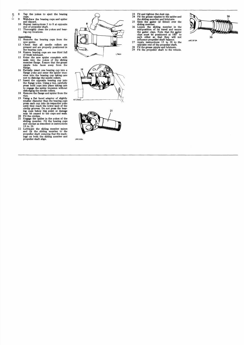
8/3/2019 LAND ROVER SIII_ROM_Part_4Fuel Cont Exhaust, Coolant and Clutch and Gearbox
http://slidepdf.com/reader/full/land-rover-siiirompart4fuel-cont-exhaust-coolant-and-clutch-and-gearbox 41/50
PROPELLER SHAFT
Removeand refit
Front propeller shaftRearpropeller shaft
47.15.0247.15.03
Removing1 Disconnect the propeller shaft from
the axle andgearbox.2 Withdrawthe propeller shaft.
Refitting3 Locate the propeller shaft in position
ensuring that the sliding member isfitted towards the front of the vehicle.
4 Fit the securingnuts and bolts to theaxle and gearbox flanges. Torque 4,2to 5,2kgf. m (30 to 38 lbf. ft. )
PROPELLER SHAFT
Overhaul
Front propeller shaftRear propeller shaft
47.15.1147.15.12
3
2RC632A
Dismantling1 Remove the propeller shaft from the
vehicle.2 If a gaiter encloses the slidingmember
release the two securing clips. Slidethegaiter along the shaft to expose theslidingmember.
3 Note the alignment markings on thesliding member and the propellershaft.
4 Unscrew the dust cap and withdrawthe slidingmember.
5 Clean and examine the splines forwear. Wom splines or excessive back-lash will necessitate propeller shaftrenewal.
6 Remove paint, rust, etc. from thevicinity of the universal joint bearingcups and circlips.
7 Remove the circlips, and greasenipple.
continued
2RC635A

8/3/2019 LAND ROVER SIII_ROM_Part_4Fuel Cont Exhaust, Coolant and Clutch and Gearbox
http://slidepdf.com/reader/full/land-rover-siiirompart4fuel-cont-exhaust-coolant-and-clutch-and-gearbox 42/50
" "8 Tap the yokes to eject the bearing 23
-..J
I cups. 24tv 9 Withdraw the bearing cups and spider
and discard. 2510 Repeat instructions 5 to 8 at opposite
end of propeller shaft. 2611 Thoroughly clean the yokes and bear-
ing cup locations.
Assembling12 Remove the bearing cups from the
new spider.
13 Check that all needle rollers arepresent and are proper ly positioned inthe bearing cups.
14 Ensure bearing cups are one third fullof fresh lubricant.
15 Enter the new spider complete withseals into the yokes of the slidingmember f lange. Ensure that the greasenipple hole faces away from theflange.
16 Part ially inse rt one bearing cup into af lange yoke and enter the spider trun-nion into the bearing cup taking carenot to dislodge the needle rollers.
17 Inse rt the opposite bearing cup intothe flange yoke. Using a vice, carefullypress both cups into place taking careto engage the spider trunnion withoutdislodging the needle rollers.
18 Remove the flange and spider from thevice.
19 Using a flat faced adaptor of slightlysmaller diameter than the bearing cupspress each cup into its respective yokeunt il they reach the lower land of thecircl ip grooves. Do not press the bear-ing cups below this point or damagemay be caused to the cups and seals.
20 Fit the circl ips.21 Engage the spider in the yokes of the
sl iding member. Fit the bearing cupsand circlips as described in instructions15 to 20.
22 Lubricate the sliding member spinesand fit the sliding member to thepropeller shaft ensuring that the mark-ings on both the sliding member andpropeller shaft align. 2RC638A
Fit and tighten the dust cap.Fit the grease nipples to the spider andthe sliding member and lubricate.Slide the gaiter (if fitted) over thesliding member.Locate the sliding member in themid-posit ion of its travel and securethe gaiter clips. Note that the wterclips must be positioned at 180 toeach other so that they will notinfluence propeller shaft balance.
27 Apply instructions 15 to 20 to the
opposite end of the propeller shaft.28 Fit the grease nipple and lubricate.29 Fit the propeller shaft to the vehicle.
26
4RC873A

8/3/2019 LAND ROVER SIII_ROM_Part_4Fuel Cont Exhaust, Coolant and Clutch and Gearbox
http://slidepdf.com/reader/full/land-rover-siiirompart4fuel-cont-exhaust-coolant-and-clutch-and-gearbox 43/50
HALF SHAFT (88 models)
Remove and refit 51.10.01
Removing1 Jack up the rear of the vehicle and
support securely.2 Remove the road wheels.3 Rotate and slide off the hub cap.4 Remove the split pin and nut securing
the half shaft to the driving flange.
5 Remove the washer and seal.6 Remove the bolts and washers securingthe driving f lange to the hub.
7 Withdraw the ha lf shaft complete withdriving flange and gasket.
8 Remove the driving flange from thehalf shaft.
Refitting9 Reverse instructions 1 t o 8.10 Torque: Half shaft nut. 1,4 to 2,0 kgf.
m (10 to 15 l bf. ft.)Drive flange bolt. 4,2 to 5,2kgf. m (30 to 38 lbf. ft.)
HALF SHAFT (109 models)
Remove and refit 51.10.01
Removing1 Jack up the rear of the vehicle and
support securely.2 Remove the road wheel.3 Rotate and s lide off the hub cap.4 Remove the bolts and spr ing washers
secur ing the driving flange to the hub.5 Withdraw the driving flange and half
shaft and gasket.6 Remove the c irclip from the half shaft .7 Withdraw the driving flange.8 Remove the '0' ring.
Refittill89 Reverse instructions 1 t o 8
Torque : Drive flange bolts 4,2 to 5,2kgf. m (30 to 38 lbf. ft.)
HUB BEARINGS
Remove and refit 51.10.28
25 Fit the half shaft and driving flangeassembly.Torque the bolts to 4,2 to 5,2 kgf. m(30 to 38 Ibf. ft.)
·26 Fi t the brake drum and road wheel .27 Lower the vehicle .
Removing1 Jack up the rear of the vehicle and
support securely.2 Remove the road wheels.3 Remove the bolts and spring washers
securing the driving flange to the hub.4 Withdraw the driving flange and half
shaft.5 Remove the brake drum retainingscrews and withdraw the brake drum.
6 Straighten the tabs on the hub nutlock washer.
7 Unscrew and remove the locknut .8 Remove the lock washer, adjusting nut
and thrust washer.9 Withdraw the hub complete with bear-
ings and oil seal.10 Remove the outer bearing.11 Remove the oil seal and inner bearing.12 Remove the outer and inner bearing
tracks from the hub.13 Thoroughly clean all components.
Refitting
14 Fit the outer and inner bearing tracksto the hub.
15 Pack the hub with fresh grease.16 Insert the inner bearing in the hub.17 Fit new oil seal to the hub. Lips of seal
towards the inner bearing.18 Insert the outer bearing on the hub
and slide hub and bearings into posi-tion on the stub axle.
19 Fit the thrust washer and adjustingnut.
20 Tighten the adjusting nut to obtainzero hub end-float.
21 Using a dial gauge to check end-floatslacken the adjus ting nut sufficient toobtain end-float of 0,05 to 0,10 mm
(0.002 to 0.004 in. ).22 Fit the lock washer and lock nut.
Tighten the locknut.23 Bend the lock washer to secure the
adjust ing nut and lock nut.24 Fi t a new driving flange gaske t.

8/3/2019 LAND ROVER SIII_ROM_Part_4Fuel Cont Exhaust, Coolant and Clutch and Gearbox
http://slidepdf.com/reader/full/land-rover-siiirompart4fuel-cont-exhaust-coolant-and-clutch-and-gearbox 44/50
V>-IN
DIFFERENTIAL ASSEMBLY(88 models)
Remo-re and refit 51.15.01
RemovingI Jack up the rear of the vehicle and
support on stands.2 Remove the road wheels.3 Drain the oil from the rear axle.4 Remove the bolts and spring washers
securing the hal f shaft fl anges to therear hubs.
5 Withdraw the half shafts and driveflanges.
6 Disconnect the propeller shaft at therear axle.
7 Remove the nuts and spring washerssecur ing the differential assembly tothe axle casing.
S Withdraw the differential assemblyand gasket
Refitting9 Reverse instructions I to S.
DIFFERENTIAL ASSEMBLY(Salisbury type 109 models)
Remo ve a nd r ef it
Overhaul
Service tools:
47ISG l31 CISG 191
ISG 1122ISG 1205S 123AISG47 BK
ISG47 BL18G 1122GISG 134DPISG 191P18G l31 FRO 1008530106
51.15.01
51.15.07
Screw pressAxle spreaderDial gauge, bracket and base
Screw pressSpanner fordrive couplingPinion bearing cup removerPinion bearing coneremover/replacerDifferential bearing removerPinion bearing cup replacerDifferential bearing replacerSetting gauge forpinion heightPegs for axle spreaderOil seal replacerDial gauge bracket
Remo vi ng t he d if fe re nt ia l u ni t
NOTE: All fixingbolts used on the differentialassembly and differential cover have metric
threads.I Drain offthe differential lubricating oil.2 Removethe rear axleassembly. 51.25.01.3 Removethe hub driving member fixings.
4 Withdraw the driving member andattached axle shaft sufficientto disengagethe differential.Repeat 4 for other axle shaft.Remove the fixings and support strip atthe differential cover and withdraw thecover and joint washer.
9 Clean out and examine the spreader toolpegholesprovided in the gear casing face;ensure that theholesare free fromdirt andburrs and damage.
10 Ensure that the turnbuckle adjuster isfreeto turn.
II Fit the axle spreader to engage the pegholes. Spreader ISG 131C, Adaptor pegsISG 131 F.
12 Turn the adjuster until all free playbetween the spreader and casing is taken
up, denoted bythe adjuster becoming stiffto turn, using a spanner on the adjuster.13 Check that the side members of the
spreader are clear of the casing.14 Stretch the casing, rotat ing the adjuster
byone flatat a time, until the differentialassembly can be leveredout. Do not leveragainst the spreader; use suitable packingunder the levers to avoid damage to thecasing.
CAUTION: To prevent permanent dam-age to the gear carrier case, it must not beover-stretched. Each flat on the turn-buckle i s numbered to enable a checkto be made on the amount turned. Themaximum stretch permitted is 0,30 mm
(0.012 in), equivalent to three fiats.15 Ease off the adjuster and remove the
spreader.
continued
5
6
6
IRC198A
7 Note the re lationship marking on thebearing caps and axle cas ing to ensurecorrect refitting.Remove the fixings and withdraw the dif-ferential bearing caps.
S

8/3/2019 LAND ROVER SIII_ROM_Part_4Fuel Cont Exhaust, Coolant and Clutch and Gearbox
http://slidepdf.com/reader/full/land-rover-siiirompart4fuel-cont-exhaust-coolant-and-clutch-and-gearbox 45/50
D i sm an t l in g t b e d i tj " er e n ti a l u n i t16 Add alignment marks between the crown
wheel and the differential case for reas-semblypurposes, then remove the fixingsand withdraw the crown wheel.
lRC484
16
17 Note the alignment markings on the two
differential casings to ensure correct refit-ting, thenremove the fixings.18 Lift offthe upper case.
Iw
19 Withdraw the upper differential wheeland thrust washer.
20 Liftout the cross-shaft and pinions.
21 Withdraw the dished thrust washers.
22 Withdraw the lowerdifferential wheelandthrust washer.
23 Remove the differential bearing cones .Remover 18G47 BL details I and 2,Press47.
24 Withdraw the shim washers fittedbetween the bearing conesand the differ-ential casings.
R em o vi ng t be f in al d ri ve p in io n25 Prevent the coupling flange from rotating
and remove the flange locknut and plain
washer. Spanner 18G 1205.26 Support the drive pinion and remove the
coupling f lange by tapping with a hidehammer.
27 Withdraw the drive pinion together withthe inner bearing cone.
28 Withdraw and discard the collapsiblebearing spacer.
29 Withdraw the oil seal, gasket and oilthrower.
30 Withdraw the outer bearing cone.
31 Extract the pinion inner bearing cup andshim washers from the casing. Note theshimwasher thickness. Remover S 123A.
32 Extract the pinionouter bearing cup fromthe casing. RemoverS 123A.
33 Remove the inner bearing cone from thepinion. Remover 18G47 BKand Press 47.
continued

8/3/2019 LAND ROVER SIII_ROM_Part_4Fuel Cont Exhaust, Coolant and Clutch and Gearbox
http://slidepdf.com/reader/full/land-rover-siiirompart4fuel-cont-exhaust-coolant-and-clutch-and-gearbox 46/50
U Inspecting 42 Fit the crown wheel to the different ial 49 Move the differential unit fully toone side-1 34 Examine all components for obviouswear casing. Fixings torque is 15,3 to 17,3 ofthe casing; do not tilt the unit.
or damage. kfrum (111 to 125 Ibf ft). Use Loctite 50 Rotate the differential unit to settle the35 The bearing cones must be a press fit o n ' tudlock' grade CVX on the fixing bolt bearings, continue to lever the differential
their locations, except the drive pinion threads. to the side, then zero the dial gaugeflangeand bearing which isa slide fit. 43 Press on the differential roller bearing indicator.
36 The crown wheel and pinion are supplied cones less shim washers, using 18G 134 51 Lever the assembly fully to the other sideasa matched pair and must not be inter- DP, and leave tooneside until required for ofthe casing, rotate the unit to settle thechanged separately. instruction 87. bearings, then note the total indicatorA new crown wheel and pinion matched 44 Fit the bearing cups to the differential. reading.pair may be fitted to an original gear car- 45 Fit the differential unit and bearings tothe 52 Add 0,127 mm (0.005 in) , for bearingrier casing if sound. The original crown gear carrier casing, and rotate unit to cen- pre-load, to the total noted in the preced-
wheel and pinion, if sound, may be fitted tralize the bearings. Donot fit the bearing ing item. The sum is then equa l to theintoa replacement casing. caps. nominal value of shims required for the
37 The two parts of the differential unit cas- 46 Position a suitable dialgauge indicator on differential bearings.ingare matched and must not be replaced the casing with the stylus registering on Shims are available in the range 0,07 mmseparately. the back face ofthe crown wheel. (0.003 in), 0,12 mm (0.005 in), 0,25 mm
38 Discard and renew all thrust washers. (0.010 in) and 0,76 mm (0.030 in). Select39 Differential housings with worn thrust the total value of shims required.
washer seatings must be replaced as a pair. 53 Remove the differential unit and bearings40 Examine the differential case to crown and place aside. Do not fit the shim
wheel joint face for burrs and damage washers until the subsequent 'Differentialwhichcould lead to crown wheel run-out backlash' checks have been made, itemswhen fitted. 87 t093.
Reassembling
A ss em b l in g t he d i ff er en t ia l u n it
41 Reverse the i tems 17 to 22 a ligning themarks onthe differential casings. Casingsfixingstorque load is9,1to 10,4kgfm (66to 75 Ibfft). The fixings tightening shouldbecarried out at opposite sides ofthe cas-ings and not by following the diameter.Use Loctite'Studlock' grade onthe fixingbolt threads.
F it ti ng d r iv e p i ni on54 Select shim washers ofthe samethickness
value as those removed from under the
pinioninner cup, item 31, and place readyfor fitting.
47 Rotate the differential and check the totalindicated run-out onthe crown wheel backface. This must not exceed 0,05 mm(0.002 in). If run-out is excessive, checkthe mating faces for dirt and damage; ifnecessary. select a new radial position forthe crown wheel. When satisfactory. con-tinue with the followingcheck.
D if fe re n ti al b e ar in g a d ju s tm e n t48 Inser t two leversbetween the casing and
the differential unit at one side.
55 Position the outer bearing replacer 18G1122G detail 2.and theouter bearing cuponthe press tool 18G 1122.
56 Locate the assembly intothe pinionhous-ingnose.
57 Placethe selectedshim washers on totheinner bearing cup seating.
58 Position the inner bearing cup in thecasing.
59 Position the inner bear ing replacer 18G1122G detail 1.onto 18G 1122and securewith the fixingnut.
60 Hold still the centre sc rew and turn thebutterfly leverto draw inthe bearing cups.
continued

8/3/2019 LAND ROVER SIII_ROM_Part_4Fuel Cont Exhaust, Coolant and Clutch and Gearbox
http://slidepdf.com/reader/full/land-rover-siiirompart4fuel-cont-exhaust-coolant-and-clutch-and-gearbox 47/50
61 Pressthe inner bearing coneontothedrivepinion.18G47BK,details I and 2and 47.
62 Posi tion the pinion and bearing in thecasing; omit the collapsible spacer at thisstage.
63 Fit the outer bearing coneonto the pinion.64 Fit the coupling flange and plain washer
and looselyfit the flange nut.65 Tighten the coupling flange locknut suf-ficient to remove end-float from thepinion.
66 Rotate the pinion to settle the bearingsand slowly tighten the flange locknut.Whilst using a spring balance to obtain atorque resistance of 9,25 to 13,8kgf em(8to 12tbf in) to rotate the pinion.
V-V
Drivepinionmarkings67 Check that the ser ial number marked on
the pinion end face matches that markedon the crown wheel.
68 The markings onthe end faceadjacent tothe serial number are of no significanceduring servicing.
69 The figure marked on the end faceopposite to the serial number indicates, inthousandths ofan inch, the deviation from
nominal required to correct ly set thepinion. A pinion marked plus (+) must beset be low nominal, a minus (-) pinionmust be set above nominal. An unmarkedpinion must be set at nominal.
70 The nominal set ting dimension is repre-sented bythe setting gauge block 18G 191P,which isreferenced fromthe pinion endface to the bottom radius ofthe differen-tial bearing bore.
Drivepinionadjustment71 Ensure that the pinion end faceis free of
raised burrs around the etched markings.72 Remove the keep disc from the mag-
netized base ofdial gauge tool 18G 191.
73 Place the dial gauge and sett ing gauge18G 191 P on a flat surface and zero thedial gauge stylus on to the setting gauge18G 191 P.
74 Posit ion the dial gauge central ly on thepinion end face with the stylus registeringon the lowest point on one differentialbearing bore. Note the dial gauge devia-tion from the zeroed setting.
75 Repea t on the other bearing bore. Addtogether the readings, then halve the sumtoobtain the mean reading. Note whetherthe stylus has movedup ordownfrom thezeroed setting.
Example I
Reading obtained L.H. sideReading obtained R.H. side
Add+ 0.006- 0.003
= + 0.003
Divideby 2 = + ° i003 = + 0.0015 in
+0.006-0.003
Therefore subtract 0.0015 in from the shimthickness behind the pinion inner bearingtrack.
Example 2
Reading obtained L.H. sideReading obtained R.H. side
Add + 0.006 in- 0.008 in
= - 0.002 in
D· id b 2 - 0.002 .IVI e y = --2-= +0.001 10
76 a. Where the stylus has moved down,
the amount isequivalent to the thick-nessof shims that must be removedfrom under the pinion inner cup tobringthe piniondownto the nominalposition.
b. Where the stylus has moved up, theamount is equivalent to the addi-tional thickness of shims required tobring the pinion up to the nominalposition.
+ 0.006- 0.008
continued
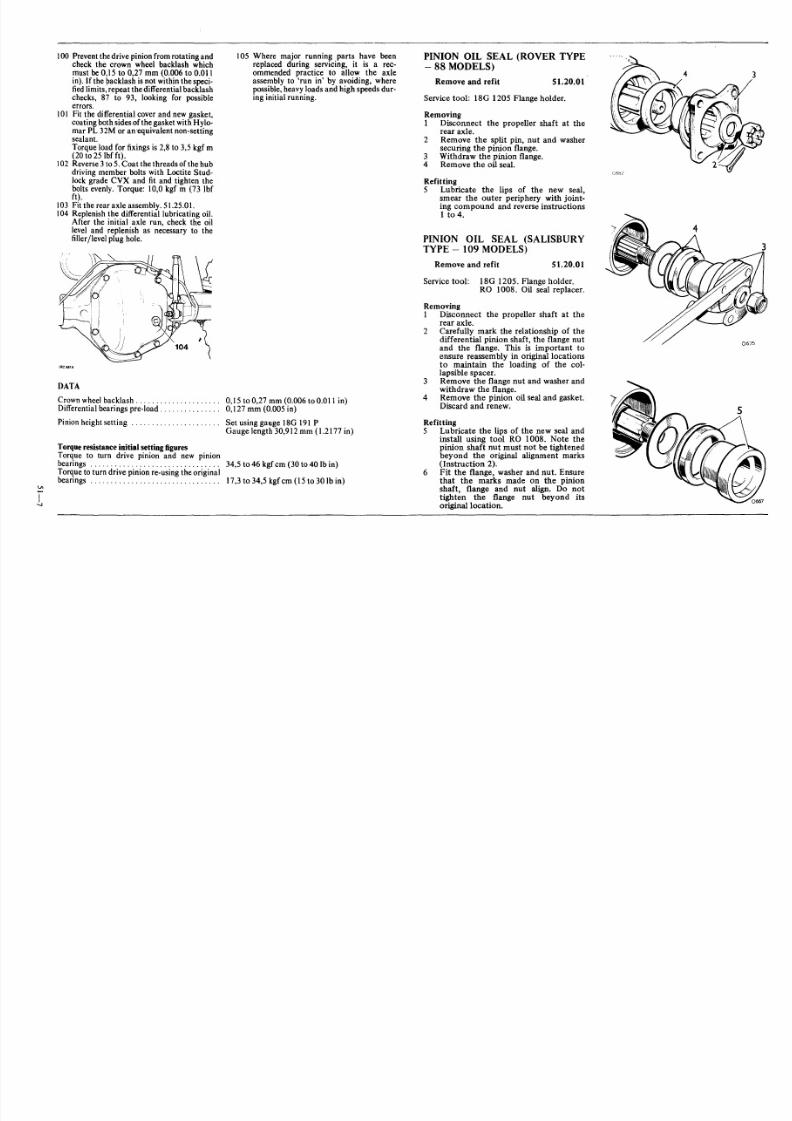
8/3/2019 LAND ROVER SIII_ROM_Part_4Fuel Cont Exhaust, Coolant and Clutch and Gearbox
http://slidepdf.com/reader/full/land-rover-siiirompart4fuel-cont-exhaust-coolant-and-clutch-and-gearbox 48/50
77 Before adjus ting the shim thickness , checkthe pin ion face marking and i f i t has a plus(+) f igure, subt ract that amount in thou-sands of inch f rom the shim thickness f ig-ure obtained in the previous item.Alternativ ely if th e pinion has a minus(-) figure, add the amount to the shimthickness figure.
M V 1 54
78 Adjust the shim thicknes s under the pin ioninner cup as necessary, by the amountdetermined ini t ems 76 and 77.
79 Recheck the pinion height setting 73 t o75.If t he set ting is cor rect , t he mean readingonthe dia l gauge wil l agree with the f iguremarked onthe pinion end face . For exam-
p le, with an end face mark ing of +3, thedial gauge reading should indicate that thepinion is0.003 in below nominal .
80 When the p inion setting is satisfacto ry,temporari ly remove the pinion outer bear-
ingcone.81 Fit a new collapsible bearing spacer,
f lared end outward , to the drive pin ion and
refit the outer bearing cone.82. Fi t the pin ion oil s linger.
83 Fit the oil seal gasket.84 Fit the pinion oil seal, lipped side first,
u sing general purpose grease or, wher eavailable, a molybdenum disulphide based
grease on the seal lip, using RO 1008 to
dri ft in the seal .85 Fit the coupling flange and plain washer
and loosely fit a new f lange nut. Secure18G 1205 to the coupling flange, using
slave fixings.
86 Alternately tighten the flange nut andcheck the drive pin ion resi st ance to rota-
tion until the following figures areachieved, as applicable:a. Assemb lies re-u sing origin al pinion
bearings: 17 ,3 to 34,5 kgf em ( 15 to30Ibfin).
b . Assemblies with new pinion bearings:34,5 to 46,0 kg f em (30 to 40 Ibf in) .
NOTE: A torque load of 34,5 kgf er n (250 Ibff t) approximate ly i s requi red on the coupl ing
flange nut to commence collapsing the bearing
spacer. Thereafter, torque resis tance build-upis rapid, theref ore check f requently, using aspring balance, toensure the correct figures arenot exceeded, otherwise a new collapsible bear-ing spacer will be required.
Differential backlasb cbecks87 Pick up the differential unit as left after
instruction 43.88 Fit the d if ferential unit and lever the un it
away from the drive pinion until theopposi te bea ring cup i s sea ted aga inst thehousing . Do not t ilt t he uni t.
89 Install a dial gauge on the casing with its
s ty lus resting on the back face ofthe crownwheel . Zero the gauge.
90 Lever the differential unit to engage thecrown wheel teeth in full mesh with thedrive pin ion teeth. Do not ti lt t he uni t.
91 Note the to tal reading ob tained on t he dialgauge.
92 From th is figu re subtract 0,25 mm (0.010in) to obtain the correct crown wheelbacklash when fit ted. The result indicatesthe value ofshimming to be fit ted betweenthe dif ferenti al case and the bearing coneat the crown wheel s ide of the differential.
93 Fit the shim value determined in 92,
t aking the shims from the pack previouslydete rmined dur ing 'Dif fe rent ia l bear ingad ju stment' checks, items 48 to 53. 18G
47 BL details 1 a nd 2, Press 47. 18G 134DP.
94 Fit the remaining shims from item 92 tothe opposite sid e of the d if ferential. 18G47 BL detai ls Iand 2, press 47. 18G 134DP.
95 Fit the differential unit with shims andbearings to the axle casing , using the axle
spreader 18G 131 C with pegs 18G 131 F.96 Remove the axle spreader.97 Fit the bearing caps in their correct pos -
i ti on , refer ring to the rel at ionship mark-ings on the caps and on the axle casing .
98 Tigh ten the bearing cap s fixing s to 12,9 to
14 ,5 kg m (93 to 1051b f t) .99 Mount a dial gauge on the ax le casing with
the s tylus res ting on a crown wheel tooth .
continued

8/3/2019 LAND ROVER SIII_ROM_Part_4Fuel Cont Exhaust, Coolant and Clutch and Gearbox
http://slidepdf.com/reader/full/land-rover-siiirompart4fuel-cont-exhaust-coolant-and-clutch-and-gearbox 49/50
100 Prevent thedrive pinionfromrotating andcheck the crown wheel backlash whichmust be 0,15 to 0,27 mm (0.006 to 0.011in). Ifthe backlash isnot withinthe speci-fiedlimits, repeat the differential backlashchecks , 87 to 93, looking for poss ibleerrors.
101 Fit the differential cover and new gasket,coatingbothsidesofthe gasketwith Hylo-mar PL 32M or anequivalent non-settingsealant.
Torque load for fixingsis 2,8 to 3,5 kgf m(20 to 25 Ibfft).
102 Reverse3to 5.Coat the threads ofthe hubdriving member bolts with Loctite Stud-lockgrade CVX and fit and tighten thebolts evenly.Torque: 10,0 kg f m (73 Ibfft).
103 Fitthe rear axle assembly. 51.25.01.104 Replenish the differential lubricating oil.
After the initial axle run, check the oillevel and replenish as necessary to thefiller/Ievel plug hole.
lRC581A
105 Where major running parts have beenreplaced during servic ing, i t i s a rec-ommended prac tice to al low the axleassembly to 'run in' by avoiding, wherepossible,heavy loads and high speeds dur-inginitial running.
DATA
Crownwheelbacklash. . . . . . . . . . . . . . . . . . . .. 0,15 to 0,27 mm(0.006 to0.011 in)Differentialbearings pre-load. . . . . . . . . . . . . . . 0 ,127 mm (0.005in)
Pinion height setting Set using gauge 18G 191PGauge length 30,912mm (1.2177 in)
Torque resistance initial setting figuresTorque to turn drive pinion and new pinionbearings 34,S to 46 kgf em (30 to 40 Ib in)Torqueto turn drive pinion re-using the originalbearings 17,3 to 34,5 kgf em (15 to 30 Ib in)
I-..I
PINION OIL SEAL (ROVER TYPE- 88 MODELS)
Remove and refit 51.20.01
Service tool: l8G 1205 Flange holder.
Removing1 Disconnect the propeller shaft at the
rear axle.2 Remove the split pin, nut and washer
securing the pinion flange.3 Withdraw the pinion flange.4 Remove the oil seal.
Refitting5 Lubricate the lips of the new seal,
smear the outer periphery with joint-ing compound and reverse instructions1 t o 4.
PINION OIL SEAL (SALISBURYTYPE - 109 MODELS)
Remove and refit 51.20.01
Service tool: 18G 1205. Flange holder.RO 1008. Oil seal replacer.
Removing1 Disconnect the propeller shaft at the
rear axle.2 Carefully mark the relationship of the
differential pinion shaft, the flange nutand the flange. This is important toensure reassembly in original locationsto maintain the loading of the col-lapsible spacer.
3 Remove the flange nut and washer andwithdraw the flange.
4 Remove the pinion oil seal and gasket.Discard and renew.
Refitting5 Lubricate the lips of the new seal and
install using tool RO 1008. Note thepinion shaf t nut must not be tightenedbeyond the original alignment marks(Instruction 2).
6 Fit the flange, washer and nut. Ensurethat the marks made on the pinionshaft, flange and nut align. Do nottighten the flange nut beyond itsoriginal location.

8/3/2019 LAND ROVER SIII_ROM_Part_4Fuel Cont Exhaust, Coolant and Clutch and Gearbox
http://slidepdf.com/reader/full/land-rover-siiirompart4fuel-cont-exhaust-coolant-and-clutch-and-gearbox 50/50
HUB OIL SEAL
Remove and refit 51.20.17
Asoperation 51.10.28 ins tructions 1 to 11.
REAR AXLE ASSEMBLY
Remove and refit 51.25.01
Removing
1 Slacken the rear road wheel nuts.2 Raise rear of vehicle and support thechassis securely on stands.
3 Remove the rear road wheels.
4 Disconnect the rear propeller shaftf rom the rear axle.
5 Raise the axle as required to releasethe axle check straps of all tension.Release one end of the check strapsfrom the chassis brackets.
6 88 inch chassis. Disconnect the lowerend of the shock absorbers from theroad spring bottom plates.
109 inch chassis. Disconnect the upperend of the shock absorbers from thechassis.
7 Slacken al l r ear shackle bolts.8 Lower the axle and allow its weight to
be supported on the road springs.9 Remove the 'D' bolts and spring
bottom plates.10 Disconnec t the brake pipe union from
the rear brake hose.11 Release the brake hose from the
chassis.
12 Seal the disconnected brake pipe andthe brake hose to prevent entry offoreign matter and loss of fluid.
13 Take the weight of the axle on thejack and with an assistant to steadythe axle remove the shackle bolts fromthe rear of the springs. Lower thesprings to the ground.
14 Withdraw the axle clear of the vehicle.15 109 inch chass is . Disconnect the lower
end of the shock absorbers from theaxle.
Refitting16 109 inch chassis. Fit the lower end of
the shock absorbers to the springbottom plate.
17 Using a jack and an assi stant loca te theaxle in its approximate pos it ion underthe vehicle.
18 Raise both rear springs and fi t the rearshacklebolts and nuts. DO NOTtighten the shackle bolts , f ront or rear,at this stage.
19 Lower the axle on top of the road
springs ensuring that the spring centrebolts properly engage the axle.20 Fit the 'D' bolts and spring bottom plates.
Evenly tighten the 'U'bolt nuts to 10,4kgfm (75 Ibf ft).
21 88 inch chassi s. Fit the lower end of theshock absorbers to the spring bot tomplates.109 inchchassis. Fit the upper end oftheshock absorbers to the chassis.
22 Fit the brake hose to the chassisensuring it is not twisted in the pro-cess.
23 Connect the brake pipe to the brakehose.
24 Secure the end of the check straps tothe chassis brackets.
25 Connec t the rear propelle r shaft to theaxle.
26 Adjus t the rear brakes asnecessary.27 Bleed the brakes. 70.25.02.28 Fit the road wheels.
29 Remove the chassis stands and lowerthe vehicle to the ground.30 Tighten all rear shackle bolts. Refer
64.20.01.31 Check axle oil level and top up as
required.