Land: Geology and Soilseisdocs.dsdip.qld.gov.au/Landsborough to Nambour Rail/EIS...5 Land: Geology...
16
5 Land: Geology and Soils 5 Environmental Impact Statement
-
Upload
hoangnguyet -
Category
Documents
-
view
216 -
download
0
Transcript of Land: Geology and Soilseisdocs.dsdip.qld.gov.au/Landsborough to Nambour Rail/EIS...5 Land: Geology...

5Land: Geology and Soils5
Environmental Impact Statement

Landsborough to Nambour Rail Project 148
5Introduction5.1
This chapter discusses the geology and soils of the project area and provides the following:
a description of the geology of the project area, including �surface and sub-surface materials and geological structures
identification of geological properties that may influence �ground stability, occupational health and safety, rehabilitation programs or the quality of wastewater leaving the site
discussion of the soils of the project area, with reference to �the properties which could influence land contamination, erosion potential, stormwater run-off quality, rehabilitation and agricultural productivity
discussion of the potential for land contamination from �existing and historical use, based on land use history and the nature and quantity of any contaminants.
This chapter of the EIS also provides information on potential impacts to soils and geology and proposed mitigation and management methods to be used for the project. Specific requirements for environmental management during construction and operation are discussed in Chapter 22, Environmental management plans. At this early stage of the project, it is not possible to determine all construction methods and sources, so this EIS discusses those issues where certainty is possible and provides a framework for future consideration and environmental management of construction activities with the potential to adversely impact on land and water resources through disturbance to soils and geological conditions.
Relevant legislation and policy 5.1.1 The following legislation and policy have been reviewed during the preparation of this chapter and are described in Chapter 1, Section 1.10:
State Planning Policy 1/92: Development and the �Conservation of Agricultural Land
State Planning Policy 2/02: Planning and Managing �Development Involving Acid Sulfate Soils
SPP 2/02 focuses on managing the potential adverse impacts on the environment and human health when undertaking activities such as excavation or filling in locations where ASS are known or likely to occur.
State Planning Policy 1/03: Mitigating the Adverse Impacts �of Flood, Bushfire and Landslide
State Planning Policy 2/07: Protection of Extractive Resources �
Environmental Protection Act �� and Environmental Protection Regulation 2008.
Methodology5.2
Review of existing information5.2.1 Various maps and drawings were used in undertaking the desk study for the site. These included geological maps, the Geological Survey of Queensland Sheet 9444 Nambour Special, Acid Sulfate Soils (ASS) risk maps, topography/survey data, Good Quality Agricultural Land Mapping (GQAL), preliminary scheme design drawings and aerial photographs amongst others. In many cases, this data has been viewed using the project GIS database which also included information pertaining to landslide hazard, land use and existing road maps.
No site investigation data is available for the existing rail alignment. However, a site investigation for the Northern Pipeline Interconnector was undertaken in 2007. This pipeline is generally located 2 km to the east of the project but is closer in some locations. Two geotechnical reports relating to this project have been made available, these are as follows:
1) Geotechnical Investigation Report for the Northern Pipeline Interconnector - TOC 5B, Landers Shute at Nobels Road, Mooloolah Valley to Noosa WTP, Bowlers Geotechnical, carried out for Southern Regional Water Pipeline (SRWP) Alliance.
2) Geotechnical Investigation Report for the Northern Pipeline Interconnector (NPI) – TOC 5A, from Nairn Road, Morayfield to Landers Shute at Nobels Road, Mooloolah, carried out for Southern Regional Water Pipeline (SRWP) Alliance.
Certain boreholes within these reports have been used to get an appreciation of the nature of the subsurface materials in the region. However, due to the distance from the project to many of these boreholes, they are not appropriate as a basis for detailed design. Therefore, a detailed geotechnical sampling strategy will need to be prepared to inform future stages of detailed design.
Desktop site investigation5.2.2 The site investigation carried out as part of this study comprised a desk study (followed by a two day site visit). The desk study entailed a review of public domain data and available aerial photography. It was undertaken in order to maximise the amount of data that could be gathered on site during the short timeframe available.
Aerial photograph interpretation5.2.3 Interpretation of stereo pairs of aerial photographs was carried out along the preferred route for the project prior to the site visit. The photographs were taken in June 2007 for the Department of Transport and Main Roads specifically for the project. These aerial photographs were of good quality and resolution.
The photos were reviewed by an engineering geologist to provide a means of identifying any geological and geomorphological hazards and to delineate the main engineering geological units interpreted to be present throughout the site area.

Environmental Impact Statement 149
Land: Geology and Soils5 5Site walk over survey5.2.4
A site walk over survey was undertaken by an engineering geologist on 13 and 14 October 2008. The purpose of this site visit was to:
locally ground truth the interpretation of the aerial photographs �
assess, where possible, the distribution and nature of various �geological materials and their engineering properties across the site
inspect the sites of tunnel portals, major cuttings, large �embankments, viaducts and other significant structures to identify any critical geotechnical issues.
The findings of the walk over survey were incorporated into the description of the engineering geological units and the engineering geological maps, presented as Figures 5.3a to e. Notably, the on-site observations demonstrated general agreement with the aerial photo interpretation.
Contaminated Land Database searches5.2.5 A search of the Environmental Management Register (EMR) and the Contaminated Land Register (CLR) has been undertaken for all directly affected properties along the project using real property descriptions. The information was supplied by the Department of Environment and Resource Management.
Limitations of study
The findings presented in this report are based on a review of regional geological data, aerial photographs and a brief site visit; as such, the information provided should be considered suitable for preliminary planning purposes only. Future ground investigations including boreholes and sampling shall be undertaken to inform the detailed design phase at a later stage of the project. The information provided in this chapter provides the basis for this future investigation.
Description of environmental conditions5.3
Desktop review 5.3.1
Geology
The 1:100,000 scale Nambour geological map sheet indicates that the project is underlain by the Triassic Landsborough sandstone. Where drainage channels occur, some areas of quaternary alluvium and colluvium are shown. The alluvium is typically associated with low lying, low relief, wetlands, while the sandstone is typically associated with moderate relief terrain with some higher relief ridges.
About 5 km to 10 km to the west of the project, is an area of volcanic terrain, comprising fine grained volcanic rocks such as basalt, andesite and dacite. This region is associated with high relief terrain and is the source area for most drainages occurring in the site area.
A regional geological map illustrating the distribution of the main geological units is presented as Figure 5.3a.
Alluvium
The alluvial material is described as clay, silt, sand, gravel flood plain alluvium. Considering the transient nature of alluvial deposition processes, considerable variability in terms of grain size, distribution and grading should be expected. The thickness of the alluvial material is likely to vary significantly, from less than one metre to greater than 10 metres.
This material is generally underlain by the Landsborough sandstone.
Colluvium
Some localised colluvium is mapped in the project area and is generally associated with the alluvium and lower lying areas at the base of slopes. It is described as residual deposits and pediment slope wash, clay scree and soil. As the colluvium occurs relatively low in the landscape, it is expected to comprise finer grained materials (sands/silts/clays).
This material is generally underlain by the Landsborough sandstone.
Landsborough sandstone
Two units of the Landsborough sandstone are present in the area, although they are both mapped as ‘Triassic / Jurassic – Landsborough sandstone’. They are anticipated to be very similar in terms of engineering properties. Both are essentially quartzose sandstone, but with distinctions based on varying amounts of secondary components, such as feldspar.
The sandstone unit occurring in the north, denoted as Rjbw, is described as late Triassic quartzose sandstone, siltstone, shale conglomerate and coal, while the unit occurring in the south, denoted as Rji, is described as late Triassic lithofeldspathic labile quartzose sandstone, siltstone, shale, minor coal. Based on these descriptions, the engineering properties of the two sandstones are likely to be primarily controlled by the degree of weathering that has occurred, a factor which will not necessarily correlate with the marginal changes in the sandstone composition noted. The amount of shales, siltstone and coal will greatly influence the engineering properties and depth of weathering. However, the distribution or proportion of these additional components within the Landsborough sandstone is not presented on existing maps.
Structure
The Landsborough sandstone in the site area is generally gently folded along north-west trending anticlines and synclines. The resulting bedding structures dip at about five to 15 to the north- east and south-west, although may be locally steeper. No major faults are mapped in the area, although it should be expected that some small scale faulting is associated with folding.
Land: Geology and Soils5
Landsborough to Nambour Rail Project 150
Acid sulfate soils (ASS)
Acid sulfate soils (ASS) are associated with low lying areas below 5m AHD, such as the alluvial plains where groundwater is generally close to the surface and where materials have generally been in reducing conditions. As such, the main risk zones are likely to be associated with the drainage features outlined in Chapter 14, Water resources and in the vicinity of wetlands, should they be disturbed.
A review of the ASS risk maps published by the Department of Environment and Resource Management notes that no risk zones are present to the south of Palmwoods; however, the alluvial plains associated with Petrie Creek and Paynter Creek are designated ASS risk zones.
Acid sulfate rock (ASR)
Acid sulphate rock (ASR) becomes an issue when sulphide bearing (commonly pyrite) lithologies are disturbed and weathered. The resulting oxidation releases weak acids which may be washed into the groundwater and represent a threat to the environment.
Pyrite and other sulphide bearing minerals are usually associated with sedimentary rocks deposited in reducing environments, such as shales and phyllites, but may also occur as a result of hydrothermal alteration of other rock types. As such, the Landsborough sandstone may contain minor amounts of pyrite within the thin bands of shale or within veins. However, due to the relatively minor quantities anticipated, the risk may be low but nevertheless requires consideration.
Coal beds noted within the Landsborough sandstone will contain significant amounts of sulphide minerals, and if encountered, will need to be managed.
Contaminated land
A search of the Department of Environment and Resource Management Environmental Management Register (EMR) and the Contaminated Land Register (CLR) was undertaken for properties subject to a land requirement for this project. This identified 25 lots on the EMR, 24 of which are sections of the existing rail corridor. The other lot identified (lot 301 M332061) is the Landsborough sports and recreational ground. It is understood that this site was historically used as cattle yards, and therefore is included on the EMR. No sites within the project area were found to be listed on the CLR at the time the searches were undertaken1.
Sites on the Department of Environment and Resource Management EMR are shown on Figure 3.2f in Chapter 3, Land use and infrastructure.
Good quality agricultural land (GQAL)
GQAL data was collated from Caloundra City Plan and Maroochy Plan (in which GQAL is called Agricultural Protection) and were used to identify the areas affected by the project. This is discussed in Chapter 3, Land use and infrastructure, Section 3.2.8, and shown Figure 3.2g.
1 Searches were completed 13 November 2008
Ground conditions5.3.2 Based on the desk study and site visit, the ground conditions, including the inferred stratigraphy, distribution of groundwater and the associated engineering geological units are described below.
Stratigraphy
The stratigraphy in the area generally comprises:
a thin layer of topsoil overlying �
a variable thickness of residual soil � 2 which overlies
variably weathered sandstone (Landsborough sandstone) �
topsoil underlain by a variable thickness of alluvium/ �colluvium in the vicinity of drainages.
These components of the stratigraphy are summarised in Table 5.3.2a.
Table 5.3.2a: Summary of the site stratigraphy
Depth Interval (m b.g.l*) Description
0.0m to 0.3m (or less) Top soil – sand, clay, organics
Ground surface to depths of between 1m and 10m (approximately)
Residual soil (sand/clay), typically less than 3m thick
Alluvium (sand/clay/gravel), may be greater than 10m thick
Top of unit – 1m to 3m lower
Base of unit and to depths of between 10m and 15m
Extremely to distinctly weathered Landsborough sandstone, potentially some shale, mudstone and coal
Generally occurring at depths greater than 3m, but typically deeper
Slightly weathered Landsborough sandstone, potentially some shale, mudstone and coal
Topsoil
Based on information from test pits and boreholes remote from the site, the topsoil is likely to be about 0.1 metres to 0.3 metres thick and comprises sands, clays and organic matter.
Alluvium
The maximum thickness of the alluvium in the project area is unknown, as borehole investigations have not been undertaken at this stage. However, boreholes to the north of Nambour (near Petrie Creek) show the alluvium to be approximately 10 metres thick. In general, the thickness of the alluvium will vary considerably, depending on what section of the landscape is assessed and the extent of the drainage system.
As noted in Section 5.3.1, the composition of the alluvium varies. For instance, at Petrie Creek to the north of Nambour, the alluvial sequence noted in Table 5.3.2b was encountered.
2 a soil derived from the in situ weathering and decomposition of rock
Environmental Impact Statement 151
Land: Geology and Soils5 5Table 5.3.2b: Alluvial stratigraphy (from nearby borehole)
Depth Interval (m b.g.l)*
Description
0-0.2m Clayey silty sand (SC) (thin topsoil cover)
0.2-3.5m Silty sand (SM), very loose
3.5-4.6m Clayey silty sand (SM/SC), very loose to loose
4.6-4.9m Silty clay (CL/CI), soft to firm
4.9-5.5m Clayey silty sand (SM/SC), very loose to loose
5.5-8.0m Clayey sand (SC), very loose
8.0-10.2m Sand (SP), loose
*m b.g.l – metres below ground level
As suggested by Table 5.3.2b, the highly variable normally consolidated sediments are likely to have engineering implications in terms of foundation performance. Notably, variability of this type may be expected horizontally as well as vertically.
The boundary between the alluvium and underlying residual soils is best defined on the basis of strength, with the residual material behaving as an over consolidated material. Significant amounts of gravel are also noted within the alluvium.
Residual soil
The thickness of residual soil varies from approximately 0.3 metres to approximately two metres, as noted from observations made at existing cuttings during the site visit. However, in lower relief areas the residual soil may be in excess of three metres thick. Some typical descriptions of the residual soil, as noted within existing boreholes and during the site visit, are as follows:
Clayey Sand (SC), fine to medium grained, red to brown, �often mottled, medium dense to dense (increasing with depth), poorly to well graded, low to medium plasticity fines
Sandy Clay (CI-CH), medium to high plasticity, mottled grey/ �brown, firm to very stiff (increasing with depth), often with some silt.
The boundary between the residual soil and the underlying bedrock is typically gradational and highly irregular.
Although not mapped, a thin covering of colluvial3 material may be present locally, although it may be indistinct from the upper areas of the residual soil due to the short distance over which the materials have been transported.
Landsborough sandstone
The Landsborough sandstone is likely to underlie the entire project area.
The properties of the sandstone typically vary with depth and the degree of weathering. In the upper areas of the weathered profile, the sandstone is typically extremely to distinctly weathered, fractured, bedded and very low to medium strength.
3 Transported slope deposited sediments, generally gravity driven
However, with increasing depth, the material becomes distinctly weathered to slightly weathered (eventually fresh), massive and medium to high strength.
The depth of the weathered profile varies considerably across the site. However, in the absence of boreholes and test pits an estimate of the depth of weathering has been made through aerial photograph interpretation and localised site observations. On this basis, the sandstone has been divided into two distinct engineering geological units, as discussed in Section 5.3.3.
Additional components to the Landsborough sandstone, such as shales and coal, were not seen during the site walk over. However, considering such materials are very susceptible to weathering, they would not intuitively be expected to outcrop in cuttings or on hill sides. The occurrence of shale, siltstone and coal seams has been noted within boreholes in the region, although generally at depths in excess of 10 metres. This suggests that the variability in relief may reflect the amount of shale/mudstone in the underlying geology.
Groundwater
Groundwater is considered to be a geological property that may influence ground stability, occupational health and safety, rehabilitation programs and potentially the quality of wastewater leaving areas of disturbance. Groundwater resources are discussed in Chapter 14, Water resources, Sections 14.3.2 and 14.5.3.
Engineering geological units 5.3.3 Following a review of aerial photography, the regional published geological data and site observation data, three engineering geological units have been identified and mapped.
The term engineering geological unit describes a group of material types that are interpreted to have similar engineering properties or similar ground profiles. The aim of translating geological boundaries into a separate set of engineering geological boundaries is to provide a more logical basis for the incorporation of geological information into design and project planning.
Generally, the engineering geological units are related to bedrock and topography. Additional factors, not illustrated on the geological map, which may be controlling the engineering properties of the ground, are:
structure (namely faulting/degree of fracturing) �
degree of alteration (as a result of the ancient regional �volcanism)
the amount of shale/siltstone interbeds. �
The engineering geological units identified in the project area are indicated on Figures 5.3b - e and discussed in Table 5.3.3.

Landsborough to Nambour Rail Project 152
Figu
re 5
.3a:
Geo
logy
DALES ROAD
MC
GIL
CH
RIS
TS R
OA
D
PASKINS ROAD
COES CREEK ROAD
WIN
DS
OR
RO
AD
MC
KEE
S R
OA
D
PRIN
GL
E R
OA
D
CARTER R
OAD
OLD PALMWOODS ROAD
WO
OM
BYE
PALM
WOODS R
OAD
TAINTONS ROAD
MENARY RO
AD
PINE GROVE R
OAD
OLD
BO
WLI
NG
GR
EE
N R
OAD
MU
LLE
RS
RO
AD
NAMBOUR CONNECTION ROAD
REDMONDS RO
AD
ATKI
NS
ON
S R
OAD
LANDERSHUTE ROAD
HOSPITAL R
OAD
OLD CHEVALLUM ROADBATT ROAD
CORLIS AVE
EUDLO ROAD
EUD
LO
WO
OM
BYE
NA
MB
OU
R
PALM
WO
OD
S
PAYN
TER
CR
EEK
PETRIE CRE
EK
EUDLO
CR
EEK
Figu
re N
o
Fig.
5.3
a S
cale
at A
3
Dra
win
g Ti
tle
Job
Titl
e
00.
250.
50.
751
Kilo
met
res
Z:\BNE\Projects2\86000\86618\GIS\Workspaces\2_EIS_Prelim_Design\EIS_Figures\Draft_6_090119\mxd\Fig_5-3a_Geology_D6_090119_A3.mxd
Dat
a so
urce
d fro
m th
e D
epar
tmen
t of T
rans
port
and
Mai
n R
oads
, and
the
Dep
artm
ent o
f En
viro
nmen
t and
Res
ourc
e M
anag
emen
t
1:30
,000
Lan
dsbo
roug
h to
Nam
bour
R
ail P
roje
ct -
EIS
Geo
logy
°
DALES ROAD
TUNNEL RIDGE ROAD
EUDLO ROAD
MC
GIL
CH
RIS
TS R
OA
D
DIAM
ON
D V
ALL
EY
RO
AD
WH
ITE
ROA
D
PASKINS ROAD
GAT
TER
A R
OA
D
OLD
GYM
PIE
RO
AD
KOW
AL
D ROAD
NO
BE
LS
ROAD
BEEC
H R
OADM
OO
LOO
LAH
CO
NN
EC
TI
ON
R
OA
D
VALLEY VIEW RISE
BR
AY R
OA
D
CORLIS AVE
EUDLO ROAD
EUD
LO
MO
OLO
OLA
H
LAN
DSB
OR
OU
GH
EUDLO
CR
EEK
MO
O
LOOLAH R
IVER
ADD
LIN
GTO
N C
REE
K
SOUTH
MOOLO
OLAH
RIV
ER
ME
L LU
M C
REE
K
!
! !
!
!
!
!
!
!
!
Bruce Highway
Nor
ther
nEx
tent
(rig
htw
indo
w)
Sout
hern
Exte
nt(le
ftw
indo
w)EU
DLO
BLI
BLI
TAN
AW
HA
WO
OM
BYE
NA
MB
OU
R
PALM
VIEW
MO
OLO
OLA
H
PALM
WO
OD
S
LAN
DSB
OR
OU
GH
Pref
erre
d R
oute
Cen
trelin
e
Exis
ting
Rai
l Lin
e
Stre
et
Cre
ek
Qa
- Qua
tern
ary
- Cla
y, s
ilt, s
and,
grav
el, f
lood
pla
in a
lluvi
um
Rjb
w -
Late
Tria
ssic
- Q
uartz
ose
sand
ston
e, s
iltst
one,
sha
leco
nglo
mer
ate,
coa
l
Rji
- Lat
e Tr
iass
ic -
Lith
ofel
dspa
thic
labi
le a
nd q
uarto
ze, s
iltst
one,
sha
le,
min
or c
oal,
ferru
gino
us o
olite
mar
ker
Rm
k/a
- Lat
e Tr
iass
ic -
Ande
site
flow
s an
d in
trusi
ves
Rm
p - L
ate
Tria
ssic
- R
hyol
itic
tuff
Tqr -
Ter
tiary
Qua
tern
ary
- Res
idua
lde
posi
ts a
nd p
edim
ent s
lope
was
h,cl
ay, s
cree
, soi
l
Tv -
Terti
ary
- Mai
nly
basa
lt flo
ws
Whi
lst e
very
car
e ha
s be
en ta
ken
to e
nsur
e th
e ac
cura
cy o
f thi
s da
ta, t
he D
epar
tmen
t of T
rans
port
and
Mai
n Ro
ads
mak
es n
o re
pres
enta
tions
or w
arra
ntie
s ab
out i
ts a
ccur
acy,
relia
bilit
y, c
ompl
eten
ess
or s
uita
bilit
y fo
r any
par
ticul
ar p
urpo
se a
nd d
iscl
aim
s al
l res
pons
ibili
ty a
nd a
ll lia
bilit
y (in
clud
ing
with
out
limita
tion,
liab
ility
in n
eglig
ence
) and
cos
ts w
hich
mig
ht b
e in
curre
d as
a re
sult
of th
e pl
an b
eing
inac
cura
te o
r inc
ompl
ete
in a
ny w
ay a
nd fo
r any
reas
on.

Landsborough to Nambour Rail Project 153
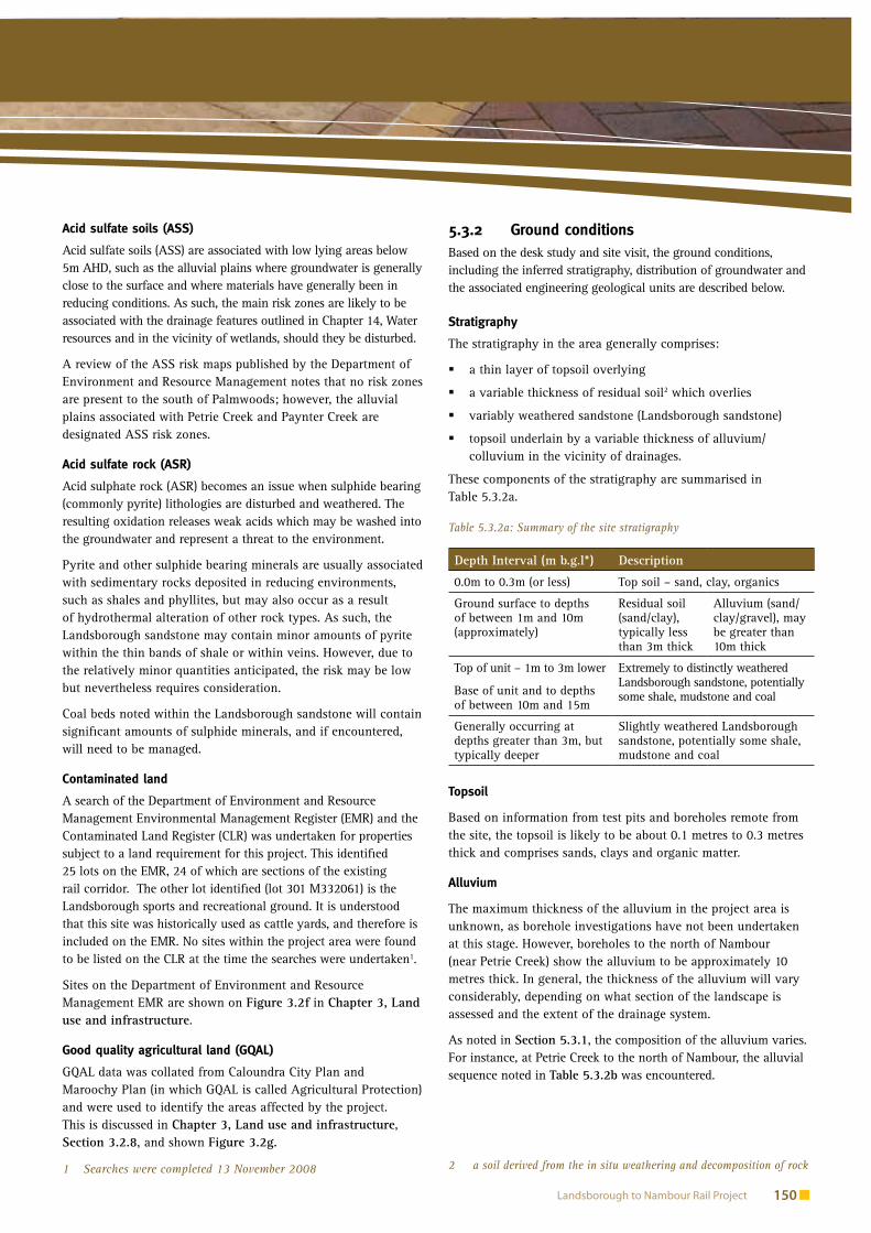
Figure 5.3b: Engineering Geological MapÜ
Ü
Î)
[[
[
[
[
[[ [[
[
[
[
[
[
[
[
[
[
[
[
[
[
[
[
[
[
[
[
[
[
[
[
[[
[[
[
[
[[
MOOLOOLAH
LANDSBOROUGH
C
C
A
B
A?
A?
B
BA
A C
C
C
B
B
B
??
15
2025-30
26Photograph 4
Photograph 1
Photograph 2
Photograph 3
GE14S + GE14N Types
14
Figure NoScale at A4
Drawing Title
Job Title
0 0.25 0.5 0.75 1
Kilometers
J:\8
6618
Lan
dsbo
roug
h to
Nam
bour
\L2N
_GIS
_Dat
a_P
acka
ge\m
xd\G
eolo
gy_F
ield
_Wor
k_A
JB_0
8111
7_2.
mxd
Legend[ Existing Boreholes
Î) Observation Location
á Dip Direction
Natural Slope Angle
"/ Dam - Agricultural
Ü Shallow Groundwater (Locally Marshy)
Ponding Surface Water
Drainage Channel
F Anticline (Based on AGS)
M Syncline (Based on AGS)
Approximate Boundary Between Units
V VΛ Λ! ! Ridge Line
Geological Units
A
B
C
Data sourced from Department of Transportand Main Roads, and the Department ofEnvironment and Resource Management.
1:20,000
Landsborough to Nambour Rail Project - EIS
Engineering Geological Map
°
Figure 5.3 b
4
Engineering Geological UnitsA: Normally consolidated soils ofconsiderably thickness (>2-3m), typicallyalluvial/colluvial clays, silts, sands andgravels, potentially very loose/soft, generallyassociated with a shallow or near surfacegroundwater
B: Shallow rock, generally extremely todistinctly weathered, typically low to mediumstrength within the uppermost 5 to 10 m,fractured, bedded, with a thin covering ofresidual soil (0-3m)
C: Shallow rock, generally distinctly toslightly weathered, medium to high strength,massive, bedded, with a thin covering ofresidual soil (0-1.5m)
Whilst every care has been taken to ensure the accuracy of this data, the Department of Transport and Main Roads makes no representations or warranties about its accuracy, reliability, completeness or suitability for any particular purpose and disclaims all responsibility and all liability (including without limitation, liability in negligence) and costs which might be incurred as a result of the plan being inaccurate or incomplete in any way and for any reason.

Environmental Impact Statement 154
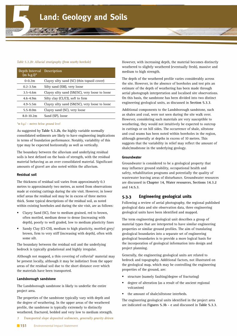
Land: Geology and Soils5 5Figure 5.3c: Engineering Geological Map
Ü
Ü
Ü
Ü
Ü
Ü
Î)
Î)
[
[
[[
[
[[
[
[
[
[
[
[[
[
[
[
[
[
[
[
[
[
[
[
[
[
[
[
[
[
[
[
[
[
[
[
[
[
[
[
[
[
[[[[[[
[[[[
[
[
[
[[
EUDLO
MOOLOOLAH
A
B
CC
C
C
A
A
B
C
C
C
C
A
B
A?
A?
B
BA
A C
C
C
25
1520
15
2025-30
26
4
Photograph 4
Photograph 1
Photograph 8
Photograph 7
Photograph 6
Photograph 5
GE2 Types (No planes) 2
15
Figure NoScale at A4
Drawing Title
Job Title
0 0.25 0.5 0.75 1
Kilometers
J:\8
6618
Lan
dsbo
roug
h to
Nam
bour
\L2N
_GIS
_Dat
a_P
acka
ge\m
xd\G
eolo
gy_F
ield
_Wor
k_A
JB_0
8111
7_2.
mxd
Legend[ Existing Boreholes
Î) Observation Location
á Dip Direction
Natural Slope Angle
"/ Dam - Agricultural
Ü Shallow Groundwater (Locally Marshy)
Ponding Surface Water
Drainage Channel
F Anticline (Based on AGS)
M Syncline (Based on AGS)
Approximate Boundary Between Units
V VΛ Λ! ! Ridge Line
Geological Units
A
B
C
Data sourced from Department of Transportand Main Roads, and the Department ofEnvironment and Resource Management.
1:20,000
Landsborough to Nambour Rail Project - EIS
Engineering Geological Map
°
Figure 5.3 c
4
Engineering Geological UnitsA: Normally consolidated soils ofconsiderably thickness (>2-3m), typicallyalluvial/colluvial clays, silts, sands andgravels, potentially very loose/soft, generallyassociated with a shallow or near surfacegroundwater
B: Shallow rock, generally extremely todistinctly weathered, typically low to mediumstrength within the uppermost 5 to 10 m,fractured, bedded, with a thin covering ofresidual soil (0-3m)
C: Shallow rock, generally distinctly toslightly weathered, medium to high strength,massive, bedded, with a thin covering ofresidual soil (0-1.5m)
Whilst every care has been taken to ensure the accuracy of this data, the Department of Transport and Main Roads makes no representations or warranties about its accuracy, reliability, completeness or suitability for any particular purpose and disclaims all responsibility and all liability (including without limitation, liability in negligence) and costs which might be incurred as a result of the plan being inaccurate or incomplete in any way and for any reason.

Land: Geology and Soils5
Landsborough to Nambour Rail Project 155
Figure 5.3d: Engineering Geological Map
Ü
Ü
"/
Î)
Î)
Î)
[
[
[
[
[
[
[
[[[[
[
[
[
[[
[
[
[
[
[
[
[
[
[
WOOMBYE
PALMWOODS
B
A
BA
A
B
A
B
B
A
B
CC
C
C
A
A
B
25
1520
Photograph 10
Photograph 6
Photograph 5
GE10 Types (No Planes)
7
1
10
Figure NoScale at A4
Drawing Title
Job Title
0 0.25 0.5 0.75 1
Kilometers
J:\8
6618
Lan
dsbo
roug
h to
Nam
bour
\L2N
_GIS
_Dat
a_P
acka
ge\m
xd\G
eolo
gy_F
ield
_Wor
k_A
JB_0
8111
7_2.
mxd
Legend[ Existing Boreholes
Î) Observation Location
á Dip Direction
Natural Slope Angle
"/ Dam - Agricultural
Ü Shallow Groundwater (Locally Marshy)
Ponding Surface Water
Drainage Channel
F Anticline (Based on AGS)
M Syncline (Based on AGS)
Approximate Boundary Between Units
V VΛ Λ! ! Ridge Line
Geological Units
A
B
C
Data sourced from Department of Transportand Main Roads, and the Department ofEnvironment and Resource Management.
1:20,000
Landsborough to Nambour Rail Project - EIS
Engineering Geological Map
°
Figure 5.3 d
4
Engineering Geological UnitsA: Normally consolidated soils ofconsiderably thickness (>2-3m), typicallyalluvial/colluvial clays, silts, sands andgravels, potentially very loose/soft, generallyassociated with a shallow or near surfacegroundwater
B: Shallow rock, generally extremely todistinctly weathered, typically low to mediumstrength within the uppermost 5 to 10 m,fractured, bedded, with a thin covering ofresidual soil (0-3m)
C: Shallow rock, generally distinctly toslightly weathered, medium to high strength,massive, bedded, with a thin covering ofresidual soil (0-1.5m)
Whilst every care has been taken to ensure the accuracy of this data, the Department of Transport and Main Roads makes no representations or warranties about its accuracy, reliability, completeness or suitability for any particular purpose and disclaims all responsibility and all liability (including without limitation, liability in negligence) and costs which might be incurred as a result of the plan being inaccurate or incomplete in any way and for any reason.

Environmental Impact Statement 156
Land: Geology and Soils5 5Figure 5.3e: Engineering Geological Map
Ü
Ü
Ü
Î)
Î)
[
[[
[
[[
[
[
[
[
[
[
[[
[
[
[
[
[
[
[[
[[
[[[[[
[[[[
[[[
[
[
[
[
[
[
[
[
[
[
[
[
[
[[[
WOOMBYE
NAMBOURA
B
A
A
B
B
A
B
A
BA
A
B
A
B
B
B
Photograph 13
Photograph 11
Photograph 12
Photograph 10
Photograph 9
GE10 Types (No Planes)
9
10 Figure NoScale at A4
Drawing Title
Job Title
0 0.25 0.5 0.75 1
Kilometers
J:\8
6618
Lan
dsbo
roug
h to
Nam
bour
\L2N
_GIS
_Dat
a_P
acka
ge\m
xd\G
eolo
gy_F
ield
_Wor
k_A
JB_0
8111
7_2.
mxd
Legend[ Existing Boreholes
Î) Observation Location
á Dip Direction
Natural Slope Angle
"/ Dam - Agricultural
Ü Shallow Groundwater (Locally Marshy)
Ponding Surface Water
Drainage Channel
F Anticline (Based on AGS)
M Syncline (Based on AGS)
Approximate Boundary Between Units
V VΛ Λ! ! Ridge Line
Geological Units
A
B
C
Data sourced from Department of Transportand Main Roads, and the Department ofEnvironment and Resource Management.
1:20,000
Landsborough to Nambour Rail Project - EIS
Engineering Geological Map
°
Figure 5.3 e
4
Engineering Geological UnitsA: Normally consolidated soils ofconsiderably thickness (>2-3m), typicallyalluvial/colluvial clays, silts, sands andgravels, potentially very loose/soft, generallyassociated with a shallow or near surfacegroundwater
B: Shallow rock, generally extremely todistinctly weathered, typically low to mediumstrength within the uppermost 5 to 10 m,fractured, bedded, with a thin covering ofresidual soil (0-3m)
C: Shallow rock, generally distinctly toslightly weathered, medium to high strength,massive, bedded, with a thin covering ofresidual soil (0-1.5m)
Whilst every care has been taken to ensure the accuracy of this data, the Department of Transport and Main Roads makes no representations or warranties about its accuracy, reliability, completeness or suitability for any particular purpose and disclaims all responsibility and all liability (including without limitation, liability in negligence) and costs which might be incurred as a result of the plan being inaccurate or incomplete in any way and for any reason.

Land: Geology and Soils5
Landsborough to Nambour Rail Project 157
Table 5.3.3: Engineering geological units
Engineering Geological unit Engineering Significance
Unit A: Unconsolidated soils of considerable thickness (>2-3m), typically alluvial and colluvial clays, silts, sands and gravels, potentially very loose or soft, generally associated with a shallow or near surface water table. Some alluvial material may be associated with elevated terraces at higher elevations.
poor performance as subgrade, especially when encountered in the vicinity of the water �table, potentially expansive and poorly drained
highly variable soil engineering properties �
generally unsuitable for use as any type of fill �
associated with poor foundation performance, with respect to settlement and allowable �bearing capacity
generally occurs in areas where the localised risk of flooding is present. �
Unit B: Shallow extremely to distinctly weathered sandstone rock, typically low to medium strength within the uppermost 5 to 10 m, fractured, bedded, overlain by residual soil (0-3m).
potentially suitable as general fill material, with the exception of the more clayey residual �soils in the upper 3m
relatively shallow cut slopes would be required within this material, except at depths of �greater than 10 m within less weathered material
likely to be rippable using appropriate earthmoving equipment �
moderate performance as a subgrade, although with poor drainage characteristics within �the residual soil, depending on the composition of the near surface materials
moderate performance as a shallow founding stratum for bridge and viaduct footings, �although subject to appropriate site preparation being adopted
low to medium erosion potential when exposed. �
Unit C: Shallow rock, generally distinctly to slightly weathered, medium to high strength, massive, bedded, with a thin residual soil covering (0-1.5m).
potentially suitable as general fill, subject to the appropriate breakdown of the larger �particles during excavation
optimal cut slopes within this material, subject to kinematic analysis, except for the upper �most 2 metres which would generally require cut back
potentially difficult excavation requiring large earthmoving equipment and/or blasting �
good performance as a subgrade material in this region, although with poor drainage �characteristics within the residual soil, depending on the composition of the near surface materials
good performance as a shallow founding stratum for bridge and viaduct footings, subject to �site preparation
low erosion potential when exposed. �
Assessment of potential design 5.4 and construction impacts and mitigation measures
Design considerations: acid sulphate 5.4.1 soils and rocks
As noted in Section 5.3.1, no risk zones have been identified to the south of Palmwoods, but the alluvial plains associated with Petrie Creek and Paynter Creek are designated ASS risk zones.
Therefore, a detailed ASS sampling and management regime will be implemented as part of the detailed design, geotechnical investigations and construction management planning. In particularly, areas around footings and bridge piers, or areas of excavation are the most at risk of disturbing ASS.
Sources of construction materials5.4.2 Construction material requirements would comprise:
general structural embankment fill �
sub-ballast capping �
ballast aggregate materials. �
Based on the limited data available, the following paragraphs outline areas where suitable materials may be found, although detailed geotechnical investigations would be required in order to confirm this. These guidelines are intended only for preliminary scheme design purposes and would need to be confirmed by investigation and testing during the detailed design stage of the project.
General fill
Material won from cuttings within engineering units B and C are likely to be suitable as general fill. However, the coarse fraction (cobbles and boulders) within the excavated material is likely to

Environmental Impact Statement 158
Land: Geology and Soils5 5be quite large (up to or greater than one metre), as such these materials may be restricted to use at depths of approximately one to two metres below formation level.
Shallow borrow sources, essentially the residual weathered material, are likely to be of marginal quality for use as fill, due to the high fines content. However, subject to the provision of adequate drainage and slope protection, it may be suitable.
Sub-ballast capping
In general, the materials excavated from cuttings are considered unlikely to be initially suitable for use as sub-ballast capping material. However, crushing of the materials (mainly unit B and unit C) could provide a source of sub-ballast material.
The naturally occurring near surface materials in the project area are considered unsuitable for use as sub-ballast capping.
Ballast aggregate
Ballast aggregate materials would most likely need to be sourced off-site as the locally won material is unlikely to be suitable. There are potential sources, comprising basalt and diorite, located to the west at a distance of approximately 5 km to 10 km. Based on the relief of the terrain in this area, the weathering profile may be shallow with suitable materials relatively close to the surface. However, it is expected that there may be environmental constraints in assessing these areas.
The Parklands blue metal resource reserve is located approximately 3 km the north of Nambour and may be utilised for construction, subject to the quantity of resource remaining at the time of construction. It may also be possible, subject to staging and decommissioning timeframes, to recycle and reuse ballast from the existing track.
Summary: Availability of construction materials
Site won material from engineering geological units B and C are likely to be suitable for general fill for use in embankments. However, there is likely to be a need to transport materials from where they are excavated to where they are needed to be placed as fill. This activity would need to be carefully managed.
The impacts on soil would be minimised, as soils will be stockpiled before earthworks take place for later use in landscaping.
Site won materials are unlikely to be suitable for track ballast and this material would likely need to be imported. The nearby Parklands blue metal reserve may be a potential source, and subject to staging of the project, it may be possible to recycle ballast from the existing railway, for use in some locations.
Transport and handling
Table 5.3.3 indicates that engineering geological units B and C are considered potentially suitable for use as fill material for the project. Given that significant quantities of these materials would be available from within the site, transport of these
materials within the area identified for the project would be optimal, however the terrain the project traverses prior to construction may make this unfeasible.
Nearby reserves for ballast aggregate have also been identified. Depending on the lifespan of these resources, these sources would be given priority.
Local roads are expected to be used for construction traffic and the movement of fill materials. The roads listed below are considered likely to be utilised for the supply of construction materials, such as ballast and fill, equipment and personnel involved in the construction process:
Bruce Highway �
Glass House Mountain Road �
Mooloolah Connection Road �
Eudlo Road �
Palmwoods Mooloolah Road �
Ilkley Road �
Chevallum Road �
Woombye Palmwoods Road �
Nambour Connection Road �
Kiel Mountain Road. �
Stock piles
Stock piles of general fill and top soils would need to be created. These stock piles would need to be protected to prevent erosion. Sediment protection would also need to be provided to prevent material entering water courses during rain events. These provisions are discussed in Chapter 22, Environmental management plans.
Cuttings5.4.3 There are approximately eight major cuttings occurring along the project (i.e. cuttings greater than 10 metres high along the centreline). These are summarised in Chapter 4, Topography. The majority of these cuttings occur in the southern portion of the project within the higher relief region. However, numerous cuttings of lower height occur in other areas of the project.
Excavatability
The excavatability of the materials encountered and ease of ripping is dependent on numerous construction and design related factors. However, as a general guide, the excavatability of the materials is expected to reduce considerably with depth, with the upper residual soils being relatively easily ripped while the deeper fresh sandstone possibly requiring blasting. The depth of the weathering profile is therefore a major influence on the excavatability, a factor which has crudely been approximated based on the aerial photo interpretation but would require detailed geotechnical investigations in order to accurately assess.

Land: Geology and Soils5
Landsborough to Nambour Rail Project 159
Batter angles
The following batter angles are considered appropriate for preliminary design purposes:
residual soil and extremely weathered rock: one vertical unit �for every two horizontal units (1V:2H) – a flatter slope
distinctly weathered to fresh sandstone: one vertical unit for �every one horizontal unit (1V:1H) – a steeper slope
shales, claystone, mudstones, coal: one vertical unit for every �2.5 horizontal units (1V:2H to 1V:2.5H) – a flatter slope.
In light of the ground conditions, the hinge point between these two batter angles may be approximated to vary greatly. However, on the basis of the engineering geological units noted, the hinge point within unit C may be between two metres and five metres below ground level, while the hinge point within unit B may be greater than five metres below ground level.
Where shales or mudstones are encountered, the batter angles would require considerably cut back, potentially to approximately 1V:2.5H, depending on the nature and orientation of the defects and degree of weathering.
A significant hazard in the sandstone cuttings is the potential for encountering thin shale bands. Such features may result in plane failure along relatively shallow slip planes. This would require consideration during detailed design.
Residual soils, shales, claystone, mudstone and coal are easily eroded materials and are likely to require surface protection.
Site preparation- cuttings
Prior to commencing earthworks, the top soil should be stripped and stockpiled for later use in any landscaping. The topsoil is expected to be approximately 0.1 metres to 0.3 metres thick.
Drainage channels would also be required at the top of the batter crests to prevent face erosion. For the purpose of optimising crest stability, it is recommended that the drainage berm/trench should be placed at least 4 metres from the batter crest.
Embankments5.4.4 A significant component of the proposed rail alignment is above the existing ground level. However, in most cases, when in excess of 10 metres of formation fill is required, viaducts have been chosen as an alternative to earth structures. In general, the exception to this is in the higher relief, and less populated areas, where embankments have been chosen, the most significant of which (those greater than five metres) are summarised Table 4.5.2 in Chapter 4, Topography.
Numerous embankments are proposed which are less than 5 metres in height, and which are founded on unit A, although these are not listed in Table 4.5.2.
Subgrade conditions
The most significant embankments, listed in Table 4.5.2, are located on the more favourable engineering geological units of unit B and unit C. In such circumstances, the subgrade is expected to be relatively good, with few settlement and bearing capacity related issues. However, at the low points between hills, even if denoted as unit B or unit C, there may be a certain amount of colluvial material which could have less favourable foundation performance. Notably, the drainage properties of the near surface materials of unit B and unit C are considered poor and may require drainage installation.
Additional embankments, particularly those which occurring on unit A, will have poor subgrade conditions. This anticipated poor performance is attributed to the presence of loose/soft material in the vicinity of shallow groundwater. In such circumstances, low design California Bearing Ratio (CBR) values should be expected and measures would be required to improve the drainage below the embankment. In some circumstances, rock fill may be used to improve the subgrade conditions.
Embankment batters
For preliminary design purposes, embankment batters of 1V:2.5H are recommended for the embankment fill, particularly where subgrade conditions are less than favourable (in the vicinity of unit A). These batter angles may be steepened following detailed geotechnical investigation and design verification. The long term stability of the slopes may be stabilised through the placement of vegetation, geotextile or additional soil stabilisation measures.
Site preparation - embankments
Due to the presence of soft soils (specifically around major creek lines), stripping of the top soil would be required in areas affected by unit A prior to the commencement of construction. Such materials should be stockpiled for later use as landscaping.
Stripping or ‘box out’ of some near surface soft materials is expected to be nominally 0.1 metres to 0.3 metres; however, there is not adequate information to determine the exact amount of material that will need to be removed. These would be replaced with appropriate fill materials (sub-base) in order to improve the foundation conditions. Areas where this occurs will need to be allowed to settle over the construction period so that problems with tracks shifting are avoided at the operational stage.
Foundations for structures5.4.5 Viaducts and bridges are a significant component of the project. The foundations chosen for the various footings will depend on a number of factors, including the load imposed on each footing, the drainage characteristics of the ground, the height of the structure, the strength of the subsurface and compressibility/consolidation characteristics of the ground amongst other factors. In general, the following footing guidelines are recommended for preliminary design purposes:

Environmental Impact Statement 160
Land: Geology and Soils5 5Footings on unit A: Piled foundations are likely, largely due to the thickness of soft/loose material that has been noted in the alluvium and the presence of shallow groundwater.
Footings on units B and C: Shallow pad footings on residual soils are likely, nominally placed at depths of one metre to three metres deep depending on the depth of weathering. Where groundwater is shallow, weathering is very deep, or the proposed loads are large, then rock sockets or piles into more competent rock may be required.
Footings in the vicinity of active drainages would also require ‘scour’ to be incorporated into the design of footings, this is likely to necessary for pier footings at the various bridge sites.
The foundations and footings for structures would need to be designed in accordance with the mitigation measures outlined in Chapters 11, 12, 13, 14 and 21 for areas of environmental significance.
Tunnels5.4.6 A number of tunnels and cut and cover tunnels are proposed for the project. These are summarised in Table 5.4.6, and shown in Drawings C001 to C028:
Table 5.4.6: Tunnel descriptions
Tunnel location
chainage Drawing reference
Tunnel length and type
Rose Road, Mooloolah
85000 to 85420
C005 and C006
170m cut and cover, followed by 250m twin tunnels
The Pinch Lane, Eudlo
89230 to 89730
C010 and C011
140m cut and cover, followed by 310m twin tunnel, followed by 50 cut and cover
Eudlo School Road
91570 to 91700
C014 130m cut and cover, with reinstated Eudlo School Road over the top
North of Eudlo
92070 to 92300
C014 and C015
230m cut and cover, proposed to minimise the construction footprint (preferred to wider cutting)
Ground conditions at portals
The ground at all portals will be a function of the depth of cut in which they are placed. The deeper they are located in the weathering profile, the more competent the materials are likely to be. As the portals occur in unit C, the materials are likely to comprise distinctly weathered to slightly weathered sandstones, with local occurrences of residual soils at shallower depths. Rock defect orientations (ie cracks, fractures, joints) will determine stability in the more competent rock materials.
Preliminary kinematic analysis of rock defects information gathered near the Rose Road Tunnel (chainage 85000) is shown on Figure 5.3b.
Where batter angles in excess of those recommended in Section 5.4.2 are required, for example above portals, slope stabilisation measures are likely to be required. These measures are likely to comprise local rock bolts or possibly pattern bolting should weak, highly fractured materials be encountered. Under these circumstances, shotcrete and / or mesh may also be required.
Ground conditions – tunnels
Both tunnels should encounter distinctly to slightly weathered sandstones. Also, the massive nature of the sandstone, the steep natural slope angles and the generally shallow dipping bedding suggest that ground conditions may generally comprise a relatively good quality rock mass. It is not anticipated that the geology will pose a significant issue for the construction of the tunnels, provided that full ground investigations are undertaken and the engineering design is appropriate for the situation.
Groundwater is not expected to be encountered at invert level; however, perched water may be encountered following rainfall or during the winter months.
Excavation methods
Considering the relatively short length of the tunnels, the nature of the ground conditions and depth to the water table, construction of the tunnels may be best undertaken using a face shield with rock excavation achieved using a rock breaker or by drill and blast.
Temporary tunnel stabilisation measures are likely to be required and may comprise the installation or rock bolts, straps and mesh. Steel arches and/or shotcrete may also be required if bands of shale/mudstones are encountered.
A permanent lining may not be required due to the fact that groundwater is expected to be permanently deeper than invert level; however, for ensuring long term stability, a permanent lining may be favourable.
Potential operational impacts and 5.5 mitigation measures
The construction of the project is likely to have a number of impacts on the physical environment and these are described below. In the main, these impacts can be readily mitigated and managed during the design process, once detailed geotechnical investigations are completed.
Erosion of cuttings and embankments5.5.1 From observation, there appears to be little evidence of any significant erosion taking place on exposed soils and rock in existing cuttings. The detailed design phase of the

Land: Geology and Soils5
Landsborough to Nambour Rail Project 161
project however should be informed by future geotechnical investigations to prevent erosion taking place on cutting and embankments as a result of design decisions.
Typical measures that would be employed to prevent this impact are:
provision of drainage works above and on new slopes �
provision of erosion protection (either vegetation or shotcrete) �on exposed weak materials that are susceptible to erosion
application of sediment controls such as sediment fences, �retention basins, rock chutes etc
where possible, avoidance or minimisation of earthworks �during and shortly after periods of heavy rain and during windy conditions
avoiding works in sensitive locations in known wet periods �where possible
protection of temporarily exposed weak material. �
Acid sulfate soils and rocks5.5.2 As noted in Section 5.3.1, no risk zones have been identified to the south of Palmwoods, but the alluvial plains associated with Petrie Creek and Paynter Creek are designated ASS risk zones.
Therefore a detailed ASS sampling and management regime will be implemented as part of the detailed design, geotechnical investigations and construction management planning. In particularly, areas around footings and bridge piers or areas of excavation are the most at risk of disturbing ASS.
Potential for groundwater draw down5.5.3 Cutting and tunnels proposed for the project have the potential to draw down the natural ground water level. If this were to occur, it could have a negative impact on abstraction from existing ground water wells, on groundwater dependant ecosystems (GDE), springs and ground water dependant creek flows.
Further information about groundwater conditions and mitigation measures are included in Chapter 14, Water resources.
Water logging due to settlement of 5.5.4 embankments
Ground settlement resulting from the loading of soft soils under embankments can cause general settlement in the surrounding area. Where this intercepts a high ground water table, ponding can occur. This can also affect the natural drainage and prevent rain water moving toward natural and man made water courses. This potential impact needs to be carefully considered during the detailed design phase of the project with a particular focus on embankments and drainage measures.
Good quality agricultural land5.5.5 Impacts and mitigation measures relating to the conservation of GQAL are discussed in Chapter 3, Land use and infrastructure, Section 3.5.3.
Contaminated land: Potential impacts 5.6 and mitigation measures
A significant proportion of the existing rail corridor within the project area is listed in the Department of Environment and Resource Management EMR (but not the CLR). According to previous consultation with QR Limited, the potential contamination of the existing rail corridor is a result of the majority of the rail corridor being historically (1940s and 1950s) treated with the herbicide sodium arsenite, which was sprayed via boom arrangement onto the track. The resulting sodium arsenite has a low mobility and thus has a continued presence in the substrate. As a consequence, QR Limited has adopted a policy whereby all soils excavated for track work are treated as contaminated. Due to the mechanics of the spraying method used, most of the contamination occurs within five metres of the track formation, and to a depth of 0.5 metres. Beyond this, the levels are expected to be much lower. Subject to the proposed future use of the corridor, excavated material can generally be kept in the corridor either in the location of origin or within the near vicinity. The Queensland Department of Environment and Resource Management permit QR Limited to move excavated material by road, provided it is returned to the rail corridor (near the place of origin). Excavated material is to be kept away from watercourses and boundary fences, due to the potential for erosion to mobilise the contaminants in the soils.
Where the decommissioned sections of the existing railway are proposed for future uses, (i.e. within townships and for recreational trails), a sampling plan should be prepared to determine the extent of contamination and appropriate mitigation measures, if feasible.
Where construction of the project is in proximity to the existing rail corridor and requires excavation in or near the corridor, these areas should also be tested to determine the extent of contamination, and the need to remove contaminated soils. Measures to prevent the runoff from contaminated areas during construction are proposed in the environmental management plans contained in Chapter 22. In particular, ground waters and surface waters that leach or flow into any excavation of a contamination site will be contained (where possible) and monitored for water quality parameters.
At this early stage of the project, is it not feasible to conduct a preliminary site investigation in accordance with the Department of Environment and Resource Management draft guidelines for the assessment and management of contaminated land in Queensland 1998 and the National environmental protection (Assessment of site contamination) measures 1999. However, the sites identified in section 3.2.7 will form the basis of a schedule for investigation in accordance with these guidelines at a later stage of the project.

Environmental Impact Statement 162
Land: Geology and Soils5 5The project also has the potential to generate contaminated material from spills of hazardous substances. The environmental management plan will detail management measures for avoiding these impacts, mitigating the risk of impacts occurring and procedures for clean up in the event of a spill.
Summary and conclusions5.7
The potential geological issues arising in association with the project include:
the constructability of alluvium materials �
the constructability of tunnels �
the opportunity to reuse the materials from the cuts for �the embankments
the low potential for erosion �
the low potential for disturbing acid generating soils �and rocks.
Further investigations will be carried out to investigate the likelihood of these impacts to occur and determine the level of mitigation required during the detailed design phase (up to two years prior to the construction start).
This chapter has proposed strategies to mitigate the identified potential impacts. Table 5.7 outlines the potential impacts, mitigation strategies, and the significance of the residual impacts. It is important to note that the residual impacts identified are assessed on the basis of further investigations informing the development of detailed design and construction methods.
Due to the presence of soft soils (specifically around major creek lines), stripping of the top soil would be required in areas affected by unit A prior to the commencement of construction. Such materials should be stockpiled for later use as landscaping.
Stripping or ‘box out’ of some near surface soft materials is expected to be nominally 0.1 metres to 0.3 metres. However, there is not adequate information to determine the exact amount of material that will need to be removed. These would be replaced with appropriate fill materials (sub-base) in order to improve the foundation conditions. Areas where this occurs will need to be allowed to settle over the construction period so that problems with tracks shifting are avoided at the operational stage.
Table 5.7: Summary of impacts and mitigation (geology and soils)
Potential Impact Mitigation Strategy Residual Impact Significance
Constructability of alluvium detailed ground investigations to understand depth and extent of �alluvium material
appropriate site preparation for embankment, i.e. stripping or �‘box out’
appropriate use of footings for structure. �
Negligible
Constructability of tunnels detailed ground investigations to understand the ground �conditions at the tunnel locations
appropriate engineering to suit ground conditions. �
Negligible
Materials from the cuts opportunity to reuse for embankments (particularly engineering �geology units B and C)
Beneficial
Erosion of stockpiles and earthworks
provision of drainage works above and on new slopes �
provision of surface protection (either vegetation or shotcrete) on �exposed weak materials that are susceptible to erosion
where possible, avoidance or minimisation of earthworks during �and shortly after periods of heavy rain and during windy conditions
protection of temporarily exposed weak material and �implementation of sediment control.
Negligible
Acid Sulphate Soils and Rocks further investigations in particular in the areas around Petrie �Creek and Paynter Creek
preparation of a management plan if required. �
Negligible