Lancaster County Bible Church - Penn State Engineering · PDF fileHand Calculations –...
29
Lancaster County Bible Church Manheim, Pennsylvania Daniel Bellay – Structural Option Thesis Consultant: Professor Behr Date of Submission: December 17, 2009
-
Upload
truongliem -
Category
Documents
-
view
216 -
download
3
Transcript of Lancaster County Bible Church - Penn State Engineering · PDF fileHand Calculations –...
Lancaster County Bible Church
Manheim, Pennsylvania
Daniel Bellay – Structural Option
Thesis Consultant: Professor Behr
Date of Submission: December 17, 2009
Daniel Bellay – Structural Option LCBC – Manheim, Pennsylvania Thesis Consultant – Professor Behr Technical Report #2
Page 2
Table of Contents
I. Executive Summary……………………………………..……………..…..…..…3
II. Introduction…….……………………………………………………....……..…..4
III. Systems Overview…………………………………………………………….…...5
IV. Codes, Design Standards and References……………………………………….11
V. Design Loads……………....…………………………………………...…..……..11
VI. Calculated Wind Loads……………………………………………………….....12 VII. Calculated Seismic Loads…………………………………………..………...….13 VII. Preliminary Lateral System Analysis (Method 1)…………..….…14 IX. STAAD.PRO_2007 Analysis…...……………………..………...………..17 X. Wind Drift Check……………………………………………..……......……...…19 XI. Hand Calculations – Portal Method………...……..…………………….....……19 XII. Strength Checks…………………………….……………………………..…..…..19 XIII. Conclusion………………………………………………………………………….19 XIV. Appendix A – Wind Calculations…………………………………………………..20 XV. Appendix B – Seismic Calculations………………………………………………..21 XVI. Appendix C – Center of Rigidity Calculations………………………………….22 XVII. Appendix D – Portal Method Calculations………………………………….26 XVIII. Appendix E – Spot Checks………………………..………………………………….22
Daniel Bellay – Structural Option LCBC – Manheim, Pennsylvania Thesis Consultant – Professor Behr Technical Report #2
Page 3
Executive summary
The purpose of this technical report is to investigate the lateral system at Lancaster County Bible
Church. Five braced frames, two frames on the 100‐level and three frames on the 300‐level, resist the
lateral forces present at Lancaster County Bible Church. All of the braced frames are located on the
exterior of the structure.
Calculations were performed two different methods; hand calculations and computer model
calculations. Hand calculations relied upon relative stiffness factors that were generated through a Staad
computer model. With these stiffness factors individual frames strength and serviceability issues were
evaluated to determine the controlling factor. The second method of calculations was done using a
Staad computer model. This computer model was loaded under various load combinations to determine
the story drift, base shear, overturning moment, and uplift forces.
As a final check a visual inspection of the Staad computer model was made to determine the braced
frames under the heaviest loading. The 2 ½” x 2 ½” x ¼” tubular steel bracing that is used in the braced
frames at Lancaster County Bible Church was then evaluated for strength through hand calculations.
In conclusion, the calculations that I performed found the lateral system to be sufficient to resist the
lateral forces present at Lancaster County Bible Church. The largest story shear and story drift are
produced from winds loads. Additionally, the largest overturning moment was due to wind loading as
well.
Daniel Bellay – Structural Option LCBC – Manheim, Pennsylvania Thesis Consultant – Professor Behr Technical Report #2
Page 4
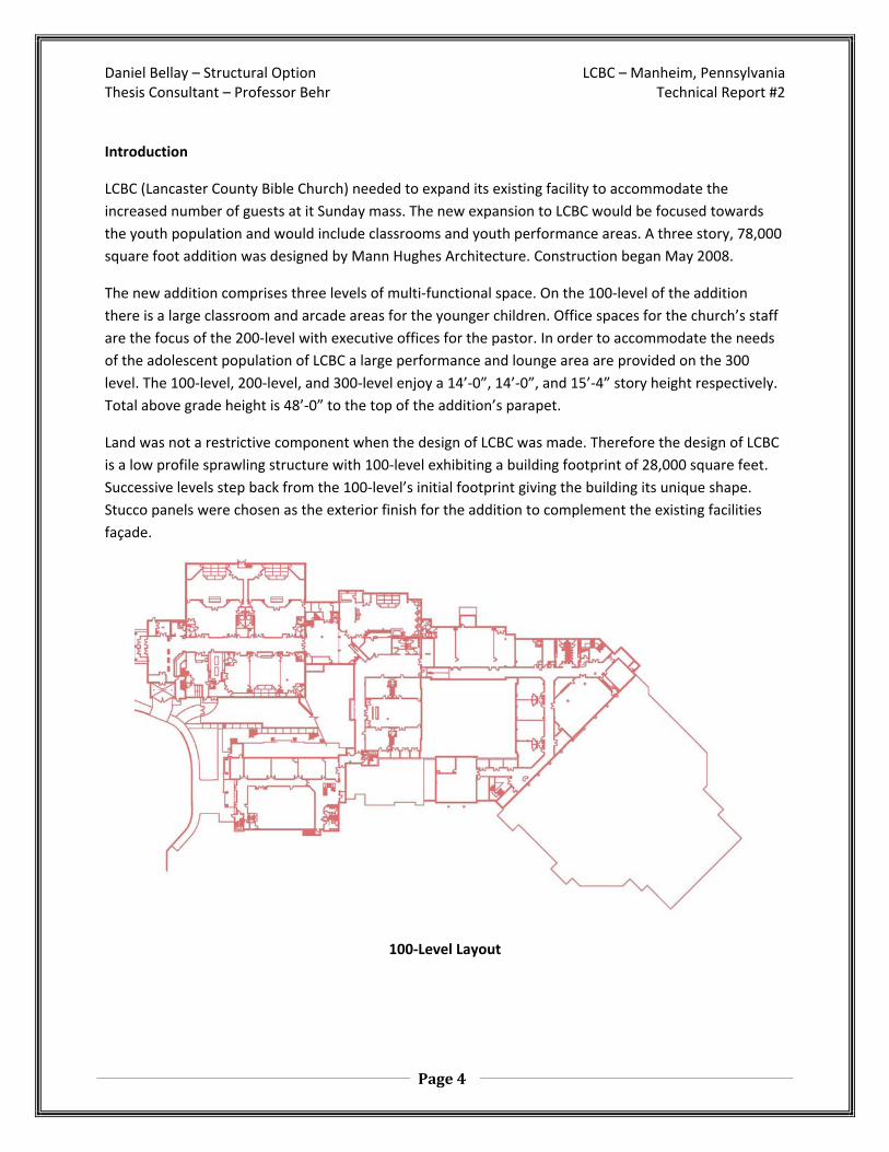
Introduction
LCBC (Lancaster County Bible Church) needed to expand its existing facility to accommodate the
increased number of guests at it Sunday mass. The new expansion to LCBC would be focused towards
the youth population and would include classrooms and youth performance areas. A three story, 78,000
square foot addition was designed by Mann Hughes Architecture. Construction began May 2008.
The new addition comprises three levels of multi‐functional space. On the 100‐level of the addition
there is a large classroom and arcade areas for the younger children. Office spaces for the church’s staff
are the focus of the 200‐level with executive offices for the pastor. In order to accommodate the needs
of the adolescent population of LCBC a large performance and lounge area are provided on the 300
level. The 100‐level, 200‐level, and 300‐level enjoy a 14’‐0”, 14’‐0”, and 15’‐4” story height respectively.
Total above grade height is 48’‐0” to the top of the addition’s parapet.
Land was not a restrictive component when the design of LCBC was made. Therefore the design of LCBC
is a low profile sprawling structure with 100‐level exhibiting a building footprint of 28,000 square feet.
Successive levels step back from the 100‐level’s initial footprint giving the building its unique shape.
Stucco panels were chosen as the exterior finish for the addition to complement the existing facilities
façade.
100‐Level Layout

Daniel Bellay – Structural Option LCBC – Manheim, Pennsylvania Thesis Consultant – Professor Behr Technical Report #2
Page 5
Foundations
Various sized spread footings were designed to support column loads at LCBC. An F20, 2’x2’x12”, is the
smallest spread footing found at LCBC. Reinforcing for an F20 footing is provided by (3) #4 bars in each
direction. Interior columns require the largest spread footing and exhibit F110’s, 11’x11’x2’. Reinforcing
for F110 is provided by (18) #7 bars in each direction. Typically spread footings are square however
there are two rectangular footings, F 70x90 and F50x60. Load bearing masonry walls are supported by
continuous spread footings that measure 24”x12”. Horizontal reinforcing for the continuous footings is
provided by (3) #4 bars. Vertical reinforcing is provided by #6 dowels with 4” hooks @ 8” O.C.
Typical Foundation Detail

Daniel Bellay – Structural Option LCBC – Manheim, Pennsylvania Thesis Consultant – Professor Behr Technical Report #2
Page 6
Flooring System
Reinforced concrete on metal decking was selected as the primary flooring system for LCBC. A 4”
concrete slab is reinforced with 6x6 10/10 welded wire mesh. 1 ½”, 26 gauge metal deck provides
additional strength for the concrete deck. This one‐way floor system transfers gravity loads to
supporting girders and columns. Concrete used be 3,000 psi strength.
The typical bay size at LCBC is 38’‐4” x 25’‐0”, however bay sizes vary to reflect the multi‐functional
nature of the building. On the 200‐level floor framing the smallest bay size is 10’‐9” x 16’‐10” while the
largest bay is 65’‐0” x 38’‐8”. The 300‐hundred level roof framing is dominated by a massive 67’‐0”x 63’‐
4” frame which provides a large open space required for the performance area below.
Framing for the flooring is provided by various open web steel joists. Longer spans at LCBC, typically 38’‐
4”, demand 26K9 or 26K10 open web steel joists. Shorter spans, typically 18’‐25’, are typically supported
by 18K4 open web steel joists. The lightest open web steel joist is an 8K1. In contrast the long spans
located in the roof framing implement a 36LH12.
The 100‐level flooring system is a slab on grade system. A 4” thick concrete slab is poured over a 6mm
polyurethane vapor barrier. Underneath the vapor barrier on 4” of crushed stone on compacted earth.

Daniel Bellay – Structural Option LCBC – Manheim, Pennsylvania Thesis Consultant – Professor Behr Technical Report #2
Page 7
Gravity System
Gravity loads at LCBC are resisted by a simple steel framing system. The majority of the columns are W‐
shaped with the exception of a few HSS 4x4x3/8 columns. Typically columns will start 7” below grade
and continue to the roof level. There are a few columns that start on the 200‐level but they are the
minority. Column sizes vary depending on how many floors the column supports and if they are interior
or perimeter columns. A W10x60 is the heaviest column at LCBC and a W8x31 is the lightest. Beams and
girders are W‐shaped and range from a W12x16 to a W30x99.
Daniel Bellay – Structural Option LCBC – Manheim, Pennsylvania Thesis Consultant – Professor Behr Technical Report #2
Page 8
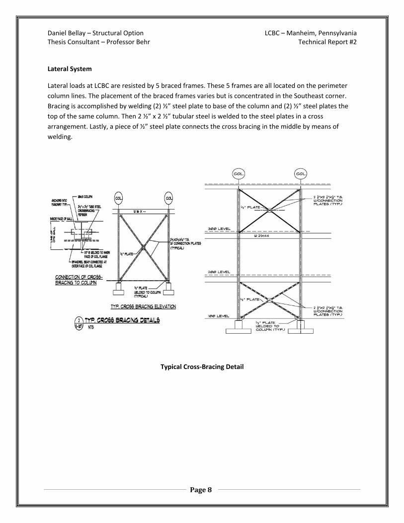
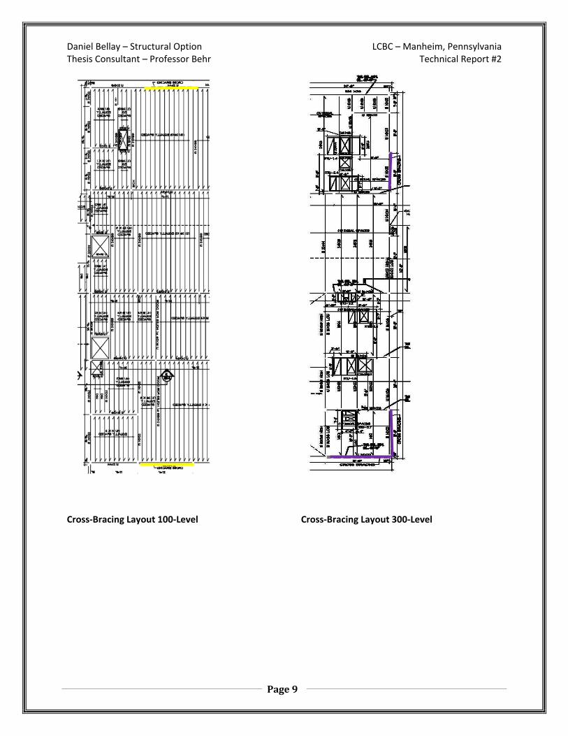
Lateral System
Lateral loads at LCBC are resisted by 5 braced frames. These 5 frames are all located on the perimeter
column lines. The placement of the braced frames varies but is concentrated in the Southeast corner.
Bracing is accomplished by welding (2) ½” steel plate to base of the column and (2) ½” steel plates the
top of the same column. Then 2 ½” x 2 ½” tubular steel is welded to the steel plates in a cross
arrangement. Lastly, a piece of ½” steel plate connects the cross bracing in the middle by means of
welding.
Typical Cross‐Bracing Detail
Daniel Bellay – Structural Option LCBC – Manheim, Pennsylvania Thesis Consultant – Professor Behr Technical Report #2
Page 9
Cross‐Bracing Layout 100‐Level Cross‐Bracing Layout 300‐Level

Daniel Bellay – Structural Option LCBC – Manheim, Pennsylvania Thesis Consultant – Professor Behr Technical Report #2
Page 10
Roofing
Two different flat roofing systems are implemented at Lancaster County Bible Church. The first flat roof
system uses three‐inch rigid insulation supported by 1 ½” metal decking. A single ply roofing membrane
provides moisture protection. Tectum “E” structural roofing panels are used above the youth
performance area. The panels are 6‐inces thick and are constructed of: OSB sheathing, EPS insulation,
and substrate.
Typical Roof Construction Detail
Building Envelope
The predominate façade of Lancaster County Bible Church is stucco. A ¾”prefabricated stucco panel
called EIFS is installed on top of 5/8” dense glass. A vapor barrier provides moisture protection. 6” metal
studs placed 16” on center provide support for the building’s façade. R‐19 batt insulation provides
thermal resistance for the wall construction. Gypsum board is used for the interior finish.
Typical Wall Section

Daniel Bellay – Structural Option LCBC – Manheim, Pennsylvania Thesis Consultant – Professor Behr Technical Report #2
Page 11
Codes:
Building Code IBC 2003 Structural Steel AISC Specification for Structural Steel Buildings AISC Manual of Steel Construction – Allowable Stress Design, 9th Addition Vulcraft Steel Joist and Steel Girders 2003 Concrete ACI Details and Detailing of Concrete Reinforcement, ACI 315 ACI Manual of Engineering and Placing Drawings for Reinforced Concrete Structures, ACI 315R Design Loads International Building Code 2000 American Society of Civil Engineers (ASCE), ASC‐ 7
Gravity Loads (Dead & Live Loads):
Live Loads
Area Design Load (psf)
Corridor 100
Office 100
Stairs 60
Storage Rooms 80
Roof 30
Dead Loads
Description Design Load (psf)
Floor Dead Load 50
Partitions 20
Framing 8
Ceilings 3
Mechanical Ductwork 3
Daniel Bellay – Structural Option LCBC – Manheim, Pennsylvania Thesis Consultant – Professor Behr Technical Report #2
Page 12
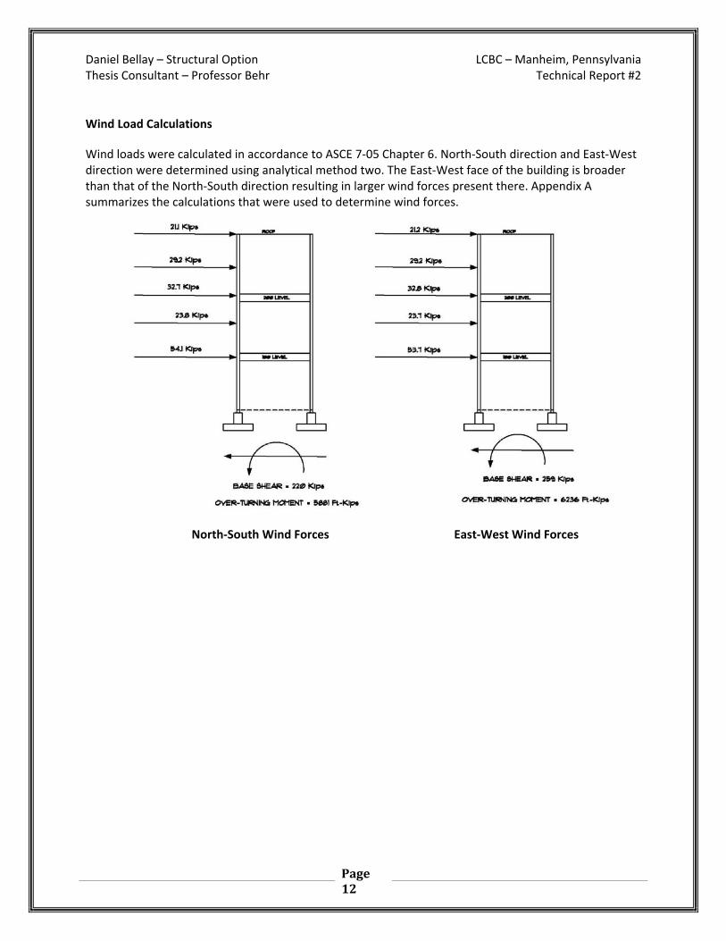
Wind Load Calculations
Wind loads were calculated in accordance to ASCE 7‐05 Chapter 6. North‐South direction and East‐West direction were determined using analytical method two. The East‐West face of the building is broader than that of the North‐South direction resulting in larger wind forces present there. Appendix A summarizes the calculations that were used to determine wind forces.
North‐South Wind Forces East‐West Wind Forces

Daniel Bellay – Structural Option LCBC – Manheim, Pennsylvania Thesis Consultant – Professor Behr Technical Report #2
Page 13
Seismic Calculations
Seismic loads on Lancaster County Bible Church are calculated according to IBC Chapter 6. The seismic
flowcharts located in this portion of the code detail the calculations used to determine lateral forces
that are produce during a seismic event. Lancaster County Bible Church is a steel framed structure thusly
it is light, 333.3 Kips, compared to a similar sized concrete building. In addition, Manheim Pennsylvania
is not a seismic area further reducing seismic forces. Appendix B summarizes calculations used to
perform the seismic analysis.
Seismic Forces

Daniel Bellay – Structural Option LCBC – Manheim, Pennsylvania Thesis Consultant – Professor Behr Technical Report #2
Page 14
To better understand the lateral system present at Lancaster County Bible Church two methods of
calculations were employed. The first method of analysis is a hand calculation for the two different
braced frames. Hand calculations were compared to a Staad generated computer model. Results from
the two different methods are then compared for differences.
METHOD 1: Hand calculations
A Staad computer model was generated for the each braced frame. Each braced frame was loaded using
a 1000 pound force. Deflections of the frame were then calculated by the computer. Using the inverse
of the frame deflection produces a frames relative stiffness. Assuming the center of mass to be at the
geometric center of the structure the center of rigidity is calculated using a frame’s relative stiffness.
Using the following equations Table (FILL IN THE BLANK) was compiled.
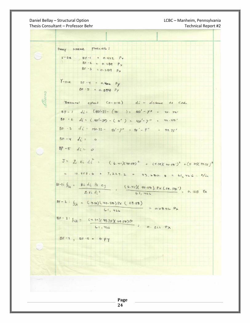
• Direct Shear Force Equation: Fix direct =( kix * P ) / ( ΣKix ) and Fiy direct = ( kiy * P ) / ( ΣKiy )
• Torsion Forces: Fi torsion =( ki*di*Px*ey ) / (Σkidi2) • Total Forces: Fi = Fidirect ± Fitorsion

Daniel Bellay – Structural Option LCBC – Manheim, Pennsylvania Thesis Consultant – Professor Behr Technical Report #2
Page 15
Calculation Summary Approximate Frame Stiffness
Story Load Direction
Frame Load (Kips)
Displacement (Inches)
Stiffness Stiffness Factor
Xi (Inches)
KiyXi (kips)
Center of Rigidity
X
BF‐1 1 0.156 6.41 0.422 0 0
1 BF‐2 1 0.228 4.39 0.289 0 0
BF‐3 1 0.228 4.39 0.289 1684 7392.8 486.7”
Sum = 15.19 7392.8
Y BF‐4 1 0.228 4.39 0.406 1504 6602.6
1 BF‐5 1 0.156 6.41 0.594 1504 9640.6 1504”
Sum = 10.80 16,243.2
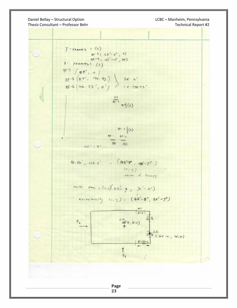
Center of Mass (X,Y): (62’‐8”, 70’‐2)
Center of Rigidity (X,Y): (40’‐7”, 125’‐4”)
Eccentricity (X,Y): (22’‐1”, 55’‐2”)
Simplified Braced‐Frame Layout
BF‐1 (84.0’,0.0’) BF‐2 (106.3’,0.0’)
BF‐3 (125.33’,0.0’)
BF‐4 (125.33’,120.0’)
BF‐5 (84.0’,140.33’)
Daniel Bellay – Structural Option LCBC – Manheim, Pennsylvania Thesis Consultant – Professor Behr Technical Report #2
Page 16
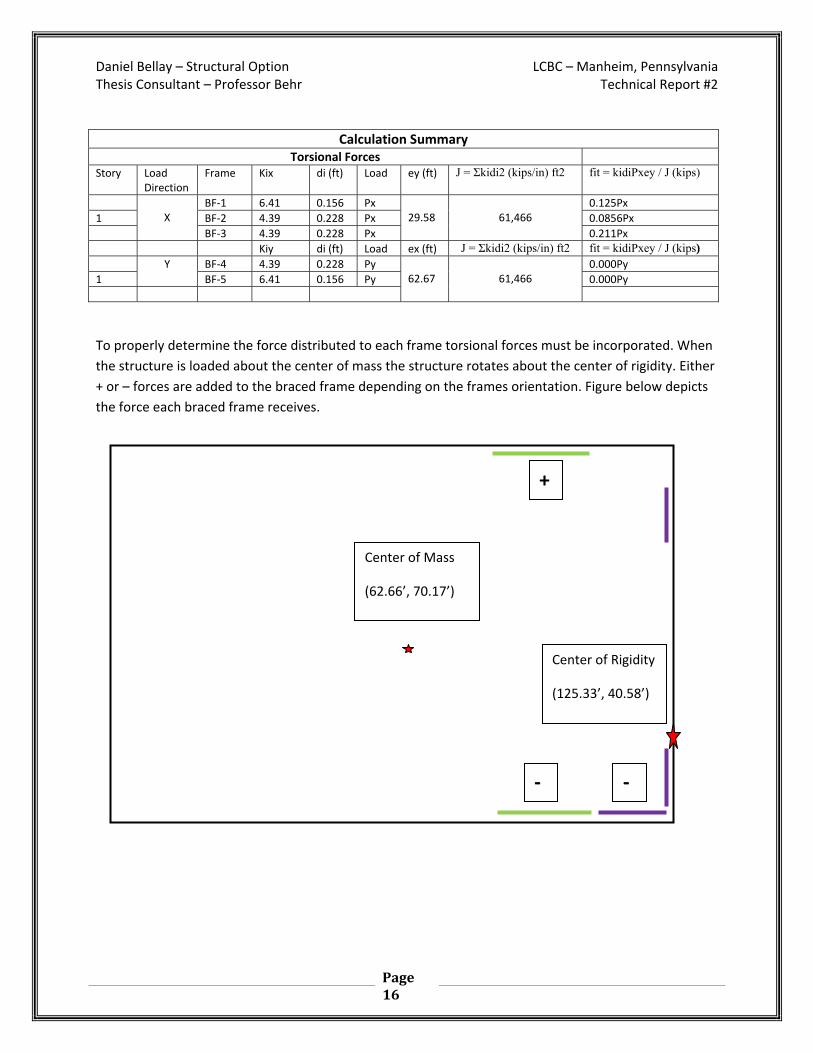
Calculation Summary Torsional Forces
Story Load Direction
Frame Kix di (ft) Load ey (ft) J = Σkidi2 (kips/in) ft2 fit = kidiPxey / J (kips)
X
BF‐1 6.41 0.156 Px 29.58
61,466
0.125Px
1 BF‐2 4.39 0.228 Px 0.0856Px
BF‐3 4.39 0.228 Px 0.211Px
Kiy di (ft) Load ex (ft) J = Σkidi2 (kips/in) ft2 fit = kidiPxey / J (kips) Y BF‐4 4.39 0.228 Py
62.67
61,466 0.000Py
1 BF‐5 6.41 0.156 Py 0.000Py
To properly determine the force distributed to each frame torsional forces must be incorporated. When
the structure is loaded about the center of mass the structure rotates about the center of rigidity. Either
+ or – forces are added to the braced frame depending on the frames orientation. Figure below depicts
the force each braced frame receives.
Center of Mass
(62.66’, 70.17’)
Center of Rigidity
(125.33’, 40.58’)
+
‐ ‐

Daniel Bellay – Structural Option LCBC – Manheim, Pennsylvania Thesis Consultant – Professor Behr Technical Report #2
Page 17
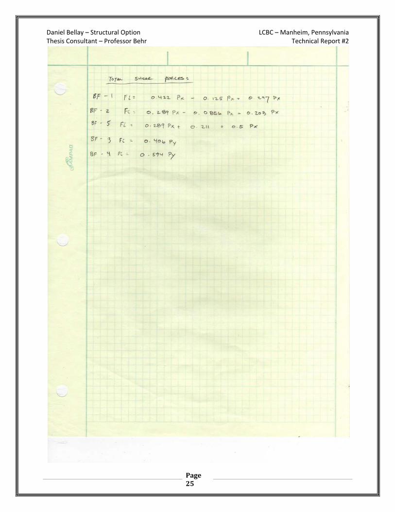
The resulting forces from hand calculation method are summarized in the table below
Hand Calculations – Total force Calculations Direction Frame Direct Force Torsional Force Total Force
BF‐1 0.422 Px ‐ 0.125 = 0.297 Px
X BF‐2 0.289 Px ‐ 0.0856Px = 0.203 Px
BF‐5 0.289 Px + 0.211Px = 0.500 Px
Y BF‐3 0.406 Py 0 0 = 0.406 Py
BF‐4 0.594 Py 0 0 = 0.594 Py
Method Two: Staad Analysis
The second method used to analyze the lateral system at Lancaster County Bible Church was a computer
analysis of the building. The first step in the computer analysis was the modeling of the entire building in
Staad.Pro_2007. Following the modeling of the structure wind loads, seismic loads, and lateral forces
were applied to determine forces present in the braced frames.
Once modeling of Lancaster County Bible Church was completed the center of mass for the structure
needed to be determined. Self weight of the members was applied and the resulting in the following
forces:
Mx = 21,312,871 ft x lbs
My = 0 ft x lbs
Daniel Bellay – Structural Option LCBC – Manheim, Pennsylvania Thesis Consultant – Professor Behr Technical Report #2
Page 18
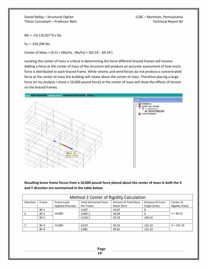
Mz = ‐23,110,927 ft x lbs
Fy = ‐333,296 lbs
Center of Mass = (X,Y) = (Mx/Fy , Mz/Fy) = (63.33’ , 69.34’)
Locating the center of mass is critical in determining the force different braced frames will receive.
Adding a force at the center of mass of the structure will produce an accurate assessment of how much
force is distributed to each braced frame. While seismic and wind forces do not produce a concentrated
force at the center of mass the building will rotate about the center of mass. Therefore placing a large
force (in my analysis I chose a 10,000 pound force) at the center of mass will show the effects of torsion
on the braced frames.
Resulting brace frame forces from a 10,000 pound force placed about the center of mass in both the X
and Y direction are summarized in the table below.
Method 2 Center of Rigidity Calculation Direction Frame Frame Load
Applied (Pounds) Total Horizontal Force Per Frame
Percent of Total Story Shear (%) K
Distance Di From Origin (Feet)
Center of Rigidity (Feet)
BF‐1 10,000
3,467 34.67 0 Y = 49.52 X BF‐2 3,005.1 30.04 0
BF‐5 3,529.1 35.29 140.33
Y BF‐3 10,000 5,019 50.19 125.33 X = 125.33
BF‐4 4,981 49.81 125.33

Daniel Bellay – Structural Option LCBC – Manheim, Pennsylvania Thesis Consultant – Professor Behr Technical Report #2
Page 19
Wind Drift From E‐W Wind Force Story Story Height iches Story Drift
(inches) Allowable Story Drift Δwind = H / 400 (in.)
Total Drift (inches)
Allowable Total Drift
Δwind = H/400
Serviceability Check Actual < Allowable
Roof 522 0.288 0.435 0.616 1.305 Okay
3 348 0.328 0.435 0.408 0.870 Okay
2 174 0.080 0.435 0.080 0.435 Okay
Wind Drift From N‐S Wind Force Story Story Height iches Story Drift
(inches) Allowable Story Drift Δwind = H / 400 (in.)
Total Drift (inches)
Allowable Total Drift
Δwind = H/400
Serviceability Check Actual < Allowable
Roof 522 0.172 0.435 0.280 1.305 Okay
3 348 0.108 0.435 0.154 0.870 Okay
2 174 0.046 0.435 0.046 0.435 Okay
Hand Verification of Output (Portal Method)
An estimate of braced frame deflection caused by wind loads was performed using the Portal Method.
Wind loads were used from the computer analysis. Computer generated wind loads were what was used
to determine the drift in the story drift. Therefore using the same wind loads will produce a result that is
closer to the computer analysis. East‐West direction wind loading was chosen for the hand calculations.
The resulting deflection of the building was 0.230” at the roof level. This deflection is less than the
1.305” allowed by code. Appendix D summarizes the calculations employed for the hand verification.
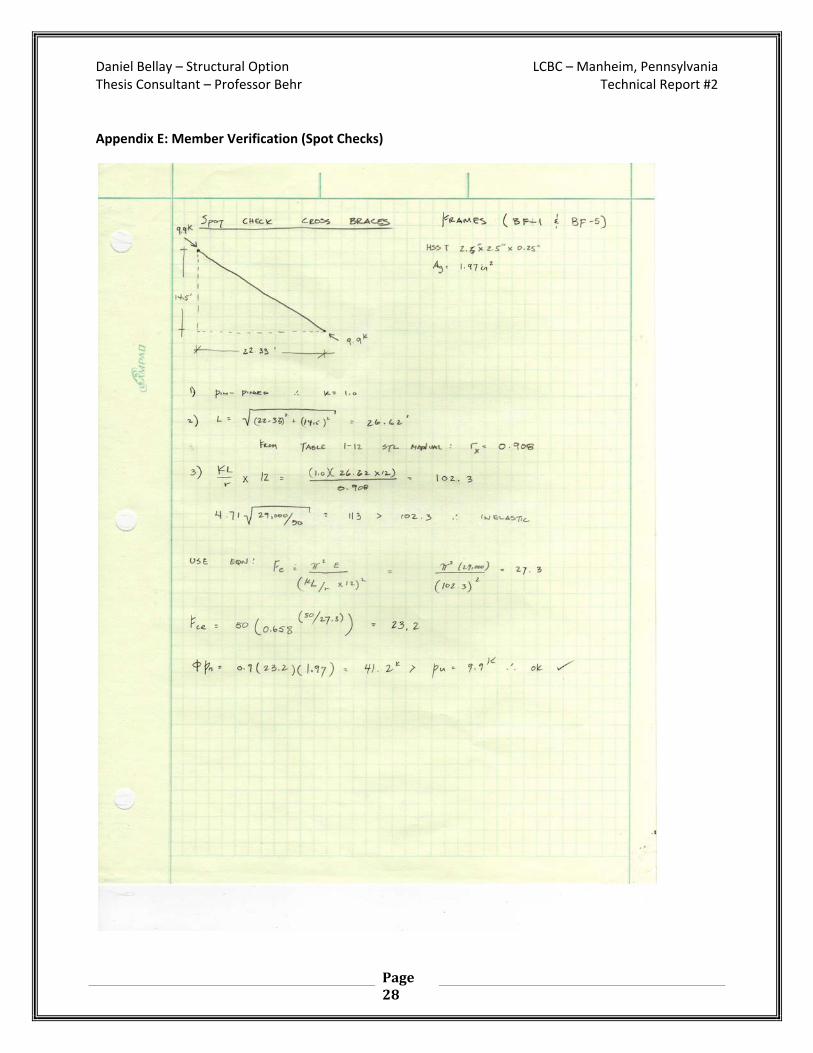
Spot Checks
Member verifications were performed on critical braced frames. Two bracing typical bracing elements
were analyzed for their strength. It was assumed the non‐critical bracing elements would be able to
resist lateral loading once the critical bracing elements were found to be sufficient. Calculations for
these spot checks can be found in Appendix E.
Conclusions
In the third technical report of the Lancaster County Bible Church, an analysis of the lateral system was performed to verify that the lateral system meat all code requirements. Confirmation of the design was done using a 3‐D model of the existing lateral system was created using Staad.Pro_2007. Two preliminary methods of analysis were employed to confirm the computer generated results. My results found that the lateral system at Lancaster County Bible Church is sufficient to resist lateral loads and deflection. Therefore my calculations agreed with the structural engineers calculations.
Daniel Bellay – Structural Option LCBC – Manheim, Pennsylvania Thesis Consultant – Professor Behr Technical Report #2
Page 20
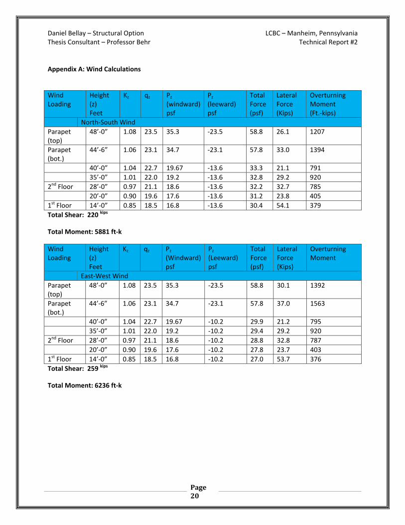
Appendix A: Wind Calculations
Wind Loading
Height (z) Feet
Kz qz Pz (windward)psf
Pz (leeward) psf
Total Force (psf)
Lateral Force (Kips)
Overturning Moment (Ft.‐kips)
North‐South Wind
Parapet (top)
48’‐0” 1.08 23.5 35.3 ‐23.5 58.8 26.1 1207
Parapet (bot.)
44’‐6” 1.06 23.1 34.7 ‐23.1 57.8 33.0 1394
40’‐0” 1.04 22.7 19.67 ‐13.6 33.3 21.1 791
35’‐0” 1.01 22.0 19.2 ‐13.6 32.8 29.2 920
2nd Floor 28’‐0” 0.97 21.1 18.6 ‐13.6 32.2 32.7 785
20’‐0” 0.90 19.6 17.6 ‐13.6 31.2 23.8 405
1st Floor 14’‐0” 0.85 18.5 16.8 ‐13.6 30.4 54.1 379
Total Shear: 220 kips
Total Moment: 5881 ft‐k
Wind Loading
Height (z) Feet
Kz qz Pz (Windward)psf
Pz (Leeward) psf
Total Force (psf)
Lateral Force (Kips)
Overturning Moment
East‐West Wind
Parapet (top)
48’‐0” 1.08 23.5 35.3 ‐23.5 58.8 30.1 1392
Parapet (bot.)
44’‐6” 1.06 23.1 34.7 ‐23.1 57.8 37.0 1563
40’‐0” 1.04 22.7 19.67 ‐10.2 29.9 21.2 795
35’‐0” 1.01 22.0 19.2 ‐10.2 29.4 29.2 920
2nd Floor 28’‐0” 0.97 21.1 18.6 ‐10.2 28.8 32.8 787
20’‐0” 0.90 19.6 17.6 ‐10.2 27.8 23.7 403
1st Floor 14’‐0” 0.85 18.5 16.8 ‐10.2 27.0 53.7 376
Total Shear: 259 kips
Total Moment: 6236 ft‐k

Daniel Bellay – Structural Option LCBC – Manheim, Pennsylvania Thesis Consultant – Professor Behr Technical Report #2
Page 21
Appendix B: Seismic Calculations
Seismic Loading Properties Value Source
Occupancy Category I Drawings
Seismic Importance Factor (I) 1.0 Drawings
Mapped Spectral Response Accelerations
Short Period (SS) 0.343 USGS Website
1‐Second Period (Ss) 0.086 USGS Website
Site Class
Spectral Response Coefficients
Short Period (SDS) 0.229 USGS Website
1‐Second Period (SD1) 0.057 USGS Website
Seismic Design Category (SDC) C Drawings
Response Modification Factor (R) 5 ASCE 7‐05 Table12.2‐1
Approx. Period of the Structure (Ta)
hn (ft.) 43’‐4” Drawings
Ct 0.020 ASCE 7‐05 Table 12.8‐2
X 0.75 ASCE 7‐05 Table 12.8‐2
Ta 0.346 ASCE 7‐05 Eqn. 12.8‐7
Long‐Period Transition Period (TL) 6 ASCE 7‐05 Fig. 22‐15
Seismic Response Coefficient (Cs) 0.033 ASCE 7‐05 Eqn. 12.8‐2
Exponent Related to the Structure(k) 0.923 ASCE 7‐05 12.8.3
Floor Area Height Range (Feet)
Slab (psf) Kips
Partitions (psf) Kips
Roof Dead (psf) Kips
Floor Weight (Kips)
3 19,270 28’‐0” 43’‐4” 50 964 20 385 15 289 1638
2 25,303 14’‐0” 28’‐0” 50 1265 20 506 0 0 1771
1 27,869 0’‐0” 14’‐0” 0 0 20 557 0 0 557.4
Total 72,442 5180

Daniel Bellay – Structural Option LCBC – Manheim, Pennsylvania Thesis Consultant – Professor Behr Technical Report #2
Page 22
Appendix C: Center of Rigidity Calculations
Daniel Bellay – Structural Option LCBC – Manheim, Pennsylvania Thesis Consultant – Professor Behr Technical Report #2
Page 23
Daniel Bellay – Structural Option LCBC – Manheim, Pennsylvania Thesis Consultant – Professor Behr Technical Report #2
Page 24
Daniel Bellay – Structural Option LCBC – Manheim, Pennsylvania Thesis Consultant – Professor Behr Technical Report #2
Page 25

Daniel Bellay – Structural Option LCBC – Manheim, Pennsylvania Thesis Consultant – Professor Behr Technical Report #2
Page 26
Appendix D: Portal Method

Daniel Bellay – Structural Option LCBC – Manheim, Pennsylvania Thesis Consultant – Professor Behr Technical Report #2
Page 27
Daniel Bellay – Structural Option LCBC – Manheim, Pennsylvania Thesis Consultant – Professor Behr Technical Report #2
Page 28
Appendix E: Member Verification (Spot Checks)

Daniel Bellay – Structural Option LCBC – Manheim, Pennsylvania Thesis Consultant – Professor Behr Technical Report #2
Page 29