LAN INTERFACE \
23
US005625675A Umted States Patent [19] [11] Patent Number: 5,625,675 Katsumaru et al. [45] Date of Patent: A r. 29 1997 9 [54] VOICE MAIL CONHVIUNICATION SYSTEM 5,351,276 9/1994 Doll, Jr. et a1. ........................ .. 379/67 5,375,068 12/1994 Palmer et a1. ....... .. . 364/514 [75] Inventors: lkuko Katsumaru, Machida; Junji 5,334,829 1/1995 Heileman, Jr- et al- 379/67 Fukuzawa‘ Sagamihara; Masato 5,406,557 4/1995 Baudoin .................. .. 379/89 amih . 5,414,762 5/1995 Flisik et al 379/94 grad?‘ asrzg an 02?; 22am“ Takada‘ 5,440,624 8/1995 Scho?, 11 ........ .. 379/201 galmh ’ P 5,450,488 9/1995 Pugalzewski et a1. 379/67 _ _ . , 5,487,103 l/l996 Richardson, Jr. et a1. 379/88 [73] Asslgnee' Hltachl, Ltd” Tokyo- Japan 5,497,373 3/1996 Hulen et a1. ............................ .. 379/79 [21] Appl. No.: 500,690 OTHER PUBLICATIONS [22] Filed: Jul. 11, 1995 Fujitsu Journal. vol. 19, No. 2. 1993. pp. 67 and 68. [30] Foreign Applica?on Priority Data Primary Examiner-Krista M. Zele Jul. 14,1994 [JP] Japan .................................. .. 6-161811 Assistant Examiner-Daniel S. Hunter 6 - Attorney, Agent, or Firm—Fay. Sharpe. Beall, Fagan. Min [51] Int. Cl. .................................................... .. H04M 1/64 nigh & McKee [52] US. Cl. ................. .. 379/67; 379/89; 379/84 [58] Field of Search ................................ .. 379/67. 88. 89. [571 ABSTRACT 379/84‘ 207* 94; 370/61 The voice mail system includes a voice mail exchanger and 56 R f Ct d a mail server. A voice mail communication between a [ 1 e erences l e telephone and a terminal device. such as a client computer, Us, PATENT DOCUMENTS is registered in a LAN based multi-media mail box. A PBX 4 853 952 8/1989 J hm [a1 379,89 based voice mail apparatus and a LAN based multi-media , , ac an e . ...................... .. - - - - - 4,935,954 6/1990 Thompson et a1. . 379/96 320E121; arssggz?tfguzggh that “me mfonmnon can 5,029,200 7/1991 Haas et a1. .... .. . 379/207 y ' 5,274,696 12/1993 Perelman ..... .. 379/89 5,333,266 7/1994 Boaz et a1. ............................ .. 395/200 11 Claims, 14 Drawing Sheets 5 s r" voICE MAIL 155E STEP APPARATUS 0,3,4 10 11 We TELEPHONE LINE 1 5 / DIRECTORY PBX “4 INFORMATION ) ( MAIL BOX) I I N 2A I N 25 mm MAIL DIRECTORY EXCHANGEH N3 1 SERVER v23 I MAIL sERvER Irv?“ DIRECTORY MAIL sTEP1,s I INTERFACE V26 I INTERFACE V27 LAN v2 LAN V235 INTERFACE I INTERFACE Z 92 Vi _ V\ _ N 9s 92 9s STEM 94 1b 28 /~1a CoMPuTERA STEP 7 ( COMPUTER B LAN INTERFACE \ REAL TIME 1: voIcE E5 MAIL : , CA-MQ'AJJNI‘ $521123; ivlbp'léRFACE 'NTEHFACE m‘ INTERFACE f‘ 1273- 5 125a 126a 27a gg : _ 5i MAIL APPLl 27b TELEPHONE APPLICATION MODULE i_§ $13355 i \ 20a \ 21a l c o ’ VOICE l/O N \égi/Igel/ N ‘23 DEVICE ‘2b
Transcript of LAN INTERFACE \

US005625675A
Umted States Patent [19] [11] Patent Number: 5,625,675 Katsumaru et al. [45] Date of Patent: A r. 29 1997 9
[54] VOICE MAIL CONHVIUNICATION SYSTEM 5,351,276 9/1994 Doll, Jr. et a1. ........................ .. 379/67 5,375,068 12/1994 Palmer et a1. ....... .. . 364/514
[75] Inventors: lkuko Katsumaru, Machida; Junji 5,334,829 1/1995 Heileman, Jr- et al- 379/67 Fukuzawa‘ Sagamihara; Masato 5,406,557 4/1995 Baudoin .................. .. 379/89
amih . 5,414,762 5/1995 Flisik et al 379/94 grad?‘ asrzg an 02?; 22am“ Takada‘ 5,440,624 8/1995 Scho?, 11 ........ .. 379/201
galmh ’ P 5,450,488 9/1995 Pugalzewski et a1. 379/67 _ _ . , 5,487,103 l/l996 Richardson, Jr. et a1. 379/88
[73] Asslgnee' Hltachl, Ltd” Tokyo- Japan 5,497,373 3/1996 Hulen et a1. ............................ .. 379/79
[21] Appl. No.: 500,690 OTHER PUBLICATIONS
[22] Filed: Jul. 11, 1995 Fujitsu Journal. vol. 19, No. 2. 1993. pp. 67 and 68.
[30] Foreign Applica?on Priority Data Primary Examiner-Krista M. Zele Jul. 14,1994 [JP] Japan .................................. .. 6-161811 Assistant Examiner-Daniel S. Hunter
6 - Attorney, Agent, or Firm—Fay. Sharpe. Beall, Fagan. Min [51] Int. Cl. .................................................... .. H04M 1/64 nigh & McKee
[52] US. Cl. ................. .. 379/67; 379/89; 379/84 [58] Field of Search ................................ .. 379/67. 88. 89. [571 ABSTRACT
379/84‘ 207* 94; 370/61 The voice mail system includes a voice mail exchanger and 56 R f Ct d a mail server. A voice mail communication between a
[ 1 e erences l e telephone and a terminal device. such as a client computer, Us, PATENT DOCUMENTS is registered in a LAN based multi-media mail box. A PBX
4 853 952 8/1989 J hm [a1 379,89 based voice mail apparatus and a LAN based multi-media , , ac an e . ...................... .. - - - - -
4,935,954 6/1990 Thompson et a1. . 379/96 320E121; arssggz?tfguzggh that “me mfonmnon can 5,029,200 7/1991 Haas et a1. .... .. . 379/207 y '
5,274,696 12/1993 Perelman ..... .. 379/89
5,333,266 7/1994 Boaz et a1. ............................ .. 395/200 11 Claims, 14 Drawing Sheets
5 s r"
voICE MAIL
155E STEP APPARATUS 0,3,4
10 11
We TELEPHONE LINE 1 5 / DIRECTORY
PBX “4 INFORMATION ) ( MAIL BOX) I I N 2A I N 25
mm MAIL DIRECTORY EXCHANGEH N3 1 SERVER v23 I MAIL sERvER Irv?“
DIRECTORY MAIL sTEP1,s I INTERFACE V26 I INTERFACE V27
LAN v2 LAN V235 INTERFACE I INTERFACE Z 92
Vi _ V\ _ N 9s 92 9s STEM 94 1b
28 /~1a CoMPuTERA STEP 7 ( COMPUTER B
LAN INTERFACE \ REAL TIME 1: voIcE E5 MAIL :
, CA-MQ'AJJNI‘ $521123; ivlbp'léRFACE 'NTEHFACE m‘ INTERFACE f‘ 1273- 5 125a 126a 27a gg : _ 5i MAIL APPLl
27b TELEPHONE APPLICATION MODULE i_§ $13355 i
\ 20a \ 21a l
c o ’ VOICE l/O N \égi/Igel/ N ‘23 DEVICE ‘2b

US. Patent Apr. 29, 1997 Sheet 1 of 14 5,625,675
5 a f/
/ TELE vOICE MAHg. PHONE sTEP APPARATU
0,3,4 10 11
a TELEPHONE LINE
DlRECTORY PBX “4 INFORMATION MA'L BOX
V I /\/ 2A N28
vOICE MAIL DIRECTORY / 23 , 24 EXCHANGER (\13 SERVER \/ MAIL sERvER \/
DIRECTORY , 26 MAIL , 27 ‘ STEP1,5 INTERFACE V INTERFACE V
LAN LAN V288 INTERFACE INTERFACE
7 9-2
K n A) I ,r’ V\s-s 9-2 U\9-s - N
28 sTEP2 1b / /~Ia COMPuTERA STEP7 ( COMPLITERB
/_/
LAN INTERFACE
CSféET-IME MA"? REAL 5 DIRECTORY MAIL =3 2 5 82%???" INTERFACE INTERFACE 5; 'NTERFACE g Il'ggE m.“ E INTERFACE 127a. 5 INT. '
i \asa 1‘26a \27a §§ § 8 g 5 ‘% ?e?” i 2% 21b 5 TELEPHONE APPLICATION MODULE a? MODULE g L ..................................... -_\ _________ "I L .... __‘\ ...... ".1
\zoa Km vOICE I/O vOICE l/O DEVICE A’ ‘23 DEVICE N121)

U.S. Patent Apr. 29, 1997 Sheet 2 0f 14 5,625,675
FIG. 2
/J VOICE MAIL EXCHANGER
LINE INTERFACE VOICE PACKET/ vCICE FILE
CONNECTION VO'OE CONVERTER
li’é‘éim/ CONTROLLER 891; y A voICE 3° TION \33 PACKET \F/IEfé-ETIME RECEPTOR CONVERT: COMMUNL DIRECTORY MAIL EH CAT|ON INTERFACE INTERFACE
INTERFACE
LAN INTERFACE
\ 281
FIG. 3
KIND OF ATTRIBUTE ATI'FIIBUTE VALUE
USER IDENTIFIER
MAIL ACCESS CONTROL INFORMATION
TELEPHONE NUMBER
TELEPHONE ADDRESS

US. Patent
(A)
(B)
(C)
Apr. 29, 1997 Sheet 3 0f 14 5,625,675
F1 F2 F13 F4 F5 H H H H H
COM SADR DADR STE LNO DTELNO N 41-1
F1 F2 H H
COM STAT N 41-2
F1 /_/
COM N 41-3
F1 F2 F13 F4 F5 H H H H H
COM SMID DMlD TITLE MSG

U.S. Patent Apr. 29, 1997 Sheet 4 0f 14 5,625,675
FIG. 6
VOICE MAIL DIRECTORY MAIL TELEPHONE PBX COMPUTER B EXCHANGER SERVER SERVER
\7\/ 6 Vv 4 V-v 3 1b Vv 2A V-\/ 28 CONNECTION
REQUEST CONNECTION TEP 0'1 REQUEST
STEP 0'2 ADDRESS RETRIEVAL STEP 1 k
RESPONSE l (ADDRESS INFORMATION)
CONNECTION
STEP 2 REQUEST RESPONSE
RESPONSE (NO)
RESPONSE : (YES) SWITCHING TO VOICE ) (YES) (MAIL REGISTRATION
(VOICE GUIDANCE ) < COMMUNICATION STEPS > NOTIFICATION
DISCONNECTION (VO‘CE F'LE ) REQUEST T DISCONNEOTION GENERATION '
STEP 4'1 REQUEST
STEP 4-2 MAIL ACCESS CONTROL STEP 5 INFORMATION RETRIEVAL ;
4 RESPONSE I
STEP 6 MAIL REGISTRATION _ k
RESPONSE l A

U.S. Patent Apr. 29, 1997 ‘Sheet 5 of 14 5,625,675
5 a [J
,_/ voICE MAIL TELE
PHONE APFARATus
11
a
DIRECTDRY PBX m 4 INFORMATION MA'L BOX
I N 2A N 25
voICE MAIL DIRECTORY 23 24 ./~\/ I
DIRECTORY [V26 MAIL ,V27 INTERFACE INTERFACE
LAN , 28A LAN , 28B INTERFACE ‘’ INTERFACE ‘’
7 STEP 1,3 I A L STEP 4/ l T 9'2
“95/ N[\9-2 “X93 9-4 N" \ 1a 1b
( CoMFuTERA ,28 STEPS ( CoMFuTERB // /"
LAN INTERFACE ; I STEP2
r ------- "? ------------- "I ---------------- ,- ------------- m1
= II M I : DIRECTORY MAIL 55 ; REAL E 82%?" INTERFACE INTERFACE 55 'NTERFACE 5 TIME MAIL E INTERFACE 55 127 . 5 :QCE ‘NT' : \ X \ l I a i ' 5 25a 26a 27a 55 g g g 5 ;: MAIL APPLI- I I :3 CATIoN 5 25b 27b % TELEPHONE APPLICATION MODULE 5% MODULE 2 L ..................................... .-\ ......... .-:-. ____ -.\ ...... ..;
\ 20a K 21a
voICE I/C N12 voICE I/o N DEVICE a DEVICE 12b

US. Patent
(
COMPUTER A
V\IEI - 1b
STEP 1
STEP 2
SWITCHING TO VOICE MAIL REGISTRATION
STEP 3
GENERATION
STEP 4
(VOICE FILE )
Apr. 29, 1997
FIG. 8
COMPUTER B
Sheet 6 0f 14
DIRECTORY SERVER
ADDRESS RETRIEVAL
VMA
RESPONSE I (ADDRESS INFORMATION)
CONNECTION REQUEST
V
RESPONSE
; (N0)
MAIL ACCESS CONTROL INFORMATION RETRIEVAL
I RESPONSE (MAIL ACCESS
#CONTROL INFORMATION) ‘ |
MAIL REGISTRATION
5,625,675
MAIL SERVER
A RESPONSE I
A

US. Patent Apr. 29, 1997 Sheet 7 0f 14 5,625,675
FIG. 9 - 0-2 40-3 I/_/ 40 1 1/ 4 l/_/
[MAIL SENDEFI] {RECEPTION DATE] [ATTACHED INFORMATION]
1. Terada Mon Oct. 25 10:17’ Hitachi
2. Tele. Serv Mon Oct. 25 20:50 Voice Mail from Outline
3. Katsuma Tue Nov. 30 09:59 Translation
4. TeIe. Serv Tue Nov. 30 15: 32 Voice Mail from 3425
5. Tele. Serve Tue Nov. 30 18: 11 Voice Mail from Outline
L 40
FIG. 10
DIRECTORY MAIL coMPuTERA COMPUTER B SERVER sERvER
v\1a \Ib 2A ‘R28 MAIL INQUIRY ‘
RESPONSE I ‘(RECEIVED MAIL INFORMATION)
MAIL DESIGNATION ‘
‘RESPONSE (VOICE MAIL)
A A I A

US. Patent Apr. 29, 1997 Sheet 8 0f 14 5,625,675
11 FIG.
11 1O
VOICE MAIL APPARATUS
/_/
TELE~ PHONE
DIRECTORY
N28
B m
T b
U W.
s w
m W. a 9.. O N
v V 9 c
v b
, f f If 1( n_T b
R Tl WW Sm m
E E E .l
V C C E
R A A mum E F F L E IV S R R [A EC. b OE
RE E mMmTg? VD
l AT WT H?VW
m Mm m 4
9
3 8 A 2 2 8
2
A v V V I .......................... , z m m E - u. m a
T u C a . n m
Y Y E E a w a m a w N E M K
H R 9 u H A L. 0 CC C M " umE \\ H._IOIW\“\ T? TM an. L w " MN mmo N
EV mun“ mm a m 1 CM m
m % m T W T A} 1 ( Hunununuuununnu
DS DW W 1 m “
Q2 m m. n m M w %
M1 / w m m n w m 2 ..
/A " mm 0 \K N
A F " MN M u
3 m/" 1.. u
u N .
T _ _
m N / YE a m m
l u Mm M n m
5 n H II
KH 9 W “ mum \ m u E m m \ m m m W w mu m
. _ DII . |
A u A . O
E _
_ ‘ D
mm m E w u v
.E _ 0
Va 4 1:! AM M m w m u 2. 7. "T UNFZ P m
P (A El "L%W©%\\ E n m K mmmorm E m
S mRVCmI T n
F I I I I I I I I l
o l I
l
I I I l I l l I I I l I I
l I L

US. Patent Apr. 29, 1997 Sheet 9 of 14 5,625,675
FIG. 12
KIND OF ATTRIBUTE ATTRIBUTE VALUE
USER IDENTIFIER
MAIL ACCESS CONTROL INFORMATION
TELEPHONE NUMBER
KIND OF TELEPHONE
TELEPHONE ADDRESS

US. Patent Apr. 29, 1997 Sheet 10 0f 14 5,625,675
VOICE MAIL VOICE MAIL DIRECTORY P 00 P T APPARATUS TELE HONEB PBX EXCHANGER M U ERA SERVER
v v v v v v ADDRESS
STEP1 RETRIEVAL ‘
CONNECTION 4 RESPONSE
CONNECTION <REQUEST STEP2
CONNECTION <HEQUEST STEP 2-1 : REQUEST STEP 22
RESPONSE
(NO) _
VOICE MAIL VOICE MAIL CONNECTION SWITCHING
‘REQUEST IS SET ‘ | STEP3
RESPONSE (YES) RESPONSE
(YES) .7 RESPONSE
(YES)
/ COMMUNICATION , . 4 \\I > STEP
DISCONNECTION REQUEST
DISCONNECTION 4 REQUEST
DISCONNECTION T
REQUEST
A A A A A A

US. Patent Apr. 29, 1997 Sheet 11 of 14 5,625,675
FIG. 14
5 s f‘/
,_/ vOICE MAIL TELE
PHONE APPARATUS
II STEP 0,3,6]
——II I—— DIRECTORY
MAIL BOX PBX m4 'NFOHMAT'ON - V I F’ 25
vOICE MAIL DIRECTORY EXCHANGEH m3 SERVER MAIL sERvER
I: A ~_‘-_ A I, v ~.__v v
.5 STEP5 T ;' COMPuTERA COMPuTERB
I: I \ 1a "L \ 1b I: N128 "V \ ~
N ~
LINE INTERFACE VOICE MAIL vOICE PACKET/ OPERATION vOICE FILE
CONNECT‘ON RECEPTOR CONvERTER
‘"3165 CONTROLLER sTREAM/ \ \31 \33
_ 30 vOICE PACKET sgfé-ETIME REAL TIME CONVERT- COMMUNL DIRECTORY vOICE MAIL EH CAT‘ON INTERFACE COMMUNICATION INTERFACE
INTERFACE INTERFACE _
\32 \25I-1 \zei \zsi-z 2B. \ 27i STEP 2,3,7 / '
LAN INTERFACE

US. Patent Apr. 29, 1997 Sheet 12 of 14 5,625,675
FIG. 15
VOICE MAIL vOICE MAIL DIRECTORY MAIL TELEPHONE PBX OPERATION EXCHANGER RECEPTOR SERVER SERVER
V V V CONNECTION I
REQUEST E CONNECTION
STEP 0-1 REQUEST ‘
STEP 0.2 ADDRESS RETRIEVAL STEPI _
RESPONSE | (ADDRESS INFORMATION)
CONNECTION
STEP 2 REQUEST
RESPONSE RESPONSE ‘ (NO)
RESPONSE 4 (YES)
(YES) ‘
[VOICE SUIOANCE\ COMMUNICATION STEP 3 SERWCE
<L J>QDENTIFICATION ) MAIL ACCESS CONTROL INFORMATION RETRIEVAL
RESPONSE (MAIL CONTROL
lINFORMATION) ‘(USER CONFIRMATION)
STEP 5 MAIL READ I ‘
‘RESPONSE (VOICE MAIL) ‘(FILE CONVERSION)
< COMMUNICATION STEP 6 > OISCONNEOTION REQUEST L DISCONNECTION
STEP 7 REQUEST : OISCONNECTION REQUEST
A A A. A A

US. Patent Apr. 29, 1997 Sheet 13 of 14 5,625,675
FIG. 16 4
H 11
PBX
MAIL BOX
STEP 02V f__/ 3 10 H 28 Y
VOICE MAIL EXCHANGER MAIL SERVER
STEP 3 '
X l STEP 4 i STEP 5 m I rx H7
K V T V T\ ' STEP 1
COMPUTER A m/ 13 CQMPUTER B m, 1b
I I VOICE I/O VOICE l/O
TELEPHONE A DEVICE TELEPHONE B DEVICE
\ 63 112a 1 6b 11%
FIG. 17
LINE INTERFACE ,/ 29
CONNECTION CONTROLLER _/ 3°
VOICE STREAM/ vOICE PACKET VOICE MAIL CONVERTER OPERATION MAIL DIRECTORY
RECEPTOR INTERFACE INTERFACE
\34 \31 \27i \26 LAN INTERFACE

US. Patent Apr. 29, 1997 Sheet 14 of 14 5,625,675
FIG. 18
r] 10
ATTRIBUTE VALUE _ KIND OF ATI'RIBUTE
TELEPHONE NUMBER
MAIL ACCESS CONTROL INFORMATION
vOICE MAIL MAIL TELEPHONEA PBX T EP 0 EB EL H N EXCHANGER SERVER
Vv?a VV4 VVBD W3 W28 CONNECTION
STEPO REQUEST L CONNESTION STEP 0-1 HEQUE T
VOICE MAIL R9128? SE SWITCHING =
IS SET vOICE MAIL CONNECTION
STEP 02 REQUEST I _
RESPONSE ‘ RESPONSE (YES)
_ (YES) ‘
‘ vOICE GUIDANCE
6 STEP‘ > NOTIFICATION [VOICE FILE
DISCONNECTION \GENERATION STEPZ REQUEST _
DISCONNECTION REQUEST
[ OBTAINING OF MAIL STEPs ACCESS CONTROL
\INFORMATION MAIL REGISTRATION _
STEP 4
‘ RESPONSE
A A A A A

5,625,675 1
VOICE MAIL COMIVIUNICATION SYSTEM
BACKGROUND OF THE INVENTION
1. Field of the Invention The present invention relates to a voice mail system and
a voice mail exchanger and more particularly to an inte grated mail system and a voice mail exchanger which can exchange voice messages between a user of a computer applied device (terminal device). having a voice communi cation function. and a user of a general telephone connected to a switch.
2. Description of the Prior Art As a conventional mail system which can handle voice
information, a voice mail apparatus attached to a PBX for taking in telephones and a mail server for text or multimedia including an image using a calculator applied device repre sented by a personal computer or a workstation as a terminal are known.
Avoice mail apparatus is a mail system attached to a PBX and a user of each telephone taken in the PBX transmits or receives a voice message via the voice mail apparatus. For example. when a communication partner is absent. a user of a telephone makes a telephone call to the mail box of the communication partner and registers a voice message in the voice mail apparatus. Auser who is a destination of the voice mail accesses the voice mail apparatus using an interface which is intrinsic to the telephone such as operating a push button so as to fetch the message from the mail box and can hear it via the telephone. On the other hand. a mail server is a system used to
transmit or receive messages between users of personal computers or workstations connected to a LAN and as multimedia personal computers and multi-media worksta tions have appeared. a multi-media mail system which can transmit and receive voice and image messages in addition to text messages has been developed. An example of an o?ice system integrating a telephone
based voice communication system and a LAN based data communication system is described in Fujitsu Journal. Vol. 19, No. 2. 1993. pp. 67 and 68. .
In the system described in the aforementioned literature, each user uses a telephone and a personal computer together, performs voice communication using the telephone, and registers a voice message in a voice mail apparatus. The user transmits or receives multimedia mails using the personal computer.
In this system, a list of the voice mails received by the voice mail apparatus can be displayed on the screen of a personal computer. When a user designates a voice mail to be received on the screen of the personal computer. the system rings a bell of the nearest telephone and outputs the message to this telephone. Reception of multi-media mails is indicated by a reception lamp attached to the telephone and the voice mail can be heard from the voice output device of the personal computer.
Although the aforementioned general voice mail appara tus is an effective means in smooth proceeding of transfer of a voice message, operations such as mail registration. reception. and cancel are performed by an interface which is based on an intrinsic button operation of the telephone, so that there is a problem imposed in the operability and the apparatus is not fully utilized actually. On the other hand. a multi-media mail system is com
paratively inexpensive and excellent in operability because a mail operation can be performed by using a GUI (graphical
10
15
25
30
35
45
50
55
65
2 user interface) of a personal computer. Since voice infor mation and image information can be managed in a ?le format. they can be shared and reused easily between application programs at each terminal device.
However. in the aforementioned conventional integrated o?ice system. although integration of telephone based voice communication service and LAN based data communication service is realized. the voice mail apparatus for handling voice mails and the multi-media mail system for handling multi-media mail are independently mounted and it is nec essary for a user to select properly one of these two mail systems.
Since the voice information is distributed to and managed by the voice mail apparatus and the multi-media mail system. a problem arises in that all of the voice information cannot be shared or reused between the application pro grams.
SUMIVIARY OF THE INVENTION
An object of the present invention is to provide a voice mail system which can be accessed from both a general telephone and a telephone terminal device connected to a LAN.
Another object of the present invention is to provide an integrated mail system in which a PBX based voice mail apparatus and a LAN based multi-media mail system are integrated.
Still another object of the present invention is to provide a voice mail exchanger which can to share and reuse a PBX based voice mail and a LAN based voice mail. To accomplish the above objects, the voice mail commu
nication system of the present invention comprises a signal transmission line. a plurality of terminal devices having a voice mail communication function which are connected to the signal transmission line. a mail server which is con nected to the transmission line and stores a plurality of voice mails and manages the addresses of the voice mails. a switch for exchanging voice signals of at least a plurality of telephones, and a voice mail exchanger which is connected to the switch and the transmission line and converts a connection protocol of at least one of the telephones to a voice mail connection protocol and communicates the con verted voice mail at least with the mail server and at least one of the terminal devices. The voice mail exchanger of the present invention is a
voice mail exchanger which has an interface connected to a switch for taking in a plurality of telephones and an interface having a voice I/O function connected to a LAN including a plurality of terminal devices and enables communication between the telephones on the switch side and the terminal devices on the LAN side. wherein the voice mail exchanger includes a converting means for converting a connection protocol ?'om a telephone on the switch side to a connection protocol between the terminal devices on the LAN side, a switching means for switching the connection protocol from the aforementioned telephone on the switch side to voice mail protocol processing. a converting means for converting a telephone number to mail control information, and a sending means for sending the voice information from the aforementioned telephone to the mail server connected to the LAN as a voice mail by the mail control information. More concretely. in the voice mail system of the present
invention. a plurality of computers (terminal devices) having a voice I/O function and the mail server are connected to each other with the LAN. and each terminal device stores a voice mail for an answering machine and another text or

5 ,625,675 3
multi-media mail in the same mail box via the mail server. and a mail of an optional medium can be fetched from each terminal device.
In the voice mail system of the present invention, the PBX is connected to the LAN via the voice mail exchanger, and the signal form or protocol of voice and mail transmitted and received between the telephones on the PBX side and the terminal devices on the LAN side is converted by the voice mail exchanger. and voice mails for an answering machine from the telephones on the PBX side can be stored in the mail box of the mail server connected to the LAN. The voice mail exchanger of the present invention
includes. for example. a voice communication means on the LAN for performing voice communication between the exchanger and a computer (terminal device) connected to the LAN . a connection control means for converting a connection signal for controlling the PBX to the voice communication procedure on the LAN. an address convert ing means for converting a telephone number to a computer address on the LAN. and a voice format converting means during communication for converting between the voice information format on the telephone line and the voice information format on the LAN and sets a call between a general telephone. the voice mail apparatus. and an appli cation program on the computer.
In another embodiment of the voice mail exchanger of the present invention. the exchanger has an automatic voice mail operation switching means for deciding absence of a user or a communication disabled state and setting a call by automatically switching the communication processing to the voice mail processing and the linked processing from communication to voice mail operation can be performed in the user absence state or communication disabled state.
In still another embodiment of the voice mail exchanger of the present invention. the exchanger has a voice format converting means during storing for converting between the voice information format on the LAN and the voice infor mation format which can use an application program. a request interpretation means for interpreting user input information, a mail address converting means for converting a telephone number to a mail address. and a mail operating means to an existing mail system and a voice mail operation can be performed from a general telephone. The present invention having the aforementioned consti
tution has the following operation and function. According to the present invention. voice mails for an
answering machine and other mails handled by a LAN terminal are stored in the same mail box. Therefore. these mails can be handled in a uni?ed manner from each terminal device and voice mails can be fetched easily.
In the voice mail exchanger of the present invention. when a connection request to a computer on the LAN is received from a general telephone. the communication pro cedure can be converted by the connection control means and the call setting processing with a LAN terminal (computer) can be performed by the address converting means and the voice communication means on the LAN. When the LAN terminal to be received cannot reply, the processing can be transferred to the voice mail registration into the main box by the automatic voice mail operation switching means and the voice information from a general telephone registered in the mail box can be fetched at any time from the terminal device on the LAN side.
Furthermore. when the voice mail exchanger receives a connection request to the voice mail apparatus from the terminal on the LAN side. by converting the communication
10
15
25
35
40
50
55
65
4 procedure by the connection control means. performing the call setting processing with the PBX, and converting the voice format. a voice mail can be registered in the voice mail appratus of the telephone on the PBX side from the appa ratus on the LAN side.
The foregoing and other objects. advantages. manner of operation and novel features of the present invention will be understood from the following detailed description when read in connection with the accompanying drawings.
BRIEF DESCRIPTION OF THE DRAWINGS
FIG. 1 is a system block diagram showing a ?rst embodi ment of the voice/data integrated communication system of the present invention.
FIG. 2 is a drawing showing the constitution of the voice mail exchanger 3 shown in FIG. 1.
FIG. 3 is a drawing showing an example of information stored in the directory 10 shown in FIG. 1.
FIG. 4 is a drawing showing the constitution of a con nection request packet, a connection response packet. and a disconnection request packet used in the aforementioned communication system.
FIG. 5 is a drawing showing the constitution of a mail registration request packet. which is a sequence diagram indicating the registration procedure for a voice mail for an answering machine from a LAN telephone shown in the ?rst embodiment.
FIG. 6 is a sequence diagram showing the procedure for registering a voice mail for an answering machine from an external telephone in the ?rst embodiment.
FIG. 7 is a system block diagram for explaining an operation for registering a voice mail for an answering machine from a telephone connected to the LAN in the ?rst embodiment.
FIG. 8 is a sequence diagram showing the procedure for registering a voice mail for an answering machine from a telephone connected to the LAN in the ?rst embodiment.
FIG. 9 is a drawing showing an example of an output screen displaying a list of received mails.
FIG. 10 is a sequence diagram showing the procedure for fetching a voice mail from the mail box 11.
FIG. 11 is a system block diagram showing a second embodiment of the voice/data integrated communication system of the present invention.
FIG. 12 is a drawing showing the constitution of the directory in the second embodiment.
FIG. 13 is a sequence diagram showing the procedure for registering a voice mail for an answering machine from a telephone connected to the LAN in the second embodiment.
FIG. 14 is a system block diagram showing a third embodiment of the voice/data integrated communication system of the present invention.
FIG. 15 is a sequence diagram showing the procedure for registering a voice mail for an answering machine from an external telephone in the third embodiment.
FIG. 16 is a system block diagram showing a fourth embodiment of the voice/data integrated communication system of the present invention.
FIG. 17 is a drawing showing the constitution of the voice mail exchanger 3 shown in FIG. 16.
FIG. 18 is a drawing showing the constitution of the directory in the fourth embodiment.
FIG. 19 is a sequence diagram showing the procedure for registering a voice mail for an answering machine from a telephone in the fourth embodiment.
5 DETAILED DESCRIPTION OF THE PREFERRED EMBODIMENTS
The embodiments of the present invention will be explained hereunder with reference to the accompanying drawings.
Embodiment 1
A system for performing both telephone type real time voice communication and store type voice communication on the LAN using a computer (LAN based telephone system) including a voice 110 device will be explained. In this system. a mail server connected to the LAN as a mail system for recording an answering machine is used and a mail for an answering machine sent to a user of this system from a user of a general telephone is registered in the mail server on the LAN. ‘
FIG. 1 shows the constitution of the voice/data integrated office communication system A numeral 1 (1a, 1b, - - - ) indicates client computers
which can perform voice communication and 12 (12a, 12b) indicates voice I/O devices installed in the client computers 1 and each client computer 1 inputs and outputs voice via each of the voice I/O devices 12. A numeral 2A indicates a directory server computer for
managing telephone numbers assigned to each of the client computers 1 and ID information of the mail box used by a user. 2B a mail server computer for managing a text mail and a voice mail of a user. 3 a voice mail exchanger for enabling registration of a voice mail into a mail server 2B from a telephone 6v and registration of a mail into a voice mail apparatus 5 from the client computers 1. 4 a PBX. and 5 a voice mail apparatus attached to the PBX.
Each of the client computers 1 and each of the server computers 2 are connected to each other by a LAN 7. The voice mail exchanger 3 has an interface connected to the LAN 7 and an interface connected to a telephone line 8 so as connect the client computers 1. the server computers 2. and the PBX 4. Each of the client computers 1 (1a, 1b) has telephone
application modules 20 (20a, 20b) for real time voice communication and mail application modules 21 (21a, 21b) for mail transmission and reception. Each of the telephone application modules 20 includes a
real time voice communication interface module 25. a directory interface module 26. and a mail interface module 27. The real time voice communication interface module 25
is a module for performing voice communication between the client computers via a LAN interface module 28 and has functions for connecting or disconnecting a call between the client computers. packeting inputted voice information, reproducing a voice packet. and transmitting or receiving a voice packet. The directory interface module 26 is a module for com
municating with a directory server 23 installed in the com puter 2A via the LAN interface module 28 and has functions for retrieving a telephone number from a user identi?er and retrieving mail control information from a telephone num ber. The mail interface module 27 is a module for communi
cating with a mail server 24 installed in the computer 2B via the LAN interface module 28 and has functions for gener ating a voice ?le. performing mail registration processing. and registering a voice mail for an answering machine. Each of the mail application modules 21 is an application
module for transmitting and receiving a normal text mail and
5,625,675
20
25
35
45
50
55
65
6 voice mail and includes a mail interface module 27 and communicates with the mail server 24 via the LAN interface module 28. The directory server 23. as shown in FIG. 3 for example.
manages user discrimination information (user name. etc.). mail control information (mail ID. password. etc.). tele phone numbers. and telephone addresses by the directory 10. The voice mail exchanger 3 comprises a voice commu
nication support block and a voice mail support block between the computers 1 and the telephone 6. The voice communication support block. as shown in
FIG. 2. comprises a line interface module 29. a connection controller module 30. a voice stream/voice packet converter module 32. a real time voice communication interface module 251', a directory interface module 261', and a LAN interface module 281'. The connection controller module 30 is used to convert
mutually the PBX connection procedure and the real time voice communication procedure and receives a connection signal from the PBX via the line interface module 29. transfers it to the real time voice communication interface module 25i, and communicates with the client computers 1 via the LAN interface module 281'. Inversely. the connection controller module 30 receives a connection request from the client computers 1 via the real time voice communication interface module 25i and transfers it to the PBX 4 via the line interface module 29. The voice stream/voice packet converter module 32 con
verts mutually between the voice stream which is a voice format on the telephone line and the voice packet which is a voice format on the LAN. The voice mail support block comprises a voice mail
operation receptor module 31. a voice packet/voice ?le converter module 33. and a mail interface module 271'. The voice mail operation receptor module 31 has a
request interpretation function (voice recognition. DTMF (dual tone multi-frequency) detection. etc.) for obtaining information necessary for voice mail registration and read ing from a communication partner and operates mails via the mail interface module 271'. I
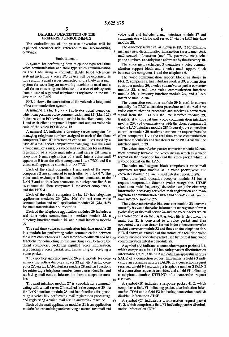
The voice packet/voice ?le converter module 33 converts mutually between the voice information management format (voice ?le) of the mail server 24 and the voice packet which is a voice format on the LAN. A voice ?le fetched from the main box 11 is converted to a voice packet and then converted to a voice stream format in the voice stream/voice packet converter module 32 and ?ows on the telephone line. FIG. 4 shows an example of the format of a real time voice communication procedure packet used by the real time voice communication interface module 25. A symbol (A) indicates a connection request packet 41-1.
which comprises a ?eld F1 indicating packet discrimination information COM. a ?eld F2 indicating an apparatus address SADR of a connection request transmitter. a ?eld F3 indi cating an apparatus address DADR of a connection request receiver. a ?eld F4 indicating a telephone number STELNO of a connection request transmitter. and a ?eld F5 indicating a telephone number DTELNO of a connection request receiver. A symbol (B) indicates a response packet 41-2. which
comprises a ?eld F1 indicating packet discrimination infor mation COM and a ?eld F2 indicating connection enabled! disabled information STAT. A symbol (C) indicates a disconnection request packet
41-3. which comprises a ?eld F1 indicating packet discrimi nation information COM.

5,625,675 7
FIG. 5 shows the format of a mail registration request packet 41-4 used by the mail interface module 27. The mail registration request packet 41-4 comprises a
?eld F1 indicating packet discrimination information COM, a ?eld F2 indicating discrimination information (mail ID. etc.) SMID of a mail transmitter, a ?eld F3 indicating discrimination information DMID of a mail receiver. a ?eld F4 indicating title information TITLE expressing the content of a message which is freely set by a mail transmitter, and a ?eld F5 indicating a mail text MSG.
Operation Example 1: Registration of a Voice Mail for an Answering Machine from a General Telephone The transmission procedure for a voice mail for an
answering machine to a user of the computer B from a user of the telephone 6 will be explained with reference to FIGS. 1 and 6.
A user of the computer B (1b) registers his telephone number in the PBX 4 beforehand so as to connect the line to the voice mail exchanger 3 when a connection request is issued externally to him. When the user of the telephone 6 makes a telephone call
to the user of the computer B according to the normal telephoning procedure, a connection request is issued to the PBX 4 from the telephone 6 (Step 0-1) and the PBX 4 transfers the connection request to the voice mail exchanger 3 (Step 0-2). The voice mail exchanger 3 transfers the aforementioned
connection request to the connection controller module 30 via the line interface module 29. The connection controller module 30 converts the connection request from the tele phone 6 to a real time voice communication procedure between the computers which will be described below and connects a call to the user of the computer B.
Firstly, the connection controller module 30 issues an address retrieval request to the directory server 1b (23) (Step 1) on the basis of the telephone number (destination tele phone number) of the user of the computer B and obtains the information of the telephone address from the response of the directory server. Next. the connection controller module 30 sends a call connection request to the real time voice communication interface module 2512 of the computer B (Step 2) via the real time voice communication interface module 25i. When a connection negative response (NO) is outputted from the real time voice communication interface module 25b of the computer B or the real time voice communication interface module 251' itself judges that the computer B is in the inoperable state. the connection con troller module 30 automatically switches the mode to the voice mail registration mode.
In the voice mail registration mode, the connection con troller module 30 establishes a call between the PBX and the telephone 6 which is a calling source by returning a positive response to the PBX so as to set a communication state (Step 3) and then starts the voice mail operation receptor module 31 and the voice mail operation receptor module 31 informs the telephone 6 of the voice guidance for requesting regis tration of a voice mail for an answering machine. When voice information (a voice stream) is inputted from the telephone 6, the connection controller module 30 starts the voice stream/voice packet converter module 32 and converts the input voice stream to a voice packet. The voice packet is transferred to the voice packet/voice ?le converter module 33 via the voice mail operation receptor module 31 and edited in a voice ?le. The editing of the voice ?le is continued until the connection controller module 30 is informed of a disconnection request from the telephone 6.
20
25
35
40
45
55
65
8 When the telephone 6 issues the disconnection request
and the connection controller module 30 is informed of it (Step 4). the voice mail operation receptor module 31 requests retrieval of mail access control information to the directory server 23 on the basis of the telephone number of the user of the computer B (Step 5) and obtains the control information by the response from the directory server 23. When the mail control information is obtained already at Step 1. Step 5 can be omitted.
Next. the voice ?le is registered in the mail box 11 of the mail server computer 2B (mail server 24) (Step 6). In this case, information such a display element indicating that the corresponding mail is a voice mail for an answering machine and the telephone number of the calling source for discrimi nating the mail calling source is added to the mail body in the format of the mail registration request packet 414. For example. a mail ID for telephone services is set in the SMID ?eld (F2) and the telephone number of a telephone calling source is set in the TITLE ?eld (F4). For a telephone line other than ISDN, the telephone number of a calling source is generally unknown, so that information indicating that it is a communication request from the telephone line is set in place of the telephone number.
Operation Example 2: Registration of a Voice Mail for an Answering Machine from a Client Computer The transmission procedure for a voice mail for an
answering machine to a user of the computer B from a user of the computer A will be explained with reference to FIGS. 7 and 8.
The user of the computer A starts the telephone applica tion module 20a and makes a telephone call to the user of the computer B. Ifthe user of the computerAdesignates the user of the computer B by a user identi?er such as name. when the telephone application module 20a issues an address retrieval request to the directory server 23 (Step 1) and obtains information such as the telephone number of the user of the computer B and the telephone address by a response from the directory server 23. the telephone application module 20a sends a call connection request to the'real time voice communication interface module 25b of the computer B via the real time voice communication interface module 25a (Step 2). When a connection negative response is outputted from
the real time voice communication interface module 25b or the real time voice communication interface module 25a itself discriminates that the computer B is in the inoperable state. the telephone application module 20a automatically switches the mode to the voice mail registration mode.
In the voice mail registration mode. the telephone appli cation module 20a issues a mail control information retrieval request to the directory server 23 on the basis of the telephone number of the user of the computer B and obtains the mail control information (Step 3). When the mail control information is obtained already at Step 1, this step can be omitted.
Next. to process a voice mail for an answering machine from the user of the computer A, the mail interface module 27a is started. The mail interface module 27a edits voice information inputted from the voice I/O device 12a in a voice ?le. When the end of voice input is detected, the voice ?le is registered in the mail box 11 via the mail server 24 (Step 4). In this case, to discriminate the mail calling source, the mail ID for telephone services is set in the SMID ?eld (F2) of the mail registration request packet 41-4 and the telephone number of the telephone calling source is set in the TITLE ?eld (F4).

5 ,625,675
Operation Example 3: Reception of a Voice Mail for an Answering Machine The processing procedure when a user of the client
computer B receives a voice mail for an answering machine addressed to him which is registered in the main box 11 will be explained with reference to FIGS. 9 and 10. The user of the computer B starts the mail application
module 21b (not written) and performs the mail reception processing (Step 7 shown in FIG. 1. Step 5 shown in FIG. 7). When the mail server 213 is inquired about a received mail. received mail information is replied from the mail server 2B and the mail application module 21b outputs received mail information 40 on the display screen. for example. in the format shown in FIG. 9. In this example, the received mail information comprises a mail sender display 40-1. a reception date display 40-2. and an attached infor mation 403. In the mail sender display 40-1. a voice mail for an answering machine is distinguished from other mails by a mail ID (SMLD of the mail registration request packet) for telephone services. In the attached information display 403. discrimination information (‘TITLE of the mail registration request packet. telephone number information. or informa tion indicating reception from the telephone line) of a mail sender (telephone calling source). When the user of the computer B designates the desired
mail on the display screen. he can read the voice mail for an answering machine from the mail box by the same operation as that for other normal mails (text) and delete useless mails from the mail box.
Embodiment 2
In this embodiment, the operation when the client com puter A (la) communicates with the general telephone 6 and the voice mail apparatus 5 will be explained with reference to FIGS. 11. 12. and 13. In this embodiment, as shown in FIG. 12, information (kind of telephone) for discriminating the kind of telephone used by a user is registered in the directory 10.
Operation Example 1: Mail Registration in the Voice Mail Apparatus by a Client Computer Assuming that if the partner user is absent when the user
of the computer A makes a telephone call to the user of the telephone 6, the telephone 6 is automatically switched to the voice mail apparatus 5 by the function of the PBX 4. the transmitting procedure for a voice mail for an answering machine will be explained hereunder with reference to FIGS. 11 and 13. The user of the computer A starts the telephone applica
tion module 20a and makes a telephone call to the user of the telephone 6. When the user of the computer A who is a calling source designates the name of the user of the telephone 6 which is a partner by the user identi?er. the telephone application module 20a inquires the computer 2A of the directory server 23 about address information on the basis of the user identi?er and obtains information such as the telephone number. telephone address. and kind of tele- 1 phone relating to the user of the telephone 6 (Step 1). When the kind of the telephone of the partner is “general telephone”. the telephone application module 20a sends a call connection request to the real time voice communication interface module 25i of the voice mail exchanger 3 via the real time voice communication interface module 25a (Step' 2). The real time voice communication interface module 25i
sends the connection request to the connection controller module 30 and the connection controller module 30 converts
15
25
30
35
40
45
50
55
65
10 the connection request to a control signal of the PBX 4 and sends it to the PBX 4 via the line interface module 29 (Step 2-2). When the partner user is absent (NO is replied). the
connection request is automatically switched to the voice mail apparatus 5 by the function of the PBX 4 (Step 3). When the connection controller module 30 is informed of a connection response signal from the voice mail apparatus 5 via the PBX 4. the real time voice communication interface module 25i establishes a call between the voice mail appa ratus 5 and the real time voice communication interface module 25a of the computer A (Step 4). When the voice mail apparatus 5 and the real time voice
communication interface module 250 of the computer A enter the communication state, the user of the computer A generates a voice mail according to the interface of the voice mail apparatus 5 and registers it. A voice packet generated by the real time voice communication interface module 25a in this process is converted to a voice stream by the voice stream/voice packet converter module 32 in the voice mail exchanger 3 and then inputted to the voice mail apparatus 5.
Operation Example 2: Fetching a Mail from the Voice Mail Apparatus by a Client Computer The user of the telephone 6 can access the voice mail
apparatus 5 from his own telephone 6 according to the normal method which is conventionally known and fetch the voice mail addressed to him. In this embodiment, the procedure when the user of the telephone 6 accesses the voice mail apparatus 5 from the client computer 1 and reads a voice mail for an answering machine will be explained with reference to FIGS. 11 and 13. When the user starts the telephone application module
20a of the computer A and makes a telephone call to the voice mail apparatus 5, the telephone application module 20a issues an address retrieval request to the directory server 23 on the basis of the destination telephone number (Step 1) and obtains information such as the telephone number. telephone address, and kind of telephone of the voice mail apparatus 5. When the kind of telephone informed as response infor
mation from the directory server 23 indicates a general telephone, the telephone application module 20a sends a call connection request to the real time voice communication interface module 25i of the voice mail exchanger 3 via the real time voice communication interface module 25a (Step 2). The real time voice communication interface module 25i
sends the connection request to the connection controller module 30. The connection controller module 30 converts the connection request to a control signal of the PBX 4 and sends it to the PBX 4 via the line interface module 29 (Step 2-2). The PBX 4 sends a call connection request signal to the
voice mail apparatus 5 (Step 3). When the connection controller module 30 is informed of a connection response signal from the voice mail apparatus 5 via the PBX 4. the
' real time voice communication interface module 25i estab lishes a call between the voice mail apparatus 5 and the real time voice communication interface module 2511 (Step 4). When the voice mail apparatus 5 and the real time voice
communication interface module 250 of the computer A enter the communication state. the user performs a reception operation of a voice mail according to the interface of the voice mail apparatus 5. A voice packet (a DTMF signal for operating the voice mail apparatus is packeted) generated by the real time voice communication interface module 25a