LADOTD Drilled Shaft Design and Construction Practice
28
LADOTD Drilled Shaft Design and Construction Practice THIS IS HOW WE DO IT! James Melton, P.E. Chris Nickel, P.E. Louisiana D.O.T.D.
Transcript of LADOTD Drilled Shaft Design and Construction Practice

LADOTD Drilled Shaft Design and
Construction Practice
THIS IS HOW WE DO IT!
James Melton, P.E.
Chris Nickel, P.E.
Louisiana D.O.T.D.
Overview
Drilled Shaft Selection
Geotechnical Engineer’s Role during Design Phase
Design Criteria and Manuals
Axial and Lateral Geotechnical Resistances
Selection of Load Test and Resistance Factors
Drilled Shaft Data Table
Geotechnical Engineers Role during Construction Phase
Review Drilled Shaft Installation Plan (DSIP)
Evaluate load test results to determine production shaft lengths
Review integrity testing results
2016 Standard Specifications overview

Drilled Shaft vs Driven Pile
When should Drilled Shafts be considered instead of Driven Piles
Subsurface conditions that will make it difficult to drive piles
Hard Clay Soils
Very Dense Sands
Project Site Constraints
Reduce foundation size/footprint
Low overhead
Mitigate vibration concerns
Structural Loads
High axial loads
Lateral loads
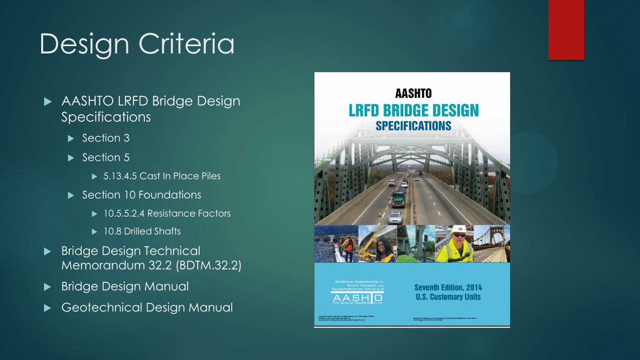
Design Criteria
AASHTO LRFD Bridge Design
Specifications
Section 3
Section 5
5.13.4.5 Cast In Place Piles
Section 10 Foundations
10.5.5.2.4 Resistance Factors
10.8 Drilled Shafts
Bridge Design Technical
Memorandum 32.2 (BDTM.32.2)
Bridge Design Manual
Geotechnical Design Manual
Design Manuals
FHWA-IF-99-025 FHWA-NHI-10-016
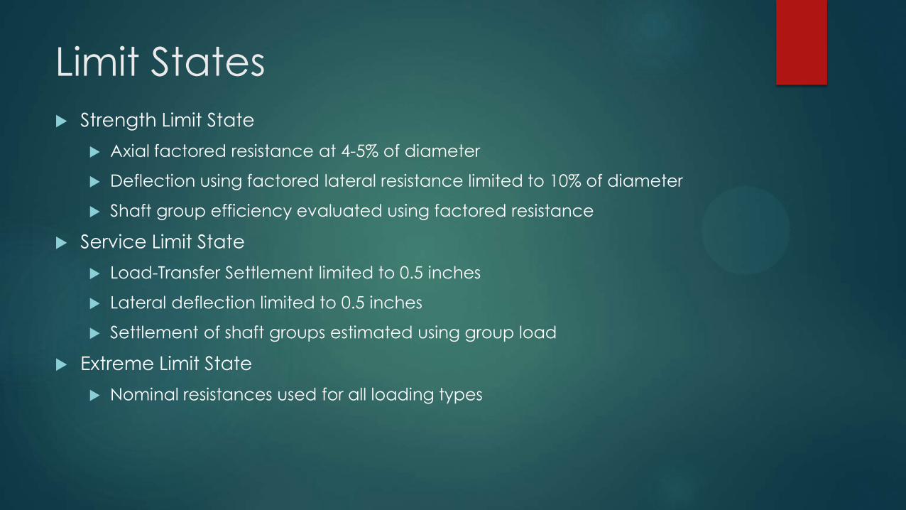
Limit States
Strength Limit State
Axial factored resistance at 4-5% of diameter
Deflection using factored lateral resistance limited to 10% of diameter
Shaft group efficiency evaluated using factored resistance
Service Limit State
Load-Transfer Settlement limited to 0.5 inches
Lateral deflection limited to 0.5 inches
Settlement of shaft groups estimated using group load
Extreme Limit State
Nominal resistances used for all loading types
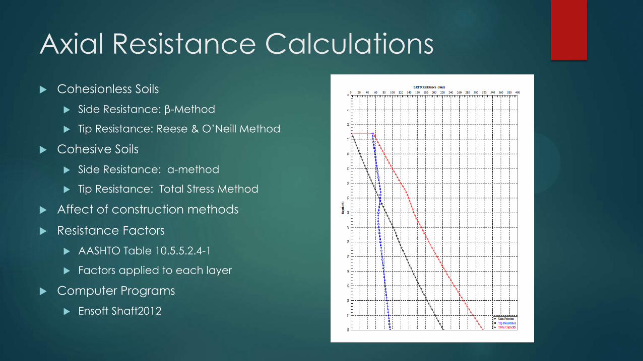
Axial Resistance Calculations
Cohesionless Soils
Side Resistance: β-Method
Tip Resistance: Reese & O’Neill Method
Cohesive Soils
Side Resistance: α-method
Tip Resistance: Total Stress Method
Affect of construction methods
Resistance Factors
AASHTO Table 10.5.5.2.4-1
Factors applied to each layer
Computer Programs
Ensoft Shaft2012
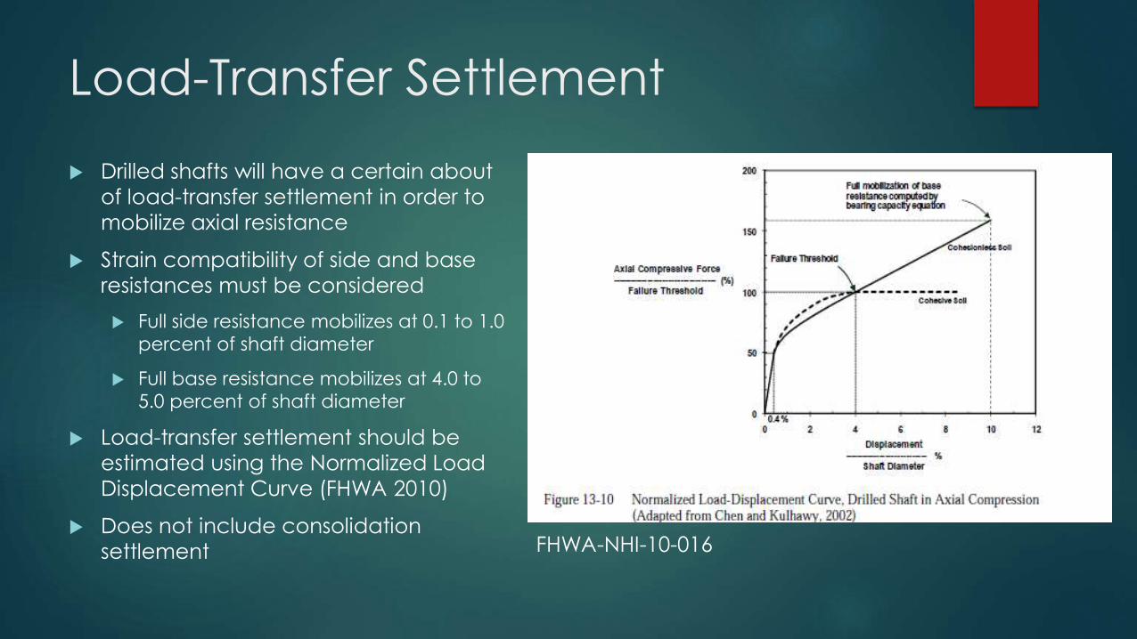
Load-Transfer Settlement
Drilled shafts will have a certain about
of load-transfer settlement in order to
mobilize axial resistance
Strain compatibility of side and base
resistances must be considered
Full side resistance mobilizes at 0.1 to 1.0
percent of shaft diameter
Full base resistance mobilizes at 4.0 to
5.0 percent of shaft diameter
Load-transfer settlement should be
estimated using the Normalized Load
Displacement Curve (FHWA 2010)
Does not include consolidation
settlement
FHWA-NHI-10-016
Lateral Resistance
Analysis performed using p-y curve analysis
AASHTO recommends a resistance factor of 1.0 for geotechnical lateral resistance
FHWA Drilled Shaft Manual recommends resistance factor of 0.67 for
geotechnical resistance.
For strength limit state apply resistance factors of
Φ=0.67 used to perform “push over” analysis
Φ=1.0 used to determine maximum shear and bending moment
Estimate lateral deflection at service limit state using nominal resistance
Computer Software
Ensoft LPile2013
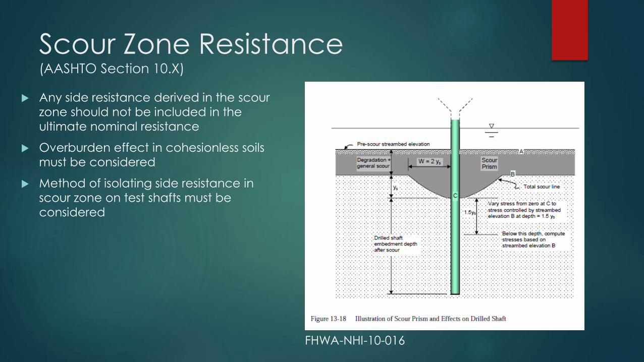
Scour Zone Resistance (AASHTO Section 10.X)
Any side resistance derived in the scour
zone should not be included in the
ultimate nominal resistance
Overburden effect in cohesionless soils
must be considered
Method of isolating side resistance in
scour zone on test shafts must be
considered
FHWA-NHI-10-016
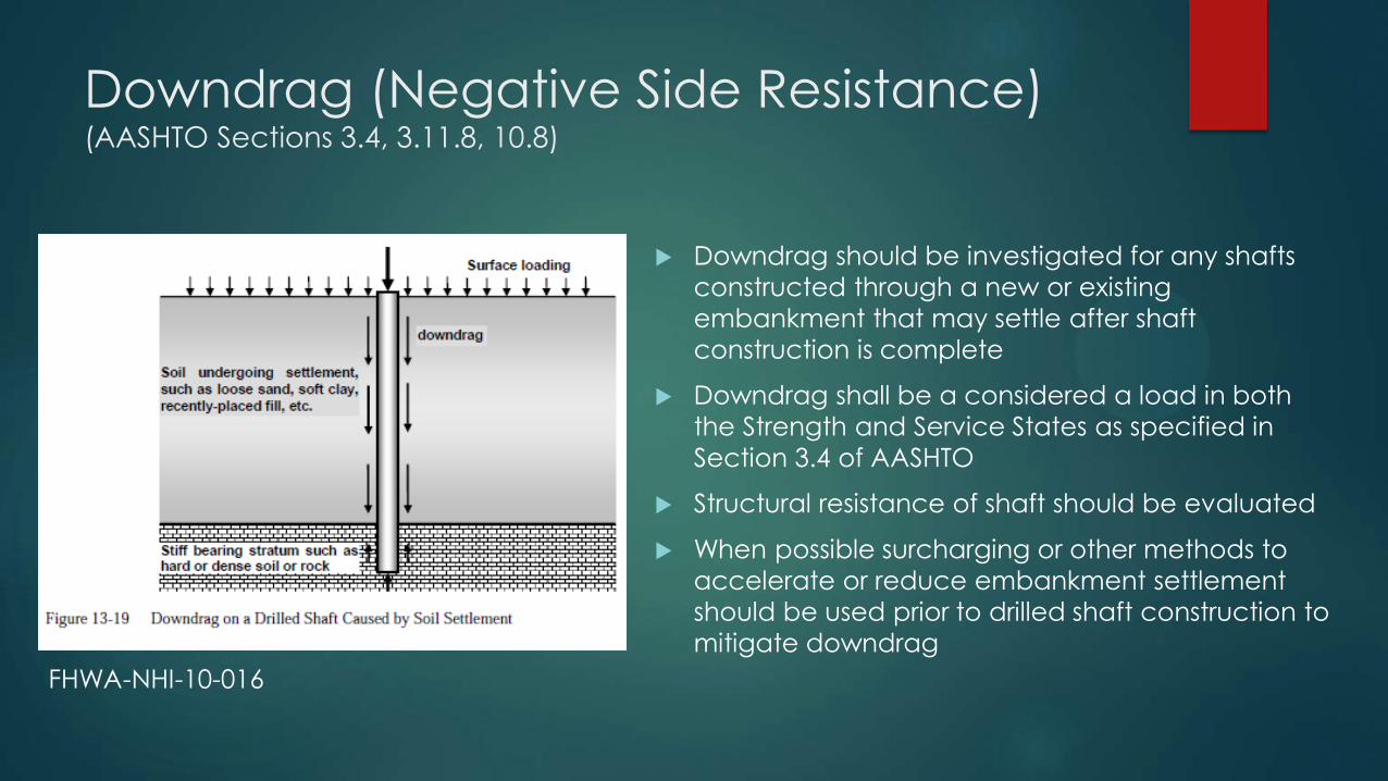
Downdrag (Negative Side Resistance) (AASHTO Sections 3.4, 3.11.8, 10.8)
Downdrag should be investigated for any shafts
constructed through a new or existing
embankment that may settle after shaft
construction is complete
Downdrag shall be a considered a load in both
the Strength and Service States as specified in
Section 3.4 of AASHTO
Structural resistance of shaft should be evaluated
When possible surcharging or other methods to
accelerate or reduce embankment settlement
should be used prior to drilled shaft construction to
mitigate downdrag
FHWA-NHI-10-016
Test Shaft and Load Testing
Test shafts allow for higher resistance factors than static calculations
Resistance factor is dependent on type of test
Although load testing is typically performed during the construction
phase of a project, the designer should be involved with reviewing the test set-up and results to determine production shaft lengths
Three Types of load test have been commonly used
Static
Bi-Directional (O-Cell®)
High-Strain Dynamic
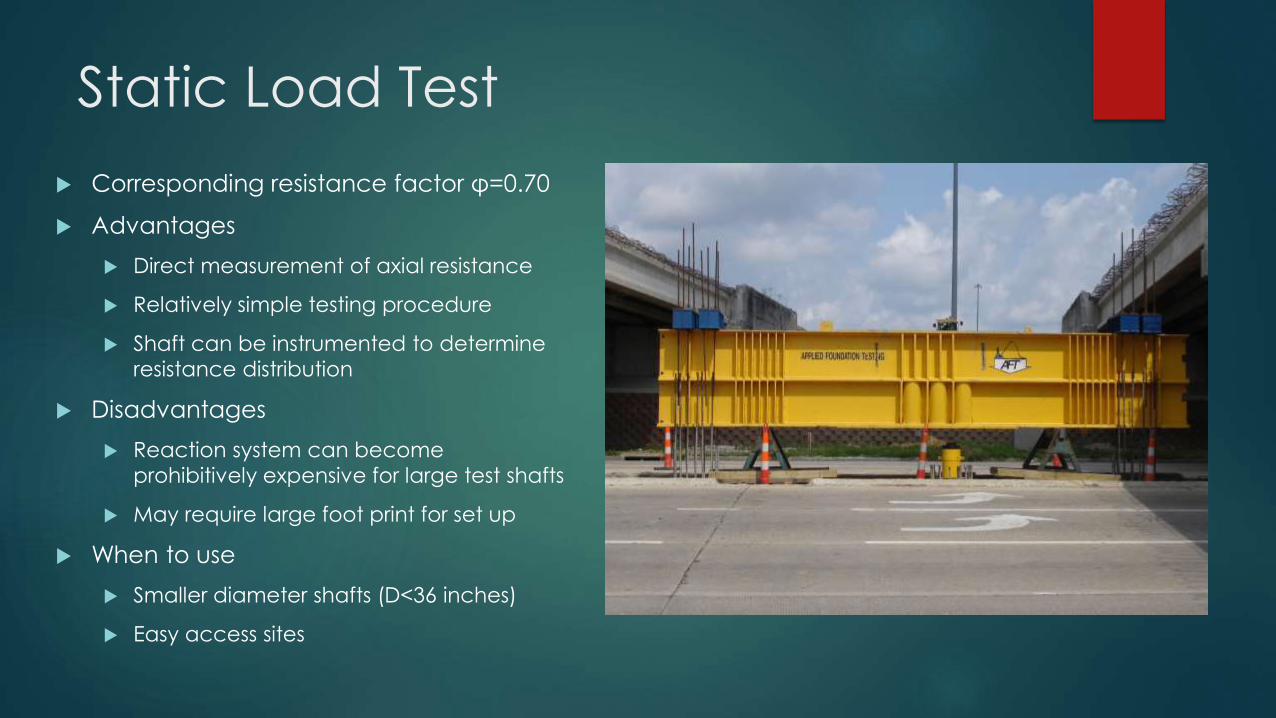
Static Load Test
Corresponding resistance factor φ=0.70
Advantages
Direct measurement of axial resistance
Relatively simple testing procedure
Shaft can be instrumented to determine
resistance distribution
Disadvantages
Reaction system can become
prohibitively expensive for large test shafts
May require large foot print for set up
When to use
Smaller diameter shafts (D<36 inches)
Easy access sites
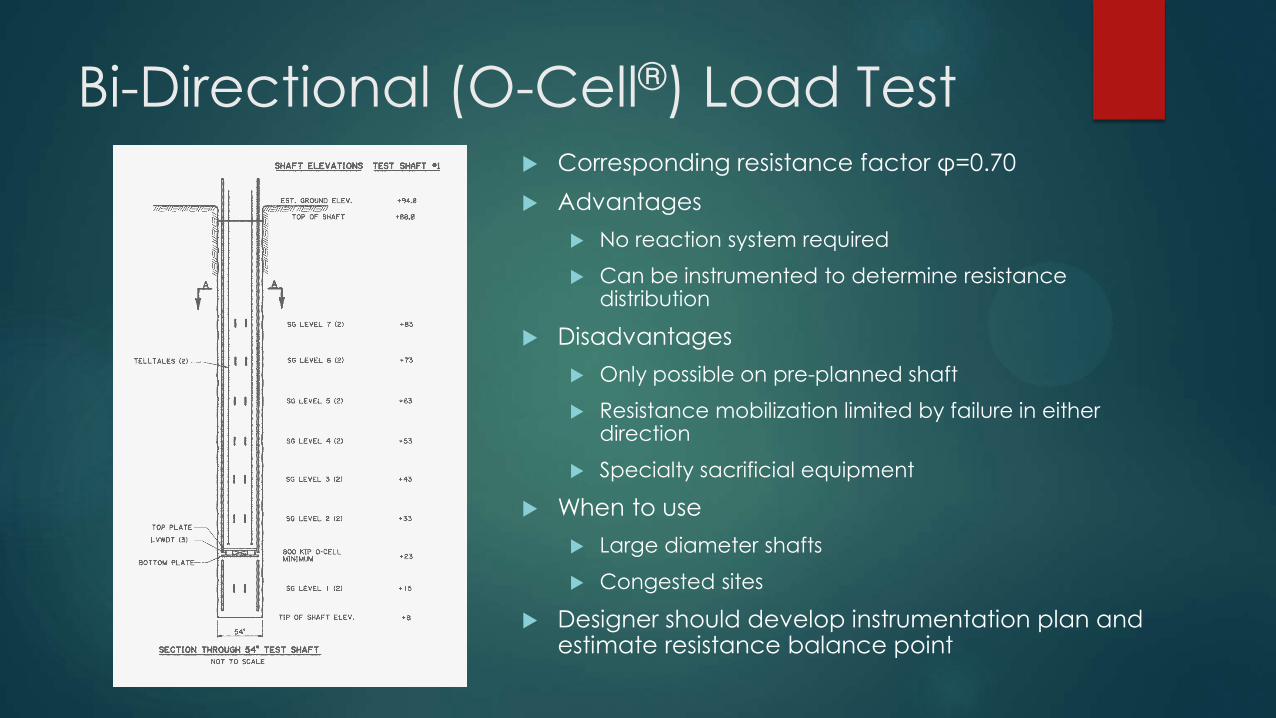
Bi-Directional (O-Cell®) Load Test Corresponding resistance factor φ=0.70
Advantages
No reaction system required
Can be instrumented to determine resistance distribution
Disadvantages
Only possible on pre-planned shaft
Resistance mobilization limited by failure in either direction
Specialty sacrificial equipment
When to use
Large diameter shafts
Congested sites
Designer should develop instrumentation plan and estimate resistance balance point
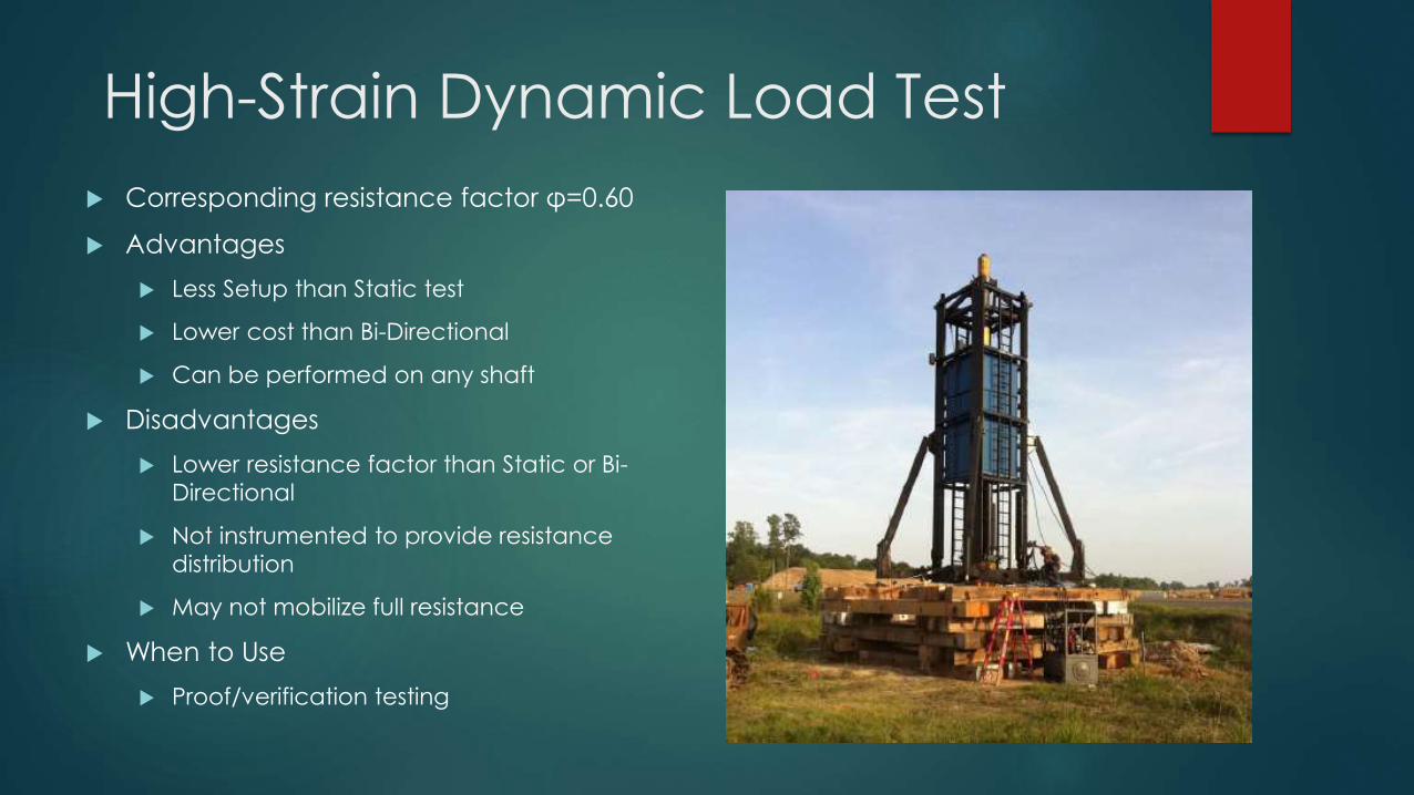
High-Strain Dynamic Load Test
Corresponding resistance factor φ=0.60
Advantages
Less Setup than Static test
Lower cost than Bi-Directional
Can be performed on any shaft
Disadvantages
Lower resistance factor than Static or Bi-
Directional
Not instrumented to provide resistance
distribution
May not mobilize full resistance
When to Use
Proof/verification testing
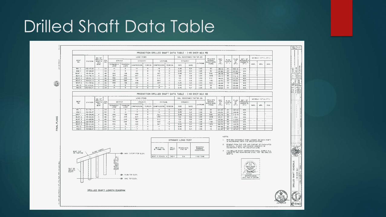
Drilled Shaft Data Table
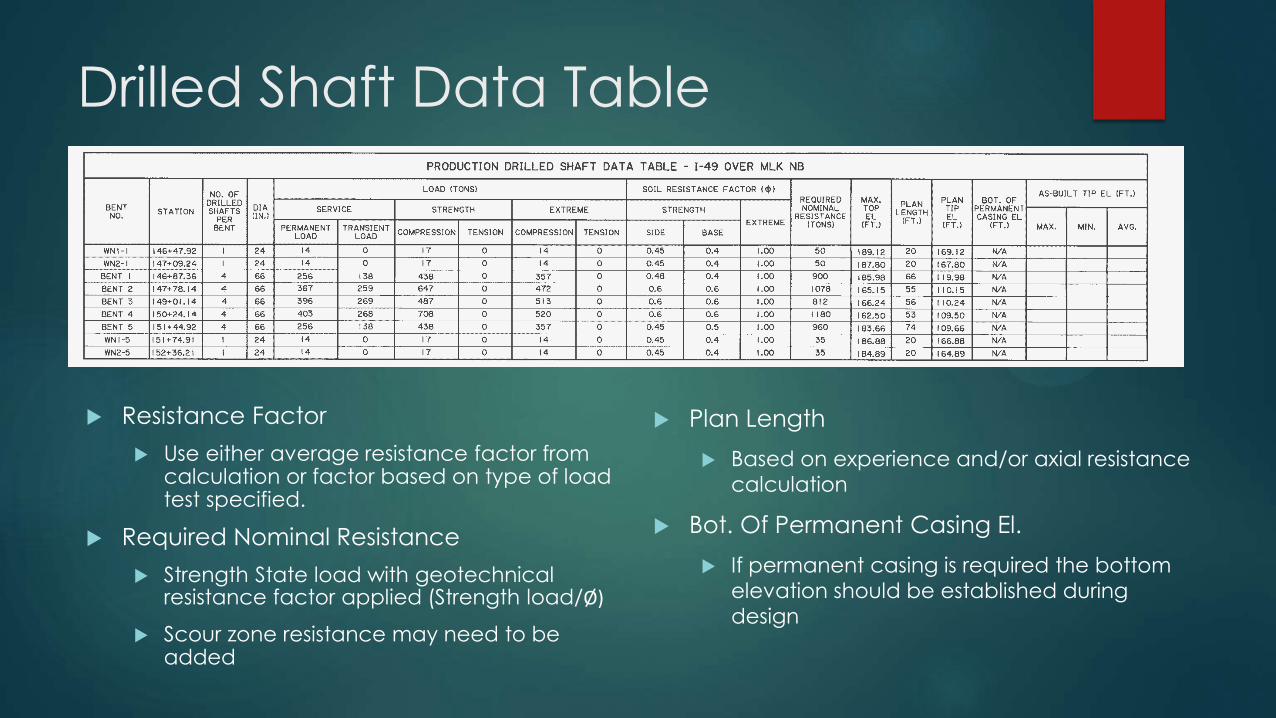
Drilled Shaft Data Table
Resistance Factor
Use either average resistance factor from calculation or factor based on type of load test specified.
Required Nominal Resistance
Strength State load with geotechnical resistance factor applied (Strength load/Ø)
Scour zone resistance may need to be added
Plan Length
Based on experience and/or axial resistance
calculation
Bot. Of Permanent Casing El.
If permanent casing is required the bottom
elevation should be established during
design

Other Design Considerations Rebar Details (AASHTO 5.13.4.5)
All rebar In drilled shaft must have a clear spacing of 5 inches
Rebar conflicts typically occur at the top of the shaft when columns use a Type II connection.
If dowel cage cannot not meet spacing requirements the following options should be considered
Require construction joint at bottom of splice zone to allow for
dry construction after completing shaft
Use of self-consolidating concrete (SCC) mix instead of class S
Trial/Technique Shaft
Used to verify Contractor’s construction method
Can be combined with test shaft
Permanent Casing
Primarily required for shafts constructed over water or near existing foundations and rail crossings
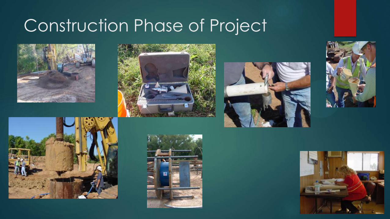
Construction Phase of Project
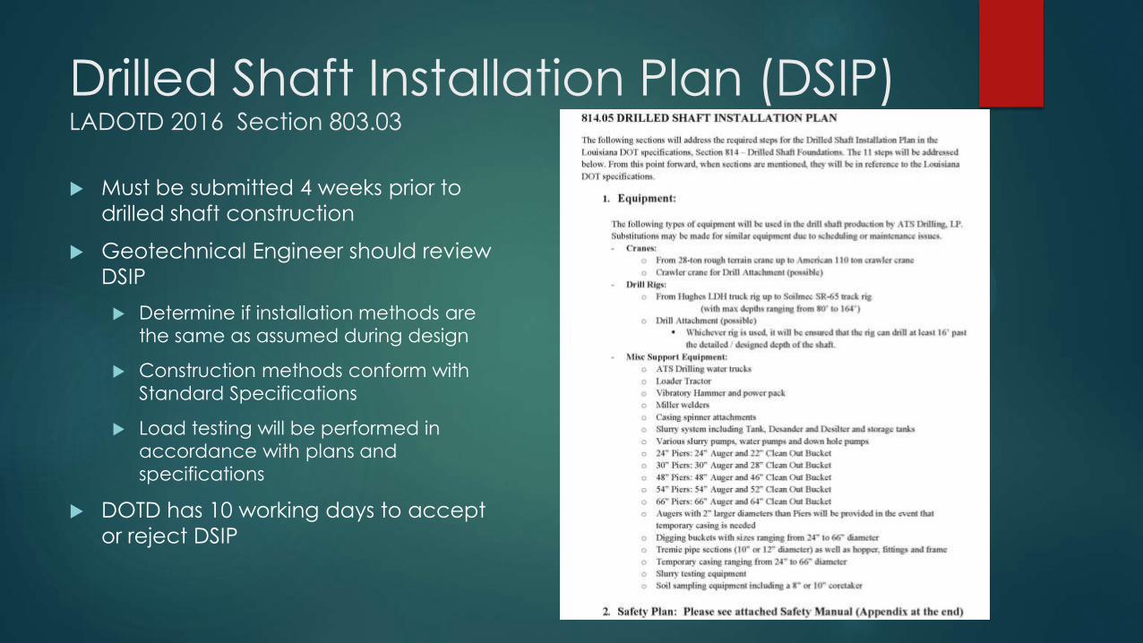
Drilled Shaft Installation Plan (DSIP) LADOTD 2016 Section 803.03
Must be submitted 4 weeks prior to
drilled shaft construction
Geotechnical Engineer should review
DSIP
Determine if installation methods are
the same as assumed during design
Construction methods conform with
Standard Specifications
Load testing will be performed in
accordance with plans and
specifications
DOTD has 10 working days to accept
or reject DSIP
Drilled Shaft Preconstruction Conference LADOTD 2016 Section 803.04
Required a minimum of 7 days prior to shaft construction
Attendees should include representative from
DOTD Construction
Geotechnical Designer
Drilled Shaft Subcontractor
General Contractor
The DSIP should be approved prior to meeting
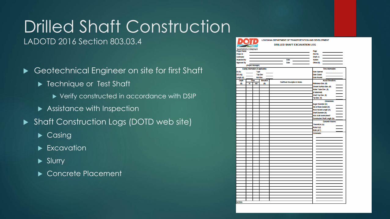
Drilled Shaft Construction LADOTD 2016 Section 803.03.4
Geotechnical Engineer on site for first Shaft
Technique or Test Shaft
Verify constructed in accordance with DSIP
Assistance with Inspection
Shaft Construction Logs (DOTD web site)
Casing
Excavation
Slurry
Concrete Placement
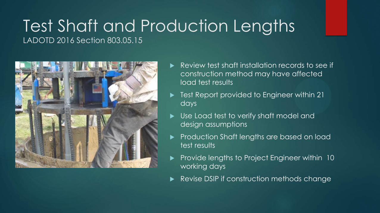
Test Shaft and Production Lengths LADOTD 2016 Section 803.05.15
Review test shaft installation records to see if
construction method may have affected
load test results
Test Report provided to Engineer within 21
days
Use Load test to verify shaft model and
design assumptions
Production Shaft lengths are based on load
test results
Provide lengths to Project Engineer within 10
working days
Revise DSIP if construction methods change
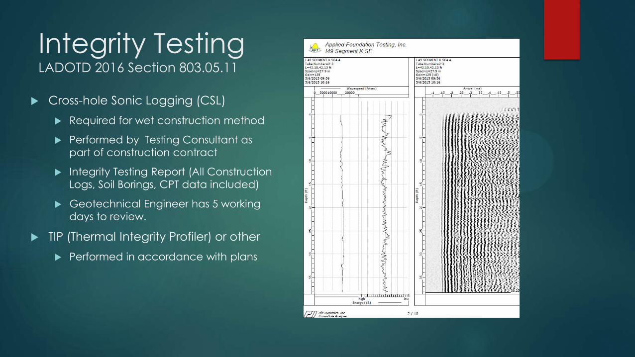
Integrity Testing LADOTD 2016 Section 803.05.11
Cross-hole Sonic Logging (CSL)
Required for wet construction method
Performed by Testing Consultant as
part of construction contract
Integrity Testing Report (All Construction
Logs, Soil Borings, CPT data included)
Geotechnical Engineer has 5 working
days to review.
TIP (Thermal Integrity Profiler) or other
Performed in accordance with plans
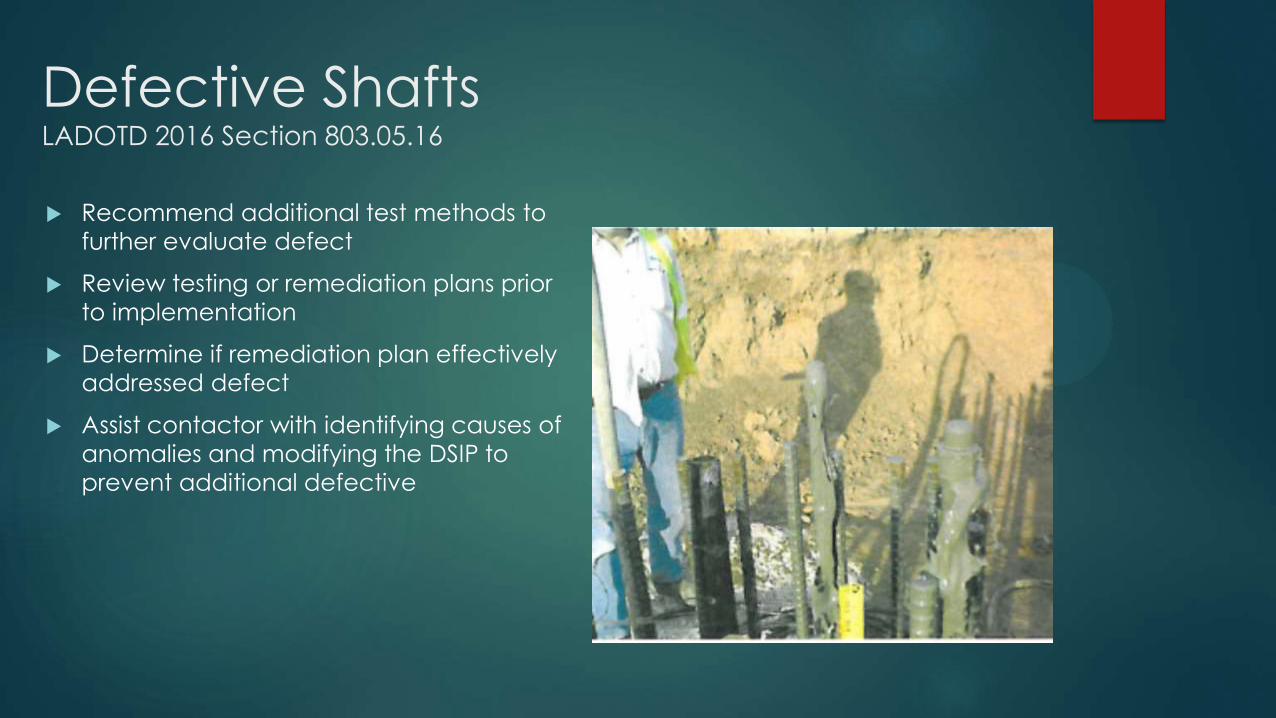
Defective Shafts LADOTD 2016 Section 803.05.16
Recommend additional test methods to
further evaluate defect
Review testing or remediation plans prior
to implementation
Determine if remediation plan effectively
addressed defect
Assist contactor with identifying causes of
anomalies and modifying the DSIP to
prevent additional defective
2016 Standard Specification
814 Drilled Shaft Foundations => 803 Drilled Shafts
Foundation Element Specifications Near Front of Part 8
Aligned with AASHTO Bridge Design and Construction
Specifications
Drilled Shaft Preconstruction Conference
2016 Specification
Construction Log forms to be provided
Trial Shaft is now Technique Shaft
Separated Payment of CSL From Load Test
Load Test Items are standard items
Static Load Test (Conform to ASTM D1143, Procedure A: Quick Test)
High-Strain Dynamic (ASTM D4945 )
Force Pulse (Rapid) Load Test (ASTM D7383)
Bi-Directional Load Cell Test (O-Cell)

Questions?