
LAC2006 Proceedings - ZKMlac.zkm.de/2006/papers/lac2006_proceedings.pdf · LAC2006 Proceedings ......
104
LAC2006 Proceedings 4th International Linux Audio Conference April 27 – 30, 2006 ZKM | Zentrum f¨ ur Kunst und Medientechnologie Karlsruhe, Germany
Transcript of LAC2006 Proceedings - ZKMlac.zkm.de/2006/papers/lac2006_proceedings.pdf · LAC2006 Proceedings ......

LAC2006 Proceedings
4th International Linux Audio Conference
April 27 – 30, 2006
ZKM | Zentrum fur Kunst und Medientechnologie
Karlsruhe, Germany

Published byZKM | Zentrum fur Kunst und Medientechnologie
Karlsruhe, GermanyApril, 2006
All copyrights remain with the authorswww.zkm.de/lac/2006
Contents
Thursday, April 27, 2006 – Lecture Hall
12:00 AM Fons Adriaensen
Acoustical Impulse Response Measurement with ALIKI . . . . . . . . . . . . . . . . . . . . . . . . 9
02:00 PM Arthur Clay, Thomas Frey and Jurg Gutknecht
Unbounded: Aos & The GoingPublik Software . . . . . . . . . . . . . . . . . . . . . . . . . . . . . . . . 15
03:00 PM Lee Revell
Realtime Audio vs. Linux 2.6 . . . . . . . . . . . . . . . . . . . . . . . . . . . . . . . . . . . . . . . . . . . . . . . . . 21
04:00 PM Asbjørn Sæbø and Peter Svensson
A Low-Latency Full-Duplex Audio over IP Streamer . . . . . . . . . . . . . . . . . . . . . . . . . . 25
05:00 PM Marije Baalman
swonder3Dq: software for auralisation of 3D objects with Wave Field Synthesis 33
Friday, April 28, 2006 – Lecture Hall
11:00 AM Yann Orlarey, Albert Graf and Stefan Kersten
DSP Programming with Faust, Q and SuperCollider . . . . . . . . . . . . . . . . . . . . . . . . . . 39
Saturday, April 29, 2006 – Lecture Hall
11:00 AM Fons Adriaensen
Design of a Convolution Engine optimised for Reverb . . . . . . . . . . . . . . . . . . . . . . . . . 49
12:00 AM Josh Green
Sampled Waveforms And Musical Instruments . . . . . . . . . . . . . . . . . . . . . . . . . . . . . . . . 55
02:00 PM Frank Barknecht
128 Is Not Enough - Data Structures in Pure Data . . . . . . . . . . . . . . . . . . . . . . . . . . . . 61
03:00 PM Eric Lyon
A Sample Accurate Triggering System for Pd and Max/MSP . . . . . . . . . . . . . . . . . . 67
04:00 PM Victor Lazzarini
Scripting Csound 5 . . . . . . . . . . . . . . . . . . . . . . . . . . . . . . . . . . . . . . . . . . . . . . . . . . . . . . . . . . . .73
05:00 PM Hartmut Noack
Linux and music out of the box . . . . . . . . . . . . . . . . . . . . . . . . . . . . . . . . . . . . . . . . . . . . . . . 79
LAC20063
Saturday, April 29, 2006 – Media Theatre
03:00 PM Daniel James and Free Ekanayaka
64 Studio - creative and native . . . . . . . . . . . . . . . . . . . . . . . . . . . . . . . . . . . . . . . . . . . . . . . . 85
Sunday, April 30, 2006 – Lecture Hall
12:00 AM Martin Rumori
footils. Using the foo Sound Synthesis System as an Audio Scripting Language 91
14:00 AM Jurgen Reuter
Ontological Processing of Sound Resources . . . . . . . . . . . . . . . . . . . . . . . . . . . . . . . . . . . . 97
LAC20064
Preface
Being the fourth of its kind, the International Linux Audio Conference 2006 is onceagain taking place at the ZKM | Institute for Music and Acoustics in Karlsruhe,Germany. By now the conference has become an established event and is worthbeing marked in calendars early.
We are very happy about the ongoing interest and devotion of our participantsand guests. This allows us to offer a wide range of different programme entries—presentations, lectures, demos, workshops, concerts and more.
As with the last conference all submitted papers have again undergone a reviewprocess. At least two independent experts have read and commented on each pa-per, and their feedback was used by the submitters to further improve on the clarityand correctness of their work. This has once again resulted in what we think is afine selection of currently ongoing developments in the Linux/Audio software scene.
As each year, we want to thank everyone who has participated in bringing thisLAC2006 conference to life—authors, composers, reviewers, helpers and anyone wemay have forgotten—and we wish everyone a pleasant and enjoyable stay at theZKM and in Karlsruhe.
Gotz Dipper and Frank NeumannOrganization Team LAC2006
Karlsruhe, April 2006
The International Linux Audio Conference 2006 is supported by
LAC20065

Organization Team LAC2006
Gotz Dipper ZKM | Institute for Music and AcousticsFrank Neumann LADMarc Riedel ZKM | Institute for Music and Acoustics
ZKM
Peter Weibel CEO
Jurgen Betker Graphic ArtistHartmut Bruckner Sound EngineerLudger Brummer Head of the Institute for Music and AcousticsTobias Ehni Event ManagementUwe Faber Head of the IT DepartmentHans Gass Technical AssistantJoachim Goßmann TonmeisterGabi Gregolec Event ManagementAchim Heidenreich Project DevelopmentMartin Herold Technical AssistantMartin Knotzele Technical AssistantAndreas Lieflander Coordination, Technical AssistantPhilipp Mattner Technical AssistantAlexandra Mossner Assistant of ManagementCaro Mossner Event ManagementChandrasekhar Ramakrish-nan
Software Developer
Thomas Saur Sound EngineerJoachim Schutze IT DepartmentAnatol Serexhe Technical AssistantBerthold Schwarz Technical AssistantBernhard Sturm Production EngineerManuel Weber Technical Director of the Event DepartmentMonika Weimer Event ManagementSusanne Wurmnest Event Management
LAD
Jorn Nettingsmeier Essen, GermanyEric Dantan Rzewnicki Radio Free Asia, Washington
LAC20066

Reviewers
Fons Adriaensen Alcatel Space, Antwerp/BelgiumFrank Barknecht Deutschlandradio, Koln/GermanyIvica Ico Bukvic University of Cincinnati, Ohio/USAPaul Davis Linux Audio Systems, Pennsylvania/USAGotz Dipper ZKM Karlsruhe/GermanyTakashi Iwai SUSE Linux Products GmbH, Nurnberg/GermanyDaniel James 64 Studio Ltd./UKVictor Lazzarini National University of Ireland, MaynoothFernando Lopez-Lezcano CCRMA/Stanford University, California/USAJorn Nettingsmeier Essen/GermanyFrank Neumann Karlsruhe/GermanyDave Phillips Findlay, Ohio/USA
LAC20067

LAC20068

Acoustical Impulse Response Measurement with ALIKI
Fons [email protected]
AbstractThe Impulse Response of an acoustical space canbe used for emulation of that space using a con-volution reverb, for room correction, or to obtaina number of measures representative of the room’sacoustical qualities. Provided the user has accessto the required transducers, an IR measurement canbe performed using a standard PC equipped with agood quality audio interface. This paper introducesa Linux application designed for this task. The the-oretical background of the method used is discussed,along with a short introduction to the estimatedmeasures. A short presentation of the program’s fea-tures is also included.
KeywordsAcoustics, impulse response, convolution, reverb.
1 Introduction
Equipment for measuring the acoustical pa-rameters of an environment has traditionallybeen the realm of a small group of highly spe-cialised electronics manufacturers. During thelast decade, the ready availability of mobilecomputers and of high quality portable audiointerfaces has resulted in a move towards mainlysoftware based solutions.
Early programs just emulated the standard-ised (hardware based) procedures to measuree.g. reverb time. The computing power beingavailable today enables the use of other meth-ods, such as a direct measurement of a room’simpulse response, from which all interesting in-formation can be derived. Several methods tocapture impulse responses have been developed,and these will be discussed below.
It seems that very little free and Linux-basedsoftware is available for this task. The DigitalRoom Correction package from Denis Sbragion1 includes some scripts to perform an impulseresponse measurement. It is possible to obtainvery good results with these scripts, but theyare not easy to use.
1http://drc-fir.sourceforge.net
In the Windows based world, a number of so-lutions have been available for some time. Mostof these are based on the use of pseudo-randomsequences. The MLSSA system from DRA Lab-oratories 2 (requiring special hardware) was oneof the first using this method, and is well known.As an example of a package using more ad-vanced methods, the Aurora Plugins 3 from An-gelo Farina should be mentioned.
This paper introduces a new Linux based in-tegrated system 4 developed by the author, andavailable under the terms of the GPL. ALIKIwill capture impulse responses in up to eightchannels simultaneously. The recorded data canbe used directly for e.g. digital room correc-tion, edited and prepared for use in a convolu-tion based reverb, or used to compute acousticalparameters such as reverb time and various en-ergy ratios.
The following sections will describe the mea-surement and analysis methods used in this soft-ware.
2 IR measurement methods
The impulse response (IR) of a system is theoutput signal it produces for an input consist-ing of a single Dirac pulse. The mathematicaldefinition of a Dirac pulse requires zero widthand unit energy, which is not possible in the realworld, so in practice finite-width impulses com-patible with the required bandwidth are used.In a sampled system in particular, the Dirac im-pulse is a signal consisting of one sample of unitamplitude followed by all zeros. It contains allfrequencies from zero to the Nyquist limit withequal energy and a known phase.
Provided the system is linear and time-invariant, the IR contains all information thereis about its behaviour, and permits the calcula-tion of the system’s response to any input signal.
2http://www.mlssa.com3http://farina.eng.unipr.it/aurora/home.htm4http://users.skynet.be/solaris/linuxaudio/aliki.html
LAC20069

ImpulseResponse
SignalGenerator
Deconvo- lution
B
ForwardFilter
InverseFilter
ImpulseResponse
DiracPulseA
Figure 1: IR measurement using filtered Dirac pulse. A: theoretical model, B: practical realization.
The main problem with using Dirac pulses inan acoustical measurement is that as a result oftheir very short duration and finite amplitude,they contain very little energy, and measure-ment accuracy will be limited by the signal tonoise ratio of the equipment used and of thesystem itself. While it is possible to use Diracpulses reproduced by a loudspeaker in the con-trolled environment of an acoustics laboratory,this is all but infeasible in most real life situa-tions, e.g. for measuring a room or concert hall,where there will always be background noises ofsome sort.
There are basically two ways to overcome thisdifficulty: either generate a high energy impulsedirectly as a sound, or find some method tospread the test signal over a longer time andto undo this operation after the measurement.
For the first approach, various methods havebeen used by acoustics engineers, ranging fromexploding balloons and starter’s pistols to veryexpensive special equipment to generate shorthigh amplitude sound pulses. While such meth-ods can be used e.g. to measure the reverb timeof a concert hall, they still require a very largedynamic range in the measurement system, andthey are not accurate and repeatable enough toobtain an IR to be used for room correction orfor a convolution reverb.
The second solution is based on the follow-ing idea. Suppose we have a filter H withcomplex frequency response H(ω). If the filterhas a non-zero gain at all frequencies, we canfind an inverse filter R with frequency responseR(ω) = z−n/H(ω). The z−n is a pure delayrequired to make such a filter causal and physi-cally realizable. Putting the two filters in series,only the (known) delay remains. Since the fil-ters are linear, and if we assume the same of thesystem to be measured, we can put the systemin between the two filters and obtain its impulse
response using the filtered signal instead of theDirac pulse (fig.1A).
Since we can regard any signal as the outputof an FIR filter having the signal’s sample val-ues as its coefficients, we could in theory use anysignal we want as long as the inverse filter existsand we can find some way to compute and im-plement it. For some classes of signals this canbe done relatively easily, and that is the basis ofthe two methods discussed in the next sections.In practice the theoretical model of fig.1A is re-alized by generating the signal directly insteadof filtering a Dirac pulse, and the inverse fil-tering is usually done by (de)convolution ratherthan a by real filter (fig.1B).
2.1 Maximum length binary sequencesPseudo random binary sequences can be gener-ated by a shift register with exclusive-or feed-back from selected taps. Provided the correctfeedback terms are used, a generator using Nstages will produce a maximum length sequence(MLS) of length L = 2N − 1. A sampled audiosignal derived from such a sequence has exactlythe same power spectrum as a Dirac pulse re-peated every L samples, but it has L times morepower for the same amplitude. For example,using an L = 1023 sequence will improve thesignal to noise ratio by 30 dB.
The inverse filtering for such a signal can bedone efficiently by using the Hadamard trans-form. Like for the Fourier transform, a ‘fast’version of this transform exists (and it is evensimpler than the FFT). This is the way theMLSSA software mentioned before (and manyother systems) operate.
For acoustical measurements, the signal canbe filtered further to obtain a ’pink’ spectruminstead of ’white’ noise, again improving theS/N ratio at low frequencies where it is usuallythe most problematic.
A more elaborate discussion of MLS based
LAC200610

techniques can be found in the references (Van-derkooy, 1994).
The main difficulty with the MLS method isits sensitivity to non-linear behaviour. Mostloudspeakers produce substantial amounts ofdistortion, and this will interfere with the mea-surement and show up as spurious signals in theimpulse response. The method discussed in thenext section, while more complex to implement,does not have this problem.
2.2 Swept sine techniquesA second class of signals for which the inversefilter can be computed easily are linear and log-arithmic frequency sweeps. For a linear sweep,the inverse is just the time reversal of the origi-nal signal. Such a signal has a ‘white’ spectrum,and for acoustical measurements a logarithmicsweep, having a ‘pink’ power spectrum is oftenpreferred. In that case, provided the sweep isnot too fast, the inverse filter is again the time-reversed original, but modified by a +6 dB peroctave gain factor (6 dB, and not 3, since a +3dB per octave correction applied to each filterseparately would make both of them, and theirproduct, ‘white’). In both cases the inverse filtercan be realized efficiently by using FFT-basedconvolution.
The advantage of using a sweep is that at anytime we produce only a single frequency, andany distortion introduced will consist of the har-monics of that frequency only. If we use a risingfrequency sweep, the harmonics will be gener-ated ahead of the same frequencies appearingin the signal. So after deconvolution, any dis-tortion will appear as spurious peaks in negativetime in the impulse response, and most of it canthen be edited out easily.
Another interesting feature of this method isthat it does not depend on exact synchronisa-tion of the playback and capture sample clocks.Any frequency error between these will resultin a ’smearing’ of the impulse response, in thesense that a Dirac pulse becomes itself a veryshort sweep. It is even possible to correct forthis after the deconvolution.
The sweep method was pioneered by AngeloFarina (Farina, 2000), and it is the one used inALIKI.
3 Measurements derived from theimpulse response
This section provides a quick overview of someacoustical measures that can be calculated froma captured impulse response.
If IR measurements are performed for use ina convolution reverb system, then the choice ofthe transducers used is largely a matter of com-mon sense combined with aesthetic preferences.The same is to some extent true if the object isroom correction.
In contrast, in order to derive the measuresdescribed below, the IR measurement must bedone according to a standardised procedure,and by using the correct equipment. In prac-tice this means the use of true omnidirectionalspeakers (purpose built), and in some cases of amicrophone calibrated for diffuse-field measure-ments (i.e. having a flat response integratedover all directions rather than on-axis).
The two ISO documents mentioned in theReferences section provide a good introductionto what is involved in such measurements.
All these values can be calculated for the fullfrequency range signal, for an A-weighted ver-sion, or octave or sub-octave bands.
3.1 The Schroeder integral
Most of the values described in the follow-ing sections can be obtained by computing theSchroeder integral of the IR, defined as follows.Let p(t) be the impulse response, with t = 0corresponding to the arrival of the direct sound.Then the Schroeder integral of p(t) is the func-tion
S(t) =∫ ∞
tp2(t)dt (1)
In other words, S(t) corresponds to the energystill remaining in the IR at time t. When plottedin dB relative to the maximum value at t =0, S(t) will be same as the level decay curveobtained after switching off a steady signal.
3.2 Reverb Time and Early DecayTime
The conventional definition of the Reverb Timeis the time required for the sound level to decayto -60 dB relative to the original level, after asteady signal (normally white or filtered noise)is switched off. This time is normally denotedRT60 if the S/N ratio permits a reliable mea-surement down to that level, or RT30 if it isextrapolated from the -30 dB time.
For a measurement derived from an IR, itcan be read directly from the Schroeder inte-gral. The ISO standard prescribes that RT30
should be derived from the times the integralreaches respectively -5 dB and -35 dB, obtainedby least-squares fitting, and extrapolated to the
LAC200611
60 dB range. The RT20 value is computed formthe -5 dB and -25 dB times in the same way.
The Early Decay Time EDT is similar butderived from the -10 dB point of the integral,again by least-squares fitting.
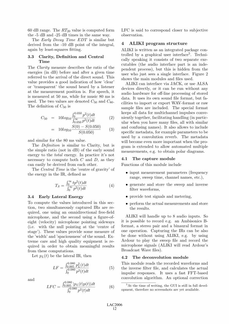
3.3 Clarity, Definition and CentralTime
The Clarity measure describes the ratio of theenergies (in dB) before and after a given timereferred to the arrival of the direct sound. Thisvalue provides a good indication of how ’clear’or ’transparent’ the sound heard by a listenerat the measurement position is. For speech, itis measured at 50 ms, while for music 80 ms isused. The two values are denoted C50 and C80.The definition of C50 is
C50 = 10log10
∫ 0.0500 p2(t)dt∫∞0.050 p2(t)dt
(2)
= 10log10S(0) − S(0.050)
S(0.050)(3)
and similar for the 80 ms value.The Definition is similar to Clarity, but is
the simple ratio (not in dB) of the early soundenergy to the total energy. In practice it’s notnecessary to compute both C and D, as theycan easily be derived from each other.
The Central Time is the ’centre of gravity’ ofthe energy in the IR, defined as
TS =∫∞0 tp2(t)dt∫∞0 p2(t)dt
(4)
3.4 Early Lateral EnergyTo compute the values introduced in this sec-tion, two simultaneously captured IRs are re-quired, one using an omnidirectional free-fieldmicrophone, and the second using a figure-of-eight (velocity) microphone pointing sideways(i.e. with the null pointing at the ‘centre ofstage’). These values provide some measure ofthe ’width’ and ’spaciousness’ of the sound. Ex-treme care and high quality equipment is re-quired in order to obtain meaningful resultsfrom these computations.
Let pL(t) be the lateral IR, then
LF =∫ 0.0800.005 p2
L(t)dt∫ 0.0800 p2(t)dt
(5)
and
LFC =∫ 0.0800.005 |pL(t)p(t)|dt∫ 0.080
0 p2(t)dt(6)
LFC is said to correspond closer to subjectiveobservation.
4 ALIKI program structure
ALIKI is written as an integrated package con-trolled by a graphical user interface5. Techni-cally speaking it consists of two separate exe-cutables (the audio interface part is an inde-pendent process), but this is hidden from theuser who just sees a single interface. Figure 2shows the main modules and files used.
ALIKI can interface via JACK, or use ALSAdevices directly, or it can be run without anyaudio hardware for off-line processing of storeddata. It uses its own sound file format, but fa-cilities to import or export WAV-format or rawsample files are included. The special formatkeeps all data for multichannel impulses conve-niently together, facilitating handling (in partic-ular when you have many files, all with similarand confusing names). It also allows to includespecific metadata, for example parameters to beused by a convolution reverb. The metadatawill become even more important when the pro-gram is extended to allow automated multiplemeasurements, e.g. to obtain polar diagrams.
4.1 The capture moduleFunctions of this module include
• input measurement parameters (frequencyrange, sweep time, channel names, etc.),
• generate and store the sweep and inversefilter waveforms,
• provide test signals and metering,
• perform the actual measurements and storethe results.
ALIKI will handle up to 8 audio inputs. Soit is possible to record e.g. an Ambisonics B-format, a stereo pair and a binaural format inone operation. Capturing the IRs can be alsobe done without using ALIKI, e.g. by usingArdour to play the sweep file and record themicrophone signals (ALIKI will read Ardour’sBroadcast Wave files).
4.2 The deconvolution moduleThis module reads the recorded waveforms andthe inverse filter file, and calculates the actualimpulse responses. It uses a fast FFT-basedconvolution algorithm. An optional correction
5At the time of writing, the GUI is still in full devel-opment, therefore no screenshots are yet available.
LAC200612

sweep
inverse
Capture
...
capture n
capture 1
plots resultscorrection
...raw IR 1
raw IR n
...edited IR 1
edited IR n
Schroederintegration
Measureestimation
A-weight
Octavebands
ImpulseeditorDeconvolution
ALSAJACK
session
Figure 2: ALIKI program structure and files
filter compensating for the response of the loud-speaker and/or microphone can be used.
The results are saved to the raw impulse re-sponse files, and transferred to the editor mod-ule.
4.3 The editor module
This provides visualisation and basic editing ofimpulse responses. It is used to
• normalise the IR to a standard level,
• calibrate the time axis (i.e. put the directsound at t = 0),
• trim the end of the IR to remove noise,
• remove the direct sound if required.
The editor will operate on groups of impulseresponses (e.g. a stereo pair or B-format) pre-serving relative timing and levels. Edited IRscan be saved for later use. Unless the user re-ally wants it, the editor will never overwrite theoriginal waveforms.
This module has one additional function: thefirst few milliseconds of an IR can be used tocompute an inverse FIR filter (up to 4096 taps)that will be used by the deconvolution engineto compensate for the response of the speakerand microphone. It uses a simple FFT-basedinversion method, and an interactive proceduresteered by the user in order to avoid major er-rors that could result from a simple automatedcalculation.
4.4 The filter, integration and measuremodules
The remaining modules in fig.2 are closely inte-grated from the user’s point of view.
The Schroeder integral can be computed andvisualised for the filtered or full-range IRs. A-weighing and octave band filtering is againperformed using FFT-base convolution, and iscombined with the backwards integration. Theintegrals are stored with a resolution of about1 millisecond. They can be exported in a for-mat readable by applications such as Gnuplot,which can convert them to a number of graphi-cal formats.
The first release of ALIKI computes EDT ,RT20, RT30, RTuser, TS , C50,80,user, D50,80,user,LF and LFC. Others (such as IACC) maybeadded in future versions.
All measured values can be exported as text,CSV, or Latex table format for use in spread-sheets or reports.
5 Acknowledgements
The IR measurement method used by ALIKIis based on the work of Prof. Angelo Farina(Dipartimento Ingegneria Industriale, Univer-sity of Parma, Italy). His many papers (freelyavailable via his website 6) are required readingfor anyone exploring the subject of acousticalIR measurement, in particular in the context ofsurround sound.
Also the work of Anders Torger (author ofBruteFir 7) and Denis Sbragion (author of
6http://pcfarina.eng.unipr.it7http://www.ludd.luth.se/ torger/brutefir.html
LAC200613

DRC) has been very inspiring.
References
Angelo Farina. 2000. Simultanuous measure-ment of impulse response and distortion witha swept-sine technique. Audio EngineeringSociety Preprint 5093.
ISO TC43/SC2. 2003. Acoustics — Measure-ment of the reverberation time — Part 1:Performance spaces. ISO CD 3382-1.
ISO TC43/SC2. 2004. Acoustics — Applica-tion of new measurement methods in buildingacoustics. ISO WD 18233.
John Vanderkooy. 1994. Aspects of MLS mea-suring systems. Journal of the Audio Engi-neering Society, 42(4):219–231.
LAC200614

Unbounded: Aos & The GoingPublik Software
Arthur Clay Dept. of Computer Science
Clausiusstrasse 59, CH-8092 Zurich, Switzerland
Thomas Frey, Dr. Dept. of Computer Science
Clausiusstrasse 59, CH-8092 Zurich, Switzerland [email protected]
Jürg Gutknecht, Dr. Prof. Dept. of Computer Science
Clausiusstrasse 59, CH-8092 Zurich, Switzerland jü[email protected]
ABSTRACT GoingPublik is a work for distributed ensemble and wearable computers. The core idea behind the work is a strategy of mo-bility employing a wearable computer system running a soft-ware based electronic scoring system. The score allows for ‘composed improvisation’, which permits improvisational ele-ments within a compositional structure. By electronically moni-toring the performer’s physical positions during performance using universal inputs such as geographical positions obtained via satellites and sensors using the earth’s magnetic field, the score makes suggestions to various degrees and times. This paper shows how electronic scoring can be self-regulating and depicts how performers using it are able to interact with one another and to create a unique choreographic dispersion of sound in space [1].
Keywords
Wearable Computers, Score Synthesis, HCIs, Aos, Bluebottle, Linux, Q-bic
1. INTRODUCTION In GoingPublik sonic coherency is accomplished through a theory of ‘distribution’. All of the electronic scoring systems used are matched and share similar sensor inputs, (3d-compass and GPS) which are the common denominator to virtually linked them. So despite the physical distribution, commonly shared elements can be structurally exploited. For example, at moments of close proximity between performers synchronized “tutti like” group movements such as rotation bring about syn-chronized changes in the score. The compositional quantities and qualities of the work are thereby based on spatial mobility; Intensity of form is held by changes in timbre and rhythmic modulations are brought about in conjunction with the sound distribution [2].
2. SOFTWARE & HARDWARE The system hardware in its current form comprises a Strong-ARM/XScale based proprietary wearable computer (Q-bic)[2]; a custom made micro programmed 3D compass sensor, a Gar-min GPS device, and a Micro Optical SV-6 head-mounted dis-play. The main tasks of the wearable computer is reading the sensor data and computing the score in real time according to predefined rules. The scoring application is programmed in a Pascal-like language called Active Oberon[4]. It runs on Blue-bottle (Aos)[5], a lean, open source system kernel enhanced by a highly efficient 2.5D graphics engine that supports sophisti-cated visual effects on the basis of general-purpose hardware.
3. BEYOND OPEN SOURCE
3.1 Open Sources and Useable Toolboxes Open source software is like an open toolbox. It is a necessary but often insufficient step towards truly "malleable" software. What is actually needed is mastery and full control of the tools in the box. ETH's integrated programming language Oberon has been available as open source since its invention. Oberon dif-fers from many comparable systems by its simplicity, minimal-ism and conceptual uniformity in the spirit of Niklaus Wirth's widely acknowledged lean-system tradition. The newest evolu-tion along this line is the Active Oberon language and runtime. As an innovation, Active Oberon introduces a new computing model based on interoperable objects with encapsulated active behavior. This model is ideally suited for programming "the new media", and it easily scales up to distributed systems. This issue addresses the growing interest in the use of computers in the new arts in general and the quite apparent benefits of cus-tom software design in particular. Using the "Going Publik" project software as a proof of concept, we shall argue in favor of both application-aware runtime kernels and small ad-hoc languages as an effective alternative to widely spread graphic builders.
3.2 The Lean versus the Fat System The reusability of typical open source software is not guaran-teed by its openness alone. Even if all the source code that is needed to rebuild an application is provided, it is often very difficult to reuse parts of a project for new purposes. Even re-ducing the functionality of an open source system can be diffi-cult because of non-modular or inconsequent design. The C based programming languages typically used in open source projects does not encourage a clean modularization and can easily result in header-file incoherencies whose correlation can only be grasped after a long period of review. One could con-sider the Linux kernel as an example. Although its system is
Figure 1. Members of the ensemble in “distributed” and “huddle” formations. Each player is wearing a Q-bic
computer, sensor network and display glasses.
LAC200615

“open”, it is at the same time “closed”, because only few people are able to really contribute to its development (in fact, all changes in the Linux kernel are still made by the original author, Linus Torvalds). Of course, kernels are not simple top-ics and this is not really that different in the case of Aos. How-ever, in a lean and compact system like Aos there are simply fewer unnecessary pitfalls and time consuming debug sessions. To continue the comparison between Linux (a well know sys-tem) and Aos (a less known system) in order to better under-stand the points made above, one can state that the Linux de-velopment can profit largely from a massive amount of man-power and available tools, where as Aos is more limited in this regard. However, most of the tool chain used for Linux devel-opment would not be necessary or would have been much eas-ier to develop for a small and completely compile-time type safe programming language such as Active Oberon. Although the available Linux tools and the number of C oriented pro-grammers who are willing to program far outweigh the time lost on insufficiencies of the used programming language, there is still no progress in obtaining malleable and more coherent tools for the future. To improve code reusability and understandability, ETH fol-lows the lean system initiative. Lean systems have a well-designed, clear and modular structure based on a unifying set of concepts. Lean systems are teachable and therefore understand-able. With a deep understanding of a software layer, it becomes possible to adapt it to new needs or to only port or implement the needed parts that are essential in solving a given problem. Having the possibility of leaving out unneeded parts not only improves resource efficiency of a program, but also reduces the number of possible errors and potential exploits.
4. THE SOFTWARE
4.1 Modularity and Malleability Contained in the GoingPublik software package are eight mod-ules, which can be more or less included or excluded during runtime. The elements depicted in Fig.2. within the rectangle are the software components, the elements depicted to the left are the sensor systems, and the elements depicted to the right are those drawn into the screen areas of the display glasses. The GPS and the 3d Compass sensor are connected per Blue-tooth and are mounted as wearable sensors on the performer’s
clothing. The graphic elements drawn by the Info Viewer, the Matrix Viewer and the Icon Viewer modules are combined in the display glasses into a single score as depicted in Fig.3. To exemplify the system’s malleability: When the software module “Icon State Engine” is not needed for the performance version without the behavioral icons, then it would simple be left out of the software package1. The icons would not appear in the viewer and the other modules would not be affected in any way and would operate as expected.
5. THE MATRIX WINDOW
5.1 The Modulating Matrix The basis of the electronic score is a modulating matrix. The resolution of the matrix is determined by the performer’s posi-tion within the performance space, which is obtained via GPS satellites or generated by a GPS simulator. In either case, the received GPS string is parsed and given further as x, y value pairs that reference the position within a predefined area. By moving within this area, the performer influences the position of the matrix’s lines, therefore continuously adjusting the ‘reso-lution’ of it to parameterize sonic domains with frequency and time values. The ‘Range-Lines’ of the matrix move on the hori-zontal plane in relation to the North-South axis; the ‘Time-Lines’ move on the vertical plane in relation to the West-East axis. The Time-Lines move in contrary motion and modulate the spaces between the lines into equidistant and non-equidistant states. The ‘Conduction-Arm’ travels through the matrix from the left to facilitate score reading. The time taken by the Conduction-Arm to scan through the space between two Time-Lines is always a constant value in milliseconds (inde-pendent of the distance), but is dependent on walking speed measured in meters per minute. There are four discrete tempi: Rest, Relax, Work and Hurry. The speed of the Conduction-Arm therefore makes a quantitative difference in the amount of time the performers may ‘stay’ on an area of the score image.
The movement of the Range-Lines brings about equidistant 1 Such a malleable system could also be realized by a program
written in C, but its lack of modularization concepts on the language level would require more efforts of the programmer.
Figure 3. The Matrix Window: (A) Score Image, (B) TimeLines, (C) RangeLines, (D) Conducting Arm, (E)
IconBar, (F) GoIcons, (G) ModIcons, (H) StopIcons, (I) Timer, (J) TempoBar, (K) Tempo, (L) GPS x-Coordinate,
(M) GPS y-Coordinate, (N) Activity Graph.
Fig. 2. Depicted is a schematic showing the relation-ships between the sensor systems and the component
packages of the GP software.
LAC200616

spaces, which limit and expand the instrumental range based on changes of position within the space. When all Range-Lines are present, seven range spaces can be seen. The available ranges would then be as follows: Outside, Very Low, Low, Middle, High, Very High and Outside. Ranges are always kept in con-secutive order, the performers freely choosing the lowest initial range first and then continue upward from there. The perform-ers decide where the boundaries the instrumental ranges are and what is meant by ‘outside’ the instrument.
5.2 Directional Imaging There are four score images and each is assigned a direction. A discrete resolution of eight possible ‘headings’ is used and these values determine the score image. Single score images are ren-dered at the poles of the compass and superimpositions between these. The 3d-compass also measures ‘pitch’ and ‘roll’, whose values distort the score image to create ‘variations’. The larger the intensity of pitch and roll is, the greater the distortion of the score image is. The size of the displayed score image is de-pendent on walking activity. This is calculated using speed average over a given period of time. If the performer is ‘stand-ing’ more than ‘walking’, the image will enlarge up to 200%; if the performer is ‘walking’ more than ‘standing’, the image will shrink back to its original size. Variations in sound material therefore not only arise on account of the Conduction-Arm speed but also due to score image distortion and changes in size.
5.3 The Action Icons Three groups of three icons contained on the “icon bar” are used to suggest actions to the performer. The green ‘Go-Icon’ and the red ‘Stop-Icon’ groups suggest changes in walking speed, the time spent doing so, and a random component. Re-
lated performative actions are associated with each of the icons to artistically integrate changes in walking activity, regulate the tempo in general and to integrate the performer’s sonically into the environment.
Based on the rate of heading change, walking speed and a ran-dom component, the ‘Mod-Icons‘ suggest how the score is to be read by designating parameters of ‘style’. Here, eye movement through the matrix is confined by phrasing rules. These rules are PHRASE (the division of the matrix into units of material), PATH (the form of the curve used to read through the matrix) and PLAY (the degree of density in playing while reading through the matrix). By interpreting the score in this manner, contrapuntal differences between the performers are brought about, so that ‘sonic windowing’ is created through which un-occupied audio space and variation in voice density are guaran-teed.
6. THE MAPPING WINDOW
6.1 Performance Modes There are two software based performance modes: An ‘indoor’ mode is for closed spaces and an ‘outdoor’ mode for open spaces. The indoor mode relies on a route simulator and the outdoor mode relies on GPS satellite information to make changes to the matrix and icons. The software automatically switches between route simulator and GPS satellite information dependent on satellite reception so that a performance may take place in and between closed and open spaces. To use the route simulator, each player draws a predetermined route onto the provided map with a handheld mouse. When finished, the per-former presses the range button and switches back to the Ma-trix-Window.
6.2 Synchronization Types There are two types of synchronization exploited in the work: ‘local’ and ‘global’. Local synchronization is made possible by
Figure 5. The Icon Menu Bar. From left to right are three blank Go-Icons, the Mod-Icon for “Medium Playing Den-sity”, a blank Mod-Icon, the Mod-Icon for “Phrasing in Groups of Five”, a blank Stop-Icon, the Stop-Icon for
“Stop and Hide”, and lastly the Stop-Icon for “Sit Down”.
Figure 6. The Mapping Window: (A) Map Area, (B) Range Box, (C) Performer’s Route, (D) X-Bow Position Indicator, (E) InfoBar, (F) Path Selector Button, (G) Path Record But-ton, (H) Stop- Record Button, (I) Calculate Range Button,
(J) Store Route Button, (K) Direction Indicator, (L) Length Indicator.
Fig. 4. The 360° of Directional Imaging: Single score images are at the poles and complex images
are between these poles.
LAC200617

the 3d compass sensor data and takes place when performers are “huddled” and change heading, pitch and tilt readings to-gether, thus changing the score image at the same time and to the same degree. For an ‘inside’ performance the performers dismantle their instruments and spread the parts across the pe-formance space. This action emphasizes the effect of distribu-tion visually and creates a predetermined task that results in a predictable choreography of movements. The system sensors respond accordingly, and the electronic score changes in con-junction to all movements made as the performers re-assemble their instruments. Global synchronization is made possible via GPS and takes place via Conduction-Arm synchronization and when there is some form of coordination of routes between two or more performers. For an outside’ performance three routes, one for each of the performers, are roughly designated. The greater the distance between the performers, the more varied their scores will appear; the lesser the distance between them, the more similar their scores will appear. So, when the separa-tion between performers diminishes as they come to meet, their scores slowly grow in similarity until each score matrix is simi-lar [6]. As listener, a gradual morphing from individual to col-lective sound masses can easily be heard.
7. FURTURE WORK
7.1 GPS Time Mark Function In the next version of the GoingPublik software, the GPS Time Mark will be used to synch an on-board clock housed on the Q-bic computer. The GPS Time Mark arrives at the exact same moment for all of the performers of the distributed ensemble and this event makes it possible to synchronize the movement of the Conduction- Arms of all of the players. To employ it aesthetically as a compositional mechanism, the concept of “global synchronization” is used again as a uniting force. Each of the four tempi used in the scoring system are in ratio to one another: Tempo “Relax” is therefore 2 * Tempo “Rest”, Tempo “Work” is 3 * Tempo “Rest” and Tempo “Hurry” is 4 * Tempo “Rest”. The speed of the Conduction Line for the slowest tempo, “Rest” is used as the basis for determining the speeds of the other three tempi used in the score.
What by “page” is meant is the width of the score image. So a tempo is always in terms of how long it takes the Conduction-Line to get through one “page” of the score, One page is the therefore the time it takes for the Conduction-Line to transverse the entire score image. In this way all of the Conduction-Arms of all players stay synchronized and will always meet (after some number of pages) at the “beginning” of a score “page” just as certain polyrhythmic groupings meet at the initial beat they began at. This feature was tested outside of the GoingPub-lik in the work China Gates for gongs and GPS-Wrist Control-ler [7].
7.2 Collaborative Score The GoingPublik system allows for the unique opportunity for composers and performers to research the possibilities of col-laborative scores. Through changing the .xml file that is used to preset the software, it is possible to designate which score im-ages are to be loaded into the matrix. Having each of the play-ers or each member of a group of composers prepare a single score image for the system, would bring about a system score which would consist of four distinct scores, which would then “integrate” into a single whole via the system and who it works to parameterize and vary the score images during a perform-ance. This possibility of collaboration demonstrates how the GoingPublik software is not a single work, but system, which can be used to interpret a body of, works written for it and also how it might be used to research collaboration in general amongst performers and composers.
8. CONCLUSION The movements made by the ensemble players can be under-stood as choreographic patterns having an internal system of counter-point: ‘bundled movements’, or synchronized move-ments made together are analogue to polyphony in similar mo-tion and ‘free movement’ or non synchronized movement car-ried out in non-relationship to one another are analogue to con-trary motion. Therefore, a parallel can be drawn between the distribution amount of the performers and the degree of ‘disso-nance’ in terms of rhythmic and range discord existing between them. A slight comparison between Linux and Aos system software was drawn. The comparison did not point to the better system, but was intended to serve the purpose of proposing a focus on new paradigms of computer science, in order to develop lan-guages that lead to more malleable and understandable tools. As an innovation, the Active Oberon language was introduced as such a new computing model, which is based on interoperable objects with encapsulated active behavior. By using the Going-Publik project as a proof of concept, it was argued that this computing model is ideally suited for programming need in the arts, in that it was made quite apparent that custom software design in the new arts has become quite common as has the needed adaptability of the that software for further develop-ments of the same an new art works.
9. ACKNOWLEDGEMENT Our thanks to Prof. Dr. Paul Lukowicz (Q-bic), Stijn Ossevort (Belt Design), Dr. Tom Stricker (Consulting), Dr. Emil Zeller (ARM Aos Porting), Mazda Mortasawi (Additional Program-ming) and Dr. Dennis Majoe of MASC, London (Sensor Sys-tems).
Figure 7. The figure illustrates how the Conducting Line (here indicated in blue) can be synchronized in
relation to tempo for each of four players. LAC2006
18

10. REFERENCES [1] http://homepage.mac.com/arthurclay/FileSharing8.html
[2] Clay, A/Frey, T/Gutknecht, J 2005: GoingPublik: Using Real-time Global Score Synthesis, in: Proceedings NIME 2005, Vancouver, Canada.
[3] Amft, O/Lauffer, M/Ossevort, S/Macaluso, F/Lukowicz, P/Tröster, G 2004: Design of the QBIC Wearable Comput-ing Platform, in: Proceedings of the 15th IEEE Interna-tional Conference on Application-specific Systems, Archi-tectures and Processors, Galveston (Texas).
[4] Muller, P 2002: The Active Object System - Design and Multiprocessor Implementation. PhD thesis, Institute for Computer Systems, ETH Zurich.
[5] http://www.bluebottle.ethz.ch/
[6] Clay, A/Frey, T/Gutknecht, J 2004: GoingPublik: Going-Publik: Suggesting Creativity Inside the Ivory Tower, in: Proceedings C&C 2004, London
[7] Clay, A/Majoe D 2006: China Gates: A Work in Progress, in Proceedings 3rd International Mobile Muisc Workshop, Brighton England
[8] Martinsen, F 2004: Compositie in Camouflage, over de verhouding tussen interpretatie en improvisatie, in: Cutup Magazine, http://www.cut-up.com
LAC200619

LAC200620

Realtime Audio vs. Linux 2.6
Lee RevellMindpipe Audio
305 S. 11th St. 2RPhiladelphia, PA, 19107
Abstract
From the beginning of its development kernel 2.6promised latency as low as a patched 2.4 kernel.These claims proved to be premature when testing ofthe 2.6.7 kernel showed it was much worse than 2.4. Ipresent here a review of the most significant latencyproblems discovered and solved by the kernel devel-opers with the input of the Linux audio communitybetween the beginning of this informal collaborationin July 2004 around kernel 2.6.7 through the most re-cent development release, 2.6.16-rc5. Most of thesesolutions went into the mainline kernel directly orvia the -mm, voluntary-preempt, realtime-preempt,and -rt patch sets maintained by Ingo Molnar (Mol-nar, 2004) and many others.
Keywords
Latency, Preemption, Kernel, 2.6, Realtime
1 Introduction
In mid-2004 Paul Davis, and other Linux au-dio developers found that the 2.6 kernel, despitepromises of low latency without custom patches,was essentially unusable as an audio platformdue to large gaps in scheduling latency. Theyresponded with a letter to the kernel developerswhich ignited intense interest among the kerneldevelopers (Molnar, 2004) in solving this prob-lem. Massive progress was made, and recent 2.6releases like 2.6.14 provide latency as good orbetter than the proprietary alternatives. Thisis a review of some of the problems encounteredand how they were solved. . . .
2 Background
The main requirements for realtime audio on ageneral purpose PC operating system are appli-cation support, driver support, and low schedul-ing latency. Linux audio began in earnestaround 2000 when these three requirementswere met by (respectively) JACK, ALSA, andthe low latency patches for Linux 2.4 (”2.4+ll”).The 2.6 kernel promised low scheduling latency
(and therefore good audio performance) with-out custom patches, as kernel preemption wasavailable by default. However early 2.6 ker-nels (2.6.0 through approximately 2.6.7) weretested by the Linux audio development com-munity and found to be a significant regres-sion from 2.4+ll. These concerns were com-municated privately to kernel developer IngoMolnar and 2.6 kernel maintainer Andrew Mor-ton; Molnar and Arjan van de Ven respondedin July 2004 with the ”Voluntary Kernel Pre-emption patch” (Molnar, 2004). The name isactually misleading - ’Voluntary’ only refers tothe feature of turning might sleep() debuggingchecks into scheduling points if preemption isdisabled. The interesting features for realtimeaudio users, who will always enable preemption,are the additional rescheduling points with lockbreaks that Molnar and van de Ven added wher-ever they found a latency over 1ms.
3 Latency debugging mechanisms
The first requirement to beat Linux 2.6 intoshape as an audio platform was to develop amechanism to determine the source of an xrun.Although kernel 2.6 claims to be fully pre-emptible, there are many situations that pre-vent preemption, such as holding a spinlock, theBKL, or explicitly calling preempt disable(), orany code that executes in hard or soft interruptcontext (regardless of any locks held).
The first method used was ALSA’s ”xrun de-bug” feature, about the crudest imaginable la-tency debugging tool, by which ALSA simplycalls dump stack() when an xrun is detected, inthe hope that some clue to the kernel code pathresponsible remains on the stack. This crudemechanism found many bugs, but an improvedmethod was quickly developed.
In the early days of the voluntary preemp-tion patch, Molnar developed a latency trac-ing mechanism. This causes the kernel to traceevery function call, along with any operation
LAC200621
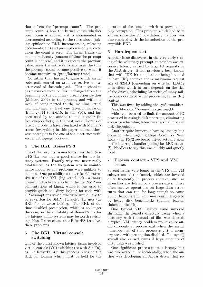
that affects the ”preempt count”. The pre-empt count is how the kernel knows whetherpreemption is allowed - it is incremented ordecremented according to the rules above (tak-ing spinlock or BKL increments it, releasingdecrements, etc) and preemption is only allowedwhen the count is zero. The kernel tracks themaximum latency (amount of time the preemptcount is nonzero) and if it exceeds the previousvalue, saves the entire call stack from the timethe preempt count became positive to when itbecame negative to /proc/latency trace).
So rather than having to guess which kernelcode path caused an xrun we receive an ex-act record of the code path. This mechanismhas persisted more or less unchanged from thebeginning of the voluntary preemption patches(Molnar, 2004) to the present, and within aweek of being ported to the mainline kernelhad identified at least one latency regression(from 2.6.14 to 2.6.15, in the VM), and hasbeen used by the author to find another (infree swap cache()) in the past week. Dozens oflatency problems have been fixed with Molnar’stracer (everything in this paper, unless other-wise noted); it is the one of the most successfulkernel debugging tools ever.
4 The BKL: ReiserFS 3
One of the very first issues found was that Reis-erFS 3.x was not a good choice for low la-tency systems. Exactly why was never reallyestablished, as the filesystem was in mainte-nance mode, so any problems were unlikely tobe fixed. One possibility is that reiser3’s exten-sive use of the BKL (big kernel lock - a coarsegrained lock which dates from the first SMP im-plementations of Linux, where it was used toprovide quick and dirty locking for code withUP assumptions which otherwise would have tobe rewritten for SMP). ReiserFS 3.x uses theBKL for all write locking. The BKL at thetime disabled preemption, which is no longerthe case, so the suitability of ReiserFS 3.x forlow latency audio systems may be worth revisit-ing. Hans Reiser claims that ReiserFS 4.x solvesthese problems.
5 The BKL: Virtual consoleswitching
One of the oldest known latency issues involvedvirtual console (VC) switching (as with Alt-Fn),as like ReiserFS 3.x this process relies on theBKL for locking which must be held for the
duration of the console switch to prevent dis-play corruption. This problem which had beenknown since the 2.4 low latency patches wasalso resolved with the introduction of the pre-emptible BKL.
6 Hardirq context
Another issue discovered in the very early test-ing of the voluntary preemption patches was ex-cessive latency caused by large IO requests bythe ATA driver. It had previously been knownthat with IDE IO completions being handledin hard IRQ context and a maximum requestsize of 32MB (depending on whether LBA48is in effect which in turn depends on the sizeof the drive), scheduling latencies of many mil-liseconds occurred when processing IO in IRQcontext.
This was fixed by adding the sysfs tunables:/sys/block/hd*/queue/max sectors kbwhich can be used to limit the amount of IO
processed in a single disk interrupt, eliminatingexcessive scheduling latencies at a small price indisk throughput.
Another quite humorous hardirq latency bugoccurred when toggling Caps, Scroll, or NumLock - the PS/2 keyboard driver actually spunin the interrupt handler polling for LED status(!). Needless to say this was quickly and quietlyfixed.
7 Process context - VFS and VMissues
Several issues were found in the VFS and VMsubsystems of the kernel, which are invokedquite frequently in process context, such aswhen files are deleted or a process exits. Theseoften involve operations on large data struc-tures that can run for long enough to causeaudio dropouts and were most easily triggeredby heavy disk benchmarks (bonnie, iozone,tiobench, dbench).
One typical VFS latency issue involvedshrinking the kernel’s directory cache when adirectory with thousands of files was deleted;a typical VM latency problem would cause au-dio dropouts at process exit when the kernelunmapped all of that processes virtual mem-ory areas with preemption disabled. The sync()syscall also caused xruns if large amounts ofdirty data was flushed.
One significant process-context latency bugwas discovered quite accidentally, when the au-thor was developing an ALSA driver that re-
LAC200622

quired running separate JACK instances forplayback and capture. A large xrun would beinduced in the running JACK process when an-other was started. The problem was identifiedas mlockall() calling into make pages present()which in turn called get user pages() causingthe entire address space to be faulted in withpreemption disabled.
Process-context latency problems were fortu-nately the easiest to solve, by the addition of areschedule with lock break within the problem-atic loop.
8 Process context - ext3fs
While ReiserFS 3.x did not get any latencyfixes as it was in maintenance mode, EXT3FSdid require several changes to achieve accept-able scheduling latencies. At least three latencyproblems in the EXT3 journalling code (a mech-anism for preserving file system integrity in theevent of power loss without lengthy file sys-tem checks at reboot) and one in the reserva-tion code (a mechanism by which the filesystemspeeds allocation by preallocating space in an-ticipation that a file will grow) were fixed by themaintainers.
9 Softirq context - the strugglecontinues
Having covered process and hardirq contexts wecome to the stickiest problem - softirqs (aka”Bottom Halves”, known as ”DPCs” in theWindows world - all the work needed to han-dle an interrupt that can be delayed from thehardirq, and run later, on another processor,with interrupts enabled, etc). Full discussion ofsoftirqs is outside the scope (see (Love, 2003))of this paper but an important feature of theLinux implementation is that while softirqs nor-mally run immediately after the hardirq that en-abled them on the same processor in interruptcontext, under load, all softirq handling can beoffloaded to a ”softirqd” thread, for scalabilityreasons.
An important side effect is that the kernelcan be trivially modified to unconditionally runsoftirqs in process context, which results in adramatic improvement in latency if the audiosystem runs at a higher priority than the softirqthread(s). This is the approach taken by the -rtkernel, and by many independent patches thatpreceded it.
The mainline Linux kernel lacks this feature,however, so minimizing scheduling latency re-
quires limiting the amount of time spent insoftirq context. Softirqs are used heavily by thenetworking system, for example looping over alist of packets delivered by the network adapter,as well as SCSI and for kernel timers (Love,2003). Fortunately the Linux networking stackprovides numerous sysctls that can be tuned tolimit the number of packets processed at once,and the block IO fixes described elsewhere forIDE also apply to SCSI, which does IO comple-tion in softirq context.
Softirqs are the main source of excessivescheduling latencies that, while rare, can stilloccur in the latest 2.6 kernel as of this writ-ing (2.6.16-rc5). Timer based route cache flush-ing can still produce latencies over 10ms, andis the most problematic remaining softirq as noworkaround seems to be available; however theproblem is known by the kernel developers anda solution has been proposed (Dumazet, 2006).
10 Performance issues
The problems described so far mostly fit thepattern of too much work being done at once insome non-preemptible context and were solvedby doing the same work in smaller units. How-ever several areas where the kernel was simplyinefficient were resolved, to the benefit of allusers.
One such problem was kallsyms lookup(), in-voked in cases like printk(), which did a lin-ear search over thousands of symbols, caus-ing excessive scheduling latency. Paulo Mar-ques solved this problem by rewriting kall-syms lookup() to use a more efficient search al-gorithm. The frequent invocation of SHATrans-form() in non-preemptible contexts to add tothe entropy pool was another latency problemsolved by rewriting the code to be more efficient.
11 Non-kernel factors
The strangest latency problem identified wasfound to have an origin completely outside thekernel. Testing revealed that moving windowson the desktop reliably caused JACK to reportexcessive delays. This is a worse situation thanan xrun as it indicates the audio device stoppedproducing/consuming data or a hardware leveltiming glitch occurred, while an xrun merelyindicates that audio was available but JACKwas not scheduled in time to process it. Theproblem disappeared when 2D acceleration wasdisabled in the X configuration which pointedclearly to the X display driver - on Linux all
LAC200623

hardware access is normally mitigated by thekernel except 2D XAA acceleration by the Xserver.
The VIA Unichrome video card used in test-ing has a command FIFO and a status register.The status register tells the X server when theFIFO is ready to accept more data. (Jones andRegehr, 1999) describes certain Windows videodrivers which improve benchmark scores by ne-glecting to check the status register before writ-ing to the FIFO; the effect is to stall the CPU ifthe FIFO was full. The symptoms experiencedwere identical to (Jones and Regehr, 1999) - themachine stalled when the user dragged a win-dow. Communication with the maintainer ofthe VIA unichrome driver (which had been sup-plied by the vendor) confirmed that the driverwas in fact failing to check the status registerand was easily fixed.
12 The -rt kernel and the future
The above solutions all have in common thatthey reduce scheduling latencies by minimiz-ing the time the kernel spends with a spin-lock held, with preemption manually disabled,and in hard and soft IRQ contexts, but do notchange the kernels behavior regarding whichcontexts are preemptible. Modulo a few re-maining, known bugs, this approach is capableof reducing the worst case scheduling latenciesto the 1-2ms range, which is adequate for au-dio applications. Reducing latencies further re-quired deep changes to the kernel and the rulesabout when preemption is allowed. The -rt ker-nel eliminates the spinlock problem by turningthem into mutexes, the softirq by the softirqmethod previously described, and the hardirqissue by creating a set of kernel threads, one perinterrupt line, and running all interrupt han-dlers in these threads. These changes result ina worst case scheduling latency close to 50 mi-croseconds which approaches hardware limits.
13 Conclusions
One of the significant implications of the storyof low latency in kernel 2.6 is that I believe itvindicates the controversial ”new kernel devel-opment process” (Corbet, 2004) - it is hard toimagine Linux 2.6 evolving into a world class au-dio platform as rapidly and successfully as it didunder a development model that valued stabil-ity over progress. Another lesson is that in op-erating systems as in life, history repeats itself.Much of the work done on Linux 2.6 to support
soft realtime applications, like IRQ threading,was pioneered by Solaris engineers in the early1990s (Vahalia, 1996).
14 Acknowledgements
My thanks go to Ingo Molnar, Paul Davis, An-drew Morton, Linus Torvalds, Florian Schmidt,and everyone who helped to evolve Linux 2.6into a world class realtime audio platform.
References
Jonathan Corbet. 2004. Another lookat the new development model.https://lwn.net/Articles/95312/.
Eric Dumazet. 2006. Re: Rcu la-tency regression in 2.6.16-rc1.http://lkml.org/lkml/2006/1/28/111.
Michael B. Jones and John Regehr. 1999. Theproblems you’re having may not be the prob-lems you think you’re having: Results from alatency study of windows nt. In Proceedingsof the 7th Workshop on Hot Topics in Oper-ating Systems (HotOS VII), pages 96–101.
Robert Love. 2003. Linux Kernel Development.Sams Publishing, Indianapolis, Indiana.
Ingo Molnar. 2004. [announce] [patch]voluntary kernel preemption patch.http://lkml.org/lkml/2004/7/9/138.
Uresh Vahalia. 1996. Unix Internals: The NewFrontiers. Prentice Hall, Upper Saddle River,New Jersey.
LAC200624

A Low-Latency Full-Duplex Audio over IP Streamer
Asbjørn SÆBØ and U. Peter SVENSSONCentre for Quantifiable Quality of Service in Communication Systems
NTNU – Norwegian University of Science and TechnologyO.S. Bragstads plass 2E
N-7491 TrondheimNorway
[email protected], [email protected]
Abstract
LDAS (Low Delay Audio Streamer) is software fortransmitting full duplex high-quality multi-channelaudio with low end-to-end latency over IP networks.It has been designed and implemented as a tool forresearch into distributed multimedia interaction andquality of service in telecommunications. LDAS runson Linux, using the ALSA sound drivers and li-braries. It uses UDP as its transport protocol. Aflow control scheme is used to keep the sender andreceiver synchronised and to deal with transmissionerrors. Tests have shown end-to-end latencies (fromanalog input to analog output) down to around fivemilliseconds over a minimal network.
Keywords
audio, streaming, latency, IP network
1 Introduction
The field of telecommunications is changing,with new technologies making new services pos-sible. One aspect of this is the increasing useof various kinds of transmission of audio andmultimedia over packet-switched networks us-ing the Internet Protocol (IP).
Related to this, ”Quality of Service” (QoS)is a topic of current interest in telecommuni-cations. Traditionally, this deals with technicalspecifications and guarantees. A wider interpre-tation may also take into account the quality ofservice as experienced by the user. In this re-spect, an increased quality of service may notonly be an increase in the quality of a givenservice (like voice communication), but to im-prove the user experience by offering a serviceof inherently higher quality, something that isnot only better, but more. (An example mightbe to replace a one-channel voice communica-tion service with a voice communication servicewith 3D-audio.)
There is an untapped potential for servicesutilising audio and multimedia over IP thatwould give a better quality of service, as expe-rienced by the user. The ultimate telecommu-
nications system would enable one to achievevirtual presence and true interaction betweenthe endpoints of the communication. Currentcommon systems, like internet telephony (Voiceover IP, VoIP) and video conferencing do notfully achieve this. A primary aspect of this topicis how such services should work, on a technicallevel. Further, and perhaps even more interest-ing, is how they may be used, and how the userwill experience them.
Our aim is therefore to explore and investi-gate more advanced and demanding communi-cation services, focusing on the audio side ofdistributed multimedia interaction. The generalsituation would be one where two acoustical sit-uations are connected through the network insuch a way as to achieve transmission of thecomplete acoustic environments. Examples ofsuch applications, and our immediate targets,are ensemble playing and music performanceover the network, and transmission of variouskinds of 3D audio (binaural, Ambisonics, mul-tichannel). This has been demonstrated in anumber of studies, e.g. (Woszczyk et al., 2005).
Latency is the most interesting and demand-ing of the factors limiting these kinds of services.Available data storage capacity, data transmis-sion capacity (bandwidth) and processing ca-pacity are all steadily increasing, with no hardbounds in sight. Transmission time, however, isfundamentally limited by the the speed of light.And, as will be further discussed below, low la-tency is in many cases important and necessaryin order to achieve interaction. In addition tohigh quality overall, low latency should there-fore be emphasised.
For our exploration, a tool suitable for suchservices was needed. This tool should be capa-ble of transmission of high quality, low latencyaudio. It should also be open, to facilitate con-trol over all aspects and parameters of the trans-mission process. Several such applications ex-ist, from the simple ones to the very advanced
LAC200625

ones. For many of these, source code is notaccessible, making studies of their internals orchanging of their workings next to impossible.Others do, in various ways, not meet our needs,although StreamBD, used at CCRMA, (Chafeet al., 2000), might have had adequate prop-erties. The development of such a tool wouldgive valuable insights into the specific problemsassociated with these topics, give full controlof all aspects of the tool and its usage and bea good way to start the explorations. So, thetask of developing LDAS - the Low Delay Au-dio Streamer, was undertaken, using previouswork done at NTNU (Strand, 2002) as a start-ing point.
2 Requirements and specifications
The two immediate target applications are net-worked ensemble playing and transmission ofacoustical environments. The first involves mu-sicians at different locations, connected by anetwork, performing music together. The sec-ond involves the transmission of enough infor-mation from one site to another to be able torecreate the acoustic environment of the firstsite at the second site in a satisfactorily manner.The main requirements of these applications arediscussed below.
2.1 Audio qualityAudio quality should be high. For simplicity,the lower limit for quality has been set equalto that of an audio Compact Disc. This meansa sampling frequency of 44.1kHz (or 48kHz) orhigher, and a sample depth (word length) of atleast 16 bits for uncompressed PCM.
The number of channels available should beat least two (which will allow for transmission ofstereo or binaural signals), but preferably eightor more (which will allow for various kinds ofmulti-channel and three-dimensional audio for-mats like Ambisonics).
2.2 Latency considerationsLatency is important for interaction. In partic-ular, it is known that excessive inter-musicianlatency is detrimental to ensemble playing, oneof our target applications (Bargar et al., 1998).The fundamental latency requirement is there-fore that the latency should be so low that it willnot hinder successful ensemble playing acrossthe established connection.
Some investigations into what constitutes tol-erable delay has been done, but few definite con-clusions have been given. Experiments, using
hand-clapping as the musical signal, have foundan “optimal” delay (with respect to tempo sta-bility) of 11.6 milliseconds (Chafe and Gurevich,2004). Based upon these data and their own ex-periences, (Woszczyk et al., 2005) suggest thatlatencies of 20ms to 40ms are “easily tolerated”,and that even higher latencies may be accept-able after training and practice.
Experiments conducted at the acousticsgroup at NTNU have concluded that latencieslower than 20 milliseconds do not seem to influ-ence the ensemble playing much, while latenciesabove 20 milliseconds may may lead to a less“tight” rhythm, with the two musicians not fol-lowing each other as well (Winge, 2003). On theother hand, (Lago and Kon, 2004) claims thatlatencies up to at least 30 milliseconds shouldbe considered normal and in most situations ac-ceptable, and that latencies of this order willnot impair musical performance. Further, in-formal evidence, based upon the experience ofa number of practising musicians, indicates thatlatencies of 30 ms and maybe up to 50ms maybe tolerable.
For comparison: Sound in air at room tem-perature travels at approximately 345 metersper second. This gives a latency of about threemilliseconds per meter. Two musicians two me-ters apart will experience a delay of six millisec-onds. The width of a typical sympony orchestraon stage may be around 15 to 20 meters, cor-responding to a latency between the outermostmusicians on the order of 50 milliseconds. (Itshould be noted that an orchestra also has ex-ternal synchronisation in the form of a conduc-tor.)
Obviously, for networked ensemble playing,network transmission time may make up a largepart of the total latency. (With factors like A/Dand D/A conversion, buffering in the soundcard, data processing and handling by applica-tion and OS and travel time for sound waves inair making up for the rest.) Whether a suffi-ciently low latency is possible is therefore to alarge degree dependent upon the “network dis-tance” between the participants.
Based upon the indications above, the oper-ating requirement was set to have an end toend latency (analog signal to analog signal) ofless than 20 milliseconds for transmission overa campus-wide LAN. To avoid unnecessary la-tency, it was decided that uncompressed audioshould be transferred. While expending effortinto keeping the latency low, it should be re-
LAC200626

membered that latency requirements must bebalanced against the robustness of transmission.This compromise should be tunable.
2.3 Network protocol
Using IP (Internet Protocol) as the networklayer protocol is a given, since the area for whichLDAS is intended is audio over IP.
The two main transport protocols used overIP are TCP (Transmission Control Protocol)and UDP (User Datagram Protocol). TCP pro-vides a reliable, connection-oriented transmis-sion mechanism. Lost packets are retransmit-ted, and flow and congestion control is part ofthe protocol. UDP is a connectionless protocolwith very limited delivery guarantees. Packetssent via UDP may not arrive at the destinationat all, they may arrive out of order, or they mayarrive as duplicates. The only guarantee givenis that if a packet does arrive, its contents are in-tact. UDP supports broadcasting and multicas-ting (which TCP does not), but does not havebuilt in flow and congestion control. (Stevenset al., 2004).
For networked ensemble playing, the reliabil-ity of TCP is not called for. A low latency isdeemed more important than totally reliable de-livery of all data. Some data loss may be accept-able, and retransmission of lost packets may bea waste of time and capacity, as they may wellbe discarded due to arriving too late when theyfinally arrive. Neither will TCP’s flow and con-gestion control be the optimal way to rate-limitLDAS traffic. Methods taking into account thenature of the service, built into the applicationitself, will be preferable. (Until flow control isimplemented in LDAS, LDAS traffic will not beTCP-friendly. But, at least for the research pur-poses and situations, this is acceptable.)
As multi-way communication is envisioned, itis possible, maybe also probable, that LDASmay be extended to multicast, for which UDP isneeded. As the distinguishing features of TCPare not necessary for LDAS, not choosing TCPas the transport protocol is not a disadvantage.On the other hand, the multicast feature ofUDP may be essential. On the basis of this,UDP was chosen as the transport protocol.
It is necessary for LDAS that the order ofpackets be maintained and the relative place-ment of packets in time be correct. This fea-ture is not delivered by UDP. LDAS shouldtherefore implement its own protocol, on topof UDP, to provide the necessary features for
packet stream tracking and control.Alternative protocols are DCCP (Data-
gram Congestion Control Protocol, http://www.icir.org/kohler/dcp/) and RTP (RealTime Protocol, http://www.faqs.org/rfcs/rfc3550.html). DCCP is intended as a sub-stitute for UDP for applications like these, butis still a work in progress. RTP sits on top ofUDP, and is a transport protocol for real timeapplications. It was, however, found to be morecomplex than needed for this case.
2.4 SynchronisationIt is mandatory that the sending and the re-ceiving parts be kept synchronised, keeping thelatency as low and as constant as circumstanceswill allow. To minimise the effects of net-work transmission time jitter, the receiving partshould maintain a buffer of received audio data.The amount of data to be held in this buffershould be setable, so it can be balanced againstthe latency requirements.
3 Implementation
The high-level system architecture is currentlya ”pairwise peer-to-peer” system, i.e. two equalprograms sending and receiving data to andfrom each other.
The structure of the application is shown infigure 1. There are three threads running in par-allel, a recorder/sender, a receiver and a play-back task. The recorder/sender thread is run-ning independently of the two other threads,while the receiver and the playback threads arelinked through a common data structure, thereceiver queue. All three threads are runningscheduled as SCHED FIFO tasks.
3.1 The data stream and the packetformat
Audio is a continuous signal, which is digitisedby the audio interface into a stream of samples.It is, however, practical to handle chunks of thestream as units when processing and transmit-ting the data. The audio stream is thereforedivided into a series of application level pack-ets.
This packet stream is the connection betweenthe sender and the receiver. The packet formatis quite simple. Each packet consists of one pe-riod1 of audio data, as delivered from the au-dio interface. (Currently, the ALSA interleavedformat is used.) To these data is appended a
1In the ALSA sense.
LAC200627

Read audio datafrom sound card
Build packet,send to network
Process audio
Receive packetfrom network
Enqueue packet
from enqueued dataBuild audio period
Write audio datato sound card
Process audio
N+1 NN+2N+3
Figure 1: Application architecture and conceptual flowchart. Blue (straight, vertical) lines showthe flow of the audio data, red (curved) lines show program flow. From left to right, there is therecorder/sender thread, the receiver thread and the playback thread. Audio is acquired and playedback via the audio interfaces, at the bottom of the figure, and sent to, and received from, thenetwork at the top of the figure. The square boxes at the bottom of the figure are, from left toright, the input sound card buffer, the receiver queue and the output sound card buffer. The dashedboxes indicates the possibility for additional processing, currently not present, of the audio data.
sequence number and a time stamp, as shownin figure 2.
Positions in the audio stream are identifiedby the sequence number of the packet and aframe-level offset into the packet. Of particularinterest is the playback position kept by the re-ceiver. This is the position of the data that is“next in turn” to be sent to the playback soundcard.
3.2 The receiver queueThe receiver queue is the central data structureof the program. In this queue, received pack-ets are temporarily stored until their audio datahave been played back. (No copying of datatakes place during enqueuing. The queue is im-plemented as an array of pointers to packets, ad-dressed modulo the length of the array to givea circular buffer.) The queue, containing thepacket corresponding to the playback positionand any more recent packets, acts as a slidingwindow onto the incoming packet stream.
A primary purpose of the queue is to bufferthe incoming packet stream, absorbing the ef-fects of network transmission time jitter. Thesetting of the nominal length of the queue, i.e.the number of audio periods we try to keep inthe queue, allows for the trading of latency forrobustness. More data in the queue will givea higher latency, but also more leeway for the
occasional late arriving packet to still come intime.
The queue, together with the packet format,implicitly defines a simple protocol that makesthe application capable of handling the short-comings of UDP. Packets are inserted into thequeue in correct order, according to their se-quence numbers. Lost (or missing) packets aredetected, and dummy data (currently silence)substituted in their place. Duplicate packets,and packets arriving too late, are detected andrejected. Altogether, this gives a data streamthat is ordered and without gaps.
The queue is further central in the synchro-nisation of sender and receiver, as discussed be-low.
3.3 Synchronisation and driftadjustment
There are two kinds of synchronisation issues,synchronisation on a large scale and drift ad-justment. Both are handled in the receiverqueue.
The first, synchronisation, is handled by thereceiver thread. As mentioned above, the re-ceiver queue is a sliding window onto the packetstream. The purpose of the synchronisation isto position this window correctly. This is doneby monitoring the sequence numbers of the in-coming packets. A packet is said to be “early” if
LAC200628

Audio data (one period) Seq. Num. Time stamp
Frame 1 Frame 2 Frame M
Ch. 1 sample Ch. 2 sample Ch. N sample
Figure 2: LDAS packet format, the payload of the UDP packet.
its sequence number is so high that it would falloutside of the queue. If an early packet arrives,this is a sign that the receiver is lagging, and thequeue is resynchronised. Resynchronisation re-sets the queue, setting a new playback position,so that the length of the queue, as measuredfrom the playback position to the end of thequeue (including the early packet) equals thenominal queue length.
Similarly, “late” packets are packets arrivingafter they should have been played back, i.e.with a sequence number lower than the sequencenumber corresponding to the current playbackposition. From the number of recent late arriv-ing packets, a “lateness factor” is computed. Ifthis value gets too high, the receiver is assumedto be leading, and the receiver queue is resyn-chronised.
Although nominally equal, the sampling fre-quencies of the sound cards at the sending andreceiving ends will in practice differ slightly.Over time, this difference will lead to more sam-ples being produced than consumed, or viceversa, and this aggregation or starvation of datawill cause the sender and the receiver to driftapart. To compensate for this, more smoothlythan would be done by large scale synchronisa-tion alone, the playback thread does drift ad-justment. From the nominal queue length, anupper and a lower limit is computed. If thelow pass filtered actual queue length increasesor decreases beyond those limits, single samplesare skipped or reused to adjust the rate of dataconsumption as appropriate to counteract thedrift. There is at most one sample of adjust-ment per period, giving a range of adjustmentthat is inversely proportional to the period size.
A consequence of this adjustment is that the
audio periods sent to the sound card will ingeneral not correspond to those of the receivedpackets, but be built from audio data from morethan one packet.
4 Similar solutions
For comparison purposes, this section gives abrief overview of other available open sourcesoftware similar to LDAS. The information isgleaned from available documentation and vari-ous other sources. Except for llcon, the authorsof this paper have not done actual experimentswith these other solutions.
Netjack (Hohn et al., 2006) is a mechanismfor transporting realtime audio over an IP Net-work using UDP. It is fully integrated with Jack.Full duplex transmission of uncompressed stereodata between two computers is offered. Netjackslaves one jackd to the other, and synchronisesthe slave jack using the incoming packet data.Which technique is used for the synchronisationis not clear from the available documentation.
An earlier solution is jack.udp (Drape, 2005).This is an udp packet transport that sends jackaudio data, using UDP, over local networks be-tween two jack enabled computers. For correctoperation, jack.udp needs some form of externalsynchronisation between the soundcards of thecomputers.
The StreamBD software (SoundWIREGroup, CCRMA, Stanford, 2002) may, amongother things, be used for transmission of audioover a network. It uses ALSA or OSS audiodrivers, and provides multiples channels ofuncompressed audio. TCP is used for oneway transmission, UDP or non-guaranteedvariants of TCP for bidirectional transmission.Whether, or how, synchronisation is achieved is
LAC200629

not described in the available documentation.The llcon (Fischer, 2006) software differs from
the rest in that it is aimed at situations withlimited bandwidth, like 256kbps DSL lines. Itmay also connect more than two endpoints.Endpoint clients connect to a central server,which mixes all incoming signals and returns themix to the clients. At the clients, stereo is in-put and mixed to one channel before sending thedata to the server. The sampling frequency is 24kHz, and IMA-ADPCM coding, which gives acoding delay of one sample, is used to compressthe audio data rate to 96 kbps.
5 Latency measurements
For initial testing and latency measurements ofLDAS, two PCs were used. PC-1 was equippedwith an Intel P4 CPU, PC-2 had an Intel P3CPU at 1Ghz. The computers had 512 MB ofRAM each, and were equipped with M-AudioDelta44 audio interfaces. Both computers wererunning Linux set up for real time operation,with 2.6.12 multimedia kernels and associatedsetup from DeMuDi 1.2.0. (PC-2 was a regu-lar DeMuDi installation, while PC-1 was “side-graded” from Debian Sarge.)
The computers were connected via a switchof the regular campus LAN. The network roundtrip time, as reported by “ping” was 0.1 ms. Forthe measurements, LDAS was version 0.1.1 plusa small fix for a hard coded period size. Audiotransmission was two-channel full duplex, usingthe ldas mate executable. PC-2 was controlledvia SSH logins from PC-1, with the correspond-ing network traffic between the two computersfollowing the same network route as the LDAStransmissions.
Latency measurements were done on onechannel, one way, using an impulse responsemeasurement system, a computer running theWinMLS (Morset, 2004) measurement software.Responses were measured from the analog in-put of PC-1’s sound card to the analog outputof PC-2’s sound card. Several combinations ofperiod size and nominal receiver queue lengthwere tried. For each combination, six impulseresponse measurements were taken. From theimpulse responses, the total latency through thetransmission chain was computed. The resultsare given in table 1.
While measuring, audio from a CD player wastransmitted on the remaining channel from PC-1 to PC-2, and also on both channels in theopposite direction. The quality of the transmis-
Period Queue Mean Standardsize length latency deviation
A 128 3 15.2 0.8B 128 1 11.0 0.8C 128 0.1 8.2 0.6D 64 1 5.8 0.4E 64 0.1 4.9 0.4F 32 0.1 3.1 0.2G 16 1 2.6 0.1
Table 1: Total latency for audio transmissionwith LDAS. The latency is measured from ana-log input to analog output for various combi-nations (marked A to G) of audio period sizeand nominal receiver queue length. The latencymean value and standard deviation are given inmilliseconds. Period size is measured in frames(samples), and the nominal length of the re-ceiver queue in periods. Sampling frequency is48kHz.
sion was subjectively evaluated by monitoringthe received audio signals (mostly one directionat a time) for audible drop-outs and other formsof distortion or quality reduction. For the trans-mission from PC-1 to PC-2, combinations A, Band D were robust, with no artifacts noted. Forcombinations C and E, a few distortions (overthe course of a few minutes) were noted. Thedistortions had the character of brief crackles.Transmission from PC-2 to PC-1 seemed some-what less robust. Infrequent distortions werenoted for combination D, and more frequent dis-tortions for E, F and G. Especially for the lowerlatency setups, transmission from PC-2 to PC-1was susceptible to other use of PC-1, with e.g.a “find /usr” with output to a terminal win-dow leading to quite a bit of “stuttering” in thetransmitted audio.
6 Conclusions
A software tool for transmission of high-qualitymultichannel audio over IP networks has beendesigned and implemented. As one target appli-cation of the tool is networked ensemble play-ing, emphasis has been placed on achieving lowlatency. Testing has shown that the tool is capa-ble of achieving robust full duplex transmissionwhile keeping latencies below our stated goalof 20 milliseconds on a local area network. Ifsmall transmission artifacts are accepted, evenlower latencies may be obtained. While not fin-ished, the software is in a state where it may be
LAC200630

used for experimental work and research intouser experienced quality of service in telecom-munications.
7 Acknowledgements
Richard Lee Revell, of Mindpipe Audio, haswritten parts of LDAS, in cooperation withAsbjørn Sæbø. We are grateful for his assis-tance. The authors also thank Svein Sørsdaland Georg Ottesen of SINTEF, Jon Kare Hel-lan of UNINETT and Paul Calamia, currentlyat Rensselaer Polytechnic Institute, for valuablediscussions and advice.
8 Availability
The LDAS software has been released underthe GNU General Public License. It maybe downloaded from http://www.q2s.ntnu.no/~asbjs/ldas/ldas.html.
References
Robin Bargar, Steve Church, Akira Fukuda,James Grunke, Douglas Keislar, Bob Moses,Ben Novak, Bruce Pennycook, Zack Zettel,John Strawn, Phil Wiser, and WieslawWoszczyk. 1998. Technology report TC-NAS98/1networking audio and musing using in-ternet2 and next-generation internet capabili-ties. Technical report, Technical Council, Au-dio Engineering Society, Inc.
Chris Chafe and Michael Gurevich. 2004. Net-work time delay and ensemble accuracy: Ef-fects of latency, assymetry. In 117th AudioEng. Soc. Convention Preprints. Audio Eng.Soc., October. Preprint 6208.
Chris Chafe, Scott Wilson, Randal Leistikow,Dave Chisholm, and Gary Scavone. 2000. Asimplified approach to high quality music andsound over IP. In COST-G6 Conference onDigital Audio Effects (DAFx-00), December7 – 9.
Rohan Drape. 2005. jack.udp. http://www.slavepianos.org/rd/sw/sw-23.
Volker Fischer. 2006. Low latency (internet)connection. http://llcon.sourceforge.net/.
Torben Hohn, Dan Mills, and Robert Jons-son. 2006. Netjack v. 0.7. http://netjack.sourceforge.net/.
Nelson Posse Lago and Fabio Kon. 2004. Thequest for low latency. In International Com-puter Music Conference, Miami, November.
Lars Henrik Morset. 2004. WinMLS 2004.http://www.winmls.com.
SoundWIRE Group, CCRMA, Stan-ford. 2002. StreamBD 1.0b. http://ccrma.stanford.edu/groups/soundwire/software/newstream/docs/.
W. Richard Stevens, Bill Fenner, and An-drew M. Rudoff. 2004. UNIX Network Pro-gramming, volume 1. Addison-Wesley, thirdedition.
Ola Strand. 2002. Distribuert multimediasamhandling. Master’s thesis, NorwegianUniversity of Science and Technology, NTNU,Dept. of Telecomm., Acoustics Group. (Innorwegian).
Hakon Liestøl Winge. 2003. Musikksamspillover IP. Term project, NTNU, Norwe-gian University of Science and Technology,September. (In norwegian).
Wieslaw Woszczyk, Jeremy R. Cooperstock,John Roston, and William Martens. 2005.Shake, rattle and roll: Getting immersed inmultisensory interactive music via broadbandnetworks. J. Audio Eng. Soc., 53(4):336 –344, April.
LAC200631

LAC200632

swonder3Dq : Auralisation of 3D objects with Wave FieldSynthesis
Marije BAALMANInstitute for Communication Sciences, Technische Universitat Berlin
Einsteinufer 17Berlin, Germany
Abstract
swonder3Dq is a software tool to auralise three di-mensional objects with Wave Field Synthesis. Itpresents a new approach to model the radiation char-acteristics of sounding objects.
Keywords
Wave field synthesis, spatialisation, radiation char-acteristic, physical modelling
1 Introduction
Wave Field Synthesis (WFS) is an interestingmethod for spatialisation of electronic music.Its main advantage is that it has no sweet spot,but instead a large listening area, making thetechnology attractive for concert situations.
Yet, whenever acoustic instruments are com-bined with electroacoustic sounds in concerts,a common problem is that the electroacousticpart tends to lack depth and extension in com-parison with the sound from the acoustic in-struments. Misdariis (1) and Warusfel (2) haveproposed special 3D loudspeaker arrays to simu-late different radiation characteristics. A prob-lem with this technique is that the object itselfis static; a movement of the source can only becreated by physically moving the loudspeakerarray.
In current Wave Field Synthesis applicationsthere are only solutions for monopole pointsources and plane waves. There are some re-ports of ad hoc solutions to simulate largersources, such as the Virtual Panning Spots (3)and the auralisation of a grand piano (4) byusing a few point sources. Currently, work isdone on implementing radiation characteristicsfor point sources (5). By definition radiationcharacteristics are only applicable at a certaindistance from the object modelled. Since WFSsources can get very close, it makes sense to lookfor a general solution for auralising arbitrarilyshaped sources.
2 Theory
2.1 Source model
The wave field of a sounding object can be ap-proximated by superposition of the wave fieldsof a number of point sources. The locations ofthese point sources and the number can be cho-sen arbitrarily, but it make sense to choose thelocations on the surface of the object. This sep-arates the calculation of the vibration of the ob-ject itself (which can be done with various meth-ods, such as finite element methods or modalsynthesis) from the calculation of the radiationof the sound from the object into the air.
For a correct calculation of the radiated soundfield, the vibration of the surface must be spa-tially sampled. Here there is the danger of un-dersampling (6); this danger is twofold: first,spatial amplitude variations of the surface vi-bration may be lost, and secondly, dependingon the frequency content of the sound, spatialaliasing may occur in a similar way as for theWFS speaker array itself.
In practice the sound emitted from differentpoints on the object’s surface will be correlated.For a practical implementation it is useful toassume that for a point Ψ on the surface:
SΨ(~rΨ, φ, θ, ω) = S(ω)G(~rΨ, φ, θ, ω) (1)
i.e. from each point source that is part of thedistribution a source signal S(ω) filtered withG is emitted (G depending on the location ~rΨ
of the point source Ψ, the angular frequencyω of the sound and the direction angles φ andθ). Applied to the reproduction of electronicmusic, this will allow a composer to determinethe filter characteristics of his source object andthe sound signal emitted by the source indepen-dently. Thus, the resulting filtering function foreach speaker can be determined in advance andthe signal input can be convolved in realtimewith this filter.
LAC200633

x
z
y
bR
l
m
S
bΨ~r0
b
y0 ~∆r0
b
b
~∆r0
Figure 1: The stationary point (xm, y0, 0) lieson the cross-section of the line m (in plane S)and the plane through Ψ and the reference linel.
2.2 Adaptation of the WFS-operator
For WFS reproduction of a 3-dimensionalsource object the commonly used 21
2D-operator
(7) is not sufficient as its derivation only sourcesin the same plane as the array and reference lineare taken into account. In (8) the WFS operatorfor points outside of the horizontal plane was de-rived, starting from the Rayleigh integrals. Themain difference from the 21
2D-operator is the
calculation of the stationary point:
y0 = yR + (yΨ − yR)zR
zΨ + zR
(2)
where zR is the z-coordinate of the receiverand zΨ of the source point (see also figure 1).The driver function of a speaker for the contri-bution of one monopole source point becomes:
Q(x, ω) =
S(ω)
√
jk
2π
√
∆r0
∆r0 + r0
cos(φ0)e−jkr0
√r0
(3)
the speaker being assumed to be on the x-axis.
It should be noted that the actual elevationwill not be heard, when the elevated source isplayed back by the WFS-array. The elevatedpoints are mainly of interest, because their con-tributions will interfere with those of the pointsin the horizontal plane.
Figure 2: Snapshot of the graphical user inter-face of swonder3Dq
3 Implementation
The software enables to calculate the filters forWFS reproduction for several sound objects.The objects themselves are defined by their geo-metrical data and the radiation filters at severalpoints on the surface. Objects can be positionedand given different orientations in space. Figure2 is a snapshot of the graphical user interface.There is an OpenGL viewer included to look atthe object. The user can choose between defin-ing filters of each node, or choose a multichan-nel audiofile which has the sound for each node(e.g. calculated with Modalys (9)). The pro-gram then calculates the WFS operators or theloudspeaker signals and saves them to disk.
A second part of the software enables the userto load a project and listen to the desired objecton the desired location with the desired orienta-tion. This part of the software can be controlledwith OSC. BruteFIR (10) is used as the convo-
LAC200634
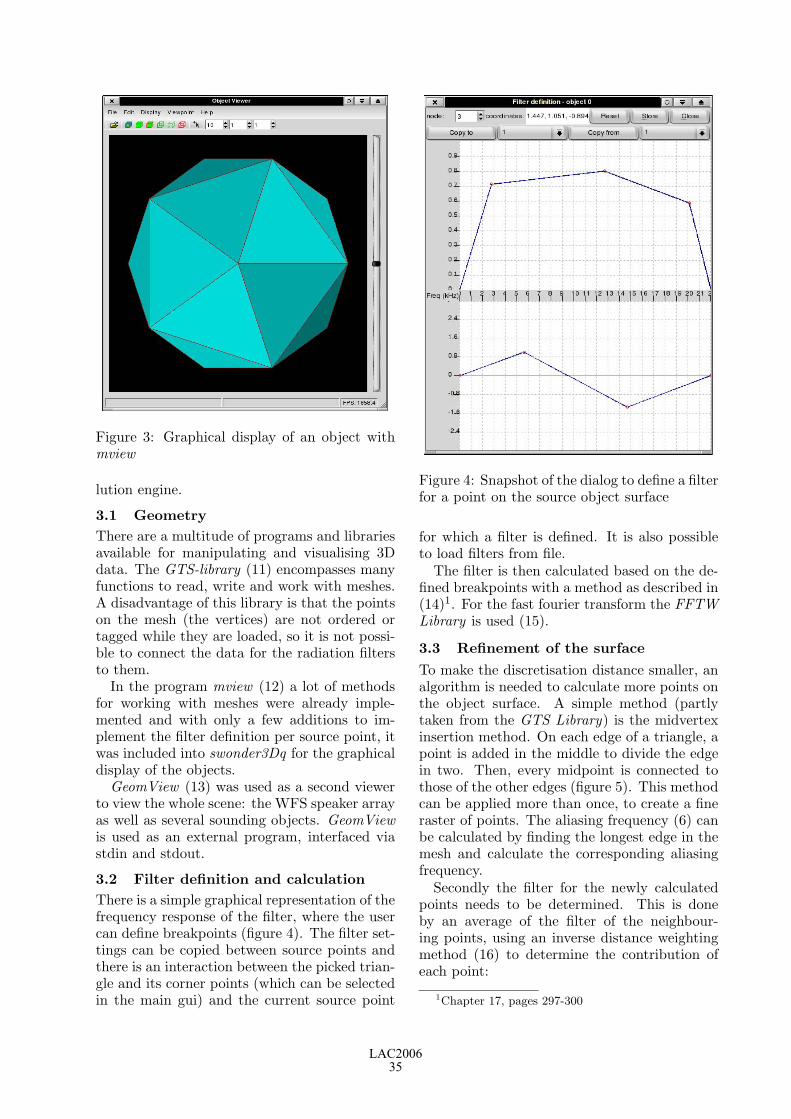
Figure 3: Graphical display of an object withmview
lution engine.
3.1 Geometry
There are a multitude of programs and librariesavailable for manipulating and visualising 3Ddata. The GTS-library (11) encompasses manyfunctions to read, write and work with meshes.A disadvantage of this library is that the pointson the mesh (the vertices) are not ordered ortagged while they are loaded, so it is not possi-ble to connect the data for the radiation filtersto them.
In the program mview (12) a lot of methodsfor working with meshes were already imple-mented and with only a few additions to im-plement the filter definition per source point, itwas included into swonder3Dq for the graphicaldisplay of the objects.
GeomView (13) was used as a second viewerto view the whole scene: the WFS speaker arrayas well as several sounding objects. GeomViewis used as an external program, interfaced viastdin and stdout.
3.2 Filter definition and calculation
There is a simple graphical representation of thefrequency response of the filter, where the usercan define breakpoints (figure 4). The filter set-tings can be copied between source points andthere is an interaction between the picked trian-gle and its corner points (which can be selectedin the main gui) and the current source point
Figure 4: Snapshot of the dialog to define a filterfor a point on the source object surface
for which a filter is defined. It is also possibleto load filters from file.
The filter is then calculated based on the de-fined breakpoints with a method as described in(14)1. For the fast fourier transform the FFTWLibrary is used (15).
3.3 Refinement of the surface
To make the discretisation distance smaller, analgorithm is needed to calculate more points onthe object surface. A simple method (partlytaken from the GTS Library) is the midvertexinsertion method. On each edge of a triangle, apoint is added in the middle to divide the edgein two. Then, every midpoint is connected tothose of the other edges (figure 5). This methodcan be applied more than once, to create a fineraster of points. The aliasing frequency (6) canbe calculated by finding the longest edge in themesh and calculate the corresponding aliasingfrequency.
Secondly the filter for the newly calculatedpoints needs to be determined. This is doneby an average of the filter of the neighbour-ing points, using an inverse distance weightingmethod (16) to determine the contribution ofeach point:
1Chapter 17, pages 297-300
LAC200635

b b
b
Figure 5: Refinement of a triangle with the mid-vertex insertion method
b
b × b
b
b
b b
b
+
b
b b
b
=
b
b
b
b
b
Figure 6: Averaging of the filter values. Onthe left is shown from which point the averageis taken: × is the new point, • are the neigh-bourpoints. On the left is shown how the break-points are added when averaging.
Zj =
∑ni=1
Zi
hβij
∑ni=1
1
hβij
(4)
Zj is the value of the new point j, Zi of theneighbour point i, hij the distance from point i
to j, and β a factor that defines the weightingof the distance, usually set to β = 2. In thiscase the factor β can be interpreted as a kindof measure how well the sound is propagatedthrough the material of the object.
The averaging between two filters is calcu-lated as follows (see also figure 6): for eachbreakpoint from either filter the correspondingvalue on that frequency value is calculated forthe other filter. The new filter then has a break-point value at that frequency value, which is anaverage of the two breakpoints of the two fil-ters. The average is taken from the real andimaginary parts of the coefficients.
3.4 3D WFS Calculation
Steps in the calculation of the WFS filters (foreach object, at each location specified):
1. Per source point:
• Check: is the source point audible (vis-ible) for the loudspeaker?
• Calculation of delay and volume factoraccording to the WFS operator
• Convolution of the WFS-delay andvolume with the filter for that sourcepoint
2. Addition of all filters of the source for eachloudspeaker
3. Save filter to disk
As the software is still in an experimentalstate, there is a choice between defining thesource points as monopoles or as dipoles. Inthe case of a dipole, the main axis of radiationis in the direction of the normal (pointing out-wards) on the surface; in the case of points onthe corners of triangles which are not on thesame plane, this normal is an average of thenormals of the triangles it is a corner point of.
When a source point is at the back side ofthe object, a direct path of the sound to theloudspeaker is not possible and this source pointshould not be taken into account. Diffraction ofsound waves around the object is neglected inthis case.
4 First tests
Preliminary listening tests on a frontal WFS-speaker array of 24 loudspeakers (at 12.5cmdistance) show that this approach does give astronger spatial impression of a sound source.
However, it became apparent that the neglec-tion of diffraction cannot be allowed. As fordifferent speakers, different points of the objectwill be at the backside (figure 7), sound willarrive from speakers to parts of the listeningarea that should be obscured when neglectingdiffraction. Thus some sense of diffraction iscreated, but at a much later stage than should
b
b
b
b
b
b
b
b
b source
P
sound arrives here
Figure 7: Illustration of the audibility problem.The point P is only audible for the gray speakerson the right, yet the sound from these speakerswill arrive on the left side of the listening area.
LAC200636

be. We will need to find a different approach inorder to take the diffraction of the sound aroundthe object into account properly.
5 Conclusions and future work
An extension of the WONDER software (17)was presented which enables the calculation ofWFS auralisation for complex sound sources.While its first aim is to be used for WFS au-ralisation, several concepts introduced could beused in other 3D audio applications, such as bin-aural representation.
Further research will be done on how to takethe diffraction of waves around objects into ac-count, before implementing that feature. Fu-ture work will include listening experiments, aswell as doing usability tests by working withcomposers using the software.
6 Acknowledgements
The work on swonder3Dq is part of a Ph.D. re-search project funded by the NaFoG in Berlin,Germany.
7 References
[1] N. Misdariis, O. Warusfel & R. Causse. Ra-diation control on a multi-loudspeaker de-vice. In ISMA 2001, 2001.
[2] N. Misdariis & T. Caulkins O. Warusfel,E. Corteel. Reproduction of sound sourcedirectivity for future audio applications. InICA 2004, 2004.
[3] G. Theile, H. Wittek & M. Reisinger.Wellenfeld-synthese verfahren: Ein wegfur neue moglichkeiten der raumlichentongestaltung. In 22nd Tonmeisterta-gung, Hannover, Germany, 2002 Novem-ber, 2002.
[4] I. Bork, & M. Kern. Simulation der schal-labstrahlung eines flugels. In DAGA ’03,2003.
[5] O. Warusfel & N. Misdariis. Sound sourceradiation synthesis: from stage perfor-mance to domestic rendering. In AES 116thConvention, Berlin, Germany, 2004, May,Preprint 6018, 2004.
[6] M.A.J. Baalman. Discretisation of com-plex sound sources for reproduction withwave field synthesis. In DAGA ’05, 14 - 17March 2005, Munchen, 2005.
[7] E.N.G. Verheijen. Sound Reproduction byWave Field Synthesis. PhD thesis, TUDelft, The Netherlands, 1998.
[8] M.A.J. Baalman. Elevation problems inthe auralisation of sound sources witharbitrary shape with wave field synthe-sis. In ICMC 2005, 1-6 September 2005,Barcelona, Spain, 2005.
[9] IRCAM. Modalys. http://www.ircam.fr/,1991-2005.
[10] A. Torger. Brutefir.http://www.ludd.luth.se/∼torger/brutefir.html,2001-2005.
[11] Gnu triangulated surface library.http://gts.sourceforge.net/, 2000-5.
[12] Helmut Cantzler. Mesh viewer.http://mview.sourceforge.net/, 2001-5.
[13] Geometry Technologies. Geomview.http://www.geomview.org/, 1992-2005.
[14] Steven W. Smith. The Scientist and Engi-neer’s Guide to Digital Signal Processing.California Technical Publishing, 1997.
[15] Matteo Frigo and Steven G. Johnson. Thedesign and implementation of FFTW3.Proceedings of the IEEE, 93(2):216–231,2005. special issue on ”Program Genera-tion, Optimization, and Platform Adapta-tion”.
[16] M.L. Green. GEOGRAPHIC INFOR-MATION SYSTEM BASED MODELINGOF SEMI-VOLATILE ORGANIC COM-POUNDS TEMPORAL AND SPATIALVARIABILITY. PhD thesis, University ofNew York at Buffalo, 2000.
[17] M.A.J. Baalman. Updates of the won-der software interface for using wave fieldsynthesis. In 3rd International Linux Au-dio Conference, April 21-24, 2005, ZKM,Karlsruhe, 2005.
LAC200637

LAC200638

DSP Programming with Faust, Q and SuperCollider
Yann ORLAREYGrame, Centre Nationalde Creation Musicale
Lyon, [email protected]
Albert GRAFDept. of Music Informatics
Johannes Gutenberg UniversityMainz, Germany
Stefan KERSTENDept. of Communication
ScienceTechnical University
Berlin, [email protected]
AbstractFaust is a functional programming language for real-time signal processing and synthesis that targetshigh-performance signal processing applications andaudio plugins. The paper gives a brief introductionto Faust and discusses its interfaces to Q, a general-purpose functional programming language, and Su-perCollider, an object-oriented sound synthesis lan-guage and engine.
KeywordsComputer music, digital signal processing, Faustprogramming language, functional programming, Qprogramming language, SuperCollider
1 Introduction
Faust is a programming language for real-timesignal processing and synthesis that targetshigh-performance signal processing applicationsand audio plugins. This paper gives a brief in-troduction to Faust, emphasizing practical ex-amples rather than theoretic concepts which canbe found elsewhere (Orlarey et al., 2004).
A Faust program describes a signal proces-sor, a DSP algorithm that transforms inputsignals into output signals. Faust is a func-tional programming language which models sig-nals as functions (of time) and DSP algorithmsas higher-order functions operating on signals.Faust programs are compiled to efficient C++code which can be included in C/C++ appli-cations, and which can also be executed ei-ther as standalone programs or as plugins inother environments. In particular, in this pa-per we describe Faust’s interfaces to Q, an in-terpreted, general-purpose functional program-ming language based on term rewriting (Graf,2005), and SuperCollider (McCartney, 2002),the well-known object-oriented sound synthesislanguage and engine.
2 Faust
The programming model of Faust combines afunctional programming approach with a block-
diagram syntax. The functional programmingapproach provides a natural framework for sig-nal processing. Digital signals are modeled asdiscrete functions of time, and signal processorsas second order functions that operate on them.Moreover Faust block-diagram composition op-erators, used to combine signal processors to-gether, fit in the same picture as third orderfunctions.
Faust is a compiled language. The compilertranslates Faust programs into equivalent C++programs. It uses several optimization tech-niques in order to generate the most efficientcode. The resulting code can usually competewith, and sometimes outperform, DSP code di-rectly written in C. It is also self-contained anddoesn’t depend on any DSP runtime library.
Thanks to specific architecture files, a singleFaust program can be used to produce code for avariety of platforms and plugin formats. Thesearchitecture files act as wrappers and describethe interactions with the host audio and GUIsystem. Currently more than 8 architecturesare supported (see Table 1) and new ones canbe easily added.
alsa-gtk.cpp ALSA applicationjack-gtk.cpp JACK applicationsndfile.cpp command line applicationladspa.cpp LADSPA pluginmax-msp.cpp Max MSP pluginsupercollider.cpp Supercollider pluginvst.cpp VST pluginq.cpp Q language plugin
Table 1: The main architecture files availablefor Faust
In the following subsections we give a shortand informal introduction to the languagethrough two simple examples. Interested read-ers can refer to (Orlarey et al., 2004) for a morecomplete description.
LAC200639

2.1 A simple noise generator
A Faust program describes a signal processorby combining primitive operations on signals(like +,−, ∗, /,√, sin, cos, . . .) using an algebraof high level composition operators (see Table2). You can think of these composition opera-tors as a generalization of mathematical func-tion composition f ◦ g.
f ∼ g recursive compositionf , g parallel compositionf : g sequential compositionf <: g split compositionf :> g merge composition
Table 2: The five high level block-diagram com-position operators used in Faust
A Faust program is organized as a set ofdefinitions with at least one for the keywordprocess (the equivalent of main in C).
Our noise generator example noise.dsp onlyinvolves three very simple definitions. But italso shows some specific aspects of the language:
random = +(12345) ~ *(1103515245);noise = random/2147483647.0;process = noise * checkbox("generate");
The first definition describes a (pseudo) ran-dom number generator. Each new random num-ber is computed by multiplying the previous oneby 1103515245 and adding to the result 12345.
The expression +(12345) denotes the op-eration of adding 12345 to a signal. It isan example of a common technique in func-tional programming called partial application:the binary operation + is here provided withonly one of its arguments. In the same way*(1103515245) denotes the multiplication of asignal by 1103515245.
The two resulting operations are recursivelycomposed using the ∼ operator. This opera-tor connects in a feedback loop the output of+(12345) to the input of *(1103515245) (withan implicit 1-sample delay) and the output of*(1103515245) to the input of +(12345).
The second definition transforms the randomsignal into a noise signal by scaling it between-1.0 and +1.0.
Finally, the definition of process adds a simpleuser interface to control the production of thesound. The noise signal is multiplied by a GUIcheckbox signal of value 1.0 when it is checkedand 0.0 otherwise.
2.2 Invoking the compiler
The role of the compiler is to translate Faustprograms into equivalent C++ programs. Thekey idea to generate efficient code is not to com-pile the block diagram itself, but what it com-putes.
Driven by the semantic rules of the languagethe compiler starts by propagating symbolic sig-nals into the block diagram, in order to discoverhow each output signal can be expressed as afunction of the input signals.
These resulting signal expressions are thensimplified and normalized, and common subex-pressions are factorized. Finally these expres-sions are translated into a self contained C++class that implements all the required computa-tion.
To compile our noise generator example weuse the following command :
$ faust noise.dsp
This command generates the C++ codein Figure 1. The generated class con-tains five methods. getNumInputs() andgetNumOutputs() return the number of inputand output signals required by our signal pro-cessor. init() initializes the internal state ofthe signal processor. buildUserInterface()can be seen as a list of high level commands,independent of any toolkit, to build the userinterface. The method compute() does the ac-tual signal processing. It takes 3 arguments: thenumber of frames to compute, the addresses ofthe input buffers and the addresses of the out-put buffers, and computes the output samplesaccording to the input samples.
The faust command accepts several optionsto control the generated code. Two of themare widely used. The option -o outputfile spec-ifies the output file to be used instead of thestandard output. The option -a architecturefiledefines the architecture file used to wrap thegenerate C++ class.
For example the command faust -a q.cpp-o noise.cpp noise.dsp generates an exter-nal object for the Q language, while faust -ajack-gtk.cpp -o noise.cpp noise.dsp gen-erates a standalone Jack application using theGTK toolkit.
Another interesting option is -svg that gen-erates one or more SVG graphic files that rep-resent the block-diagram of the program as inFigure 2.
LAC200640

class mydsp : public dsp{private:
int R0_0;float fcheckbox0;
public:
virtual int getNumInputs() {return 0;
}virtual int getNumOutputs() {return 1;
}virtual void init(int samplingFreq) {fSamplingFreq = samplingFreq;R0_0 = 0;fcheckbox0 = 0.0;
}virtual void buildUserInterface(UI* ui) {ui->openVerticalBox("faust");ui->addCheckButton("generate",
&fcheckbox0);ui->closeBox();
}virtual void compute (int count,
float** input, float** output) {float* output0; output0 = output[0];float ftemp0 = 4.656613e-10f*fcheckbox0;for (int i=0; i<count; i++) {R0_0 = (12345 + (1103515245 * R0_0));output0[i] = (ftemp0 * R0_0);
}}
};
Figure 1: The C++ implementation code of thenoise generator produced by the Faust compiler
2.3 The Karplus-Strong algorithmKarplus-Strong is a well known algorithm firstpresented by Karplus and Strong in 1983(Karplus and Strong, 1983). Whereas not com-pletely trivial, the principle of the algorithmis simple enough to be described in few linesof Faust, while producing interesting metallicplucked-string and drum sounds.
The sound is produced by an impulse of noisethat goes into a resonator based on a delay linewith a filtered feedback. The user interface con-tains a button to trigger the sound production,as well as two sliders to control the size of boththe resonator and the noise impulse, and theamount of feedback.
2.3.1 The noise generatorWe simply reuse here the noise generator of theprevious example (subsection 2.1).
random = +(12345) ~ *(1103515245);
Figure 2: Graphic block-diagram of the noisegenerator produced with the -svg option
noise = random/2147483647.0;
2.3.2 The triggerThe trigger is used to transform the signal de-livered by a user interface button into a pre-cisely calibrated control signal. We want thiscontrol signal to be 1.0 for a duration of exactlyn samples, independentely of how long the but-ton is pressed.
impulse(x) = x - mem(x) : >(0.0);decay(n,x) = x - (x>0.0)/n;release(n) = + ~ decay(n);trigger(n) = button("play") : impulse
: release(n) : >(0.0);
For that purpose we first transforms the but-ton signal into a 1-sample impulse correspond-ing to the raising front of the button signal.Then we add to this impulse a kind of releasethat will decrease from 1.0 to 0.0 in exactlyn samples. Finally we produce a control sig-nal which is 1.0 when the signal with release isgreater than 0.0.
All these steps are combined in a four stagessequential composition with the operator ’:’.2.3.3 The resonatorThe resonator uses a variable delay line imple-mented using a table of samples. Two consecu-tive samples of the delay line are averaged, at-tenuated and fed back into the table.
index(n) = &(n-1) ~ +(1);delay(n,d,x)= rwtable( n, 0.0, index(n),
x, (index(n)-int(d))&(n-1) );average(x) = (x+mem(x))/2;resonator(d,a) = (+ : delay(4096, d-1))
~ (average : *(1.0-a));
LAC200641

2.3.4 Putting it all togetherThe last step is to put all the pieces togetherin a sequential composition. The parameters ofthe trigger and the resonator are controlled bytwo user interface sliders.
dur = hslider("duration",128,2,512,1);att = hslider("attenuation",
0.1,0,1,0.01);process = noise
: *(trigger(dur)): resonator(dur,att);
A screen shot of the resulting application(compiled with the jack-gtk.cpp architecture)is reproduced in Figure 3. It is interesting tonote that despite the fact that the durationslider is used twice, it only appears once in theuser interface. The reason is that Faust enforcesreferential transparency for all expressions, inparticular user interface elements. Things areuniquely and unequivocally identified by theirdefinition and naming is just a convenient short-cut. For example in the following program,process always generate a null signal:
foo = hslider("duration", 128, 2, 512, 1);faa = hslider("duration", 128, 2, 512, 1);process = foo - faa;
Figure 3: Screenshot of the Karplus-Strong ex-ample generated with the jack-gtk.cpp archi-tecture
3 Faust and Q
Faust is tailored to DSP programming, andas such it is not a general-purpose program-ming language. In particular, it does not byitself have any facilities for other tasks typi-cally encountered in signal processing and syn-thesis programs, such as accessing the operatingsystem environment, real-time processing of au-dio and MIDI data, or presenting a user inter-face for the application. Thus, as we already
discussed in the preceding section, all Faust-generated DSP programs need a supporting in-frastructure (embodied in the architecture file)which provides those bits and pieces.
One of the architectures included in the Faustdistribution is the Q language interface. Qis an interpreted functional programming lan-guage which has the necessary facilities for do-ing general-purpose programming as well as softreal-time processing of MIDI, OSC a.k.a. OpenSound Control (Wright et al., 2003) and au-dio data. The Q-Faust interface allows FaustDSPs to be loaded from a Q script at runtime.From the perspective of the Faust DSP, Q actsas a programmable supporting environment inwhich it operates, whereas in Q land, the DSPmodule is used as a “blackbox” to which thescript feeds chunks of audio and control data,and from which it reads the resulting audio out-put. By these means, Q and Faust programs canbe combined in a very flexible manner to im-plement full-featured software synthesizers andother DSP applications.
In this section we give a brief overview ofthe Q-Faust interface, including a simple butcomplete monophonic synthesizer example. Forlack of space, we cannot give an introductionto the Q language here, so instead we referthe reader to (Graf, 2005) and the extensivedocumentation available on the Q website athttp://q-lang.sf.net.
3.1 Q module architectureFaust’s side of the Q-Faust interface consists ofthe Q architecture file, a little C++ code tem-plate q.cpp which is used with the Faust com-piler to turn Faust DSPs into shared moduleswhich can be loaded by the Q-Faust module atruntime. This file should already be included inall recent Faust releases, otherwise you can alsofind a copy of the file in the Q-Faust distributiontarball.
Once the necessary software has been in-stalled, you should be able to compile a FaustDSP to a shared module loadable by Q-Faustas follows:
$ faust -a q.cpp -o mydsp.cpp mydsp.dsp$ g++ -shared -o mydsp.so mydsp.cpp
Note: If you want to load several differentDSPs in the same Q script, you have to makesure that they all use distinct names for themydsp class. With the current Faust version thiscan be achieved most easily by just redefining
LAC200642

mydsp, to whatever class name you choose, dur-ing the C++ compile stage, like so:
$ g++ -shared -Dmydsp=myclassname-o mydsp.so mydsp.cpp
3.2 The Q-Faust moduleThe compiled DSP is now ready to be used inthe Q interpreter. A minimal Q script whichjust loads the DSP and assigns it to a globalvariable looks as follows:
import faust;def DSP = faust_init "mydsp" 48000;
The first line of the script imports Q’s faustmodule which provides the operations to instan-tiate and operate Faust DSPs. The faust_initfunction loads a shared module (mydsp.so inthis example, the .so suffix is supplied au-tomatically) and returns an object of Q typeFaustDSP which can then be used in subse-quent operations. The second parameter offaust_init, 48000 in this example, denotes thesample rate in Hz. This can be an arbitrary in-teger value which is available to the hosted DSP(it is up to the DSP whether it actually uses thisvalue in some way).
In the following examples we assume that youhave actually loaded the above script in the Qinterpreter; the commands below can then betried at the interpreter’s command prompt.
The faust_info function can be used to de-termine the number of input/output channels aswell as the “UI” (a data structure describing theavailable control variables) of the loaded DSP:
==> def (N,M,UI) = faust_info DSP
To actually run the DSP, you’ll need some au-dio data, encoded using 32 bit (i.e., single pre-cision) floating point values as a byte string. (Abyte string is a special kind of data object whichis used in Q to represent arbitrary binary data,such as a C vector with audio samples in thiscase.) Suppose you already have two channelsof audio data in the IN1 and IN2 variables andthe DSP has 2 input channels, then you wouldpass the data through the DSP as follows:
==> faust_compute DSP [IN1,IN2]
This will return another list of byte strings,containing the 32 bit float samples produced bythe DSP on its output channels, being fed withthe given input data.
Some DSPs (e.g., synthesizers) don’t actuallytake any audio input, in this case you just spec-ify the number of samples to be generated in-stead:
==> faust_compute DSP 1024
Most DSPs also take additional control in-put. The control variables are listed in the UIcomponent of the faust_info return value. Forinstance, suppose that there is a “Gain” param-eter listed there, it might look as follows:
==> controls UI!0hslider <<Ref>> ("Gain",1.0,0.0,10.0,0.1)
The second parameter of the hslider con-structor indicates the arguments the controlwas created with in the .dsp source file (seethe Faust documentation for more details onthis). The first parameter is a Q referenceobject which points to the current value ofthe control variable. The reference can be ex-tracted from the control description with thecontrol_ref function and you can then changethe value with Q’s put function before invok-ing faust_compute (changes of control vari-ables only take effect between different invoka-tions of faust_compute):
==> def GAIN = control_ref (controls UI!0)
==> put GAIN 2.0
3.3 Monophonic synthesizer exampleFor a very simple, but quite typical and fullyfunctional example, let us take a look at themonophonic synthesizer program in Figure 4.It basically consists of two real-time threads:a control loop which takes MIDI input andchanges the synth DSP’s control variables ac-cordingly, and an audio loop which just pullsaudio data from the DSP at regular intervalsand outputs it to the audio interface. The FaustDSP we use here is the simple additive synthshown in Figure 5.
The header section of the Q script imports thenecessary Q modules and defines some globalvariables which are used to access the MIDIinput and audio output devices as well as theFaust DSP. It also extracts the control variablesfrom the Faust DSP and stores them in a dictio-nary, so that we can finally assign the referencesto a corresponding collection of global variables.These variables are then used in the control loopto set the values of the control variables.
LAC200643

import audio, faust, midi;
def (_,_,_,_,SR) = audio_devices!AUDIO_OUT,SR = round SR, BUFSZ = 256,IN = midi_open "Synth",_ = midi_connect (midi_client_ref
"MidiShare/ALSA Bridge") IN,OUT = open_audio_stream AUDIO_OUT PA_WRITE
(SR,1,PA_FLOAT32,BUFSZ),SYNTH = faust_init "synth" SR,(N,M,UI) = faust_info SYNTH, CTLS = controls UI,CTLD = dict (zip (map control_label CTLS)
(map control_ref CTLS));
def [FREQ,GAIN,GATE] =map (CTLD!) ["freq","gain","gate"];
/***********************************************/
freq N = 440*2^((N-69)/12);gain V = V/127;
process (_,_,_,note_on _ N V)= put FREQ (freq N) ||put GAIN (gain V) ||put GATE 1 if V>0;
= put GATE 0 if freq N = get FREQ;
midi_loop = process (midi_get IN) || midi_loop;
audio_loop = write_audio_stream OUT(faust_compute SYNTH BUFSZ!0) ||audio_loop;
/***********************************************/
def POL = SCHED_RR, PRIO = 10;realtime = setsched this_thread POL PRIO;
synth = writes "Hit <CR> to stop: " ||reads || ()
where H1 = thread (realtime || midi_loop),H2 = thread (realtime || audio_loop);
Figure 4: Q script for the monophonic synthexample
The second section of the code contains thedefinitions of the control and audio loop func-tions. It starts out with two helper functionsfreq and gain which are used to map MIDInote numbers and velocities to the correspond-ing frequency and gain values. The processfunction (not to be confused with the process“main” function of the Faust program!) doesthe grunt work of translating an incoming MIDIevent to the corresponding control settings. Inthis simple example it does nothing more thanresponding to note on and off messages (asusual, a note off is just a note on with veloc-ity 0). The example also illustrates how MIDI
import("music.lib");
// control variables
vol = nentry("vol", 0.3, 0, 10, 0.01);
attk = nentry("attack", 0.01, 0, 1, 0.001);decy = nentry("decay", 0.3, 0, 1, 0.001);sust = nentry("sustain", 0.5, 0, 1, 0.01);rels = nentry("release", 0.2, 0, 1, 0.001);
freq = nentry("freq", 440, 20, 20000, 1);gain = nentry("gain", 1, 0, 10, 0.01);gate = button("gate");
// simple monophonic synth
smooth(c) = *(1-c) : +~*(c);
voice = gate : adsr(attk, decy, sust, rels) :*(osci(freq)+0.5*osci(2*freq)+0.25*osci(3*freq)) :
*(gain : smooth(0.999));
process = vgroup("synth", voice : *(vol));
Figure 5: Faust source for the monophonicsynth example
messages are represented as an “algebraic” datatype in Q, and how the note and velocity infor-mation is extracted from this data using “pat-tern matching.” In the case of a note on mes-sage we change the FREQ and GAIN of the singlesynth voice accordingly and then set the GATEvariable to 1, to indicate that a note is play-ing. For a note off message, we simply reset theGATE variable to 0; in the DSP, this triggers therelease phase of the synth’s ADSR envelop.
The process function is invoked repeat-edly during execution of midi_loop. Theaudio_loop function just keeps reading the au-dio output of the DSP and sends it to the audiooutput stream. The two loops are to be exe-cuted asynchronously, in parallel. (It is worthnoting here that the necessary protection ofshared data, i.e., the control variable references,is done automatically behind the scenes.)
The third section of the script contains themain entry point, the synth function whichkicks off two real-time threads running themidi_loop and audio_loop functions and thenwaits for user input. The function returns a“void” () value as soon as the user hits the car-riage return key. (At this point the two threadhandles H1 and H2 are garbage-collected imme-diately and the corresponding threads are thusterminated automatically, so there is no need to
LAC200644

Figure 6: QFSynth program
explicitly cancel the threads.)Of course the above example is rather limited
in functionality (that shouldn’t come as a bigsurprise as it is just about one page of Faustand Q source code). A complete example ofa Faust-based polyphonic software synthesizerwith GUI can be found in the QFSynth appli-cation (cf. Figure 6) which is available as a sep-arate package from the Q website.
3.4 Q, Faust and SuperCollider
The Q-Faust interface provides a direct way toembed Faust DSPs in Q programs, which is use-ful for testing DSPs and for simple applicationswith moderate latency requirements. For moreelaborate applications it is often convenient toemploy a dedicated software synthesis enginewhich does the grunt work of low-latency con-trol data and audio processing. This is whereQ’s OSC-based SuperCollider interface (Graf,2005) comes in handy. Using SuperCollider’sFaust plugin interface, described in the next sec-tion, Faust DSPs can also be loaded into theSuperCollider sound server and are then readyto be operated from Q programs via OSC.
4 Faust and SuperCollider3
SuperCollider3 (McCartney, 2002) is a real-time synthesis and composition framework,divided into a synthesis server application(scsynth) and an object-oriented realtime lan-guage (sclang). Any application capableof sending OpenSoundControl (Wright et al.,
2003) messages can control scsynth, one no-table example being Q (section 3).
Correspondingly, support for plugins gener-ated by Faust is divided into an interface toscsynth and sclang, respectively.
4.1 Interface to scsynthIn order to compile a Faust plugin for the Su-perCollider3 synthesis architecture, you have touse the corresponding architecture file:
$ faust -a supercollider.cpp \-o noise.cpp noise.dsp
For compiling the plugin on Linux youcan use the provided pkg-config specification,which is installed automatically when you passDEVELOPMENT=yes to scons when building Su-perCollider:
$ g++ -shared -o noise.so \‘pkg-config --cflags libscsynth‘ \noise.cpp
The resulting plugin should be put in aplace where scsynth can find it, e.g. into~/share/SuperCollider/Extensions/Fauston Linux.
Unit-generator plugins in SuperCollider arereferenced by name on the server; the plu-gin generated by Faust currently registers itselfwith the C++ filename sans extension. In fu-ture versions of Faust the plugin name will bedefinable in the process specification itself.
4.2 Interface to sclang
Faust can produce an XML description of a plu-gin, including various meta data and the struc-tural layout of the user interface.
This information is used by faust2sc in theFaust distribution to generate a SuperColliderclass file, which can be compiled and subse-quently used from within sclang.
For example,
$ faust -xml -o /dev/null noise.dsp$ faust -xml -o /dev/null karplus.dsp$ faust2sc -p Faust -o Faust.sc \
noise.dsp.xml karplus.dsp.xml
generates a SuperCollider source file, that, whencompiled by sclang, makes available the respec-tive plugins for use in synth definitions.
Now copy the source file into sclang’s searchpath, e.g.~/share/SuperCollider/Extensions/Fauston Linux.
Since scsynth doesn’t provide GUI facilities,UI elements in Faust specifications are mapped
LAC200645

to control rate signals on the synthesis server.The argument order is determined by the orderof appearance in the (flattened) block diagramspecification; audio inputs (named in1 . . . inN)are expected before control inputs. The freeverbexample plugin has the following arguments tothe ar instance creation method when used fromsclang:
in1 in2 damp(0.5) roomsize(0.5) wet(0.3333)
i.e. first the stereo input pair followed by thecontrol inputs including default values.
4.3 ExamplesUnsurprisingly plugins generated by Faust canbe used just like any other unit generator plu-gin, although the argument naming can be abit verbose, depending on the labels used in UIdefinitions.
Assuming the server has been booted, the“noise” example found in the distribution canbe tested like this:
{ Pan2.ar(FaustNoise.ar(0.2),LFTri.kr(0.1) * 0.4)
}.play
A more elaborate example involves the“karplus” example plugin and shows how to usekeyword arguments.
{FaustKarplus.ar(play: { |i|Impulse.kr(exprand(10/6*(i+1), 20)* SinOsc.kr(0.1).range(0.3, 1)
)} ! 6,duration_samples: LFSaw.kr(0.1)
.range(80, 128),attenuation: LFPar.kr(0.055, pi/2)
.range(0.1, 0.4)
.squared,level: 0.05
).clump(2).sum}.play
Note that the trigger button in the jack-gktexample has been replaced by a control rate im-pulse generator connected to the play input.
Rewriting the monophonic synth examplefrom section 3.3 in SuperCollider is a matterof recompiling the plugin,
$ faust -a supercollider.cpp \-o synth.cpp synth.dsp
$ g++ -shared -o synth.so \‘pkg-config --cflags libscsynth‘ \synth.cpp
$ faust -xml -o /dev/null synth.dsp$ faust2sc -p Faust -o FaustSynth.sc \
synth.dsp.xml
and installing synth.so and FaustSynth.sc tothe appropriate places.
The corresponding SynthDef just wraps theFaust plugin:
(SynthDef(\faustSynth, {| trig(0), freq(440), gain(1),attack(0.01), decay(0.3),sustain(0.5), release(0.2) |
Out.ar(0,FaustSynth.ar(gate: trig,freq: freq,gain: gain,attack: attack,decay: decay,sustain: sustain,release: release
))
}, [\tr]).send(s))
and can now be used with SuperCollider’s pat-tern system:
(TempoClock.default.tempo_(2);x = Synth(\faustSynth);p = Pbind(\instrument, \faustSynth,\trig, 1,\sustain, 0.2,\decay, 0.1,\scale, #[0, 3, 5, 7, 10],\release, Pseq([Pgeom(0.2, 1.5, 4),4,Pgeom(0.2, 0.5, 4)],inf
),\dur, Pseq([Pn(1/4, 4),15.5/4,Pn(1/8, 4)],inf
),\degree, Pseq([1, 2, 3, 4, 5, 2, 3, 4, 5].mirror,inf
)).play(
LAC200646

protoEvent: (type: \set,args: [\trig, \freq, \release]
)))
5 Conclusion
Existing functional programming environmentshave traditionally been focused on non real-time applications such as artificial intelligence,programming language compilers and inter-preters, and theorem provers. While multime-dia has been recognized as one of the key areaswhich could benefit from functional program-ming techniques (Hudak, 2000), the availabletools are not capable of supporting real-time ex-ecution with low latency requirements. This isunfortunate since real time is where the real funis in multimedia applications.
The Faust programming language changesthis situation. You no longer have to programyour basic DSP modules in C or C++, which isa tedious and error-prone task. Faust allows youto develop DSPs in a high-level functional pro-gramming language which can compete with,or even surpass the efficiency of carefully hand-coded C routines. The SuperCollider Faust plu-gin interface lets you execute these componentsin a state-of-the-art synthesis engine. More-over, using Q’s Faust and SuperCollider inter-faces you can also program the real-time controlof multimedia applications in a modern-stylefunctional programming language. Together,Faust, Q and SuperCollider thus provide an ad-vanced toolset for programming DSP and com-puter music applications which should be usefulboth for practical application development andeducational purposes.
References
Albert Graf. 2005. Q: A functional program-ming language for multimedia applications.In Proceedings of the 3rd International LinuxAudio Conference (LAC05), pages 21–28,Karlsruhe. ZKM.
Paul Hudak. 2000. The Haskell School of Ex-pression: Learning Functional ProgrammingThrough Multimedia. Cambridge UniversityPress.
K. Karplus and A. Strong. 1983. Digital syn-thesis of plucked-string and drum timbres.Computer Music Journal, 7(2):43–55.
James McCartney. 2002. Rethinking the com-puter music language: SuperCollider. Com-
puter Music Journal, 26(4):61–68. See alsohttp://supercollider.sourceforge.net.
Y. Orlarey, D. Fober, and S. Letz. 2004. Syn-tactical and semantical aspects of Faust. SoftComputing, 8(9):623–632.
Matthew Wright, Adrian Freed, and Ali Mo-meni. 2003. OpenSound Control: State ofthe art 2003. In Proceedings of the Confer-ence on New Interfaces for Musical Expres-sion (NIME-03), pages 153–159, Montreal.
LAC200647

LAC200648

Design of a Convolution Engine optimised for Reverb
Fons [email protected]
AbstractReal-time convolution has become a practical toolfor general audio processing and music production.This is reflected by the availability to the Linux au-dio user of several high quality convolution engines.But none of these programs is really designed to beused easily as a reverberation processor. This paperintroduces a Linux application using fast convolu-tion that was designed and optimised for this task.Some of the most relevant design and implementa-tion issues are discussed.
KeywordsConvolution, reverb.
1 Introduction
The processing power of today’s personal com-puters enables the use convolution with rela-tively long signals (up to several seconds), asa practical audio tool. One of its applications isto generate reverberation — either to recreatethe ’acoustics’ of a real space by using capturedimpulse responses, or as an effect by convolvinga signal with synthesised waveforms or virtualimpulse responses.
Several ‘convolution engines’ are available tothe Linux audio user. The BruteFir pack-age1 by Anders Torger has been well known forsome years. More recent offerings are FlorianSchmidt’s jack convolve2 and JACE 3 by FonsAdriaensen.
While one can obtain excellent results withthese programs, none of them is really designedto be an easy-to-use reverb application. An-other problem is that all of them use partitionedconvolution with uniform partition size, whichmeans there is a tradeoff to be made betweenprocessing delay and CPU load (JACE allowsthe use of a period size smaller than the par-tition size, but this does not decrease the la-tency). While in e.g. a pure mixdown session
1http://www.ludd.luth.se/ torger/brutefir.html2http://www.affenbande.org/ tapas/jack convolve3http://users.skynet.be/solaris/linuxaudio
a delay of say 100 ms could be acceptable, any-thing involving live interaction with performersrequires much smaller latency.
The Aella package written by the author is afirst attempt to create a practical convolutionbased ‘reverb engine’. An alpha release4 will beavailable at the time this paper is presented atthe 4th Linux Audio Conference. In the follow-ing sections, some of the design and implemen-tation issues of this software will be discussed.
2 Anatomy of natural reverb
If reverb is added as an effect then everythingthat ‘sounds right’ can be used. If on the otherhand the object is to recreate a real acousticalspace or to create a virtual one, then we needto observe how a natural reverb is built up, andhow it is perceived by our hearing mechanisms.
Imagine you are in a concert hall listening tosome instrument being played on stage. Pro-vided the sound source is not hidden, the firstthing you hear is the direct sound (DS). Thiswill be followed after some milliseconds by thefirst reflections from the walls and ceiling. Thesound will continue to bounce around the roomand a complex pattern of reflections will buildup, with increasing density and decreasing am-plitude. This is shown in fig.1. Traditionally areverb pattern is divided into an initial periodof early reflections (ER) lasting approximately50 to 80 ms, and a reverb tail (RT) that showsa quadratic increase in density and decays ex-ponentially. From an acoustical point of viewthere is no clear border between the two regimes— the distinction is the result of psychoacousticeffects.
The early reflections, while being discrete,are not heard as a separate sound, rather they‘merge’ with the direct sound. They provideour hearing mechanisms with important cluesas to the direction and distance of the sound
4http://users.skynet.be/solaris/linuxaudio/aella
LAC200649

early relfectionstime
level (dB)
0 5 50 ms
exponential level decay
quadratic density increase
direct sound
Figure 1: A typical natural reverb pattern
source, and the size and nature of the acousti-cal environment. The pattern of ER can eitherreinforce or contradict the results of other mech-anisms used by our brain to detect the locationof a sound source. For this reason it is impor-tant, when recreating an acoustical space, thatthe ER are consistent with the positioning ofsound sources. For a traditional setting withmusicians on a stage in front of the audience,at least three (left, centre, right) and preferablymore sets of ER should be available to achievea convincing result. More would be necessaryin case the sound sources are all around the lis-teners.
In concert halls used for classical music, thelateral early reflections (from the side walls)seem to play an important part in how the‘acoustics’ are appreciated by the listeners. Thisis often said to explain why ‘shoe-box’ concerthalls such as the ones at the Amsterdam Con-certgebouw or the Musikverein in Vienna arepreferred over ‘auditorium’ shaped ones.
Early reflections very close to the direct sound(less than a few milliseconds) will often resultin a ‘comb filter’ effect, and should be avoided.Discrete reflections that are too far behind theDS or too loud will be heard as a separate ‘echo’.These echos occur in many acoustical spaces butnot in a good concert hall.
In contrast to the ER, the reverb tail is clearlyperceived as a separate sound. A natural reverbtail corresponds to a ‘diffuse’ sound field with noclear source direction. This doesn’t mean thatit has no spacial distribution — it has, and thisshould be reproduced correctly. Of course, thereverb tail will be different for each source (and
listener) position, but in general we can not hearthis difference — for the RT, only its statisticalproperties seem to matter. As a result, providedthe early reflections are correct, it is possible touse a single reverb tail for all sources.
In most rooms, the RT will show an expo-nential decay over most of the time. This is notalways the case: some spaces with more com-plex shapes and subspaces (e.g. churches) canproduce a significantly different pattern.
3 Requirements for a convolutionreverb engine
Taking the observations from the previous sec-tion into account it is now possible to define therequirements for a practical convolution basedreverb engine.
3.1 FlexibilityIn order to be as flexible and general-purpose aspossible, the following is needed:
• The engine should allow to combine a num-ber of ER patterns with one or more reverbtails. The number of each should be undercontrol of the user. Separate inputs are re-quired for each ER pattern.
• The relative levels of ER and RT, and theshape of the RT must be controllable. Thelatter can be used for effects such as e.g.‘gated reverb’ that is cut off in the middleof the tail.
• The engine must be able to use a number offormats, from mono to full 3D Ambisonics.It should also support the use of differentsample rates.
LAC200650

ER in
RT in
DS in
Out
Earlyreflectionsconvolution
Reverb tailconvolution
Figure 2: Aella audio structure.
This leads to the general structure shown infig.2. The ER and RT inputs are always mono,while the DS input and the output will havethe number of channels required for the selectedformat.
In most cases a reverb unit like Aella will bedriven from post-fader auxiliary sends from amixer application and in that case the DS in-put is normally not used. It is provided forcases where the reverb is used as in insert, e.g.for single channel effects, and to overcome somepotential latency problems discussed in the nextsection.
3.2 Minimal processing delayThe reverb engine should ideally operate withno processing delay, and be usable with all pe-riod sizes when running as a JACK client. Thisturned out to be the most difficult requirementto satisfy. This is discussed in more detail insection 4.
There is even a requirement for negative pro-cessing delay. This occurs when the output ofthe reverb is sent back into the same JACKclient that is driving it, creating a loop withone period time delay on the returned signal.It is possible to compensate for this: rememberthat the first few (5 to 10) milliseconds afterthe direct sound should not contain any ER inorder to avoid coloration. So provided the pe-riod time is small enough, this ‘idle time’ canbe absorbed into the processing delay, providedthe DS path is not used. To enable this, Aellaprovides the option to take the feedback delayinto account when loading a reverb pattern.
In case the period time is too long to do this,another solution is to route the direct soundthrough the reverb and accept a delay on all
sound. Aella will always insert the proper delay(not shown in fig.2) into the DS path, dependingon its configuration and the period size. Doingthis also allows operation with larger processingdelay, leading to lower CPU usage.
3.3 Ease of useIt’s mainly the requirements from the previoustwo sections that make general purpose convo-lution engines impractical for day-to-day work.Having to take all of this into account and keeptrack of all impulse files, offsets, gains, etc.when writing a configuration script will rapidlydrive most less technically inclined users away.
The solution is to automate the complete con-volution engine configuration, using only pa-rameters and options that make direct sense toe.g. a musical user. This is what Aella tries toachieve.
Aella first presents a menu of available reverbresponses to the user. When one is selected,more information is provided, e.g. in case ofa captured real impulse response some info isgiven on the original space, its reverb time, howthe recording was made, etc. A new menu ispresented showing the available ER and RT pat-terns for the selected reverb. The user selectsthe signal format, the patterns to be used, andsome options that enable him or her to tradeoff CPU load against latency. Immediate feed-back about processing delay is provided for thelatter. Finally the users clicks the ‘LOAD’ but-ton, and then all the complex partitioning andscheduling discussed in the next section is per-formed, and the impulse responses are loaded.The reverb is then ready for use.
Aella uses a single file for each reverb pro-gram, containing all the impulse responses (evenfor different sample rates and formats) and allthe extra information that is required. Sincethis file has to contain binary data (the IR, infloating point format) anyway, and given theauthor’s known aversion to things like XML, itshould not come as a surprise that this is a bi-nary file format. It is of course completely open,and (hopefully) flexible enough to allow for fu-ture extensions.
Presently these files are generated using acommand line tool. In future versions of Aellathis function may be integrated into the mainprogram.
4 Using non-uniform partition sizes
The only way to obtain zero processing delay(in the sense that at the end of the process call-
LAC200651

-1 0 1 2 3 4 5 ...
cycle 0
cycle 1
A0
B0
D-2,-1
A1
B1
C0,1
D0,1
A B C D
A2
B2
D0,1
cycle 2
Figure 3: Equal load schema for (1,1,2,2) parti-tioning
back the output signal contains the input of thesame callback convolved with the first samplesof the impulse response) is to use a partitionsize equal to the period size. For small periodsizes it is infeasible to compute the entire convo-lution using this partition size — the CPU loadwould be above the limit or unacceptable — soa scheme using a mix of sizes is required.
How to organise a non-uniform partition sizeconvolution so as to obtain the same CPU loadfor all cycles is known to be a hard problem,in the sense that there is no simple algorithm,nor even a complicated one, that provides theoptimal solution in all cases. It’s an interestingresearch problem to say the least. One of thereferenced papers (Garcia, 2002) will provide agood idea of the state of the art, and of thecomplexity of some of the proposed solutions.
The problem is further complicated if multi-ple inputs and outputs are taken into consider-ation (these can sometimes share the FFT andinverse FFT operations), and even more if thetarget platform is not a specialised DSP chipwith predictable instruction timing but a gen-eral purpose PC, and things such as multitask-ing and cache effects have to be taken into ac-count.
One of the most useful results was publishedby Bill Gardner as far as ten years ago (Gard-ner, 1995). Assuming the CPU load is domi-nated by the multiply-and-add (MAC) phases,and is proportional to the data size, a uniformload can be obtained if the partition sizes fol-low a certain pattern. Figure 3 provides thesimplest example. Here we have four partitions
cycle 0
cycle 1
cycle 2
cycle 3
-1 0 1 2 3 4 5 ...
A0
B0
A1
B1
C0,1
D0,1
A2
B2
A3
C2,3
D2,3
E-4...-1
F-4...-1
B3
A B C D E F
Figure 4: Equal load schema for (1,1,2,2,4,4)partitioning
A, B, C, and D with relative sizes 1, 1, 2, 2. Theblack lines depict the work that can be startedin each cycle, for the indicated partition andcycle number(s). For example the line labelled‘C0,1’ represents the output generated from theinputs of cycles 0 and 1 and partition C. In theodd numbered cycles we would have three timesthe work of the even numbered ones. But thecomputation related to partition D can be de-layed by three cycles, so it can be moved to thenext even cycle, resulting in an uniform load.
This schema can be generalised for partitionsizes following the same doubling pattern. Fig-ure 4 shows the solution for sizes proportionalto 1, 1, 2, 2, 4, 4. The red lines in this figurecorrespond to the computations that have beenmoved.
There is a limit to what can be done in thisway, as the underlying assumptions become in-valid very for small period and large partitionsizes.
Looking again at fig.4, it is clear that exceptwhen partition A is involved, the outputs arerequired only in the next or in even later cy-cles. This is even more the case for any laterpartitions (G, H, . . . of relative size 8 or more).So part the work can be delegated to a separatethread running at at lower priority than JACK’sclient thread (but still in real-time mode). Thiswill increase the complexity of the solution, asthe work for later partitions needs to prioritised
LAC200652

in some way in order to ensure timely execution,but in practice this can be managed relativelyeasily.
In Aella, a mix of both techniques is em-ployed. For the reverb tail convolution a largeprocess delay can be accepted and compensatedfor by removing the zero valued samples at thestart. It uses a minimum size of 1024 frames forthe first partition, increasing to a maximum of8K for later parts (due to cache trashing, noth-ing is gained by using larger sizes), and all workis done in a lower priority thread.
There is an unexpected potential problem re-lated to moving work to a secondary thread.Imagine the average load is high (say 50%) andthe largest partition size is 8K, i.e. there will besomething like six such partitions per second.The audio processing by other applications willnot suffer from the high load, as most of thework is being done at a lower priority. But theresponsiveness of the system e.g. for GUI inter-action, or even just for typing text in a terminal,will be severely impaired by a real-time threadexecuting for several tens of milliseconds at atime. So the work performed in the lower pri-ority thread can not just be started ’in bulk’ —it has to be divided into smaller chunks startedby triggers from the higher frequency processcallback.
For the early reflections convolution the sit-uation is quite different, as it has to provideoutputs without any delay. Depending on theperiod size, Aella will use a minimum partitionlength of 64 frames, and a schema similar tofig.4 for the first few partitions. Later ones areagain moved to a lower priority thread.
The process callback will never wait for workdone at lower priority to complete — it just as-sumes it will be ready in time. But it will checkthis condition, and signal a ‘soft overrun’ (indi-cated by a flashing light in Aella’s GUI) if thingsgo wrong.
For period sizes below 64 frames, Aella willbuffer the inputs and outputs, and still try toget the best load distribution. The processingdelay will increase due to the buffering, but anyidle time before the first early reflection will beused to compensate automatically for the in-creased delay, in the same way as happens forthe feedback delay.
The exact scheme used depends in a quitecomplicated way on the actual period size andon some user options related to processing delay.This was one of the more difficult to write parts
of the application, much more than the real DSPcode. The final result is that Aella will be ableto operate without any processing delay and ata reasonable CPU load in most practical cases.
References
Guillermo Garcia. 2002. Optimal filter parti-tion for efficient convolution with short in-put/output delay. Audio Engineering SocietyConvention Paper 5660. 113th AES Conven-tion, Los Angeles October 2002.
William Gardner. 1995. Efficient convolutionwithout input-output delay. Journal of theAudio Engineering Society, 43(3):127–136.
LAC200653

LAC200654

Sampled Waveforms And Musical Instruments
Josh Green11321 Beauview Rd.
Grass Valley, CA, 95945 [email protected]
Abstract
Sampled Waveforms And Musical Instruments (SWAMI) is a cross platform collection of applications and libraries for creating, editing, managing, and compressing digital audio based instruments and sounds. These instruments can be used to compose MIDI music compositions or for other applications such as games and custom instrument applications. Discussed topics will include: common instrument file formats, Swami application architecture, Python scripted instrument editing, CRAM instrument compression, PatchesDB a web based instrument database, and basic usage of Swami.
KeywordsInstruments, MIDI, Music
1 Introduction
It was decided early on in the development of Swami that the primary focus would be on providing a tool for editing wavetable based instruments. Wavetable instruments are composed of one or more “samples” of digital audio. While the original project goals have been expanded on, the focus remains the same. In the Linux audio and music paradigm of having many tools with well defined purposes interacting with each other, Swami provides a way to create and manage instrument sounds of specific formats. Useful types of applications to interface to the Swami application include: MIDI sequencers, audio sample editors, and JACK enabled applications. Wavetable synthesizers are also pluggable in the Swami architecture, although currently FluidSynth is the only supported soft synth. In addition, other applications may choose to interface to the underlying libraries for instrument file processing.
2 Instrument Formats
There are countless sample based instrument formats currently in use today. Some are commonly used, others obscure, some are based on open standards, some are proprietary. The goal of the Swami project is to support some of the more commonly used formats with a preference for open standards. Swami currently has varying levels of support for the following formats: SoundFont ®1 version 2, DLS (DownLoadable Sounds), and GigaSampler ®2. Support for some of the popular Akai formats are planned for the future, and there is also some interest expressed in creating a new open instrument format. The rest of this section will be dedicated to describing the 3 currently supported formats mentioned (GigaSampler to a lesser extent).
2.1 Synthesis Model
All the currently supported instrument formats use digital audio as the basis of sound synthesis and have a fixed synthesis architecture. This means that there is a fixed number of synthesis components, each with a specific function. The synthesis components modulate various effects and parameters of the played sounds. Synthesis components and parameters include:
• Audio samples with loops• Key splits and Velocity splits• Envelopes• LFOs (Low Frequency Oscillators)• Filters (Low Pass Filter for example)• Stereo panning• Tuning (pitch of playback)• Reverb and Chorus• Effect Modulators (MIDI Controller, etc)
1SoundFont is a registered trademark of EMU Systems, Inc
2GigaSampler is a registered trademark of Nemesys Music Technology, Inc
LAC200655

2.2 Sample Loops
At the core of the synthesis model are the audio samples. The capability of having continuous sounds can be realized by looping a portion of a sample which also saves on storage space. An alternative is to have very long samples which satisfy the maximum expected note duration.
2.2.1 Key and Velocity Splits When a MIDI note event is generated it contains the MIDI note # and velocity # (the speed at which the note was played, roughly translates to how hard the key was pressed). Key splits and velocity splits define a MIDI note range and velocity range respectively, for which a given audio sample will sound. Due to the finite nature of digital sampled audio, a sample becomes more distorted the further from its original pitch it is played. While one could use a single sample for the entire MIDI note range, it is usually undesirable, since the sound will likely deviate far from the instrument or sound being reproduced. For this reason, an instrument or sound is often sampled at several different pitches and each one is given the note range (key split) which surrounds the notes closest to the original sampled pitch. Key splits are also used for percussion kits (usually one note per sound) as well as instruments with layered sounds. Velocity splits are useful for playing back different sounds and/or different effect settings based on the speed a key is played.
2.2.2 EnvelopesEnvelopes provide a simple and convenient way to modify an effect (such as volume) over the note playback cycle. The type of envelopes used in these formats are fixed 6 stage envelopes. Each stage is controlled by a value and are named: Delay, Attack, Hold, Decay, Sustain and Release. A brief description of a Volume Envelope: following the Delay period the Attack stage begins which controls the amount of time it takes for the sound to reach its maximum level, the volume is then held for the Hold time, followed by the Decay stage where the volume decreases to its Sustain level over a specified time and remains until the key is released which causes the volume to return to silence within the Release time interval.
2.2.3 LFOs LFOs provide low frequency oscillation of effects. They are defined by a delay, frequency, and effect modulation level. They can be used to provide tremolo (volume), vibrato (pitch) and filter oscillations. The sine wave is the most commonly used oscillator waveform, but some formats allow for other types of waveforms as well.
2.2.4 Filter The most common filter used is the Low Pass filter. This produces a “wahwah” effect often used with guitars and electronic music. It consists of a filter cutoff frequency and Q (quality) value. As the filter cutoff decreases the frequencies above are attenuated. The Q parameter controls the intensity of the resonance at the cutoff frequency. The higher the Q the more pronounced the frequencies will be near the cutoff.
2.2.5 ModulatorsModulators provide a flexible mechanism for controlling effects in real time via MIDI controls or other parameters such as MIDI note or velocity value. SoundFont and DLS files both provide a similar model which allows one to map one or two controls to an effect using a math function (Linear, Concave, Convex, and Switch), direction, polarity and value amount to apply to the effect.
2.3 Instrument Model
Instrument files are organized into different components (lets call them objects). The most intuitive model of instrument files is a tree of objects which have properties (i.e., parameters). The instrument file is the root object and has parameters such as Name, Author, Date, Copyright, etc. This object in turn contains child objects such as Samples, Instruments and Presets. The Sample objects are rather similar between formats in that they represent a single sample of audio with properties such as SampleRate, RootNote, FineTune, and possibly loop information. The Instrument objects consist of a set of child Region objects (Zones in SoundFont terminology) which each reference a Sample. These regions contain all the synthesis parameters to be applied to the referenced sample (key/velocity split ranges, tuning, envelopes, LFOs, etc). In the case of SoundFont files there is an additional level called Presets which group
LAC200656

together Instrument objects and allow offsetting of effect values for all referenced instruments. Instruments (Presets in the case of SoundFont files) define the unique MIDI bank and program number which each instrument should be mapped to, which are used for selecting it for play.
2.3.1 Feature ComparisonThe synthesis models of SoundFont and DLS
files are very similar. Both have a Volume Envelope, Modulation Envelope (Filter and Pitch), Modulation LFO (Pitch, Filter and Volume), Vibrato LFO (Pitch only), Low Pass Filter, Reverb, Chorus, Panning and Tuning parameters.
The file format on the other hand differs quite a bit. DLS is much more flexible and allows for custom additions. Samples consist of embedded WAV files, which adds a lot of flexibility as far as the audio format (although only 8 bit and 16 bit is defined for compliance). SoundFont files on the other hand are 16 bit audio only. DLS files also have support for multichannel instruments (surround sound), whereas SoundFont is limited to stereo. In addition DLS uses 32 bit parameter values and SoundFont uses 16 bit.
GigaSampler files on the other hand have a completely different synthesis model. While the file structure is based on DLS they contain many proprietary extensions. Instruments are composed of dimensions which multiplex samples to ranges of a parameter (such as note, velocity, a MIDI controller, etc). This model is a convenient way of triggering different samples or effect parameters based on different inputs. GigaSampler has support for other specific features also like sample cross fading, different filter types, different LFO waveforms, is designed for sample streaming and some other nice features. The down side of this format is that it is not an open standard and many of the parameter ranges are quite small compared to the other formats.
SoundFont version 2
Creator Emu Systems, Inc.
Pros Open standard, popular, simple fixed synthesis model, flexible effect modulators.
Cons 16 bit mono or stereo audio only, format not very expandable.
DLS (DownLoadable Sounds)
Creator MIDI Manufacturers Association
Pros Open standard (although v2 spec must be purchased), simple fixed synthesis model, flexible file format, large parameter ranges, adopted by MPEG4.
Cons Not yet in wide use.
GigaSampler
Creator Nemesys Music Technology, Inc
Pros Designed for streaming, dimension model is nice, cross fading, additional filter and oscillator types.
Cons Proprietary format, small parameter ranges compared to other formats, more complex synthesis.
3 Swami Architecture
The Swami application consists of several components, including:
• libInstPatch (Lib Instrument Patch) – Object oriented instrument editing library.
• libSwami – All useful non GUI specific functionality can be found in this library.
• SwamiGUI – The GUI front end. Also implemented as a library to allow plugins to link against it.
• Plugins – FluidSynth for sound synthesis and FFTune for computer aided sample tuning.
The underlying libInstPatch and libSwami libraries are written in C and utilize the GObject library. This popular architecture was chosen so as to benefit from object oriented programming while still providing the most flexibility in language bindings. These two libraries are also not dependent on any graphical toolkit, simplifying their usage for non GUI applications.The GUI is also written in C, in an object oriented fashion, and uses the GTK+ version 2 toolkit and GnomeCanvas. Of note is that GnomeCanvas is not dependent on Gnome and likewise neither is Swami.
LAC200657

3.1 libInstPatch
This library is responsible for loading, saving and editing instrument files. Its features include:
• Instrument files are stored in memory as trees of objects with type specific properties.
• Object conversion system which handles converting between file formats and objects. Also handles loading and saving instrument files and importing samples.
• Paste system for an intuitive method of adding objects to an instrument tree.
• Flexible sample data storage (in RAM, in a file, etc).
• Sample format conversion (bit width, mono/stereo, integer/float).
• Voice caches for fast lock free synthesis (only SoundFont synthesis model currently).
• CRAM instrument compression for supported formats and a generic decompresser implementation.
• Attempts to be multithread safe.
3.2 libSwami
Functionality which is not specific to instrument file editing or the GUI finds its way here. Features include:
• Plugin system for extending Swami.• Wavetable driver object.• MIDI device object for MIDI drivers.• GValue based control networks.
Of particular interest is the GValue control networks. GValue is a structure used in the GObject library which acts as a wild card container. It can store an integer, float, enum, flags, string, GObject and more. Control networks are formed by connecting one or more SwamiControl objects together, values or events generated by a control object are sent to all connected objects. Examples of usage include, connecting GUI controls to an instrument parameter. When the parameter changes, all controls are notified with the new value. Another example usage is in routing MIDI events between the virtual keyboard and FluidSynth.
Also of note is the SwamiWavetbl object which forms the basis of adding support for a synthesizer such as the FluidSynth plugin.
3.3 SwamiGUI
The Swami Graphical User Interface is what many users will interface with when editing or managing their instruments. The GUI interface is also object oriented and makes heavy use of Model View Controller functionality (change a parameter all views update, as the user expects). The GUI layout is also flexible so that it may be subdivided at will and interface elements can be changed simply by drag and drop.
Many of the interfaces (virtual keyboard, sample loop editor, splits, etc) are implemented using the GnomeCanvas. Although not perfect, it has helped to create flicker free zoomable widgets without having to pay attention to a lot of details.
3.4 Existing Plugins
Current plugins include the FluidSynth software synthesizer and the FFTune plugin which uses the FFTW library (Fastest Fourier Transform in the West) to assist users in tuning their samples.
4 Python Binding
The 3 library components of Swami each have their own Python binding. The most useful of these is libInstPatch. Using this binding it is possible to create or modify instruments in a scripted fashion. When dealing with files containing many instruments it can become rather tedious to perform an editing operation across all instruments. With a bit of Python knowledge the tediousness of these tasks can be greatly reduced. This also adds a level of ease for users who wish to extend the functionality of Swami at runtime (versus having to write in C). Example uses include: writing custom instrument export or import routines, auto defining key splits based on the optimal note ranges, batch parameter setting or instrument renaming, etc.
5 CRAM Instrument Compression
CRAM (Compress hybRid Audio Media) is a format that was created specifically for compressing instruments. There are a few instrument compression formats in use today, but I found them to be either proprietary, lack cross
LAC200658

platform support or restricted to a specific instrument format. CRAM is not constrained to only instruments though and would likely be useful for other file formats containing binary and audio data as well. The file format uses EBML (created for the Matroska multimedia container format) which was chosen for its compact design and extendability.
Binary compressors such as gzip, bzip2, etc are generally poor at compressing audio. FLAC (Free Lossless Audio Codec) provides lossless audio compression and often achieves much better compression ratios than a standard binary compressor. CRAM utilizes FLAC for audio portions of an instrument file and gzip for the rest. Each audio sample is compressed individually, taking advantage of the knowledge of the bit width and number of channels. The binary is concatenated and compressed as a single stream of data. Instrument compressors must be aware of the structure of the file they are compressing but the decompresser on the other hand is generic, and sees the resulting output as simply interleaved binary and audio segments. CRAM supports multiple files in a single archive and can preserve file timestamps.
In the future support for lossy audio compression may be added to the CRAM format. While lossy audio is generally undesirable for music composition, it might be nice for previewing an instrument online or used as the instruments embedded with a MIDI file on some future web site.
One of the technical difficulties of lossy compression of samples is the phase relationship of the decompressed signal to the original. If the sample contains any loops, they may end up with audible clicks due to differences in the data at the loop end points. It has not been determined yet how pronounced this effect is with a codec such as Vorbis or what is the most effective way to deal with it.
6 PatchesDB
A web based instrument database written in Python. This project was started for the purpose of creating a free, concise, online instrument database.
The current implementation is called the Resonance Instrument Database and can be found at:http://sounds.resonance.org
Features include:• User accounts• Upload and maintain your own
instruments• Support for all libInstPatch supported
formats (Python binding used for import)• CRAM used for compression• Comment and rating system• Browse by category, author or perform
searches
Future plans include the ability to browse, download and synchronize instruments and information between a local Swami client and an online instrument database; and preview instruments by selecting an instrument, choosing notes or a predefined sequence in a web form and server synthesizes the sound and streams it via an Ogg Vorbis stream.
7 Future Plans
Here are some future ideas for Swami. Many of these are only in the idea stage and may not become reality, but I like to dream about them anyways :)
• SwamiSH – The Swami Shell. A command line interface which could be used instead of the GUI. Imagine editing large instruments remotely or providing a visually impared individual the chance to do some serious instrument editing.
• TCP/IP Jam Sessions – Multiple Swami clients connect together, each user chooses the instruments they would like to play, clients download instruments as necessary, streamed MIDI data is then exchanged (sequencers, MIDI equipment, etc). Users hear the same synthesized instruments with minimal bandwidth overhead. Might be better suited to LAN or dedicated low latency networks, but might be fun and expiremental otherwise too.
• Vector Audio Waveforms – The concept of waveforms described by splines is
LAC200659

appealing to me. Think Structure Vector Graphics, but for audio. Design a waveform from scratch or trace an existing sampled waveform. Resulting synthesis would not suffer from sampling errors or looping continuity issues. Automation of spline control points in a periodic fashion may lead to a new method of audio synthesis. By no means all encompasing, but perhaps useful in its own way.
• GStreamer plugin – Add wavetable instrument support to the GStreamer multimedia framework.
• DSSI interface – A Swami DSSI plugin would likely make integration with other software much smoother. DSSI is an API for audio processing plugins, particularly useful for software synthesis plugins with user interfaces.
• C++ Bindings – For those who prefer C++ but would like to use or interface to Swami or its underlying libraries.
• Open Instrument Format – It may be desirable to design a new flexible and open instrument format. Something along the lines of an XML file which references external audio sample files and has support for vector audio (for envelopes, LFO waveforms, etc). A flexible yet simple synthesis model might be desirable.
8 Resources
• Swami – http://swami.sourceforge.net• FluidSynth – http://www.fluidsynth.org• CRAM
http://swami.sourceforge.net/cram.php• Resonance Instrument Database
http://sounds.resonance.org• DSSI http://dssi.sourceforge.net• EBML http://ebml.sourceforge.net
9 Thanks
• Peter Hanappe and Markus Nentwig for creating FluidSynth. I'm happy to be a contributor to that project and will try and be a better maintainer ;)
• Ebrahim Mayat for his continued efforts in testing Swami and FluidSynth on OSX.
• Keishi Suenaga for his recent work on building Swami on win32, it was a dirty job, but somebody had to do it.
• Takashi Iwai for his work on the AWE wavetable driver which sparked my interest in creating an instrument editor.
• Countless others who have provided a place to stay during my travels in Europe.
LAC200660

128 Is Not Enough - Data Structures in Pure Data
Frank BarknechtGOTO10
Neusser Wall 2D-50670 Koln,
Germany,[email protected]
Abstract
A lesser known feature of Miller Puckette’s popu-lar audio and media development framework “PureData” is the possibility to create user defined graph-ical data structures. Although the data structuresare included in Pd for several years, only recently asigificant number of users discovered and used thisfeature. This paper will give an introduction to thepossibilities of Pd’s data structures for composersand musicians and present several example applica-tions.
Keywords
Pure Data, graphical score, multimedia, program-ming language, composition
1 Introduction
Since its introduction in 19961 Miller Puck-ette’s2 software environment Pure Data3, orshort Pd, has grown to become one the mostpopular open source applications amongst me-dia artists. Today Pd not only supports theproduction of audio or midi data - with exten-sions like Gem or PDP it is also widely usedin the field of video art and multimedia. Whilethe user base of Pd literary is huge comparedto most other related free software, one centralfeature of Pd is not in such a wide use, althoughit was one of the motivations to write Pd in thefirst place, according to (Puckette, 1996):
Pd’s working prototype attempts tosimplify the data structures in Max tomake these more readily combined intonovel user-defined data structures.
“Novel user-defined data structures” is thekey term here. Simple numbers, let alone just128 of them as in the MIDI standard, do notprovide a sufficient vocabulary for artists in any
1(Puckette, 1996)2www-crca.ucsd.edu/~msp/3www.puredata.org
field. Moreover predefining a limited vocabu-lary at all is not flexible enough for unforseenand novel uses.
In (Puckette, 2002) Puckette further statesabout his motivation:
The underlying idea is to allow theuser to display any kind of data he orshe wants to, associating it in any waywith the display.
So the data structures Pd offers carry anotherproperty: They are graphical structures, that is,they have a visual representation as well.
Defining a structure for data alone is of notmuch use unless there are ways to access andchange the stored data. For this task Pd in-cludes several accessor objects, which will beexplained below. It also is possible to edit thestored data through the graphical representa-tion of a structure using mouse operations.
2 Defining data structures in Pd
The central object to create a structure defini-tion in Pd is called struct. While a structobject theoretically can be created anywhere ina Pd patch, it generally is put into a Pd sub-patch to be able to associate it with instructionsfor its graphical representation.
Every struct needs to be given a nameand then one or more fields to carry its data.For example a structure defining a note eventmight look like this: struct note float freqfloat vel float len.
Besides fields for floating point numbers, astructure can also have fields of type symbolwhich stores a word, and array. The lattercan be used to carry collections of structuresdefined elsewhere in Pd. Members of an arrayfield have to be of the same type. An exam-ple for this could be a score structure, whichholds several of our note structs in a “melody”and also gets a score-name field: struct score
LAC200661

symbol score-name array melody note. Afourth type that can be used in a struct defi-nition is the list type, which similar to arraycan hold a collection of other structures, how-ever these elements can be of different structtypes.
Two field names are treated in a special way:float x and float y are used to specify thex- and y- coordinates of a structure’s graphicalrepresentation. Such representations are speci-fied by adding objects for drawing instructionsto the same subpatch, that carries the struc-ture definition. A very simple instruction isdrawnumber, which just displays the value ofthe field given as its first argument: drawnumberfreq will draw the current value of the freq-fieldof a structure. It also is possible to change thatvalue using the mouse by click and drag.
3 Pointer Magic
The structure definition in Pd can be comparedto struct in programming languages like C.This analogy is taken even further if we lookat the way, instances of data structures are cre-ated and their data is accessed. Because this isdone through pointers much like in C.
Pointers in Pd are a special data type. Othertypes would be float and symbol — also called“atoms”, because they reference a single, atomicvalue — and lists made of several atoms. Point-ers can be made to reference instances of structstructures. Pd has an object to hold thesepointers which is called pointer as would beexpected. To make a pointer object actuallypoint to something in a Pd patch, it has to betold, where to find that something. Subpatchesplay an important role here.
3.1 Subpatches as named regions
Subpatches in Pd are commonly used to grouprelated functionality and to make better use ofthe limited screen estate. However they alsohave a syntactic meaning, because they createa named region inside of a Pd patch. This re-gion can be a target for various operations. Ev-ery subpatch in Pd can be accessed by sendingmessages to a receiver that is automatically cre-ated by prepending the subpatch’s name withthe string “pd-”. An example for an opera-tion supported by subpatches is clear, whichdeletes every object inside the target subpatch.A subpatch called “editor” thus can be clearedby sending the message clear to a sender calledpd-editor as shown in Figure 1:
Figure 1: clearing a subpatch with a message
Now if a subpatch contains instances of datastructures, these are organized as a linked list,which can be traversed using pointer objects.For this, pointer supports traversal operationsinitiated by (amongst others) the following mes-sages:
• bang: output pointer to current element
• next: output pointer to next element
• traverse pd-SUBPATCH: position pointerat the start of the list inside the subpatchcalled “SUBPATCH”.
3.2 Creating instances of datastructures
Given a pointer to any position in a subpatchcanvas, it is possible to insert new instances ofstructures using the append object. For this,append needs to know the type of structure tocreate and at least one of the fields to set.
Using our note example from above, one coulduse append like this: append note freq. Forevery field specified this way, the append objectwill generate an inlet to set the creation valueof this field in the new instance. Additionally itwill have a further, rightmost inlet, which hasto be primed with a pointer, that specifies theposition, after which the new structure instanceshould be inserted.
Supposing we have a subpatch called editorin our patch, we can get a pointer to the start ofthis subpatch by sending the message traversepd-editor followed by bang to a pointer ob-ject, that itself is connected to appends right-most inlet. Sending a number like 60 to the
LAC200662
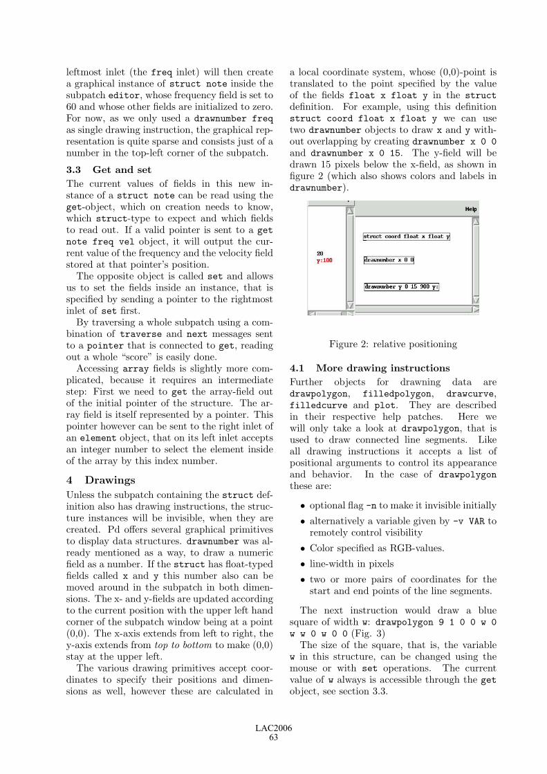
leftmost inlet (the freq inlet) will then createa graphical instance of struct note inside thesubpatch editor, whose frequency field is set to60 and whose other fields are initialized to zero.For now, as we only used a drawnumber freqas single drawing instruction, the graphical rep-resentation is quite sparse and consists just of anumber in the top-left corner of the subpatch.
3.3 Get and setThe current values of fields in this new in-stance of a struct note can be read using theget-object, which on creation needs to know,which struct-type to expect and which fieldsto read out. If a valid pointer is sent to a getnote freq vel object, it will output the cur-rent value of the frequency and the velocity fieldstored at that pointer’s position.
The opposite object is called set and allowsus to set the fields inside an instance, that isspecified by sending a pointer to the rightmostinlet of set first.
By traversing a whole subpatch using a com-bination of traverse and next messages sentto a pointer that is connected to get, readingout a whole “score” is easily done.
Accessing array fields is slightly more com-plicated, because it requires an intermediatestep: First we need to get the array-field outof the initial pointer of the structure. The ar-ray field is itself represented by a pointer. Thispointer however can be sent to the right inlet ofan element object, that on its left inlet acceptsan integer number to select the element insideof the array by this index number.
4 Drawings
Unless the subpatch containing the struct def-inition also has drawing instructions, the struc-ture instances will be invisible, when they arecreated. Pd offers several graphical primitivesto display data structures. drawnumber was al-ready mentioned as a way, to draw a numericfield as a number. If the struct has float-typedfields called x and y this number also can bemoved around in the subpatch in both dimen-sions. The x- and y-fields are updated accordingto the current position with the upper left handcorner of the subpatch window being at a point(0,0). The x-axis extends from left to right, they-axis extends from top to bottom to make (0,0)stay at the upper left.
The various drawing primitives accept coor-dinates to specify their positions and dimen-sions as well, however these are calculated in
a local coordinate system, whose (0,0)-point istranslated to the point specified by the valueof the fields float x float y in the structdefinition. For example, using this definitionstruct coord float x float y we can usetwo drawnumber objects to draw x and y with-out overlapping by creating drawnumber x 0 0and drawnumber x 0 15. The y-field will bedrawn 15 pixels below the x-field, as shown infigure 2 (which also shows colors and labels indrawnumber).
Figure 2: relative positioning
4.1 More drawing instructionsFurther objects for drawning data aredrawpolygon, filledpolygon, drawcurve,filledcurve and plot. They are describedin their respective help patches. Here wewill only take a look at drawpolygon, that isused to draw connected line segments. Likeall drawing instructions it accepts a list ofpositional arguments to control its appearanceand behavior. In the case of drawpolygonthese are:
• optional flag -n to make it invisible initially
• alternatively a variable given by -v VAR toremotely control visibility
• Color specified as RGB-values.
• line-width in pixels
• two or more pairs of coordinates for thestart and end points of the line segments.
The next instruction would draw a bluesquare of width w: drawpolygon 9 1 0 0 w 0w w 0 w 0 0 (Fig. 3)
The size of the square, that is, the variablew in this structure, can be changed using themouse or with set operations. The currentvalue of w always is accessible through the getobject, see section 3.3.
LAC200663

Figure 3: a blue square
4.2 PersistenceSaving a patch containing instances of datastructures will also save the created data struc-tures. Additionally it is possible to export thecurrent contents of a subpatch to a textfile bysending the message write filename.txt tothe subpatch’s receiver (described in 3.1) andread it back in using a similar read-message.
Such a persistence file contains a textual de-scription of the data structure templates andtheir current values, e.g. for our square-structure:
data;template square;float x;float y;float w;;;square 136 106 115;
5 Data structures in action
Instead of explaining all the features in detail,that data structures in Pd provide, I would liketo present some examples of how they have beenused.
5.1 Graphical scorePd’s data structures most naturally fit the needsof preparing and playing graphical scores. Inhis composion “Solitude”, north american com-poser and Pd developer Hans-Christoph Steinerused data structures to edit, display and se-quence the score. The graphical representationalso controls the sequencing of events. He de-scribes his approach in a post to the Pd mailinglist:4
4lists.puredata.info/pipermail/pd-list/2004-12/024808.html
The experience was a good combina-tion of visual editing with the mouseand text editing with the keyboard.The visual representation worked wellfor composition in this style. [My]biggest problem was finding a way torepresent in the score all of the thingsthat I wanted to control. Since Iwanted to have the score generate thepiece, I did not add a couple features,like pitch shifting and voice allocationcontrol, which I would have liked tohave.
Both the Pd patch (Fig. 4) and a recording of“Solitude” are available at the composer’s web-site.5
Figure 4: Score for “solitude” by Hans-Christoph Steiner
5.2 Interaction“Solitude” changes the data stored inside astructure only during the compositional phase,but not in the performance of the piece. An ex-ample, where data structures are manipulated“on the fly” is the recreation of the classic videogame “PONG” by the author6, as shown inFig. 5.
This simple piece uses the ratio of the currentscore in the game (1/2 in Fig. 5) to influence afractal melody played in the background. Thex-position of the ball is read out by a get-objectto pan the stereo position of the melody.
5.3 GUI-buildingData structures also are useful to implementcustom GUI elements for Pd. A collection of
5at.or.at/hans/solitude/6footils.org/cms/show/27
LAC200664

Figure 5: “PONG” by Frank Barknecht
these is currently built by Chris McCormick.7Figure 6 shows an envelope generator and apattern seqencer of variable length, that can bereused several times in a patch.
Figure 6: Two GUI objects by Chris Mc-Cormick
5.4 VisualisationMany advanced concepts in computer music ordigital art in general deal with rather abstract,often mathematical issues. Data structures canhelp with understanding these concepts by con-necting the abstract with the visible world.
The german composer Orm Finnendahl cre-ated such interactive Pd patches using datastructures to explain things like the samplingtheorem or granular synthesis.
With his patches “pmpd-editor” and “msd-editor” (Fig. 7) the author of this paper wrotetools to explore particle systems (masses con-nected by springs) interactively. A user cancreate the topology for a particle system and
7mccormick.cx/viewcvs/s-abstractions/
Figure 7: Editor for mass-spring-damper-topologies by Frank Barknecht
animate it directly inside the Pd patch. Vari-ous helper functions provide means for import-ing and exporting such topologies to be used inother applications as 3D-modellers for example.The particle systems designed with the editorcan also generate control data to influence var-ious synthesis methods. The editor is availablein the CVS repository of the Pure Data devel-oper community at pure-data.sf.net.
5.5 IllustrationFinally we get back to another original motiva-tion for writing Pd in the first place. In (Puck-ette, 1996) Puckette writes:
Pd’s first application has been to pre-pare the figures for an upcoming sig-nal processing paper by Puckette andBrown.
Almost a decade later, Puckette is still usingPd to illustrate paper, this time for his bookproject “Theory and Techniques of ElectronicMusic”.8
All graphics in this book were made using Pditself, like the one shown in Fig. 8.
6 Conclusion
This paper could only give a short introduc-tion to Pd’s data structures. As always they
8So far only available online at: crca.ucsd.edu/~msp/techniques.htm
LAC200665

Figure 8: Illustration courtesy by M. Puckettefrom his book: “Theory and Techniques of Elec-tronic Music”
are best learned by studying examples. Pdcomes with documentation patches that can beedited and changed. Most patches that usedata structures are collected in the directory“doc/4.data.structures” of the Pd documenta-tion. The HTML-manual of Pd contains furtherinformation in chapter “2.9. Data structures“.9
Pd’s data structures are powerful tools thatcan greatly enhance the possibilities of Pd. Insome areas they still are a bit awkward to usethough. For example animating large numbersof data structures may influence audio gener-ation and even lead to dropped samples andclicks. There also still are issues with provid-ing a smooth framerate. In the author’s viewdata structures thus cannot replace specializedextensions like Gem in this regard yet. If theyshould try to do so at all, remains an open ques-tion.
However problems like this can only be foundand fixed, if more artists and musicians in thePd community will actually use them—a classi-cal chicken and egg problem. Thus it is hopedthat this paper will create more interest in PureData’s data structures.
9www-crca.ucsd.edu/~msp/Pd_documentation/
7 Acknowledgements
References
M. Puckette. 1996. Pure data: another inte-grated computer music environment. In Proc.the Second Intercollege Computer Music Con-certs, pages 37–41.
M. Puckette. 2002. Using pd as a score lan-guage. In ICMC Proceedings, pages 184–187.
LAC200666

A Sample Accurate Triggering System for Pd and Max/MSP
Eric LyonMusic - School of Arts, Histories and Cultures
The University of ManchesterMartin Harris Building
Coupland StreetManchester, M13 9PL
United Kingdom,[email protected]
AbstractA system of externals for Pd and Max/MSP is de-scribed that uses click triggers for sample-accuratetiming. These externals interoperate and can alsobe used to control existing Pd and Max/MSP exter-nals that are not sample-accurate through conver-sion from clicks to bangs.
KeywordsComputer Music, Drum Machines, Max/MSP, Pd,Sample Accurate Timing
1 Introduction
In the world of experimental electronic music,regular pulsation has often been frowned upon.During an exchange of ideas between KarlheinzStockhausen and several younger electronic mu-sicians (Witts 1995) Stockausen observed, ”Iheard the piece Aphex Twin of Richard Jamescarefully: I think it would be very helpful if helistens to my work Song Of The Youth, whichis electronic music, and a young boy’s voicesinging with himself. Because he would then im-mediately stop with all these post-African rep-etitions, and he would look for changing tempiand changing rhythms, and he would not allowto repeat any rhythm if it were varied to someextent and if it did not have a direction in itssequence of variations.” Richard D. James re-sponded from a different perspective, ”I didn’tagree with him. I thought he should listen toa couple of tracks of mine: ”Didgeridoo”, thenhe’d stop making abstract, random patterns youcan’t dance to.”
2 The Need for Better Timing
The same year this interview was published, Iattempted to use a pre-MSP version of Max tocontrol a drum machine I had built in Kyma.This experiment also resulted in ”random pat-terns you can’t dance to,” since the Max eventscheduler at the time was good enough for cer-tain kinds of algorithmic music, yet not sta-ble enough for techno music. Ten years later,
the event schedulers for both Max/MSP andPd are much more stable, and are quite usablefor some forms of music based on regular pul-sation. However, their performance is still sub-ject to variability based on factors such as thesignal vector size and competition from control-level events. Furthermore, the scheduling sys-tems of Max/MSP and Pd differ such that thetiming behavior of similar patches can performquite differently between the two systems. TheMax/MSP event scheduler is prone to perma-nently drift from a sample accurate measure-ment of timing. The underlying Pd event sched-uler is better than sample-accurate, though ap-parently at the cost of a higher likelihood ofinterruption of the audio scheduler, resultingin audible glitches. In both systems temporalaccuracy of control-level events can drift freelywithin the space of a signal vector.
2.1 The Problem with Small TimeDeviations
Even when the amount of deviation from sampleaccuracy is not clearly noticeable at a rhyth-mic level, it may still have undesirable musi-cal effects. For example, a pulsation may feelnot quite right when there are a few 10s ofmilliseconds of inaccuracy in the timing frombeat to beat. Even smaller inaccuracies, thoughrhythmically acceptable, can still cause prob-lems when sequencing sounds with sharp tran-sients, since changes in alignment on the orderof a couple of milliseconds will create differentcomb filtering effects as the transients slightlyrealign on successive attacks. This is a partic-ularly insidious artifact since many users mightnot think to trace a spectral effect to a systemtiming flaw.
3 Sketch of a Solution
One way to sidestep the abovementioned prob-lems is to program trigger scheduling at thesample level, rather than at the event level at
LAC200667

which bangs perform. This scheduling must bebuilt into every external that is to benefit fromsample accurate triggering. In order to be ofmuch use, such externals must be able to easilysynchronize with each other. I have developed asystem of externals based on click triggers. Thetrigger signal contains a non-zero value at everysample where a trigger is to be sent, and zerosat all other samples. The click trigger can con-vey one additional piece of information to itsreceiver, such as desired amplitude.
4 Sample Accurate Metronomes
The centerpiece of the system is an exter-nal that coordinates multiple metronomes. Itis called samm~ (for sample accurate multiplemetronomes). The first argument to samm~ isthe tempo in BPM, followed by a series of beatdivisors that each define the metronome speedfor a corresponding outlet. For example, the ar-guments 120 1 2 3 7 would activate four outlets,all beating at 120 BPM, the first at a quarternote, the second at an eighth note, the thirdat an eighth note triplet and the fourth at asixteenth note septuplet. Any of these param-eters can have fractional components, and thebeat divisors may be less than 1.0 (resulting inbeat durations greater than a quarter note). Aclick trigger from samm~ is always a sample withthe value 1.0. The tempo can be varied duringperformance while preserving proportional rela-tions among all beat streams.
4.1 Alternative MetronomeSpecifications
For convenience, several different methods areprovided for specifying metronome tempi . Anew set of beat divisors may be specified withthe message ”divbeats.” Beat durations may bespecified directly in milliseconds with the mes-sage ”msbeats.” Beats may be specified in sam-ples (useful if tempi need to be built around asoundfile in terms of its length in samples) withthe message ”sampbeats.” Finally beat dura-tions may be specified with ratio pairs (withthe denominator representing a division of awhole note) using the message ”ratiobeats.”The message ”ratiobeats 1 4 3 16 5 28” speci-fies relative beat durations of respectively aquarter note, a dotted eighth note and five sep-tuplets. Fractions may be employed to repre-sent more complex ratios, though it is proba-bly simpler in that case to represent such ratioswith decimal numbers and use the ”divbeats”message.
5 Pattern Articulation
The beat streams from samm~ can be pat-terned into arbitrary rhythms with anotherexternal called mask~. This external storesa sequence of numbers, which are sent outin cyclic series in response to click triggers.An initial series is given as a set of argu-ments to mask˜. For example, the arguments1 0 0 0 1 0 0 0 1 0 0 0 1 0 1 0 could serve to de-fine a rhythmic pattern for a single instrumentin a drum machine, in this case perhaps a kickdrum. Since zeros cannot trigger an attack, anyzero in a mask~ pattern will convert an incom-ing beat to a rest. Since any non-zero num-ber can serve as a trigger, the attacks need notall have value ”1” but could specify differentamplitudes instead. Multiple mask~ instancescould control different parameters of the sameevent, all sample-synched. Since mask~ patternscan be of any size (up to 1024 members), dif-ferent sized mask~ patterns will cycle in andout of phase with each other, which is desir-able in a poly-metric scheme. It is also possiblefor two mask~ patterns of the same size to beout of sync with each other if, for example, onemask~ was created later in the design of a givenpatch. This loss of sync is usually not desirable.Thus, mask~ provides an option whereby theinput is interpreted not as triggers, but ratheras index numbers used to iterate through themask~ pattern. Using the same indexing clicks(generated from another mask~ of course) guar-antees that all patterns so controlled remainlocked in phase. Any mask~ external can holda large number of different patterns which maybe stored and recalled during performance.
6 Sample Accurate Synthesizers
Sample accurate externals are provided forsound production through both sampling andsynthesis. adsr~, an external that is alreadypart of my Web-published Max/MSP externalset LyonPotpourri (Lyon 2003)is an ADSR en-velope generator. I have retrofitted adsr~ torespond to click triggers, interpreting the valueof the click as the overall amplitude of the en-velope. Any software synthesis algorithm thatuses adsr~ as an envelope can now be triggeredwith sample accuracy.
7 Sample Accurate Samplers
A sample playback external called player~ isprovided, which plays back a sample stored in abuffer (for Max/MSP) or an array (for Pd). The
LAC200668

two parameters to player~ are amplitude andplayback increment, sent as signals to the firstand second inlets respectively. Amplitude is al-ways a click trigger. Under normal conditions,playback increment is a signal that can be ma-nipulated during performance. An alternativestatic increment mode is provided, called by the‘static increment’ message, in which the play-back increment is also received as a click trig-ger, which persists throughout the note play-back without variation.
7.1 Polyphonic Nature of player˜One important feature was added for conve-nience - player~ is polyphonic (up to 16 voicesat present, though this limit may be opened upto the user as a parameter in a later version).An inconvenient feature of groove~, tabosc4~,et. al. is that if a note is currently active when anew playback trigger arrives, the current note isinstantly truncated which often creates discon-tinuities. In player~, all currently active notescontinue playing to the end of their buffers, evenas new attack triggers arrive. This is muchmore convenient than having to create a polystructure for every member of a drum machine.This is also the reason for the static incrementmode. In static increment mode multiple in-stances of playback can proceed at differentplayback increments, which is quite handy forcreating polyphony from a single sample.
8 Putting the Pieces Together - aSimple Drum Machine
Now let’s look at an example of how the exter-nals described thus far can be combined. (SeeFigure 1.) A samm~ unit with a tempo of 120BPM creates two beat streams, the first divid-ing the quarter by two (eighth-notes) and thesecond dividing the quarter by four (sixteenth-notes). Two player~ objects play back sam-ples stored in two arrays. The bdbuf player~takes its metronome from the eighth-note beatstream. Its attack/amplitude pattern is storedin the mask~ object directly above it. The incre-ment is fixed at 1.0, taken from a sig~ object.The output is scaled and sent to the DACs.
8.1 Polyrhythmic SequencingThe hihat structure is slightly more compli-cated than that of the bass drum. The beatstream is sixteenth-notes in all cases. The du-ration of the attack/amplitude pattern is onebeat, rather than the four beats of the bassdrum pattern. But a second pattern with a
Figure 1: A two voice drum machine.
periodicity of three sixteenth-notes controls theincrement from a second mask~ object routedto the second (increment) inlet of the hatbufplayer~. A third rhythmic level is added asthe hihat output is ring-modulated by the sinewave output of an osc~ object. The osc~ iscontrolled by a frequency pattern with a peri-odicity of five sixteenth-notes. A custom ob-ject, clickhold~is inserted between the mask~and the osc~ to sample and hold each click asit comes in, resulting in the sustained frequencysignal required by osc~. As the three differentpatterns go in and out of phase with each other,a composite 15-beat pattern emerges. Morecomplex polyrhythmic arrangements are easilyimagined, especially to control various parame-ters of synthesis algorithms rather than the rel-atively simple sample playback.
8.2 You Call That a Drum Machine?
It is quite clear that the Pd patch shown in Fig-ure 1 does not look anything like a conventionaldrum machine. Of course it is possible to usesome graphical objects to wire up an interfacethat that looks more like a drum machine andserves as a front end, generating patterns forthe mask~ objects. But this sort of tidy front
LAC200669

end would also limit our possibilities. The verylooseness of the scheme of distributed mask~ ob-jects suggest more fluid ways of thinking aboutdrum patterns, and manipulating them duringperformance.
9 dmach˜ - an Integrated DrumMachine External
The combined use of samm~ and mask~ can cre-ate arbitrarily complex rhythms. However cer-tain kinds of rhythms are somewhat inconve-nient to specify under this model. Consider a4/4 bar pattern where the first beat is dividedinto 16th notes, the second beat into triplets,and the last two beats divided into eighth-note quintuplets. A representation of this pat-tern requires three different beat streams andthree different mask˜ objects. In order to ad-dress this problem, a proof-of-concept exter-nal called dmach~ has been designed. dmach~contains an internal clock, and stores user-specified patterns. The patterns are sent asoutlet pairs; dmach~ is designed to send bothattack patterns and increment patterns. Thesepatterns can be recalled at will during the per-formance. The current pattern is looped untilsuch time as a new one is recalled. Patternsare stored with the ’store’ message and recalledwith the ’recall’ message. The current patternis played to completion before a new pattern isloaded, thus guaranteeing a sample-synced per-formance. The last outlet of dmach~ sends aclick at the start of each pattern playback, mak-ing it easy for the user to build a sequencer forstored patterns.
9.1 Pattern Specification for dmach˜Pattern specification in dmach~ allows for arbi-trary bar sizes and arbitrary subdivisions withinthe bar. Patterns are entered into dmach~ withthe ’store’ message. The first two parametersare the pattern number and the number of beatsin the bar. The pattern number is an integerwhich will be used to recall the pattern. Thenumber of beats is defined as the number ofquarter notes in a bar. A specification of 4 cre-ates a 4/4 bar. A 3/8 bar would be specifiedwith a bar duration of 1.5. Following are a se-ries of beat patterns, each one targeted towarda different instrument. The first parameter isthe designated instrument. (Instrument 0 hasits beat stream come out of the first outlet, andits increment stream out of the second outletof dmach~.) Next is a beat duration represent-ing a segment of the bar. If the entire beat
Figure 2: A dmach~ two voice drum machine.
pattern shares a single subdivision of the beat,then this segment would simply be the same asthe bar duration. However since an arbitrarynumber of segments can be specified (on con-dition that they eventually add up to preciselythe bar duration), an arbitrary rhythmic sub-division of the bar is possible, which could bequite complex. Following the segment durationis the segment subdivision factor. This subdi-vision must be an integer. Following this is anattack pattern that must have the same num-ber of elements as the subdivision factor justspecified. Following the attack pattern is theincrement pattern. The increment pattern hasthe same number of elements as non-zero at-tacks in the attack pattern. In other words,increments are specified only for attacks, notfor rests. Additional segments are identicallyspecified until the duration of the bar is filled.This process is repeated for every instrumentalbeat/increment stream required for the pattern.Data is only required for instruments that playin a given pattern. A pattern with no instru-ment data functions as a bar of rest.
9.2 Usability of dmach˜
As mentioned above, dmach~ is a proof-of-concept external. Complete error checking onuser input to dmach~ is a thankless task thathas not yet been undertaken, thus it is presentlyeasy to crash dmach~ with bad data, taking
LAC200670

down Pd or Max/MSP with it. Given the in-tricacy of the data format, it is recommendedthat a preprocessor be used to generate the datafrom a more user-friendly interface than typingraw data by hand. It is interesting to considerwhat might be a suitable graphical interface todesign patterns for dmach~ though such consid-erations are beyond the scope of this paper. Thecomplexity of pattern specification for dmach~,while potentially burdensome, is also necessaryin order to obtain full rhythmic flexibility. In-deed this flexibility goes considerably beyondwhat is possible with most commercial drummachines. However as mentioned above, theuser can be buffered from this complexity witha suitable interface, at the cost of some loss offlexibility in pattern design. As can be seen inFigure 2, the data complexity is localized in the’store’ messages, so the patching structure forwiring up a drum machine in Pd with dmach~is somewhat simpler than in the earlier examplewith multiple mask~ objects.
9.3 Relative Inflexibility of dmach˜
While it is convenient to bind increment pat-terns to attack patterns in dmach˜ this arrange-ment is somewhat inflexible. The user mightprefer not to control increment, or to controlincrement out of sync (or even randomly) inwhich case the additional outlets for incrementbecome superfluous, as does the burden of spec-ifying increment pattern in the ’store’ messages.On the other hand, one might well wish to si-multaneously control parameters other than orin addition to increment, such as pan location,filter parameters, ring modulation frequency ormultiple synthesis parameters, if a software syn-thesizer is being driven by a particular dmach~beat stream.
9.3.1 Increasing Flexibility for dmach˜A simple method to increase the flexibility ofdmach~ would use the second beat stream outletto send attack index numbers which could thenbe used to control multiple mask~ objects. Thiswould give full flexibility, though the patterndata would in most cases be spread over mul-tuple mask~ objects. In some cases this couldbe an advantage since individual data streamscould be changed independently during perfor-mance. A more complicated solution would al-low the user to specify the structure of a givendmach~ object through its creation arguments,such that a given beat pattern could have an ar-bitrary number of outlets in addition to its at-
tack pattern outlet. This would keep all the pat-tern data in a single ’store’ message. Howeverthe complexity of maintaining data in this form,along with the possibility of eventually bump-ing up against the hard limit on the numberof atoms allowed in a Max/MSP or Pd messagebox, might make this solution unwieldy in prac-tice. However a sufficiently flexible graphical in-terface that could create and manage the datain the ’store’ messages with arbitrary structure,might make this approach worth pursuing. Asmentioned above, dmach~ is still a prototypeobject, which is not yet ready for prime-time.However dmach~ does raise interesting questionsabout structuring control data within the sam-ple accurate triggering system under discussion.
10 Interoperation with SampleInaccurate Externals
Many useful externals exist in Pd andMax/MSP which do not currently provide sam-ple accurate response to triggers. In orderto utilize such externals in the system pre-sented here, they must be triggered with abang synchronized to the incoming click trigger.Max/MSP makes this quite easy to do via theedge~ external which sends bangs on changesfrom one to zero. Since edge~ is only avail-able for Max/MSP, a custom external calledclick2bang~ has been designed to send out abang in response to an incoming click. The bangcan only be accurate to within the size of thesignal vector. However the receiver can be iso-lated in a sub-patch with a signal vector size setto 1 by the block~ object, forcing that part ofthe patch back to sample accuracy.
11 Clicks and Continuity
While click triggers are conceptually simple andthus easy to work with in designing patches,they do have one disadvantage. Once sent thereis no further information on the progress of atriggered process until the next click is received.For the types of data discussed here this is not aproblem. However certain continuous processessuch as filter sweeps might need to be corre-lated to the progress of a given time span. Formost practical purposes a line or line~ objecttriggered by an appropriate message (itself trig-gered by a click2bang~) will suffice. Howeverit would be fairly easy to design an external thatoutputs precise continuous data in response toclick triggers. We might call such an externalclickline~ which would receive a target value
LAC200671

and the duration over which to interpolate froma stored initial value to the target value, withall data sent as clicks.
12 Conclusions and Future Work
The click trigger model has proved easy to im-plement, useful for designing rhythmic patchesin Pd and Max/MSP and enables a degree oftiming precision for rhythmic events that is notgenerally practical for Pd and Max/MSP. I planto incorporate this model into any future exter-nals I design. In the spirit of generosity, I willsuggest future work for others as well as for my-self. There has been increased interest in theMax/MSP community for sample-accurate tim-ing. Some more recent (and recently updated)Max/MSP object such as sfplay~ and techno~employ sample-accurate triggering, albeit gen-erally using more complicated methods than theclick triggering system described here. It wouldbe nice to see a unified sample-accurate trigger-ing system employed to encompass the manyPd and Max/MSP externals that could benefitfrom it, such as tabplay~ and groove~. Thirdparty developers of externals might also findthis model useful for any of their objects thatinvolve triggering. Finally, all of the work de-scribed here is based on steady pulses. Howeverit would be interesting to develop metronomesthat implement arbitrary tempo curves, whichwould also output click triggers. This would al-low for sample-accurate exploration of a verydifferent class of rhythms.
13 Acknowledgements
Thanks to Peter Castine for a brief Internetdiscussion on the numerical accuracy of doublefloating point variables, confirming my calcula-tion that samm~ will keep all of its metronomessample-synched indefinitely for any practicalmusical performance, given current human life-spans. Thanks also to the two anonymous LACreviewers for helpful comments and suggestionson the first draft of this paper.
References
Lyon, Eric. LyonPotpourri, a Collectionof Max/MSP externals. 2003. Dart-mouth College. Accessed 3 Jan. 2006.<http://arcana.dartmouth.edu/~eric/MAX/>.
Witts, Dick. ”Advice to Clever Children/Advicefrom Clever Children.” The Wire Nov. 1995:33+.
LAC200672

Scripting Csound 5
Victor Lazzarini Music Technology Laboratory
National University of Ireland, Maynooth [email protected]
Abstract
This article introduces a scripting environment for Csound 5. It introduces the Csound 5 API and discusses it use in the development of a TclTk scripting interface, TclCsound. The three components of TclCsound are presented and discussed. A number of applications, from simple transport control of Csound to client-server networking are explained in some detail. The article concludes with a brief overview of some other Csound 5 language APIs, such as Java and Python.
Keywords: Music Programming Languages; Scripting Languages; Computer Music Composition.
1 Introduction
The Csound music programming system (Vercoe 2004) is currently the most complete of the text-based audio processing systems in terms of its unit generator collection. Csound hails from a long tradition in Computer Music. Together with cmusic (Moore 1990), it was one of the first modern C-language-based portable sound compilers (Pope 1993), when it was released in 1986. Due to its source-code availability, first from the cecelia MIT ftp server and then from the DREAM site at Bath, it was adopted by composers and developers world-wide. These brave new people helped it to develop into a formidable tool for sound synthesis, processing and computer music composition. Its latest version, Csound 5 (ffitch, 2005) has close to one thousand opcodes, ranging from the basic table lookup oscillator to spectral signal demixing unit generators. Many important changes have been introduced in Csound5, which involved a complete redesign of the software. This resulted not only in a better software, from an engineering perspective, but in the support for many new possible ways of using and interacting with Csound.
An important development has been the availability of a complete C API (the so-called ‘Host API’, which was, in fact, already partially present in earlier versions). The API can be used to instantiate and control Csound from a calling process, opening a whole new set of possibilities for the system.
2 The Csound 5 API
The Csound 5 Host API allows the embedding of the audio processing system under other ‘host’ software. Effectively, Csound is now a library, libcsound, that can provide audio services, such as synthesis and processing, for any application. This allows for complete control over the functioning of the audio engine, including transport control, loading of plugins, inter-application sofware bus, multithreading, etc.. A ‘classic’ csound command-line program can now be written based only on a few API calls: #include <csound.h> int main(int argc, char **argv) { int result; CSOUND *cs; /* the csound instance */ /* initialise the library */ csoundInitialize(&argc, &argv, 0); /* create the csound instance */ cs = csoundCreate(NULL); /* compile csound code */ result = csoundCompile(cs, argc, argv); /* this is the processing loop */ if(result) while(csoundPerformKsmps(cs)==0); /* destroy the instance */ csoundDestroy(cs); return 0; }
The Csound API can be used in many applications; the development of frontends is the most obvious of these. A good example of its application is found on the csoundapi~ Class, which provides a multi-instantiable interface to Csound 5 for Pure Data. The Csound API is the basis for TclCsound (Lazzarini 2005), a Tcl/Tk extension, discussed in the next section.
LAC200673

3 TclCsound
The classic interface to csound gives you access to the program via a command-line such as csound -odac hommage.csd
This is a simple yet effective way of making sound. However, it does not give you neither flexibility nor interacion. With the advent of the API, a lot more is possible. At this stage, TclCsound was introduced to provide a simple scripting interface to Csound. Tcl is a simple language that is easy to extend and provide nice facilities such as easy file access and TCP networking. With its Tk component, it can also handle a graphic and event interface. TclCsound provides three ‘points of contact’ with Tcl: 1. a csound-aware tcl interpreter (cstclsh) 2. a csound-aware windowing shell (cswish) 3. a csound commands module for Tcl/Tk (tclcsound dynamic lib)
3.1 The Tcl interpreter: cstclsh
With cstclsh, it is possible to have interactive control over a csound performance. The command starts an interactive shell, which holds an instance of Csound. A number of commands can then be used to control it. For instance, the following command can compile csound code and load it in memory ready for performance: csCompile -odac hommage.csd -m0 Once this is done, performance can be started in two ways: using csPlay or csPerform. The command csPlay
will start the Csound performance in a separate thread and return to the cstclsh prompt. A number of commands can then be used to control Csound. For instance, csPause
will pause performance; and csRewind
will rewind to the beginning of the note-list. The csNote, csTable and csEvent commands can be used to add Csound score events to the performance, on-the-fly. The csPerform command, as opposed to csPlay, will not launch a separate thread, but will run Csound in the same thread, returning only when the performance is finished. A
variety of other commands exist, providing full control of Csound.
3.2 Cswish: the windowing shell
With Cswish, Tk widgets and commands can be used to provide graphical interface and event handling. As with cstclsh, running the cswish command also opens an interactive shell. For instance, the following commands can be used to create a transport control panel for Csound: frame .fr button .fr.play -text play -command csPlay button .fr.pause -text pause -command csPause button .fr.rew -text rew -command csRewind pack .fr .fr.play .fr.pause .fr.rew Similarly, it is possible to bind keys to commands so that the computer keyboard can be used to play Csound. Particularly useful are the control channel commands that TclCsound provides. For instance, named IO channels can be registered with TclCsound and these can be used with the invalue, outvalue opcodes. In addition, the Csound API also provides a complete software bus for audio, control and string channels. It is possible in TclCsound to access control and string bus channels (the audio bus is not implemented, as Tcl is not able to handle such data). With these TclCsound commands, Tk widgets can be easily connected to synthesis parameters.
3.3 A Csound server
In Tcl, setting up TCP network connections is very simple. With a few lines of code a csound server can be built. This can accept connections from the local machine or from remote clients. Not only Tcl/Tk clients can send commands to it, but TCP connections can be made from other sofware, such as, for instance, Pure Data (PD). A Tcl script that can be run under the standard tclsh interpreter is shown below. It uses the Tclcsound module, a dynamic library that adds the Csound API commands to Tcl. # load tclcsound.so #(OSX: tclcsound.dylib, Windows: tclcsound.dll) load tclcsound.so Tclcsound set forever 0 # This arranges for commands to be evaluated proc ChanEval { chan client } { if { [catch { set rtn [eval [gets $chan]]} err] } { puts "Error: $err" } else { puts $client $rtn flush $client } } # this arranges for connections to be made
LAC200674

proc NewChan { chan host port } { puts "Csound server: connected to $host on port $port ($chan)" fileevent $chan readable [list ChanEval $chan $host] } # this sets up a server to listen for # connections set server [socket -server NewChan 40001] set sinfo [fconfigure $server -sockname] puts "Csound server: ready for connections on port [lindex $sinfo 2]" vwait forever
With the server running, it is then possible to set up clients to control the Csound server. Such clients can be run from standard Tcl/Tk interpreters, as they do not evaluate the Csound commands themselves. Here is an example of client connections to a Csound server, using Tcl: # connect to server set sock [socket localhost 40001] # compile Csound code puts $sock "csCompile -odac hommage.csd" flush $sock # start performance puts $sock "csPlay" flush $sock # stop performance puts $sock "csStop" flush $sock
As mentioned before, it is possible to set up clients using other software systems, such as PD. Such clients need only to connect to the server (using a netsend object) and send messages to it. The first item of each message is taken to be a command. Further items can optionally be added to it as arguments to that command.
3.4 A Scripting Environment
With TclCsound, it is possible to transform the popular text editor e-macs into a Csound scripting/performing environment. When in Tcl mode, the editor allows for Tcl expressions to be evaluated by selection and use of a simple escape sequence (ctrl-C ctrl-X). This facility allows the integrated editing and performance of Csound and Tcl/Tk code. In Tcl it is possible to write score and orchestra files that can be saved, compiled and run by the same script, under the e-macs environment. The following example shows a Tcl script that builds a csound instrument and then proceeds to run a csound performance. It creates 10 slightly detuned parallel oscillators, generating sounds similar to those found in Risset’s Inharmonique.
load tclcsound.so Tclcsound # set up some intermediary files set orcfile "tcl.orc" set scofile "tcl.sco" set orc [open $orcfile w] set sco [open $scofile w] # This Tcl procedure builds an instrument proc MakeIns { no code } { global orc sco puts $orc "instr $no" puts $orc $code puts $orc "endin" } # Here is the instrument code append ins "asum init 0 \n" append ins "ifreq = p5 \n" append ins "iamp = p4 \n" for { set i 0 } { $i < 10 } { incr i } { append ins "a$i oscili iamp, ifreq+ifreq*[expr $i * 0.002], 1\n" } for { set i 0 } {$i < 10 } { incr i } { if { $i } { append ins " + a$i" } else { append ins "asum = a$i " } } append ins "\nk1 linen 1, 0.01, p3, 0.1 \n" append ins "out asum*k1" # build the instrument and a dummy score MakeIns 1 $ins puts $sco "f0 10" close $orc close $sco # compile csCompile $orcfile $scofile -odac -d -m0 # set a wavetable csTable 1 0 16384 10 1 .5 .25 .2 .17 .15 .12 .1 # send in a sequence of events and perform it for {set i 0} { $i < 60 } { incr i } { csNote 1 [expr $i * 0.1] .5 \ [expr ($i * 10) + 500] [expr 100 + $i * 10] } csPerform # it is possible to run it interactively as # well csNote 1 0 10 1000 200 csPlay
The use of such facilities as provided by e-macs can emulate an environment not unlike the one found under the so-called ‘modern synthesis systems’, such as SuperCollider (SC). In fact, it is possible to run Csound in a client-server set-up, which is one of the features of SC3. A major advantage is that Csound provides about three or four times the number of unit generators found in that language (as well as providing a lower-level
LAC200675

approach to signal processing, in fact these are but a few advantages of Csound).
3.5 TclCsound as a language wrapper
It is possible to use TclCsound at a slightly lower level, as many of the C API functions have been wrapped as Tcl commands. For instance it is possible to create a ‘classic’ Csound command-line frontend completely written in Tcl. The following script demonstrates this: #!/usr/local/bin/cstclsh set result 1 csCompileList $argv while { $result != 0 } { set result csPerformKsmps } This script is effectively equivalent to the C program shown in section 2. If saved to, say, a file called csound.tcl, and made executable, it is possible to run it as in csound.tcl –odac hommage.csd
4 OTHER LANGUAGE WRAPPERS
It is very likely that many users will prefer to run Csound from their programming environment of choice. For these, C++, Lisp (using CFFI), Java and Python are other available languages. Access to the Csound library is provided by SWIG-generated wrappers.
4.1 Python and Java examples
The way these languages interact with the Csound 5 library is very similar to the C API. A major difference is that they are require to import the Csound module (based on a ‘native’ library module), called csnd. In Python, the csnd.py and csnd.pyc files, distributed with Csound, hold the Python API, whereas in Java, the csnd.jar archive holds the csnd package. Generally, for a straight performance, the steps involved are: 1. Create a Csound instance:
Java: cs = new Csound();
Python: cs = csnd.csoundCreate(None);
2. Compile Csound code: Java:
cs.Compile(“hommage.csd”); Python: csnd.csoundCompile(cs, 2, [‘csound’, ‘hommage.csd’]) 3. Run a processing loop: Java: int result; while(result == 0) result = cs.PerformKsmps(); Python: while result == 0: result =csoundPerformKsmps(cs); 4. Clean up, ready for a new performance: Java: cs.Reset(); Python: csnd.csoundReset(cs); The Java and Python wrappers open up many new possibilities for using Csound programmatically. There are, though, a few aspects of the C API, which are very C-specific and do not translate into Java or Python. However, these should not make any impact on the majority of the applications that the system might have. 5. Conclusion and Future Prospects Csound is a very comprehensive synthesis and musical signal processing environment. The additional facilities provided in its latest version have brought it up-to-date with more modern software engineering concepts. Its existence as a library has enabled a variety of new uses and added new ‘entry-points’ into the system. It is very likely that such enhancements will also spur further features, esp. when the new parser for the language, under development by John ffitch, is introduced. It will then be possible to develop other ways of interacting with the system, such as alternative synthesis languages, interpreters and further facilities for networking and distributed operation.
5 References
John ffitch. On the design of Csound 5.
Proceedings of the 2005 Linux Audio Conference,ZKM, Karlsruhe, Germany.
LAC200676

Victor Lazzarini. The TclCsound frontend and language Wrapper. Sounds Electric 2005. NUI, Maynooth, Ireland.
F Richard Moore. 1990. Elements of Computer Music, Englewood Cliffs, NJ: Prentice-Hall, 1990.
Stephen T Pope. 1993. Machine Tongues XV: Three Packages for Software Sound Synthesis. Computer Music Journal 17 (2).
Barry Vercoe et Al. 2005. The Csound Reference Manual.
http://www.csounds.com/manual/html/index.html
LAC200677

LAC200678

Linux and music out of the box
Hartmut NOACKwww.linuxuse.de/snd
Max-Steinke-Strasse 2313086 Berlin,
AbstractThe perception of Linux audio softwareamongst so-called ”average musicians” withno ”geek”background is not as positive as it couldbe. Many musicians still think that there is notenough usability and too little Linux softwareavailable to produce an album. This proposalintroduces design studies for a user interface dedi-cated to a Linux Audio Workstation (LAW) thatI intend to build based on standard PC hardware.The interface intends to integrate all the mainvirtues of Linux audio software in a logical andself explanatory way, without encumbering theirflexibility, to provide the same level comfort andintuitive operation as offered by suites such asSteinberg’s Cubase. There will be no install-CD tobe downloaded, as offered by Distros like Demudi orAgnula, but only some useful scripts and LFS-styledocumentation to enable people to rebuild the boxitself if they wish to do so.
Keywordsusability, integration, suite, interface, workstation
1 Introduction
Musicians often state that they don’t know verymuch about computers, that they only want touse these boxes and that they have neither thetime nor motivation to learn how a computeror software works. Proprietary software ven-dors try to adapt to such attitudes by design-ing all-in-one applications, such as Steinberg’sCubase, with simple-looking interfaces and au-tomatic setup assistants that leave power usageand fine tuning to the experienced users andhide possible options and - of course - the sourcecode from the ”end user” to keep their productsunder control and consistent.
This is not the way that Linux audio can go,since it is open source. Free software authors, aswell as the distributors, need to develop otherways to achieve usability and a trustworthinessthat meets the needs of productive use. Thiscan be done if the whole audio workstation is de-veloped and built as an integrated combination
of software and hardware components, that fittogether and are Linux compatible down to thelast screw.
Some may ask:
is this still possible without charg-ing the users for software ?
we say: It is! - if we find a way to charge theusers for integration and support... it is our be-lief that the time is nigh to make people investin free audio software development. People likePaul Davis, Taybin Rutkin or Werner Schweershould be rewarded for their work. We believethat a reasonable part of the revenue that couldbe generated with oss-based audio workstationsshould go directly to the developers of the mostimportant software for these boxes - especiallyif these developers do not yet receive any rea-sonable financial support.
To make sure that the system as a wholeworks flawlessly enough for studio use, it willbe necessary to setup and test each box by handbefore shipping. We did so in Suse 9.3 to buildthe first prototype - on the second box, thatwe plan to build in June, it will be done withUbuntu including packages from the Ubuntustudio metadistribution. The project does notintend to add another distribution, toolbox orfile format to the already existing mass of exper-iments in Linux audio - we only want to helpothers using all the great stuff that is alreadythere. So all scripts will be native, averagebash-syntax and XML as used in xfce4. TheLAW itself will be built, set up and tuned byhand, the scripts will be usable in every Linux-environment that has xfce4 and the incorpo-rated applications.
2 plans and sketches
Most users coming from proprietary tools, suchas Steinberg Nuendo or SEKD Samplitude, havea rather ambivalent impression of the systemwhen looking at Linux solutions. On the one
LAC200679

hand they like tools such as Jamin or snd, buton the other hand they are disappointed by thelack of features that they have commonly cometo expect in proprietary applications. The con-cept that a complex system can be built out ofmany little tools that provide each other withfunctions is not very common amongst users ofproprietary systems1.So to add the comfort known from commer-cial suites to the Linux audio tools, primarilymeans integrating all the little, cute and pow-erful free tools to make them work properly to-gether, without limiting their flexibility.
What have we left behind in our Fat32 parti-tions?
Applications such as Steinberg’s NUENDOcan be used to record a complex album withoutlearning more then half a dozen keyboard com-mands (though one can use hundreds of them- if you wish...) i.e.: you only have to learn tounderstand the metaphors for things that youalready know from hardware mixers, recordersand FX boxes, to make NUENDO work for you- you do not need to know about computers, be-cause the GUI makes it look as if it where somespace age version of the hardware that you al-ready know.2.
Under the hood one could find a frameworkmade of engines, plug-in-interfaces and routingmechanisms, quite similar to jack and ladspa,the main difference is indeed the GUI: youdon’t need to think about it: everything in oneplace and all needed functions labelled more orless descriptively in more or less logical menus.Right click - double click and sometimes CTRLor Shift - that’s it. There are 2 prerequisites forthis type of comfort:
1. Every part of the suite works with the givendrivers and its interface fits with the rest.
2. The parts do not conflict with each other
Both can be achieved with free componentsunder Linux, but it takes a lot of effort to setit up and there is still no integrated user inter-face that allows truly intuitive work with thefull power of available possibilities and without
1there is indeed buzz and of course PD for MS Win-dows - but those who know these systems well are not indesperate need for clickable wrapper-scripts in Linux....
2Steinberg even tries to resemble the look of realequipment by using bitmaps that look rusty andscratched - just like the stomp boxes you are familiarwith...
unwanted surprises. The ingredients of applica-tions such as NUENDO are available for Linuxand PC hardware properly supported by Linuxis also available. So the first steps to build aLinux Audio Workstation would be:
1. To design a hardware setup for a reason-able price, that fits perfectly together andis completely Linux proof.
2. To develop a set of scripts and consis-tent templates and presets that allow theuser to switch on the full force of a jack-environment with a single click.
Commercial developers have a major advan-tage over Linux hackers: the proprietary Sys-tems (i.e. MS Windows XP and Mac OSX)are consistent, applications can be monolithicand survive for years with few changes. Testingand development is easier with less diversity. IfLinux software is installed as a binary packageand automatically set up, then Linux will notbe as stable and consistent as is required. Manydevelopers work on Fedora or Debian and mostof them massively alter/tune their systems - sothat users who try to to run preconfigured ap-plications on out-of-the-box systems from Nov-ell or Mandriva will be confronted with the un-predictable effects of diversity. Since we cannotrelay on consistency - we need to use the di-versity and freedom of free software to provethat free development can lead to the same andeven better functionality as known from com-mercial vendors. Whereas the basic systemcan safely be installed automatically, the im-portant applications (jackit, ardour, muse andaround 12 more) have to be compiled at the boxwith sane ./configure-flags and the whole sys-tem setup needs to be examined, adapted andthoroughly tested by humans. To limit the ef-fort to a level that can be reached with a smallfinancial budget and in reasonable time, therecan be only 1 PC setup and maybe 1 or two lap-top machines. The latter will be compromisedversions because they must more often serve asoffice/web-machines than a PC built as a dedi-cated audio workstation.To those who want to use our system with-out purchasing or rebuilding the whole box,we recommend using Ubuntu Linux dapperdrake to install the needed components. Wehave also started a tutorial in the wiki ofhttp://www.audio4linux.de, that describes ev-ery step to set up the stuff on Ubuntu dapper
LAC200680

drake, and also provides links to download theneeded files.The main goal of the native approach is stabil-ity. No bleeding-edge components, no x86 64-CPU and no beta/cvs versions of software, asfar as this can be avoided. The Workstationshould start out of the box up to kdm/gdm withno configuration needed (while still retaining allthe configuration possibilities that the user maywish for). The user will have the opportunity ofchoosing between 3-4 preconfigured setups:
• Audio workstation (preset-configurationwith factory support, guaranteed function-ality, limited configurability)
• Audio workstation experimental (samepreset-configuration as above, but withfull configurability, limited support and noguarantee - this would also be available fordownload.)
• PC Workstation (Standard home computerwith all the power of a Linux desktop sys-tem, Internet, office, graphics/layout etc.)
• Rescue system (with direct access toscripts, that reset configurations and replaybackups - this may be offered at the bootscreen)
Sometimes the question arises, do we makethis with KDE or GNOME? Since both systemsare used to provide typical desktop automationmechanisms (office, pim etc) they are not op-timal for an audio workstation. An exceptionto this is the ”PC Workstation”. Whereas thismay work with KDE, the audio systems andthe rescue system were set up with Fluxbox,which appeared to us to be the best compromisebetween leanness and configurability/comfort.Experimenting with other WMs finally led us tothe decision to switch to fxce. It is leaner thenKDE or GNOME and as scriptable as Fluxbox,but also comes with some very useful featuressuch as multiple menus and bitmap icons fora more descriptive interface. However, all thescripts, templates and presets can be used inany Desktop environment - templates and pre-sets rely on fitting versions of the respectiveaudio applications and the scripts only requirebash ... KDE-base must be also installed, sincethe wrapper scripts utilise kdialog to displaymessages and konqueror is used to show HTMLhelp pages.
2.1 What exists already and how weare different
There are both integrated hardware solutionswith Linux and CD and/or metadistros avail-able for installation out there. The hard-ware systems are designed and priced for semi-professionals and we don’t know of any Linux-based audio solution that is also a decent Desk-top PC. Our aim is to provide a box that canbe built for about 700,- EUR and that can alsoserve as a Desktop/Internet computer.The installable Distros such as Demudi, jacklabor CCRMA all have one thing in common: theywork with binaries, they do little to integratethe apps and they leave the choice and setupof the hardware to the user. All these peoplestill do great work and it is definitely not ourintention to replace any of them, but rather tocollaborate with them.We are not trying to build our own little world,but wish to incorporate things that are alreadythere and glue them together in a useful way.As mentioned before, we primarily deliver sim-ple wrapper scripts, presets, templates and sam-ples. These will work on any distro that hasthe software installed, which is called by thesescripts and can handle these presets etc. On thebox that we ship, the same things will run like acharm (no kidding - our concept allows intensetesting of the very machine that will be deliv-ered - so unwanted surprises will be seldom...) -if one wants to use the stuff in a similar but dif-ferent environment, adaptations may be needed.
We follow a paradigm that favours a grass-roots style growth of the project. So we havebuilt a standard desktop PC with an Intel PIV2.8 CPU 1024MB DDR-RAM and a TerratecEWX 24/96 audio card - rather average real-world hardware available for less then 700,- .
After about 8 months of intense testing andexperimentation the box is now configured asfollows:
• Suse 9.3 Linux system with default kernel2.6.11.4-20a and alsa 1.0.9 out of the box
• jackit 0.100.0, ardour 0.99,. Muse 0.7.2,Hydrogen 0.9.2 compiled on the machinewith Suse’s gcc and libs
• recent rezound and snd wave-editors alsocompiled on the box
• a plethora of synths and smaller tools fromSuse-RPM-repositories
LAC200681

We tested the setup by using it to record sev-eral multitrack sessions, composing and manip-ulating music with midi-driven softsynths (nei-ther real keyboards nor external midi hardwareso far) and by editing and optimising a noisy-tape-to CD - job for the complete ”Ring” byRichard Wagner (plus several similar smallerjobs for string quartet and for rehearsal tapes).The setup works well and stable and provideseverything we need.The issues regarding compatibility/stability aresolved so far (though it would not be wise, toactually guarantee full stability for all neededprograms under all conditions...)
2.1.1 ... and what we are working on atthe moment
We have begun to build the previously men-tioned framework of helping elements, consist-ing of 4 major components:
• XFCE WM configuration scripts, which al-low access to all needed features in a logicaland comfortable manner
• several scripts and hacks to load complexscenarios and to provide additional helptext
• a set of templates for all major applicationsthat also involve the collaboration betweenthem
• about 300 free licensed presets, sounds andpatterns
Starting setups of several collaborating appli-cations could be trivial - if all involved elementswere aware of each other. Today we still facethe problem of certain softsynths that can beattached to jackd via their own command line,and others that need to be called up via toolssuch as jack connect. These are not serious ob-stacles of course, but there is no reason not toaddress smaller annoyances as well as great to-dos. The communication between the severalprocesses is particularly critical and often leadsto ruin - this should be remarked amongst de-velopers and distributors.
The website http://www.linuxuse.de/snd of-fers downloads of sample scripts and templatesplus some help texts. More help is to be foundat http://www.audio4linux.de and we are alsoworking on an extensive user manual that canserve as an introduction to Linux audio. On thefinal System, in addition to the help provided by
the programmers, there will be also be 3 levelsof extra help for the users:
• kdialog popups explaining things that hap-pen, ask the user for needed interaction andpoint to more detailed help.
• HTML help files for every application thatexplain the basics and how the whole sys-tem works. It will be possible to startscripts directly from these files, which willbe shown in KDE’s Konqueror. (Securitypeople may be not that enthusiastic aboutthe help system...)
• an online forum (PHPBB plus a simplewiki) with daily appearance of at least onedeveloper/help author.
3 next steps
I would like to present a wish list to the devel-opers and to the user community as well. Devel-opers should improve their documentation andusers should start to read it.... . Back in 2003we had a set of experimental stuff that couldbe used but was limited by some crucial weak-nesses, especially the lack of stability. Todaywe have the tools complete and solid enough tostart to discover how to deploy them as per-fectly as possible. To do this, there must be avivid community of more than just about 100users3
We have combined Ardour, Muse, Rezound,Hydrogen, AMS, ZynaddSubFX and about 20tools such as Ladspa, qalsatools etc. into asetup that is powerful and usable for us as ex-perienced Linux users, and we have made afeature-freeze from the 1st of January 2006 un-til the 1st of June 2006, to use the time to makethe setup powerful and usable for everyone thatwants to deal with music and computers.
We will then offer the complete Linux AudioWorkstation, which can be used to give sound-tech people and musicians a chance to find outthat Linux audio is ready to run for everybody.
4 Conclusions
We believe that free audio software can be animportant, powerful way to make Linux visibleto the public and thus to make the very con-cept of collaborative, open and free productionof software a success. We not only believed that
3http://www.frappr.com/ardourusers lists 80 Ardou-rusers today, Taybin Rutkin pointed the users at theardour-mailing lists to this page in November 2005...
LAC200682

Linux audio is somewhat usable now and couldhave a niche - we believe that within 2-3 yearsit can develop into a superior solution for cre-ative sound people in the same manner as Linuxhas become a success in motion picture anima-tion/CGI - production.This can be done if it it becomes easier to use,more logically integrated, more stable and moreconsistent without hiding anything of its greatopportunities from the user.
At LAC I would like to present our approachto making Linux audio usable for everyone todevelopers and users as well.
5 Acknowledgements
Our thanks go to . . . Paul Davis ., WernerSchweer, Nasca O. Paul and to all the othergreat Linux audio developers out there,and to the people at www.audio4linux.de,www.mde.djura.org (Thac and Ze) ,ccrma.stanford.edu/planetccrma and allthe other websites, mailing lists and BB’swhere Linux audio springs to life...
LAC200683

LAC200684

The 64 Studio distribution – creative and native
Daniel James64 Studio Ltd.
PO Box 37Freshwater,PO40 9ZR,
Great [email protected]
Free Ekanayaka64 Studio Ltd.
PO Box 37Freshwater,PO40 9ZR,
Great [email protected]
Contents
1. The 64bit question2. Package selection3. Why Debian?4. The business model5. Challenges6. Conclusion7. Acknowledgements8. References9. Appendix: Packages in version 0.6.0
Abstract
This paper describes the high integration ofproprietary software for the creative desktop, andthe effort involved in creating a free softwarealternative which will run natively on the latest 64bit x86 hardware. It outlines the author's reasonsfor creating a 64bit distribution based on Debian,the packages selected, the business model of the 64Studio company and the challenges for futuredevelopment.
Keywords
64bit, Debian, content creation
Introduction
If we take a step back from pure audio softwarefor a moment, and look at the state of creativedesktop computing tools more generally, it'sobvious that there has been a lot of consolidationamong the proprietary software vendors in the lastcouple of years. For example Yamaha swallowedup Steinberg, Adobe bought Syntrillium (thecreators of Cool Edit), Avid bought Digidesignand Apple bought Logic. Adobe's 'partnership'with Macromedia became a takeover, and now the
company positions its extensive range ofmultimedia applications as the 'Adobe Platform'.What this means is that regardless of the hardwareor operating system in use, the mainstreamcreative desktop of the near future is likely torepresent a highly integrated set of nonfreeapplications from a very small number of vendors.We can expect these proprietary applications to bewell tested for performance, reliability andusability.
We believe that it will be very difficult forGNU, Linux and other free software to competefor users on the multimedia desktop unless it canachieve a similar level of integration and polish.Without a significant user base, it becomesdifficult for free software to maintain the hardwaresupport that it needs. Reports indicate that it isbecoming progressively more difficult to obtainfull specifications for video card driverdevelopment, and several of the most popularhighend audio interfaces, particularly theFireWire models not running BeBoB, remainwithout the prospect of a free software driver. Weaim to deliver a viable and sustainable creativeplatform based on free software, and partner withhardware manufacturers to ensure the availabilityof fullysupported components and peripherals.
1 The 64-bit question
Since any software project takes a while to get toa mature stage, when we launched a newmultimedia distribution last year, we decided toconcentrate on the kind of desktop systems whichwe believe will be common among creative usersin the future.
LAC200685

We're interested in 64bit x86 for two mainreasons the improvements in memoryarchitecture, allowing commodity machines tohave many gigabytes of RAM, and the opportunityto drop support for legacy PC hardware. From thepoint of view of a distribution, any technology thatnarrows down the field of potential hardwarecombinations is a great advantage. We don't haveto support ISA bus sound cards and we don't haveto care if the binaries won't run on a 486.
That may sound a little harsh for owners of olderhardware, but there will be plenty of 32bitGNU/Linux distributions around for some time,and the relentless downward spiral in the cost ofnewer technologies looks set to make using anyhardware older than a year or two quite counterproductive. For example, the HP laptop which weare giving this presentation on is an entrylevelmodel from a department store in the UK. It has a1.6GHz AMD Turion 64bit processor and 1GBRAM as standard. It cost less than a far slowergeneric whitebox PC of a couple of years ago, andit probably uses a great deal less energy too.
We've had native 64bit Linux on the Alpha andthe Itanium for years, but these architectures neverreached the mainstream desktop. SGI has anItanium2 based GNU/Linux desktop productaimed at the creative market, but it costs US$20,000 per machine. Compared to Windows orany other operating system, GNU/Linux clearlyhad a head start on x86_64, and you can choosefrom a range of natively compiled desktopdistributions for the hardware. Unfortunately forthe creative user, all of these are aimed at thegeneral purpose computing audience. It'simpossible to be all things to all people, and what'sgood for the socalled 'consumer' is rarely right forthe content creator.
2 Package selection
For example, typical distributions use Arts orESD to share the sound card between applications,while most GNU/Linux musicians would want touse JACK admittedly more complex, but farmore powerful. I (Daniel) was once asked whatwas so difficult about JACK that means it isn't
found as the primary sound server in anymainstream GNU/Linux distribution. I don't thinkit is difficult to use, but for the time being it stillrequires a patched kernel, and some knowledge ofsample rates and buffers. Many nonmusical usersjust want to be able to throw audio at any samplerate to the sound card, and could care less aboutrealtime priority.
In addition, the creative user's default selectionof applications would be very different to forexample a sysadmin. Even gigantic distributionslike Debian don't package all of the specialist toolsneeded for media creation, and the integrationbetween packages is often less than perfect. So thegoal of 64 Studio is to create a native x86_64distribution with a carefully selected set of creativetools and as much integration between them aspossible.
Today, we have free software applicationscovering many of the creative disciplines otherthan audio or music, including 2D and 3Dgraphics, video, and publishing for the web orprint. Unfortunately media creation, whencompared with media 'consumption', remains aniche activity, even on Linux. This niche status isreflected in the fact that none of the mainstreamLinux distributions work particularly well 'out ofthe box' for media creation but to be fair,Windows XP or OS X also require manyadditional packages to be installed before theirusers can realise the full creative potential of theirchosen platform.
Of course specialist Linux audio distributionsalready exist, including AGNULA/DeMuDi,Planet CCRMA, dyne:bolic and Studio to Go!,with a good level of integration for musicmaking.But all of these other audio distributions are x86only so far, and there are few specialistdistributions in the other creative fields.Ratatouille, a Knoppixbased distribution designedfor animators, is one exception.
Switching to native 64bit software doesn'tnecessarily realise an instant and obviousimprovement in performance on the samehardware, but we think that if we create a nativeplatform, then application developers can begin torealise the benefits of 64bit processor
LAC200686

optimisation and an improved memoryarchitecture. Even in the short term, it makes moresense than building i386 binaries.
But there's a problem with specialistdistributions. Since they have relatively few users,they usually end up being maintained by a singleperson. External project funding, whether from thestate or a venture capitalist, is often unreliable inthe long term, and can steer the agenda of thedistribution away from that of the users.
Since we believe maintaining a nichedistribution is simply too much work for avolunteer to be expected to do, we set up acompany to pay developers to create and maintainthe system using the Custom Debian Distributionframework. You may know of Free's work onCDD from recent releases of theAGNULA/DeMuDi distribution. Most of thepackages in 64 Studio come from the Pure 64 portof Debian testing, with some from Ubuntu, somefrom DeMuDi and some custom built.
3 Why Debian?
A more obvious choice might be Red Hat, giventhat many of the high end (which is to sayexpensive) proprietary tools used in Hollywoodstudios and elsewhere are sold as binaryonly RedHat packages. However, the split between Red HatEnterprise and Fedora Core presents seriousproblems for any derived distribution. On the onehand, you could rebuild Red Hat Enterprise fromsource as long as you removed all Red Hattrademarks, but that's a lot of extra work andyou'd have to follow Red Hat's agenda for theirdistribution, which you couldn't have any input to.We doubt that you'd get much goodwill from RedHat for 'improving' their distribution either.
On the other hand, you could build a distributionon top of Fedora Core. It's broadly Red Hatcompatible, and there are the beginnings of acommunity process taking place although it's stillfar more centrally controlled than genuine grassroots distributions. The key problem with thisapproach is that Fedora Core is not designed orbuilt to actually be used. We can say this with
some confidence because I (Daniel) was able toask Michael Tiemann, former Red Hat CTO andnow vice president of open source, this questionmyself. Fedora Core remains a technology previewfor Red Hat Enterprise, and the Fedora Project hasabsolutely no commitment to stability or usability.If Red Hat wants to try a major update to see whatbreaks, it can.
Debian does have a commitment to stability, anda bonafide community process. There are otherreasons for favouring Debian over Red Hat, notleast of which is the longestablished support inDebian for seamless upgrades with aptget, sinceon the creative desktop we'll be upgradingcontinuously. The work of the Debian Pure 64 portteam is of a very high quality, not to mention thatof all the many Debian package maintainers.
We recognise that whatever packages we putinto 64 Studio, users will want some of thepackages that we haven't included so being ableto use thousands of binaries straight from the Pure64 port without modification is a major advantage.Because we're sticking very closely to Debian withthe 64 Studio design, users can install anyapplication from Pure 64 simply by enabling anadditional apt source. This includes most of thewellknown applications with the exception ofOpenOffice.org, which just won't build natively onx86_64 yet.
In fact, 64 Studio is not so much a distributionbased on Debian as a Debian remix. Free is in theprocess of becoming a Debian Developer, so wewill be able to contribute our improvements backdirectly where they are Debian Free SoftwareGuidelines compliant. However, we do benefitfrom the flexibility of not being an official part ofDebian. For example, the Debian project hasdecided that it does not want to package binaryaudio interface firmware, which is required to beloaded by the driver for the interface to work.That's fair enough, and we understand the reasonsfor their decision, but it's a major problem if youown that kind of interface, because it won't workout of the box.
This kind of hardware effectivelyreprogrammable on the fly with a new firmwareblob is only going to become more common, and
LAC200687

not just for audio interfaces. So for the sake of ourusers, we have to support it. Otherwise, freesoftware will become significantly harder to usethan proprietary equivalents and that's not afuture we want to see. As end users, we couldn'tmodify our sound cards when they were purehardware, so we don't think it's any worse that theynow require a binary upload. At least now there isthe possibility of creating our own firmware anduploading that instead, which we didn't havebefore.
Our first alpha release was based on Fluxbox,because this window manager places minimaldemands on system resources, and is very quick tolearn, since there isn't much to it. However, wehave since switched to a strippeddown Gnomeinstall. Again, this is because we don't want tomake free software too difficult for people who areused to proprietary tools. This doesn't mean thatwe will dumb down the interface or clone the lookof other platforms, but for example we canexpect new users to assume that the programlaunching menu is in the lower left corner of thescreen. There are also expectations about drag anddrop file management, or GUIbased systemconfiguration tools. Fluxbox is very fast, but it's anextra thing to get used to on top of everything else.
4 The business model
Since we want to pay developers to work on 64Studio, part of making the distribution sustainableis creating a viable business model based on freesoftware. The maintainers of the 64 Studiodistribution are fundamentally in an editorial role,selecting the most appropriate software from themany thousands of packages available, and puttingit into a convenient snapshot. Since the software isfree software, it would be churlish of us to demandthat people pay us to do this, but if we providesomething of value then it should be worth amodest (and completely optional) subscription. Webelieve Red Hat's compulsory subscription modelhas cost its Enterprise distribution a lot of potentialusers. Apart from being ethically questionable inthe context of software contributed to thedistribution at zero cost, as a systems manager at awellknown studio with hundreds of Red Hat
desktops put it, "Why should we have to pay forsupport every year whether we need it or not?"
Community support often meets or exceeds thequality that proprietary software vendors provide,but people tell us that it's reassuring to have somepaidfor support available as an option. Sometimesour questions are just too ordinary to interestpeople on a mailing list or forum, or at the otherend of the scale they can require patience andtimeconsuming research to answer. It cansometimes be difficult to get the help you needwhen you're up against a project deadline. Webelieve that by covering one kind of desktop userreally well, we can provide detailed support for thepeople that need it at a reasonable cost. For thepeople that don't need support, or are planninglarge deployments where perseat licences wouldbe prohibitive, it's still free software and we'renot going to lock people into support contracts inorder for them to access updates either.
We also offer the 64 Studio codebase as adevelopment platform for OEMs buildingmultimedia products on x86_64 hardware. Webelieve this enables these companies to reducetheir development costs and timetomarket. Weare considering producing a server edition of thedistribution in future that would combine a fastand simple install with preconfigured services, sothat a workgroup file server or a streaming mediaserver could be set up in a few minutes and theseservices would work right away with 64 Studiodesktop machines of course. In the longer term, wehope that 64 Studio will go beyond packaging andintegration work to contribute directly toapplication development, particularly where'missing links' are identified.
5 Challenges
There are a number of challenges we still haveto face. The first is following the rapid pace ofkernel development. In version 0.6.0 we wereusing Linux 2.6.13 with Ingo Molnar's realtimepreemption code and a few other patches. At onetime these patches didn't build on x86_64 at all,and as far as we knew, we were the only native 64bit distribution using them at the time. The
LAC200688

indications from our beta testing community arethat this combination works really well for audiowith full preemption enabled, the most aggressivesetting. For the time being we are using therealtimelsm framework to give realtime prioritiesto nonroot users, because we know it works. Wemay switch to rlimits in the future, as this code hasbeen merged into the mainline kernel for sometime now.
Another challenge we have to deal with is theDebian community process. We are not in aposition to demand anything from the Debiandevelopers, we can only suggest and encourage. Ifthere's a real roadblock within Debian, we have theoption to create a custom package, but obviouslythat's something we'd rather not do.
A third challenge is the issue of support forproprietary formats within free software. At thelevel of encoding and decoding, we think the bestsolution we've seen is the GStreamer plugincollection, which as far as we can tell meets therequirements of free software licences regardinglinking, and also the legal requirements of thepatent holders. It's simply not sustainable to expectusers to locate and download libraries of dubiouslegal status, and install these by themselves. Apartfrom any ethical problems, it's impossible tosupport users properly in that situation. In addition,using these libraries is likely to be out of thequestion for an institutional user, such as a college.
At the level of project interchange, for examplemoving a complex project from Ardour toProTools, there does seem to be a move amongproprietary audio applications towards support forAAF, the Advanced Authoring Format. Freesoftware must support this kind of highlevelproject compatibility format, otherwise it doesn'tstand a chance of gaining a significant user base inthis area. When we talk to people in the musicindustry, it's almost a mantra that 'everyone mixesin ProTools'. We're not aware of any free softwareaudio application that supports ProTools formatimport or export directly, but at least with AAF wehave the chance of finding a middle way.
6 Conclusion
64 Studio is available for download as an .isoimage, and the distribution is seamlesslyupgradeable with aptget of course. We'd be morethan pleased to hear your test reports andsuggestions for the distribution you can help usmake free software the creative desktop of choice.
7 Acknowledgements
We would like to thank all the free softwaredevelopers who make building a distribution like64 Studio possible.
8 References
64 Studio homepagehttp://64studio.com/
The 64bit x86 architecturehttp://en.wikipedia.org/wiki/AMD64
Debian Pure 64 porthttp://amd64.debian.net/
Advanced Authoring Formathttp://aaf.sourceforge.net/
LAC200689

9 Appendix
Some of the packages included in 64 Studiorelease 0.6.0:
CDsoundjuicercdrdaodvd+rwtoolsgcdmaster
Graphicsgimpinkscapeblendergphoto2gtkamgtkamgimpgthumbyafraydialibwmfbinktoonpstoeditsketchimagemagickperlmagickxsane
Internetgftpbluefishlinphonegaimgnomemeeting
JACKjackeqjackrackjaminmeterbridgeqjackctl
Audioalsabasealsafirmwarealsasourcealsatoolsalsatoolsguialsautilsflacspeexswhpluginstagtooltapplugins
vorbistoolstotemgstreamer
Basebittornadoguibittorrentgnomesystemtoolsia32libsnautiluscdburnervorbistoolsvorbisgain
Officeabiwordgnomeabiwordhelpabiwordpluginsabiwordpluginsgnomegnumericgnumericdocgnumericpluginsextra
Publishingscribusevince
Notationnoteedit
Recordingardourgtkardoursessionexchangeaudacitytimemachine
Sequencinghydrogenrosegarden4museseq24
Synthesisamsamsynthlinuxsamplerqsamplerqsynthvkeybd
Videokinolibtheora0dirac
Kernelkernelimage2.6.131multimediaamd64genericrealtimelsm
LAC200690

footils – Using the foo Sound Synthesis System as anAudio Scripting Language
Martin RUMORIKlanglabor, Academy Of Media Arts
Peter-Welter-Platz 2D-50676 Cologne
Abstractfoo is a versatile non-realtime sound synthesis andcomposition system based on the Scheme program-ming language (Eckel and Gonzalez-Arroyo, 1994;Rumori et al., 2004; Rumori, 2005). It is mainlyused for sound synthesis and algorithmic compo-sition in an interactive type-render-listen-loop (themusician’s read–eval–print-loop) or in conjunctionwith an editor like the inferior mode of emacs. Un-like with other sound synthesis languages, foo pro-grams are directly executable like a shell script byuse of an interpreter directive. foo therefore allowsfor writing powerful sound processing utilities, socalled footils.1
Keywordsfoo, scheme, scripting, algorithmic composition,sound utilities
1 Introduction
Scripting has played a major role in the develop-ment of computer systems since the early days.Scripting often means being a user and a pro-grammer at the same time by accessing func-tions of applications or operating systems in anautomated, “coded” way rather than interac-tively.
A major design principle of the UNIX oper-ating system is to create several simple appli-cations or tools which are suitable for exactlyone purpose and to combine them in a flexibleway to implement more complex functionalities.This is possible through the well-known UNIXconcepts of pipes and file redirections. A pow-erful command line interpreter, the shell, allowsfor accessing these concepts both in interactivemode as well as in so called shell scripts. Itis quite easy to generalize an interactive shellcommand for using it in a script and vice versa.In fact, the UNIX shell programming languagehas started to blur the distinction between userand programmer.
1Use of the term footils by courtesy of FrankBarknecht, see http://www.footils.org
UNIX shell scripts are often used for recur-ring custom tasks closely related to the operat-ing system itself, such as system administration,maintenance and file management. Apart fromthat, there are many scripting languages forspecial purposes, such as text processing (awk,Perl). Scripts written in one of these languagescan be seamlessly integrated with UNIX shellscripting by means of the so called interpreterdirective at the beginning of a script (as docu-mented in execve(2)):
#!/usr/bin/perl
Those scripts appear and behave like anyother UNIX program or shell script and thusget scriptable itself. This property of being “re-cursive” makes shell scripting so powerful.
2 Scripting and computer music
2.1 Standalone applications
In the field of computer music, composers of-ten deal with graphical standalone applications,such as Ardour or Pd, or with dynamic lan-guages in an interactive fashion, such as Super-Collider. While these tools are very powerfulin terms of harddisk recording, sound synthesisor composition (like Perl for text processing),they do not integrate in the same way with theoperating system’s command line interface astextual scripts (unlike Perl for text processing).In most cases, however, this is not necessary ordesirable.
Pd can be launched without showing its GUI.the patch to be executed can be given at thecommand line, including initial messages to besent to the patch. SuperCollider’s languageclient, sclang, may be fed with code through itsstandard input which then is interpreted. Thislevel of shell automation is already sufficient fortasks such as starting a live session or an inter-active sound installation.
LAC200691

2.2 Soundfile utilities
A major task when using a computer for anytask is file maintenance. This is especiallytrue for dealing with soundfiles. Common tasksinclude conversion between different soundfiletypes, changing the sample rate or the sam-ple format, separating and merging multichan-nel files, concatenating soundfiles, removing DCoffset or normalizing. As for sorting or archivingtext files, this kind of tasks are often applied tomany soundfiles at a time and therefore shouldbe scriptable.
In order to accomplish those tasks, a lot ofcommand line utilities are available which fullyintegrate which shell scripting in the above-mentioned sense. Examples for such utili-ties are sndinfo and denoi included in Csound(Boulanger, 2005), the tools bundled with lib-sndfile sndfile-info, sndfile-play and sndfile-convert, or sndfile-resample from libsamplerate(de Castro Lopo, 2006). Another example is thewell known sox program, which also allows forsome effects processing (Bagwell, 2005).
Those tools can be called from a shell script inorder to apply them comfortably to a large num-ber of files. The following bash script might beused to remove mains power hum from a num-ber of soundfiles specified on the command line:
#!/bin/bash
SOX=soxFREQUENCY=50 # european originBANDWIDTH=6SUFFIX="_br"
while getopts ":f:b:s:" OPTION; docase $OPTION inf ) FREQUENCY=$OPTARG ;;b ) BANDWIDTH=$OPTARG ;;s ) SUFFIX=$OPTARG ;;
esac;done
shift $(($OPTIND - 1))
for INFILE; doOUTFILE=‘echo $INFILE | sed -r -e \
"s/^(.*)(\.[^\.]*)$/\1${SUFFIX}\2/g"‘$SOX $INFILE $OUTFILE \bandreject $FREQUENCY $BANDWIDTH;
done
While using command line soundfile tools thisway might be quite elegant, they still can onlyrun as they are. It is not possible to directlyaccess and manipulate the audio data itself frominside such a script.
2.3 Scriptable audio applicationsApart from that, there are operations on sound-files which are much closer related to the artis-tic work with sound itself, such as filtering oreffects processing of any kind, mixing, arrang-ing or simply “composing” based on algorithmsand/or underlying sound material. While re-questing scripting capabilities is evident for do-ing file related tasks mentioned above, the latterprocedures are mostly done inside single stan-dalone applications or sound synthesis systems.
Attempts have been made to open the pro-cessing scheme of the audio data to a script in-terface. One approach was realized in the Com-puter Audio Research Laboratory (CARL) Soft-ware Distribution at CRCA (CME) since 1980(Moore and Apel, 2005). The CARL systemconsists of several independent small UNIX pro-grams for reading and writing soundfiles, as wellas sound synthesis, effects processing and ana-lyzing audio data. They communicate with eachother via ordinary UNIX pipes. This way it ispossible to generate a kind of signal processingpatches as in Pd, but by means of an arbitraryshell scripting language:
$ fromsf infile.ircam | \filter bandreject.fir | \tosf -if -os outfile.ircam
This approach is quite smart, as it allows forusing the UNIX command line for audio pro-cessing in the same way as for text processing.It is even possible to set up parallel processingpipes with the para program. since the shelllanguage is not powerful enough for expressingthose parallel pipes, this program has to use itsown syntax, which unfortunetaly causes somedeformation to the aesthetical integrity of theCARL approach.
Another approach was implemented by KaiVehmanen in his ecasound application (Vehma-nen, 2005). ecasound allows for creating flexi-ble so called signal processing chains. The pa-rameters for these chains are specified via com-mand line options or from files containing thechain rules. Therefore ecasound is fully script-able from the commandline or from inside shellscripts.
$ ecasound -i:infile.aiff -o:outfile.aiff \-efr:50,6
Ecasound allows for building up parallel pro-cessing chains at the same grammatical level of
LAC200692

the scripting language used for simpler tasks.ecasound does not only operate on soundfiles,but may also record, process and play audio inrealtime, optionally using controller data suchas MIDI.
Both the CARL tools and ecasound are exam-ples for tools which allow for directly accessingthe audio processing scheme. by calling themfrom inside a shell script, similar to the sox ex-ample above, one is able to create very sophis-ticated sound processing utilities.
3 Using foo for writing audioprocessing scripts
foo’s approach for allowing scripting is differentfrom the abovementioned ones. foo is neithera closed standalone application nor a utility es-pecially designed for scripting. foo is a soundsynthesis and composition environment for non-realtime use based on the dynamic, general pur-pose programming language Scheme.
3.1 History of foo
foo was developed by Gerhard Eckel and RamonGonzalez-Arroyo in 1993 at ZKM, Karlsruhe,for the NeXTStep platform. The low-levelfoo kernel is written in Objective-C, while thehigher level parts are written in Scheme.
Starting from 2002, foo was ported tothe Linux platform by the author using theGNUStep framework (Fedor et al., 2005), a freeOpenStep implementation. The project was reg-istered at SourceForge in 2003. In 2004, foo wasported to Mac OS X, where it runs natively us-ing the Cocoa (formerly OpenStep) framework.
Also in 2004, foo was partitioned into libfoo,which contains the signal processing primitives,and elkfoo, which consists of the interface to theElk Scheme interpreter (Laumann and Hocevar,2005). This should make a possible future tran-sition to a different Scheme implementation eas-ier. For easier packaging and cross-plattform-building, foo got an autotools build system inthe same year.
3.2 Major concepts of foo
Them main purpose of foo is to provide a highquality, highly flexible sound synthesis and mu-sic composition system.
foo provides signal processing primitives writ-ten in Objective-C which can be accessed frominside the Scheme environment. Unlike CLM(Schottstaedt, 2005) or Csound, foo does notdistinguish between instruments and events
(score). Nevertheless, it is easily possible to ex-press a Csound-like semantics of orchestra andscore with foo, or the concept of behavioral ab-stractions as in Nyquist.
By means of the foo primitives, static signalprocessing patches can be generated and exe-cuted. Temporal relationships are expressed inhierarchical time frames which are relative tothe surrounding one.
Higher level concepts, such as envelopes ormusical processes, are entirely implementedin Scheme in the control library by RamonGonzalez-Arroyo, which is part of foo.
This openness allows for using foo for verydifferent tasks: apart from algorithmic compo-sition based on highly abstracted Scheme con-structs as found in the control library, it is alsopossible to use foo on the kernel level for sim-ple tasks like converting soundfiles, extractingor merging channels, or effects processing.
Like CLM, foo is usually used interactivelyby entering and evaluating Scheme expressions,which construct signal processing patches orrender them into soundfiles. It is also commonto use foo in conjunction with an editor, such asthe inferior -mode of emacs. Since Scheme is aninterpreted language (at least in the implemen-tation used so far), foo programs can also madedirectly executable from the shell command lineprompt.
This allows for writing versatile “shell”scripts which are not bound to the capabilitiesof a specific application like sox, but rather canbenefit from the full power of a generic program-ming and sound synthesis language. Writing fooscripts (“footils”) also differs from approachessuch as ecasound in that there is no distinctionanymore between the calling language (shell)and the audio processing language (ecasoundchain rules).
3.3 Making foo scripting comfortableSeveral issues had to be solved in order to makefoo programs directly executable as scriptswhile not affecting the interactive use of foo. Inthe following, some of these issues are described.
3.3.1 Understanding the interpreterdirective
According to the manpage of execve(2), ascript can be made executable by adding an in-terpreter directive:
execve() executes the programpointed to by filename. filename
LAC200693

must be either a binary executable,or a script starting with a line of theform #! interpreter [arg]. In thelatter case, the interpreter must bea valid pathname for an executablewhich is not itself a script, whichwill be invoked as interpreter [arg]filename.
Since the original elk executable did not ac-cept a scheme file as a direct argument, a differ-ent startup executable for foo has been written.This was already done in the first version of foo.A foo script can be build by adding a line like
#!/usr/local/bin/foo
at its first line.3.3.2 Load stages, packages and script
argumentsThe startup procedure of the foo sound synthe-sis program follows a multi-stage approach:
• start the interpreter executable and evalu-ate command line options directed to theinterpreter itself (heap size, etc.)
• hand over control to the scheme interpreterby loading the toplevel scheme file, loadfoo primitives into the interpreter, evaluatescheme stage command line options, loadfoo packages
• if a script file was specified on the commandline, build the command line left over forthe script and execute it, else enter the in-teractive read-eval-print-loop
This load procedure indicates a problemwhich arises when specifying options to the fooexecutable:
$ foo --unload controlUsage: foo [options] [arguments]...
$ foo -- --unload control
The first invocation of foo fails, becausethe option --unload is not understood by thescheme interpreter’s command line parser. Inorder to make sure it “reaches” the scheme ini-tialization stage, it has to be “quoted” with --to bypass the elk interpreter.
Invoking foo with the option --unloadcontrol will prevent the control library frombeing loaded into foo at startup. This might
be suitable for scripts which do not need thispackage in order to speed up the initializationprocess. Therefore the interpreter directive forsuch a script should read:
#!/usr/local/bin/foo -- --unload control
Another problem occurs at this point:execve(2) apparently does not tokenize multi-ple initial arguments given in an interpreter di-rective into several arguments but passes themas a whole as one argument to the interpreter.
In order to be able to parse multiple optionsgiven in the interpreter directive, the foo exe-cutable contains a hack which tries to tokenizeargv[1] into several arguments according to acertain heuristic, constructs a corrected argu-ment vector and re-executes itself.
3.3.3 Command line parsingfoo scripts have to be able to access the part ofthe invoking command line following the script-file argument in order to understand script op-tions. Command line parsing therefore is a com-mon task in foo scripts.
In order to make command line parsing eas-ier for script authors, a scheme library cmdlineis included with foo. It features alternative op-tions such as long- and shortopts, options withor without parameters, different possibilities ofspecifying multiple parameters to options, andautomatic help message generation:
#!/usr/local/bin/foo -- --unload control
(require ’cmdline)
(let*;; equiv-opts-list | mandatory? | \
with-params? | help-string((option-list’((("--help" "-h") #f #f "this help screen")(("--outfile" "-o") #t #t "output file")(("--type" "-t") #f #t "file type")(("--sformat" "-s") #f #t "sample format")(("--srate" "-r") #f #t "sample rate")(("--channels" "-c") #f #t "channels")))
;; show help message(help(lambda ()(format #t "~a: script foo~%"(car (foo:script-args)))
(format #t "usage:~%")(format #t "~a~%"(cmdline:help-message option-list))
(exit))))
;; help requested?(if (cmdline:option-given?
(foo:script-args) option-list "--help")
LAC200694

(help))
;; commandline valid?(if (not (cmdline:cmdline-valid?
(foo:script-args) option-list #t))(help)))
This script will produce the following outputwhen invoked with no arguments:
$ ./script.foo(cmdline:validate) \mandatory option missing: --outfile
./script.foo: script foousage:
--help, -h this help screen--outfile, -o <args> output file--type, -t <args> file type--sformat, -s <args> sample format--srate, -r <args> sample rate--channels, -c <args> channels
multiple <args>: --opt <arg1> --opt <arg2> \or --opt <arg1,arg2,...>
Other functions of the commandline schemelibrary not shown in this example include read-ing the parameter lists of specific options or get-ting the remaining arguments of the commandline, e. g. file arguments.
3.3.4 Interacting with the outer world:stdin and stdout
Reading from standard input and writing tostandard output from foo scripts is importantif executed inside a pipe. Imagine calling a fooscript like this:
$ find . -name ’*.wav’ | script.foo
This will mean reading a file list from stan-dard input, which can be accomplished withstandard scheme functions. The following codereads the files from standard input into the listfiles and the number of files into num-files:
(let*((files(do ((file-list ’()
(cons last-read file-list))(last-read))((begin
(set! last-read (read-string))(eof-object? last-read))
(reverse file-list))))(num-files (length files)))
...)
Writing to standard output is done similarlythrough standard scheme functions.
3.4 footils
footils is a collection of foo scripts written so farby Gerhard Eckel and the author. The aim offootils is to provide a set of powerful and robustscripts for the musician’s everyday use. footilscurrently consists of the following scripts:
fsconvert convert soundfiles
fssrconv do a samplerate conversion on sound-files
fsextract extract channels from multichannelfiles
fsfold fold a soundfile over itself and normalize
fskilldc remove DC from soundfiles
fsmono2stereo create stereo file from monofile
fsquadro2stereo create stereo file fromquadro file
fsnorm normalize soundfiles
fsregion extract a temporal region from sound-files
fsreverse reverse soundfiles in time
fstranspose transpose soundfiles
fscat concatenate soundfiles
These scripts are currently refactored and in-tegrated with the foo distribution.
4 Conclusions
Several issues of scripting in the field of com-puter music have been considered. It turned outthat with most current software it is not possibleto write scripts which are seamlessly accessiblefrom the UNIX command line and at the samemay benefit from the power of a fully featuredprogramming and sound synthesis language.
It has been shown that writing scripts withfoo might be able to close this existing gap.
5 Acknowledgements
I would like to thank Gerhard Eckel and RamonGonzalez-Arroyo for developing foo and forstarting the development of scripts for the foosystem.
Many thanks to Frank Barknecht for his kindpermission to use the term footils for the fooscript collection.
LAC200695

References
Chris Bagwell. 2005. Homepage of sox.http://sox.sourceforge.net.
Richard Boulanger. 2005. Official homepage ofcsound. http://www.csounds.com.
Erik de Castro Lopo. 2006. Homepage of lib-sndfile, libsamplerate etc. http://www.mega-nerd.com.
Gerhard Eckel and Ramon Gonzalez-Arroyo.1994. Musically salient control abstractionsfor sound sound synthesis. Proceedings of the1994 International Computer Music Confer-ence.
Adam Fedor et al. 2005. The official gnustepwebsite. http://ww.gnustep.org.
Oliver Laumann and Sam Hocevar.2005. Homepage of Elk Scheme.http://sam.zoy.org/projects/elk/.
F. Richard Moore and Ted Apel.2005. Homepage of CARL software.http://www.crca.ucsd.edu/cmusic/.
Martin Rumori, Gerhard Eckel, and RamonGonzalez-Arroyo. 2004. Once again text andparentheses – sound synthesis with foo. Pro-ceedings of the 2004 International Linux Au-dio Conference.
Martin Rumori. 2005. Homepage of foo soundsynthesis. http://foo.sf.net.
Bill Schottstaedt. 2005. The clm home page.http://ccrma.stanford.edu/software/clm.
Kai Vehmanen. 2005. Homepage of ecasound.http://www.eca.cx/ecasound/.
LAC200696

Ontological Processing of Sound Resources
Jurgen ReuterKarlsruhe, Germany,
http://www.ipd.uka.de/˜reuter/
Abstract
Modern music production systems provide aplethora of sound resources, e.g. hundreds or thou-sands of sound patches on a synthesizer. The morethe number of available sounds grows, the more dif-ficult it becomes for the user to find the desiredsound resource for a particular purpose, thus de-manding for advanced retrieval techniques based onsound classification. This paper gives a short surveyof existing approaches on classification and retrievalof sound resources, discusses them and presents anadvanced approach based on ontological knowledgeprocessing.
Keywords
classification of sounds, sound resource lookup, on-tologies, OWL
1 Introduction
State-of-the-art music production systems con-sist of a computer-centered, heterogeneous net-work of hardware and software modules withtypically huge banks of sound resources. Mod-ern hardware synthesizers or tone modules of-ten have banks with hundreds or thousandsof different sounds. Producing electronic mu-sic therefore means to select among synthesizeror tone modules, as well as to select soundsfrom each module. Modules not only (if atall) provide factory presettings, but typicallyalso reserve much memory space for lots ofuser patches that may be tweaked manually orloaded via MIDI, thereby even increasing thenumber of available sounds. The music pro-ducer’s task of selecting a sound thus becomesan increasingly complex challenge.
For example, imagine a composer who has al-ready in mind a vague idea of the electronicsounds that should be used for a new pieceof music. In an older piece a couple of yearsback in time, there was a bass line with abass sound that also should fit well for the newpiece. But what synthesizer was used to pro-duce this sound? Even if the synthesizer is
known, which one of the hundreds or thousandsof sound patches was used? If it was a userpatch, where was the patch stored? Even ifthe sound can be located, over which specificMIDI port and channel can the sound be ad-dressed? Unfortunately, on many synthesizers,sound patches are ordered in a fairly chaoticfashion, especially, if they do not fit into the GMsound map. In the worst case, the composer hasto scan through thousands of sound patches tofind the desired one. What is required, is thepossibility to search for a particular sound.
Searching for a file in a file system is concep-tually fairly straight forward, given the nameof the file (or part of it), or the file type, orsome content that is known to appear in thefile. In contrast, searching for a sound is muchmore challenging. First of all, while all filesin a file system can be iteratively accessed bybrowsing through the directory hierarchy, thereis, as of this writing, no central registry for allsound resources that are available on the sys-tem. Rather, every synthesizer has its own ap-proach of managing sound patches. Secondly,while files can be searched for by their name ortype or content, defining useful search criteriafor sounds is difficult. Finally, searching for nearmatches means to have a system that allows fordefining proper metrics of sound comparison.
In the above example of looking for a basssound, listing all available bass sounds wouldalready fairly reduce the number of sound re-sources that have to be further checked. If thebass sound can be qualified even more specific,the search could be even more effective. In thisarticle, we examine and discuss multiple ap-proaches for classifying and describing sounds.We present a prototype design and implemen-tation of a sound classification and descriptionframework based upon ontological technology.We show how this framework enables us tosearch for specific sounds. Finally, we discussthe impact of further pursuing this approach on
LAC200697

Linux audio development.
1.1 Preliminaries
There is a mismatch between the classical,rather mathematical notion of the term soundand the common conception of sound as viewedby most musicians and music listeners. Whilethe classical definition solely focuses on the corewave shape of a periodic signal, most peopleperceive aperiodic characteristics also as partof a sound. Among such aperiodic characteris-tics are vibrato, noise content, reverb or echocontent, but also irregularities of the harmonicspectrum such as non-equidistant partials orpartials that vary in pitch or amplitude. Forthe remainder of this article, we therefore ex-tend the classical definition by also incorporat-ing such aperiodic properties into the notion ofsound.
1.2 Paper Outline
We start with a short survey of how various sys-tems currently address, if at all, the sound selec-tion problem (Section 2). Then we discuss theapproaches in order to reveal commonly usedstrategies (Section 3). Based upon this discus-sion, we develop an ontological framework inorder to solve the sound selection problem in aunified way (Section 4). We demonstrate theusefulness of our system by giving some exam-ples of how the user can benefit from the sys-tem (Section 5). The work presented here has asignificant impact on Linux audio developmentin general and on construction of software syn-thesizers in particular, which is left for furtherinvestigation (Section 6). We complete our jour-ney with a concluding summary of our results(Section 7).
2 Related Work
We give a short survey on the history of soundclassification, from acoustic instrument tax-onomies and organ disposition over grouped cat-egories in the MIDI standard to what recentsynthesizers provide. This survey is not at allmeant to be complete, but establishes some cen-tral ideas for sound classification that we willdiscuss and further develop in the subsequentsections.
2.1 Instrument Taxonomies
Classification of acoustic instruments has a longtradition. Figure 1 shows an example taxon-omy of selected acoustic instruments as it can
be found in this or similar form in standard mu-sic literature. Note that such taxonomies aretypically based on how an instrument techni-cally works rather than how it sounds. Still,if two instruments work similarly, they oftensound similarly. Eventually, however, a smallchange in construction may result in a tremen-dous change in sound.
Figure 1: A Taxonomy of Selected Acoustic In-struments
Also note, that, traditionally, the realizationof the sound source of the instrument is moreimportant for classification than e.g. that of thebody. For example, a saxophone has a reedmouthpiece and therefore is considered to be areed instrument regardless of its metallic body,while the so-called Indonesian trumpet is blownlike a trumpet and therefore considered as brassinstrument, regardless of its wooden body.
2.1.1 Dispositional Approach
The situation is slightly different for the (acous-tic or electric) organ, which has the ambitionof uniting many instruments (organ registers)into a single apparatus. While, at least forthe acoustic organ, there is also a technicalclassification of pipes based on how they work(e.g. labial or stopped pipes), organ registersare often named after well-known acoustic in-struments (e.g. flute, trumpet, saxophone), i.e.how they sound. Indeed, the organ’s namingof registers is maybe the oldest example for acategorization of sounds: it assists the organplayer in looking up a sound. This is especiallyimportant since each organ has an individual,more or less rich set of sounds, and that way,a guest organ player can quickly get familiarwith a foreign organ. Remarkably, already Sup-per(Supper, 1950) notes that the rules, whichunderly the disposition of an organ, are of hier-archical kind. We will resume this idea, whenpresenting a framework for describing and look-
LAC200698

ing up sounds (cp. Section 4).
2.2 Grouping
The instrument patch map of the General MIDI(GM) Level 1 Standard(MIDI ManufacturersAssociation, 2005) defines 128 instruments thatare partitioned into sixteen categories (cp. Fig.2).
Program Family
1-8 Piano9-16 Chromatic Percussion17-24 Organ25-32 Guitar33-40 Bass41-48 Strings49-56 Ensemble57-64 Brass65-72 Reed73-80 Pipe81-88 Synth Lead89-96 Synth Pad97-104 Synth Effects105-112 Ethnic113-120 Percussive121-128 Sound Effects
Figure 2: GM Level 1 Sound Categories
Originally, the motivation for specifying aninstrument patch map was driven by the ob-servation that a MIDI file which was producedon some MIDI device sounded totally differentwhen reproduced on a different MIDI devicebecause of incompatible mappings from MIDIprogram numbers to sounds. Therefore, in theearly days, MIDI files could not be easily ex-changed without patching program change com-mands. Hence, the main purpose of the GM in-strument patch map was to specify a fixed map-ping from MIDI program numbers to sounds.Given the existing MIDI devices of the timewhen the GM standard was created, a set of 128prototype sounds, so-called instruments, wasspecified and assigned to the 128 MIDI programnumbers. A GM compatible device has accord-ingly to provide sounds that match these pro-totype sounds. Still, the GM standard explic-itly leaves the specification of prototype soundsfuzzy and thus encourages device implementorsto take advantage of space for variations of anactual MIDI device. Hence, when playing aMIDI file among different GM compatible de-vices, there will be typically an audible differ-ence in quality or style, but the overall impres-
sion of the performance is expected to remain.
The GM instrument patch map specifies pro-totype sounds that were popular on mainstreamMIDI devices at that time. Remarkably, mostsounds in the map represent acoustic or electro-acoustic instruments as used in classical or pop-ular music. They are grouped roughly followingthe classical taxonomies of instruments (cf. Sec-tion 2.1).
Only the four categories Synth Lead, SynthPad, Synth Effects and Sound Effects containa collection of sounds that allude to specificsounds that had evolved in electronic music andwere widely used since then. The former two al-lude to a qualitative categorization (lead, pad),while the latter two (effects) allude to the in-tended purpose of use.
Due to the extraordinary relevance of drumsounds in temporary music, the GM standardalso defines a drum map that assigns basicallyfixed-pitch drum sounds to MIDI pitch num-bers. Having a fixed pitch (unless pitch-bendedor otherwise tuned), drums constitute a sepa-rate category of their own. Within this cat-egory of drums, however, there is no furthercategorization perceivable, except, maybe, thatthose drums that represent a standard drum-mer’s hardware are grouped together in thelower part of the map, while Latin percussionand ethnic drums are mostly assigned to up-per pitches. In this sense, the drum map itselfmaybe considered to be ordered according tothe style (i.e. intended use or purpose) of thedrums.
2.3 Banking
More recent MIDI devices break the limit of 128program numbers by introducing sound banks:with the bank select MSB/LSB controller chan-nel messages, a MIDI channel can be directedto switch to a different bank of sounds. Inorder to remain GM compatible, each bankshould itself conform to the GM instrumentpatch map, but may provide a different styleof sounds (e.g. “bright”, “resonant”, “slow”,“fast decay”). Unfortunately, some manufac-turers added this way also such sounds, thatdo not really fit to the GM instrument patchmap. (Not only) therefore, the GM Level 1Guidelines(Lehrman and Massey, 1998) discour-age the use of banks at all on GM Level 1 com-patible devices. We put on record that addingnew sounds to an existing system of fixed cate-gories may lead to difficulties.
LAC200699

2.4 Tagging
The Virus TI synthesizer(Access Music, 2004)has a function for tagging each sound patch withup to two values of a predefined set of 21 groupidentifier. These identifiers are:
Acid Arpeggiator Bass Classic DecayDigital Drums EFX FM Input LeadOrgan Pad Percussion Piano PluckString VocoderFavorites 1 Favorites 2 Favorites 3
Figure 3: Supported Tags of the Virus TI
By tagging a sound with one of these iden-tifiers, the sound is declared to be a memberof a respective group of sounds. Interestingly,if we look at the group names, we can identifyexactly the same categorization principles thatwe already met before:
• Identifiers like Acid, Bass, Classic, Digital,Drums, Lead, Organ, Pad, Percussion, Pi-ano, Pluck and String suggest groups basedupon similarity to sounds that the user isassumed to already know. Note that someof the identifiers such as Drums or Percus-sion denote a rather wide field of sounds.
• The identifier EFX (for sound effects) pre-sumably denotes a group of sounds classi-fied by its typical purpose (namely a soundeffect rather than e.g. a musical instru-ment).
• Identifiers such as Arpeggiator, Decay, FM,Input and Vocoder allude to how the soundis created.
• The three Favorites groups finally can beconsidered as generic groups for which theuser individually specifies the exact seman-tics.
2.5 Parametric Categorization
State-of-the-art sound hardware provides setsof parameters that are used to define soundpatches by mainly specifying how to create thesound. This approach suggests to categorizesounds based on the values of such parametersets. However, the size and structure of theparameter sets differs widely across particulardevices.
The MIDI specification defines a few con-trollers for controlling e.g. vibrato, envelope anda selected set of filters. Most of these controllershave post-processing characteristics, which is of
interest in particular for sample-based tone gen-erators. In contrast, the parameter sets of syn-thesizers are typically much bigger and broaderthan those of tone generators, since they affectalso the core generation of sound. For example,synthesizers often provide complex networks ofoscillators, filters, and controllers with numer-ous possibilities of parameterization. Unfortu-nately, most synthesizers have sound parame-ters that are specific for each device individ-ually. Even worse, a categorization based onlarge and complex parameter sets makes thecategorization itself complex.
Due to the plethora of existing methods ofsynthesis, it seems doubtful that there willever be agreement on a comprehensive stan-dard set of sound parameters. Yet, more re-cent scientific work suggests new parametersthat look like candidates for standardization.Maier et. al.(Maier et al., 2005) characterizesounds by quantitative properties that can bedirectly computed from the acoustic signal. Todescribe sounds, they compute for example theamount of disharmonic spectrum peaks. Con-ceptually somewhat related is the observation ofNasca(Nasca, 2005), that in his software synthe-sizer ZynAddSubFX, controlling the bandwidthof each harmonic offers a powerful approach tocreate realistic, warm sounds. Observations likethose of Maier and Nasca suggest that such pa-rameters are good candidates for providing aproper model of the way sounds are perceivedby human beings.
3 Discussion
From the survey in the previous section, we mayconclude the following observations:
Sounds may be categorized by
• their similarity to a prior known set ofsounds. This approach complies with acomposer’s way of thinking, if the composerqualitatively specifies sounds (e.g. a soft,bright, crystal sound).
• their purpose of use. This approach com-plies with a producer’s way of thinking ifthe producer has a targeted application ofsound (e.g. a phone ring).
• the way they are created. This approachcomplies with a sound engineer’s way ofthinking when creating a new sound patchwith his or her favorite synthesizer (e.g. asquare wave vibrato modulated sawtoothsound with flanger).
LAC2006100

Regarding the structure of categorization, wemay note:
• Categories may have a hierarchical struc-ture, thus creating a taxonomy.
• It is difficult to specify orthogonal cate-gories. That means, in general a sound maybe a member of multiple categories.
• Since there are most likely always soundsremaining that do not fall into any existingcategory, it is useful to have generic cate-gories to be specified by the user that cap-ture the remaining sounds.
The Virus’ tagging approach may be used toassociate a sound to (at most two) categories.However, tagging does not at all consider cate-gories as a hierarchy, unless we support deduc-tive tags: Assume, that we consider all drumsounds to be percussive. Then, if a soundis tagged “drum”, it should implicitly also betagged “percussive”. This way, we may specifya hierarchy of tags. The hierarchical taxonomyof acoustic instruments is a good candidate forcreating a hierarchy of tags.
4 The Sound Resources Ontology
Similar to the Virus TI, we follow the approachof tagging sounds with tags that aim to charac-terize qualitative attributes of the sound. Fora tagging-only description and looking up ofsounds, a simple relational database approachis sufficient. However, we would like to groupsounds in a hierarchical manner and potentiallygive tags a deductive semantics as described inthe previous section. Therefore, we prefer aframework with deductive capabilities based onontological technologies.
4.1 OWL Knowledge Bases
Ontologies are an appropriate means for de-scribing hierarchical structures of classes of in-dividuals (also called concepts) in a flexible way,based on description logic. The Web Ontol-ogy Language OWL(Miller and Hendler, 2004)with its three sub-languages OWL-Full, OWL-DL and OWL-Lite has emerged as the maybemost important standard for description logiclanguages. For the remainder of this article, weconsider OWL-DL, which specifies descriptionlogic semantics that is a decidable fragment offirst-order logic. In contrast to rule-based logicsuch as Prolog or Datalog, the description logic
of OWL-DL focuses on features such as hierar-chical concepts, properties (i.e. binary relationsbetween pairs of individuals or an individualand a data value), and property and cardinalityrestrictions. OWL can be expressed in XML-based RDF (Miller et al., 2004) syntax, whichwe use as source file format. The entire onto-logical description, regardless whether stored inmemory or on disk, and regardless in which lan-guage specified, is usually referred to as the so-called knowledge base. Similar to a database, aknowledge base typically may be updated, andits current content may be queried (cp. Fig. 4).
BaseKnowlege
OWL
Knowledge
UpdatesBase
QueriesBase
Knowledge
Figure 4: Updating and Querying an OWLKnowledge Base
The initial knowledge base is cre-ated from a file specified in RDF.The current version is available at:http://www.ipd.uka.de/~reuter/ontologies/lad/sound/sound-registry.owl
4.2 Ontology Design
Following the discussion in Section 3, our on-tology contains a concept Sound that serves ascommon super class for all particular sounds.Respecting the categories of GM Level 1 de-vices, our ontology defines a subclass GMSound
that disjointly divides into the 16 GM cate-gories, each represented by a concept of itsown. At the same time, GMSound also dividesinto (generally overlapping) groups that corre-spond to the different SoundQuality individu-als. Each SoundQuality individual representsa tag of those in Fig. 3 or of a few others,that have deliberately been added, inspired bythe GM categories. That way, we basicallyhave two independent hierarchies of sounds,thus giving the user more choices in queryingor browsing for a particular sound. The on-tology also features a concept SoundResource.Each individual of this class represents a re-source that hosts Sound individuals. An exam-ple for a SoundResource individual is a par-ticular MIDI synthesizer. The ontology alsomodels a SoundPort concept with the subclassALSAPort such that for each SoundResource in-
LAC2006101

dividual, a port can be looked up in order toaccess the resource. A SoundSubscriber finallymay allocate any number of Sound individuals,such that the number of available sounds leftcan be tracked. Property constraints are de-ployed to bind GM sounds to MIDI programnumbers.
5 Evaluation
To demonstrate the usefulness of our approach,we walk through a short sample tour on explor-ing the space of sounds, using The Protege On-tology Editor and Knowledge Acquisition Sys-tem(Crubezy et al., 2005) for visualization (cp.Fig. 5). This free, open source applicationfrom Stanford University provides a graphicaluser interface for viewing and editing ontolo-gies. Note that there are a lot of OWL relatedtools on the net(Miller and Hendler, 2004); inthis section, we just use Protege for illustra-tion purposes. One could also take some OWLreasoner with API, for example Jena (Hewlett-Packard Development Company, LP, 2005), anddevelop appropriate command line tools or ded-icated interactive applications for exploring thespace of sounds. However, in this section wechose Protege for the purpose of illustrative vi-sualization.
Figure 5: The Sound Registry Ontology viewedwith Protege
5.1 Querying for a Sound
We start querying for a sound by specifyingproperties that the sound must fulfill. In theillustrated example (Fig. 6), we ask for a soundthat fulfills the two sound qualities “Synth” and“Bass” and, additionally, lives on the “MU-50” sound resource. Note that properties have
a well-defined domain and range, such thatProtege lets us select e.g. the sound quality onlyfrom the actual list of available sound qualities(rather than accepting any arbitrary individualor data value).
Figure 6: Querying for a Sound on the MU-50with “Synth” and “Bass” Qualities
Protege returns a result consisting of threesounds that match our constraints (Fig. 7).We find the “Generic-GM-BassAndLead” soundmost interesting and double-click on it to findout more about it.
Figure 7: The Search Results
A proper window pops up (cp. Fig. 8). In thiswindow we can see that the sound indeed ful-fills our three constraints. Moreover, we learnto know that this sound maps to MIDI program88. Imagine that we were not using Protege,but a dedicated application embedded e.g. intoa sequencer software; then the software couldexploit the MIDI channel value to, for exam-ple, set the MIDI program of the currently se-lected track. We also notice the rdfs:commentfield with a detailed annotation regarding thissound. Finally, in the field hasQuality, wecan see, that this sound not only fulfills thequalities “Synth” and “Bass” as required in ourquery, but also the quality “Lead”. In order tolook, what this quality means, we double-clickon “LeadQuality”.
Again, a proper window pops up (cp. Fig. 9).This window shows a description of the “Lead”quality in the field rdfs:comment, such that welearn to know even more characteristics of thesound than what we actually required in ourquery.
LAC2006102

Figure 8: Viewing the Generic GM “Bass AndLead” Sound Properties
Figure 9: Viewing the “Lead” Sound QualityProperties
5.2 Browsing the Hierarchy of Sounds
Searching for sounds is also possible byjust browsing through the concept hierarchy.Protege displays the concept hierarchy as a treethat can be expanded or collapsed at your choice(cp. Fig. 10). Note that, due to possible multi-ple inheritance of concepts in OWL, a conceptmay appear multiple times in the tree. For ex-ample, the GMOrganSound concept appears twotimes in the tree, once as subclass of GMSound,and another time as subclass of OrganSound.Individuals of the concept Sound appear on theleaf nodes of the tree and can be viewed in moredetail when selecting the appropriate leaf.
6 Future Work
Our prototype ontology focuses on the descrip-tion of a generic GM Level 1 device as an exam-ple sound resource. While we provide a generalontological framework for virtually any kind ofsound resource, we currently do not provide a
Figure 10: Browsing through the Concept Hier-archy of Sounds
description of any specific sound resource. Thetask of providing ontological descriptions for in-dividual sound resources remains open for dis-cussion. After all, ontological descriptions aredesired for both, external hardware synthesizersas well as software synthesizers running underLinux. This work is in particular meant to initi-ate discussion on and fostering the developmentof proper standards.
6.1 Impact on ALSA Developers
The ontological description should be accessibleto virtually all users of the audio infrastructure.Since ALSA(Jaroslav Kysela et al., 2006) hasestablished as the default sound architectureon most current Linux distributions, responsi-bility for provision and maintenance of the on-tological description as well as a for providinga query and management API should probablyfall to ALSA. ALSA developers may want todevelop and establish a proper infrastructureand API. In fact, ALSA developers could try tostandardize the ontological framework as well asthe query and management API in an interop-erable manner. Ontological descriptions couldthen be provided independently of a particu-lar operating system. This way, ALSA devel-opers could pave the way for manufacturers of
LAC2006103

external hardware starting to provide ontolog-ical descriptions of their hardware’s sound re-sources by themselves. All operating systemswould greatly benefit from such a development.
6.2 Impact on Linux Audio Application
Developers
Just like external hardware providers, develop-ers of software synthesizers under Linux shouldprovide ontological descriptions of their synthe-sizers’ sound resources, following the standardsto be provided by ALSA developers.
Editing sound patches typically will affect theontological description. For example, given asoftware synthesizer that lets the user createnew sounds, the software could enable the userto describe the sound with tags, e.g. by dis-playing check-boxes or a multiple selection listwith items for each tag. ALSA developers maywant to standardize a default set of tags. Givensuch tags and other user settings, the softwaresynthesizer should be capable of generating onthe fly a corresponding ontological descriptionof the sound.
If Linux audio developers feel that it is of toomuch burden for software synthesizers to createontologies, ALSA developers may alternativelydevelop a sound resource query API, that eachsoftware synthesizer should implement. The on-tological description of all software synthesizerscould then be created and managed completelyby ALSA.
7 Conclusion
We showed that in complex systems witha plethora of sound resources, characterizingsounds e.g. by classification is an essential taskin order to efficiently look up a particular sound.Our historical survey on sound classification elu-cidated the importance of this task.
We have demonstrated the feasibility of de-ploying ontological technology for describingand looking up sounds and sound resources. Wedeveloped a terminological knowledge base thatserves as an ontological framework, and we cre-ated a generic GM Level 1 device as facts knowl-edge that serves as an example on how to useour framework.
While we focus on the technical realizationof the OWL-DL based framework, so far weleave open how to integrate this framework intothe operating system. If Linux audio develop-ers feel that looking up sounds and sound re-sources is worth being solved in a uniform way
under Linux, further discussion on the integra-tion with applications, ALSA and maybe otherparts of the operating system will be required.
References
Access Music. 2004. Virus TI To-tally Integrated Synthesizer. URL:http://www.access-music.de/events/11-2004/virusti basics.php4.
Monica Crubezy, Mark Musen, NatashaNoy, and Timothy Redmond et.al. 2005.The Protege Ontology Editor and Knowl-edge Acquisition System, August. URL:http://protege.stanford.edu/.
Hewlett-Packard Development Company, LP.2005. Jena Semantic Web Framework, Oc-tober. URL: http://jena.sourceforge.net/.
Jaroslav Kysela et al. 2006. AdvancedLinux Sound Architecture – ALSA. URL:http://www.alsa-project.org/.
Paul D. Lehrman and Howard Massey.1998. General MIDI System Level 1Developer Guidelines. MIDI Manufactur-ers Association, Los Angeles, CA, USA,July. URL: http://www.midi.org/about-midi/gm/gmguide2.pdf.
Hans-Christof Maier, Franz Bachmann, MichaelBernhard, Geri Bollinger, and AdrianBrown. 2005. Prisma - music. URL:http://www.prisma-music.ch/.
MIDI Manufacturers Associa-tion. 2005. MIDI Specifications.URL: http://www.midi.org/about-midi/specshome.shtml.
Eric Miller and Jim Hendler. 2004. Web On-tology Language (OWL), February. URL:http://www.w3.org/2004/OWL/.
Eric Miller, Ralph Swick, and DanBrickley. 2004. Resource DescriptionFramework (RDF), February. URL:http://www.w3.org/RDF/.
Paul O. Nasca. 2005. Zynaddsubfx – anopen source software synthesizer. In Pro-ceedings of the 3rd International Linux Au-dio Conference (LAC2005), pages 131–135,Karlsruhe, Germany, April. Zentrum furKunst und Medientechnologie (ZKM). URL:http://lac.zkm.de/2005/papers/lac2005 proceedings.pdf.
Walter Supper. 1950. Die Orgeldisposition.Barenreiter-Verlag, Kassel und Basel.
LAC2006104