Labview based network control of sew VSD and...
71
2014 LABVIEW BASED NETWORK CONTROL OF SEW VSD AND SERVOMOTORS FOR SOLAR TRACKING Supervisor : Associate Professor Graeme Cole Gregorius Gazali ENG460 Project Thesis 4 th Year Murdoch University Student Electrical Power Engineering Industrial Computer System Engineering
Transcript of Labview based network control of sew VSD and...

2014
LABVIEW BASED
NETWORK CONTROL OF SEW VSD AND
SERVOMOTORS FOR
SOLAR TRACKING Supervisor : Associate Professor Graeme Cole
Gregorius Gazali
ENG460 Project Thesis 4th Year Murdoch University Student Electrical Power Engineering
Industrial Computer System Engineering

Gregorius Gazali | Labview Based Network Control of SEW VSD and Servomotors for Solar Tracking
1
Abstract
Renewable Energy is a clean and green energy that is readily available and
can be constantly replenished. Due to increasing costs of fossil fuels and carbon
tax, power generation through renewable sources is growing. Solar energy is the
most chosen renewable energy that is used for power generation as it is easy to
implement. However, there is a limited window of time to convert solar energy
to electrical energy. Therefore applying a solar tracker that tracks the Sun’s
position will increase the efficiency of the system by increasing the yield of
electrical energy. This project is for educational purposes, because if the project
aim was solely to track the sun position, the project can be easily completed by
buying off-the-shelf microcontroller.
The Project is focused on developing a National Instrument (NI) Labview
Controller that will autonomously control a dual-axis solar tracking system. SEW
EURODRIVE VSD and synchronous servomotor equipment is used in this project.
The NI Labview controller will work in conjunction with SEW IPOS Plus inbuilt
controller in the VSD to track the position of the sun and at the same time
control the position of the SEW servomotors. The Labview controller uses a
chronological tracker that calculates the position of the sun through a series of
complex equations. These equations result in Azimuth and Zenith angles, which
will be used to continuously update the position of the Solar Tracking System.
IPOS Controller will ensure that the system is a closed loop system by controlling
the Speed and Position of the Synchronous Servomotors.
Bench test apparatus has been assembled to verify the function of the Solar
Tracking Controller V3.0 and investigate the capabilities of the SEW MOVIDRIVE
MDX61B VSD and Synchronous Servomotors. In this Project, two software
applications were investigated, MOVITOOL MotionStudio and NI Labview to
control the bench test. MOVITOOL is SEW propriety software and was analysed
first to understand the communication between Master and Slaves. The same
type of communication behaviours were then reproduced in NI Labview
Software, with the aim to integrate the Chronological tracker along with the SEW
Variable Speed Drive (VSD). The system communicates by using SEW MOVILINK
Protocol on RS-485 based two-wire communication system.
Gregorius Gazali | Labview Based Network Control of SEW VSD and Servomotors for Solar Tracking
2
Acknowledgements
Thank you for the support throughout the thesis project.
Associate Professor Graeme Cole
Technical Officer John Boulton
Technical Officer Jeff Laava
Professional Officer Will Stirling
SEW EURODRIVE support Max Morin

Gregorius Gazali | Labview Based Network Control of SEW VSD and Servomotors for Solar Tracking
3
Table of Contents
Abstract ............................................................................................... 1
Acknowledgements ................................................................................ 2
Glossary ............................................................................................... 7
1.0 Introduction .................................................................................... 8
2.0 Solar Renewable Energy: Solar .......................................................... 9
2.1 Chronological Tracker: Solar Positioning Algorithm (SPA) ................. 10
2.2 Small Solar Tracking System ........................................................ 11
2.3 Installing a new SEW EURODRIVE MOVIDRIVE MDX61B ................... 12
3.0 Hardware: PC Master for Bench Test Solar Tracker ............................. 12
3.1 Bench Test Solar Tracker Equipment. ............................................ 13
3.2 Manual Switches [X13 Port] .......................................................... 14
3.3 Binary inputs and outputs of MDX61B VSD .................................. 15
3.4 Safety Control Commands for MOVIDRIVE MDX61B ......................... 16
3.5 24V LED Binary Output [X16 Port] ................................................. 17
3.6 SEW DS56M Synchronous Servomotor ........................................... 17
3.7 DS56M Motor Gear Types .......................................................... 18
3.8 SEW CFM71S Synchronous Servomotor ......................................... 19
3.9 Encoders: Resolver RH1M Type ..................................................... 20
3.91 Optional Card X14: External Encoder and X15: Resolver Input ..... 20
3.92 SEW Resolver: RH1M .............................................................. 21
3.93 Signal Output of the resolver ................................................... 21
3.94 Resolver Connection Diagram ................................................... 22
3.10 SEW VSD MDX61B-5A3: 0005/0011 unit structure ........................ 22
3.9 MOVIDRIVE Operating 7 Segment Display ...................................... 23
3.10 Circuit Protection for MOVIDRIVE MDX61B-5A3:0005/0011 ............ 23
3.11 MOVIDRIVE MDX16B VSD specifications ....................................... 24
4.0 MOVILINK Communication Protocol: RS485 ....................................... 24
4.01 Two-Wire RS-485 ...................................................................... 25
4.1 RS485 to RS232 Terminal Block ....................................................... 25
4.2 DB9 Pin Connector ...................................................................... 26
4.3 Two-wire cable pin-out ................................................................ 26
4.4 Four-wire RS485 to two-wire RS485 pin out ................................... 27
4.5 Recommended Cable Specification: ............................................... 27
5.0 Introduction to Movitools MotionStudio ............................................. 27
5.1 Telegram Structure of MOVIDRIVE MDX61B ................................... 28
5.2Request Telegram Structure ....................................................... 28

Gregorius Gazali | Labview Based Network Control of SEW VSD and Servomotors for Solar Tracking
4
5.3 Response Telegram Structure .................................................... 28
5.4 Telegram: Individual Address Type ............................................. 29
5.5 Telegram: PDU Type ................................................................. 29
5.6 Telegram: Block Check Character [BCC] and Parity ....................... 29
5.7 MOVILINK Protocol ......................................................................... 30
5.8 Telegram: Data contents and Process Data Unit (PDU)..................... 30
5.9 Byte 0 - Management .............................................................. 31
5.10 Process Output (PO) Data Descriptions ......................................... 31
5.11Process Input (PI) Data Descriptions ............................................. 32
5.12 Enable PO Data ......................................................................... 32
5.13 Control Word [PO1] ................................................................... 32
5.14 Controller Inhibit Control Command ............................................. 33
5.15 Enable Control Command ........................................................ 33
5.16 Status Word [PI1] ..................................................................... 33
5.17 Read & Write Request ................................................................ 34
6.0 Introduction to IPOS-Plus ................................................................ 34
6.1 Programming with MOVITOOLS Motion Studio for IPOS-Plus ............. 35
6.2 Parameter List for Programming Purposes ................................... 35
6.3 Reference Mode .......................................................................... 35
6.4 Reference Mode 1: CCW end of the reference cam ........................ 36
6.5 IPOS Parameters in MOVITOOL MotionStudio .................................. 36
6.6 IPOS Reference Travel ................................................................. 36
6.7 IPOS Travel Parameters ............................................................... 37
6.8 IPOS Monitoring .......................................................................... 37
6.9 IPOS Encoder ............................................................................. 38
7.0 MOVITOOL MotionStudio: IPOS Plus Positioning via Bus ...................... 38
7.1 Positioning via Bus modes ............................................................ 39
7.2 IPOS Positioning via Bus: Reference Mode ................................... 40
7.3 IPOS Positioning via Bus: Automatic Mode ................................... 40
7.4 IPOS Positioning via Bus: Jog Mode ............................................ 41
7.5 Connecting Two MOVIDRIVE MDX61B via MOVITOOL MotionStudio ... 41
7.6 Verifying operation two MOVIDRIVE MDX61B via single RS-485
network. ........................................................................................... 42
7.7 Conclusion: MOVITOOL MotionStudio Software. ................................. 42
8.0 National Instrument Labview Programming Software .......................... 42
8.1 List of Students contributed to Solar Tracking NI Labview Program .... 43
8.2 Project Objective for NI Labview ................................................... 43

Gregorius Gazali | Labview Based Network Control of SEW VSD and Servomotors for Solar Tracking
5
8.3 Window 7 Port validation via NI MAX ............................................. 43
9.0 Solar Tracker V2.0: Investigating problems ....................................... 44
9.1 Conclusion: Solar Tracker V2.0 ..................................................... 46
9.2 NI Labview and IPOS Operating Modes .......................................... 47
9.3 Background A-cyclical Request telegram ........................................ 48
10.0 Bench Test 1: MOVIDRIVE Control with “Serial Write.vi” ................... 49
10.01 Request (A1 & A2) ................................................................ 51
10.02 Request (A3 & A4) ................................................................ 51
10.03 Request (R1 & R2) ................................................................ 51
10.04 Request (J1+ & J2+) ............................................................. 51
10.05 Request (J1- & J2-) ............................................................... 51
10.06 Stop Telegram ...................................................................... 52
10.1 Conclusion: Writing telegrams to MOVIDRIVE MDX61B................... 52
11.0 Bench Test 2: Analysing telegrams during IPOS Bus Positioning monitor to control mode. ...................................................................................... 52
11.0.1 First Request- Index 210D .................................................... 53
11.0.2 Second Request- Index 210E ................................................. 53
11.0.3 Third Request- Index 21AE ................................................... 54
11.1 Conclusion: Analysing Communication telegrams. ......................... 54
12.0 Bench Test 3: NI Labview Scaling for Set-point Speed and Target Position .................................................................................................. 54
12.0.1 Request (PI2&PI3) .................................................................. 55
12.0.2 Request (SPD) ....................................................................... 55
12.0.3 Request (POS) ....................................................................... 55
12.0.4 Request (BI) .......................................................................... 55
12.0.5 Request (FS) .......................................................................... 55
12.1 Trial 1: Comparing Set-point speed with actual read speed from a-synchronous telegram. ........................................................................... 56
12.1.0 Set-point speed (PO2) vs Actual Speed (PI2) vs Current Speed (207E) .............................................................................................. 56
12.2 Trial 2: Comparing Target position with current and actual position . 56
12.21 Target Position (PO3) vs Actual Position (PI3) vs Current Position (2080) .............................................................................................. 56
12.3 Conclusion: Trial 1 and 2 ............................................................ 57
13.0 Bench Test 4: NI Labview Solar Positoning Algorithm ........................ 57
13.01 Trial 1: 24 hour Data Logging ................................................... 58
13.02 Trial 1: Results incorrect Night Stow argument ............................ 58
13.1 Conclusion: SPA ........................................................................ 59
14.0 Break down of Solar Tracker V3.0 NI Labview program ..................... 59

Gregorius Gazali | Labview Based Network Control of SEW VSD and Servomotors for Solar Tracking
6
14.1 Initialization Stage..................................................................... 60
14.2 Send Request Loop .................................................................... 60
14.3 Reference Mode ...................................................................... 61
14.4 Automatic mode [Tracking] ...................................................... 61
14.5 Automatic mode [Manual Stow / Cleaning] ................................ 62
14.6 Jog Mode ............................................................................... 62
14.7 Setup/INHIBIT mode [Default] ................................................. 63
14.8 Advance mode [For future use] ................................................ 63
14.9 Get Response Loop .................................................................... 63
14.10 Process Message Loop .............................................................. 63
14.11 Do Nothing Loop (A-cyclical telegram) ........................................ 64
14.12 Data Logging Loop ................................................................... 65
15.0 NI Labview Solar Tracker V3.0 Front Panel ...................................... 65
15.1 Operator View ........................................................................... 66
15.2 Debugging Panel ....................................................................... 67
15.3 A-Cyclical Data Panel ................................................................. 67
16.0 Conclusion and Future Objectives ................................................... 68
17.0 List of Appendices ........................................................................ 69
Bibliography ....................................................................................... 70

Gregorius Gazali | Labview Based Network Control of SEW VSD and Servomotors for Solar Tracking
7
Glossary
Azimuth The horizontal clockwise angle of the
sun and it is used for the roll motor calculations.
Photovoltaic (PV) PV cells are used to convert sunlight into electrical energy.
IPOS Plus SEW propriety in-built positioning
control system.
MOVITOOL MotionStudio MOVITOOL is SEW Propriety software
that can be used to control SEW equipment.
Roll East to West movement.
SEW EURODRIVE SEW is the company that manufactured the VSD and motor used in this project
VSD / Inverter Variable Speed Drive use to control
motor operations.
Tilt North to South movement.
A-cyclical / A-synchronous
telegram
Background telegrams that are used to
read / write parameters to the VSD. Can be used to alter parameter settings
Cyclical / Synchronous telegram Cyclical telegram is used to control the
operation modes, motor speed and motor position of the VSD
Zenith The vertical angle of the sun and it is used for tilt motor calculations.
SPA Solar Positioning Algorithm is timer
based software that calculates the Azimuth and Zenith angles.
NI Labview National Instrument Labview controller software will be used to control the Roll
and Tilt motor, based on the SPA.

Gregorius Gazali | Labview Based Network Control of SEW VSD and Servomotors for Solar Tracking
8
1.0 Introduction
With the rising costs of electricity and natural gas, Solar Renewable Energy is
an alternative method to generate electricity and heat. The Sun has an average
activity of 7 hours throughout the day (BOM 2014) and hence a tracking system
will maximize the power generation from Solar Renewable Energy sources.
The Objective of this project is to further develop the National Instrument
(NI) Labview controller that tracks the position of the sun and control the
position of SEW equipment. Labview controller along with Rhyss Edward’s Solar
Positioning Algorithm (SPA) will be used to track the position of the sun. This
project will verify the accuracy of the SPA through a series of bench tests and
ensure that the NI Labview Solar Tracker V3.0 Controller will be ready for
implementation in the future.
The original project was started in early 2010. About 80 Photovoltaic trough
(PVT) mirror arrays were relocated from the Rockingham Campus to South
Street Campus as the Engineering Education Department was relocated. It was
decided that the system will be split into two projects, the “Large” system that
consist of 40 PVT arrays with its “Old” developed Solar Tracking Control System
(Solar Trak) and two “Small” modular systems with a “New” undeveloped Solar
Tracking Control System.
The project was halted by a contracting company and then it was continued
on by a several group of students of ENG454. Then later, it was taken up by
Rhyss Edward as his Thesis Project during the second semester of 2010. The
project was then continued by Jarrod Sibbons as his Thesis Project in 2012.
Although there has been continuing progress throughout the years, it seems that
lack of documentation has slowed down the transition stage between each
project holders. A large chunk of time in this project has been dedicated to
document crucial components of the Solar Tracking System, to ensure a smooth
transition.

Gregorius Gazali | Labview Based Network Control of SEW VSD and Servomotors for Solar Tracking
9
The NI Labview Solar Tracker computer software is the backbone of the
system, it calculates Azimuth and Zenith angle according to the sun position.
Both of the angles will be passed on to SEW VSD IPOS controller to relocate the
position of Tilt and Roll motor.
Figure 1- Breakdown of Project Control System
The National Instrument Solar Tracker program will be the main software
that controls the system. It will calculate the Azimuth and Zenith angles of the
sun and will append that information into 10 bytes synchronous telegram. The
request telegram will be sent and interrogate by the SEW VSD IPOS controller.
The SEW VSD IPOS Controller will control the speed and position of the Tilt and
Roll motor according to the position of the sun.
2.0 Solar Renewable Energy: Solar
Solar energy is a green and sustainable source of energy that is constantly
provided by the Sun. Solar Photovoltaic (PV) modules convert the Sun rays into
electricity or heat for water heater system. The “small” system will be a modular
system for educational purposes, in which any Solar Energy modules (PV Array,
PV Parabolic Concentrator System or Solar thermal) can be attached to the
system.
NI Solar Tracker
Computer Software
•Calculate Azimuth and Zenith Angles
•Pass on information to SEW VSD via MOVILINK telegrams
SEW VSD IPOS
Controller
•Control the speed and position of the SEW motors.
Tilt & Roll motor
•Relocate to a new position according to SPA.
Gregorius Gazali | Labview Based Network Control of SEW VSD and Servomotors for Solar Tracking
10
Solar thermal: This system converts sunlight into thermal energy to
heat water or air. The heat can be used to drive steam turbines to
convert to electricity.
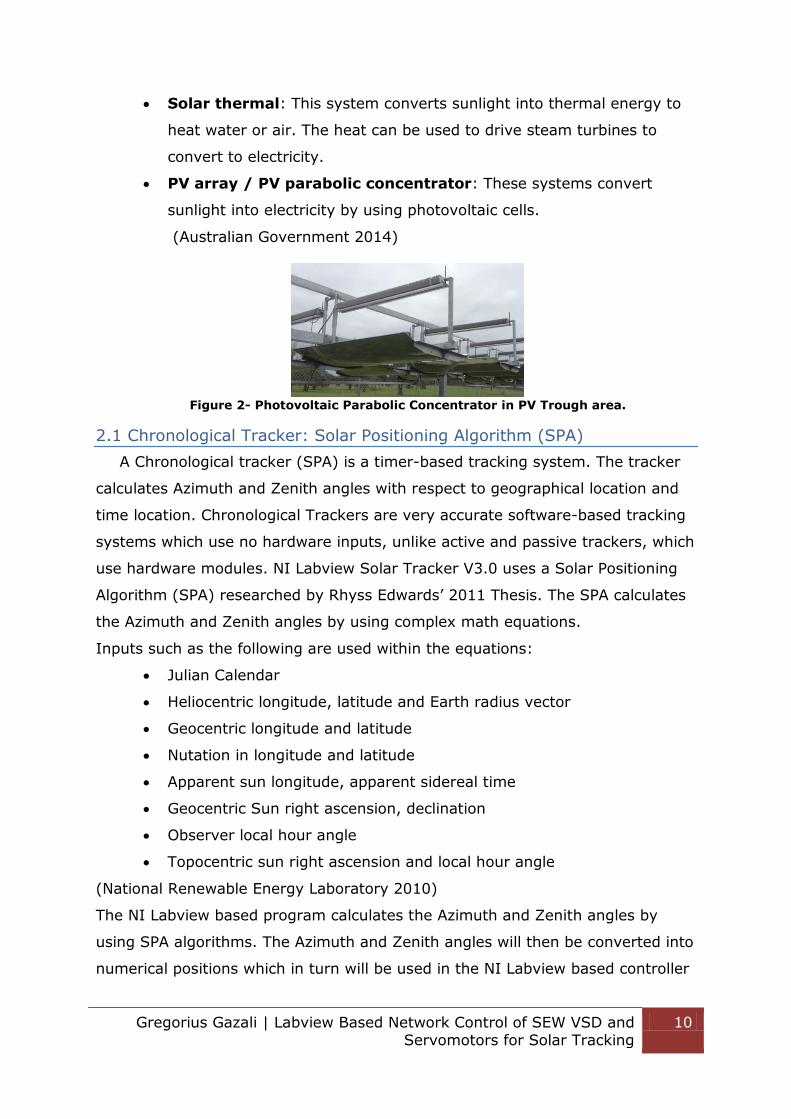
PV array / PV parabolic concentrator: These systems convert
sunlight into electricity by using photovoltaic cells.
(Australian Government 2014)
Figure 2- Photovoltaic Parabolic Concentrator in PV Trough area.
2.1 Chronological Tracker: Solar Positioning Algorithm (SPA)
A Chronological tracker (SPA) is a timer-based tracking system. The tracker
calculates Azimuth and Zenith angles with respect to geographical location and
time location. Chronological Trackers are very accurate software-based tracking
systems which use no hardware inputs, unlike active and passive trackers, which
use hardware modules. NI Labview Solar Tracker V3.0 uses a Solar Positioning
Algorithm (SPA) researched by Rhyss Edwards’ 2011 Thesis. The SPA calculates
the Azimuth and Zenith angles by using complex math equations.
Inputs such as the following are used within the equations:
Julian Calendar
Heliocentric longitude, latitude and Earth radius vector
Geocentric longitude and latitude
Nutation in longitude and latitude
Apparent sun longitude, apparent sidereal time
Geocentric Sun right ascension, declination
Observer local hour angle
Topocentric sun right ascension and local hour angle
(National Renewable Energy Laboratory 2010)
The NI Labview based program calculates the Azimuth and Zenith angles by
using SPA algorithms. The Azimuth and Zenith angles will then be converted into
numerical positions which in turn will be used in the NI Labview based controller

Gregorius Gazali | Labview Based Network Control of SEW VSD and Servomotors for Solar Tracking
11
to relocate the position of the Solar Energy modules directly-mounted to the
Solar Tracking System. (Edwards 2010)
An azimuth angle is measured in horizontal direction, clockwise from North.
Zenith angle is measured vertically down from the Up to the position of the sun
(See Figure 3).
Figure 3- Azimuth and Zenith angles
2.2 Small Solar Tracking System
The Direct Mount installation method has been proposed and agreed upon
for the “Small” Solar Tracking by Rhyss Edward in 2010. But in order to do so,
the Tilt MOVIDRIVE MDX61B servomotor has to be installed in an upside down
manner on the tilt beam. The motor will be attached directly to the pivot point of
the tilt beam. The current frames have been erected in the PV Trough area with
the roll beam attached to the SEW CFM71S synchronous servomotor. 3-phase
power cables are available through underground connections and cables for the
PV Concentrator array module can be attached to the roll beam.
Therefore some modifications are required in the future, such as:
Extending the pivot points to align with the shaft of the motor.
Creating a shaft that fit the MDX61B Servomotor and its gear box.
Mounting shaft & servomotor to the roll framework.
Installing tilt frames with DS56M motors.
Re-allocate the oil filter/breathers/drain plugs of the tilt motors.
(See Figure 4)
(Edwards 2010)
More information about the current Solar Tracking Condition please refers to
Appendix H.

Gregorius Gazali | Labview Based Network Control of SEW VSD and Servomotors for Solar Tracking
12
Figure 4- Final Model for the Small Solar Tracking System (Edwards 2010)
Figure 5- Current Roll Frame with SEW Motor attached in PV Trough Area
2.3 Installing a new SEW EURODRIVE MOVIDRIVE MDX61B
To operate a SEW MOVIDRIVE MDX61B using the IPOS Plus program, the
specification of the VSD needs to be upgraded from STANDARD to TECHNICAL.
SEW offers a free upgrade service for Murdoch University. User will need to
request the TAN Serial Number of the VSD via email to SEW. Please refer to
Appendix C for tutorials to install a new VSD for which IPOS is required.
3.0 Hardware: PC Master for Bench Test Solar Tracker
The current Windows 7 Master Computer is located in the Mechatronic room;
in the future NI MyRIO can be investigated as the Master (See Figure 6).
Figure 6- Window 7 Master Computer

Gregorius Gazali | Labview Based Network Control of SEW VSD and Servomotors for Solar Tracking
13
3.1 Bench Test Solar Tracker Equipment.
The Bench Test Solar Tracking System is a prototype system that is meant to
replicate the final tracking system. The bench test is used to develop and verify
the solar tracker V3.0 Labview Controller. The bench test consists of two
different SEW VSDs (MDX61B-0011 and MDX61B-0005), two DS56M
servomotors and two CFM71S servomotors. All of the equipment is verified for
the functionality of the Labview based control software. The current equipment
(See Figure 7) on the bench test is not up to standard for outdoor installation,
the equipment will need to be contained in a weather proof cabinet. SEW
equipment can be controlled via RS485 communication based two wires system,
therefore two stage communication conversion is used, the first stage is to
convert RS232 to RS485 four wires and second stage is to convert RS485 four
wires to RS485 based two wires system (See Figure 8). Converter is used to
communicate to the SEW MDX61B inverters, via XT port. XT port is a special
communication port available on SEW VSD (See Figure 10) See Chapter 4.1 for
more information about the project’s communication protocol.
Figure 7- Solar Tracker Bench Test

Gregorius Gazali | Labview Based Network Control of SEW VSD and Servomotors for Solar Tracking
14
Figure 8- Project Communication interconnections (See Chapter 4.1)
Figure 9 – SEW Eurodrive RS232 to
RS485 Converter
Figure 10 - XT Port
Figure 11- CFM71S motor at the bottom of Bench Test apparatus
Figure 11 above depicts the SEW CFM71S motor located at the bottom of the
bench test for investigation, more information about SEW equipment is provided
in Appendix L.
3.2 Manual Switches [X13 Port]
There are 12 switches (S) attached to both of the Drives, S1-6 for Drive 1
and S7-12 for Drive 2. The switches have been configured similarly on each of
the drives to avoid confusion.
S1 & S7 is used as a reference cam signal; it will stop the reference
mode operation and indicate IPOS system is referenced.
RS232 (DB9)
RS485 (DB9)
RS485 (Two-wires)

Gregorius Gazali | Labview Based Network Control of SEW VSD and Servomotors for Solar Tracking
15
S2&S8 is used to reset the MOVIDRIVE MDX61 during fault.
S3&S9 is used as a controller inhibit function, this switch have to be
activated to upload parameters to the drive or controlling the drive via
MOVITOOL Motion Studio, can be used as a Emergency Stop.
S4&S10 is used to enable the drive for operation, this is an interlock
for automatic, jog and reference mode. The mode will not be activated
unless this switch is active.
S5&S11 and S6&S12 are used as a hardware limit switch for Solar
tracking System. These limit switch will define the maximum travel
that the Solar Tracking System can achieve.
The Table 1 will explain the connections between the Hardware Switch and the VSD Port.
Switch Number Port Number Function
S1&S7 X13:4 Reference Cam
S2&S8 X13:3 Fault Reset
S3&S9 X13:1 Controller Inhibit
S4&S10 X13:2 Enable
S5&S11 X13:5 Lim Switch CW
S6&S12 X13:6 Lim Switch CCW Table 1- Hardware Switches located on Bench Test
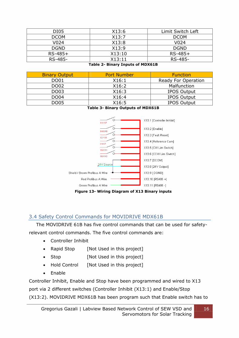
3.3 Binary inputs and outputs of MDX61B VSD
When X13:8 (VO24V) is in use, a jumper must be installed between X13:7
(DCOM) and X13:9 (DGND). The table 2 and 3 provide the function of each
binary inputs and outputs. Figure 12 displays the wiring diagram of the X13 port.
Binary Input Port Number Function
DI00 X13:1 Controller Inhibit
DI01 X13:2 Enable/Stop
DI02 X13:3 Fault Reset
DI03 X13:4 Reference Cam
DI04 X13:5 Limit Switch Right
Figure 12- Switches for Drive 1 & 2
Gregorius Gazali | Labview Based Network Control of SEW VSD and Servomotors for Solar Tracking
16
DI05 X13:6 Limit Switch Left
DCOM X13:7 DCOM
V024 X13:8 V024
DGND X13:9 DGND
RS-485+ X13:10 RS-485+
RS-485- X13:11 RS-485- Table 2- Binary Inputs of MDX61B
Binary Output Port Number Function
DO01 X16:1 Ready For Operation
DO02 X16:2 Malfunction
DO03 X16:3 IPOS Output
DO04 X16:4 IPOS Output
DO05 X16:5 IPOS Output Table 3- Binary Outputs of MDX61B
Figure 13- Wiring Diagram of X13 Binary inputs
3.4 Safety Control Commands for MOVIDRIVE MDX61B
The MOVIDRIVE 61B has five control commands that can be used for safety-
relevant control commands. The five control commands are:
Controller Inhibit
Rapid Stop [Not Used in this project]
Stop [Not Used in this project]
Hold Control [Not Used in this project]
Enable
Controller Inhibit, Enable and Stop have been programmed and wired to X13
port via 2 different switches (Controller Inhibit (X13:1) and Enable/Stop
(X13:2). MOVIDRIVE MDX61B has been program such that Enable switch has to

Gregorius Gazali | Labview Based Network Control of SEW VSD and Servomotors for Solar Tracking
17
be activated to control the drives, as soon as a higher-priority commands such
as Stop and Controller Inhibit activated the drive will be disabled. (SEW
EURODRIVE 2012)
3.5 24V LED Binary Output [X16 Port]
The 24V Light Emitting Diode (LED) Binary Outputs on the bench test
apparatus will feedback the status of each drive (See Table 4 and Figure 14).
The binary output ports are located on X16 port of the VSD. Please note that
X16 port are sourcing (24V) output with a ground connected to X16:6. (SEW
EURODRIVE 2000)
X16 Port Function
X16:3 Inverter Ready
X16:4 IPOS Referenced
X16:5 IPOS in Position
X16:6 Ground for X16 Table 4- X16 Binary Output Ports
Figure 14- 24V LED attached to inverter binary outputs
Figure 15- 24 V LED X16 port Binary Output wiring diagram
3.6 SEW DS56M Synchronous Servomotor
Two of the same type of SEW Synchronous Servomotor and Resolver units
are available on the bench test system. Both motors are a DS Type Synchronous
Servomotor with Hollow Shaft Helical- Worm and Foot and B5-flange mounted

Gregorius Gazali | Labview Based Network Control of SEW VSD and Servomotors for Solar Tracking
18
type Helical Gear Units. (SEW EURODRIVE 2008) Table 5, 6 and 7 provides more
detailed information about the DS56M motor.
Motor Type
Label of Both Motors SA67 R37 DS56M/TF/RH1M/KK
Table 5- SEW Motor Label Information
Label Entry Description
SA67 1st Gear Unit Type & Size
R37 2nd Gear Unit Type & Size
DS56M Motor Type
/TF Thermistor (PTC resistor)
/RH1M Resolver
/KK Terminal Box Table 6- Breakdowns of the Motor Label (SEW EURODRIVE 2008)
DS56M Synchronous
Servomotor
Symbol Values
Rated Speed nN 3000 [min-1]
Static Torque M0 1 [NM]
Standstill current I0 1.65 [A]
Dynamic Limit Torque Mdyn 3.8 [NM]
Max permitted motor current
IMAX 6.6 [A]
Mass Inertia of Motor Jmot 0.48 [10-4 kg m2]
Mass inertia of brake Motor Jbmot 0.83 [10-4 kg m2]
Weight of Motor mmot 2.8 [kg] Table 7- DS56M Synchronous Servomotor Specifications (SEW EURODRIVE, 2010)
The Figure 16 below shows the general structure of DFS synchronous
servomotors that are located on the Bench Test. The motor used in this project
comes with an inbuilt resolver unit.
Please refer to SEW MDX61B Operating Instructions manual for the figure. Figure 16- General Structure of DFS synchronous servomotor (SEW EURODRIVE 2008)
[Removed in electronic Version]
3.7 DS56M Motor Gear Types
Table 8 explains the gear units attached to the DS56M synchronous
servomotors.
Gear Gear Unit Type Gear Unit Size
1st Gear Hollow Shaft Helical-Worm Gear 67
2nd Gear Foot and B5-flange mounted type Helical Gear
37
Table 8- Synchronous Servomotor Gears attached to Bench Test (SEW EURODRIVE, 2010)

Gregorius Gazali | Labview Based Network Control of SEW VSD and Servomotors for Solar Tracking
19
3.8 SEW CFM71S Synchronous Servomotor
The CFM71S motors are installed on the Roll shaft of the small solar tracking
system. CFM71S is a bigger and more powerful motor compared to the DS56M.
CFM71S motor should be driven by MDX61B0011-5A3-4-00 as it provides
greater current compared to the MDX61B0005-5A3-4-00 version. The Tables 9,
10 and 11 below provides more detailed information about the CFM71S motor
(See Figure 17).
Motor Type
Label of Both Motors SA77 CFM71S/TF/RH1M/SM50
Table 9- Label of Bigger SEW motor attached to Roll frame.
Label Entry Description
SA77 1st Gear Unit Type & Size
CFM71S Motor Type
/TF Thermistor (PTC resistor)
/RH1M Resolver
/SM50 Plug Table 10- Breakdowns of the Roll Motor Label
DS56M Synchronous Servomotor
Symbol Values
Rated Speed nN 3000 [min-1]
Static Torque M0 5 [NM]
Standstill current I0 3.3 [A]
Dynamic Limit Torque Mdyn 16.5 [NM]
Max permitted motor
current
IMAX 13.2 [A]
Mass Inertia of Motor Jmot 4.99 [10-4 kg m2]
Mass inertia of brake Motor Jbmot 6.72 [10-4 kg m2]
Weight of Motor mmot 9.5 [kg] Table 11- CFM71S Synchronous Servomotor Technical Information (SEW EURODRIVE
2010)

Gregorius Gazali | Labview Based Network Control of SEW VSD and Servomotors for Solar Tracking
20
Figure 17- CFM71S SEW Synchronous Servomotor
3.9 Encoders: Resolver RH1M Type
Both of the Motors have in-built encoder that uses a two pole Resolver Type
Encoder system provided by SEW. Murdoch University have purchased an
additional DER11B card which is used to communicate between the Resolver and
VSD. The DER11B card is essential for the IPOS Plus program. Detailed
information about RH1M resolver is provided in Table 12.
Max Speed Max
Frequency
Current
Output
Max Current Max Voltage
3000 rpm 150 Hz 1.65 A 6.6 A 400 V Table 12 - SEW Resolver Ratings
3.91 Optional Card X14: External Encoder and X15: Resolver Input
DER11B optional card allows communication between the VSD and Resolver
unit (See Figure 19). DER11B comes with two connection ports X14 (External
Encoder) and X15 (Resolver Input). SEW Resolver units are attached at each
end of the motor shaft. Two cables (See Figure 20) are connected to the
Resolver unit, one of the cable is a DB9 communications cable that is attached to
SEW MOVIDRIVE MDX61B X15 ports and the other cable is attached to a three
phase power line that is attached to X2 port of the VSD. (See Figure 18&19)
Figure 18- X2 Port of MOVIDRIVE
MDX61B
Figure 19- X14 and X15 Port of
MOVIDRIVE MDX61B

Gregorius Gazali | Labview Based Network Control of SEW VSD and Servomotors for Solar Tracking
21
Figure 20- SEW Resolver Connection
3.92 SEW Resolver: RH1M
Both CFM71S and DS56M SEW motors use RH1M resolver units (See Figure 22)
for speed and positional control. These Resolvers can determine the absolute
position of the motor shaft by using a rotor coil and two stator windings that
have an offset of 90˚ in relation to one another (See Figure 21). It uses the
concept of a rotary transformer, whereby the resolver has a single auxiliary
winding each in stator and the rotor (e.g. VR and V2) in order to transfer supply
voltage to the rotor without brushes. Both of the rotor windings are electrically
connected. (SEW EURODRIVE 1999)
Please refer to Page 12 of SEW Encoder System Manual for the figure Figure 21- Schematic diagram of RH1M resolver (SEW EURODRIVE 1999)
Please refer to Page 12 of SEW Encoder System Manual for the figure. Figure 22- SEW RH1M Resolver (SEW EURODRIVE 1999) [Removed in electronic Version]
Encoder Type RH1M
Supply Voltage 7 V/ 7 kHz
Max Current Consumption 70 mA
Number of Poles 2
Ratio 0.5
Output Impedance 200 … 330 Ω
Operating Temperature -55 …+125 ˚C Table 13- RH1M Encoder Specifications (SEW EURODRIVE 1999)
3.93 Signal Output of the resolver
Two different signals (V1 & V2) of varying magnitudes are induced in the
stator windings depending on the rotor position. V1 and V2 are modulated by
the supply voltage through induction. Each of the voltages induced on the stator
windings have sinusoidal characteristics. Both of the sinusoidal signals are offset
by 90˚ and evaluated in the inverter for zero passage (accumulator) and
amplitude (speed of motor). This will enable the resolver and inverter to obtain

Gregorius Gazali | Labview Based Network Control of SEW VSD and Servomotors for Solar Tracking
22
the information of rotor position, rotor speed and direction of rotation of the
rotor. (SEW EURODRIVE 1999)
Please refer to Page 12 of SEW Encoder System Manual for the figure Figure 23- Output voltages V1 and V2 of the resolver (SEW EURODRIVE 1999) [Removed in
electronic Version]
3.94 Resolver Connection Diagram
Resolver cables have been fabricated according to Figure 24 and Figure 25.
There was a major discrepancy between the diagram and the 12 pin connector
that was bought separately and not from SEW. The 12 pin connector that the
university bought has the numbering starting clockwise, while the diagram starts
the numbering anti-clockwise. Please refer to Appendix H for descriptive
information about the resolver wiring colours and functions.
Figure 24- Resolver Connection Diagram for RH1M type (SEW Eurodrive 2010)
12-Pin RS 12-Pin SEW Cable Colour DB-9 Pin no
Function
8 1 Orange 3 Reference +
7 2 Orange Stripes 8 Reference -
6 3 Blue 2 Cosine +
5 4 Blue Stripes 7 Cosine -
4 5 Green 1 Sine +
3 6 Green Stripes 6 Sine -
9 9 Brown 9 TF/KTY +
12 10 Brown Stripes 5 TF/KTY - Figure 25-12 Pin to DB 9-MALE Cable conversion for CFM71S Resolver unit
3.10 SEW VSD MDX61B-5A3: 0005/0011 unit structure
Figure 26 is the unit structure for both MDX61B VSD versions. Table 15 explains each of the module functions and whether the module is being used for
the project.
Please refer to Page 16 of MOVIDRIVE MDX61B Operating Instructions
Manual for the figure. Figure 26- Unit Structure of MDX61B-5A3 (SEW Eurodrive 2010) [Removed in electronic
Version]

Gregorius Gazali | Labview Based Network Control of SEW VSD and Servomotors for Solar Tracking
23
Number Currently Used? Functions
3 Yes X1 : Power Supply Connection
4 No MDX61B Fieldbus Port
5 Yes MDX61B Encoder Slot
6 Yes Shield Clamp for Signal Cables
7 No X10: Signal terminal strip for Binary Outputs
8 Yes X16: Signal terminal strip for Binary inputs and outputs
9 Yes X13: Signal terminal strip for binary inputs and RS-485
10 No X11: Signal terminal strip for Set point input AI1 and 10V
11 No X12: Sbus signal terminal strip
12 No (Factory Settings)
DIP Switches S11…S14
13 No XT: Slot for DBG60B Keypad or UWS21B serial
interface
14 Yes 7-Segment display
15 Yes Memory Card
16 No Grounding Screw
17 No X17: Signal terminal strip for safety contacts for
safe stop
18 Yes X2: Motor connection U,V,W, and PE connection
19 No X3: Braking resistor connection +R/-R and PE connection
20 Yes Power Shield clamp for motor and braking resistor Table 14- MDX61B module information (SEW Eurodrive 2010)
3.9 MOVIDRIVE Operating 7 Segment Display
Figure 27 explains the operating conditions for the MOVIDRIVE MDX61B 7-
Segment Display during operation. The 7-segment on each drive does not
display its address, however MOVITOOL MotionStudio software can be used to
change the address of the inverters.
Please refer to Page 142 of MOVIDRIVE MDX61B Operating Instructions
Manual for the figure. Figure 27- MOVIDRIVE MDX61B 7 Segment Display (SEW EURODRIVE 2010)
3.10 Circuit Protection for MOVIDRIVE MDX61B-5A3:0005/0011
Circuit protections exist for the two different MOVIDRIVE systems that are
currently set up in Bench Test Solar Tracker. Detailed information about the
circuit protection is listed in Table 15.

Gregorius Gazali | Labview Based Network Control of SEW VSD and Servomotors for Solar Tracking
24
Parameters Nominal Values
Max Short Circuit Current AC 5000 A
Max Supply Voltage AC 500 V
Max Fuse Rating AC 15 A/ 600 V
Suitable Ambient Temperature 40 ˚C
Max Ambient temperature 60 ˚C Table 15- Branch Circuit Protection for MOVIDRIVE MDX61B-5A3:0005/0011 (SEW
Eurodrive 2010)
3.11 MOVIDRIVE MDX16B VSD specifications
Table 16, 17, and 18 provides information about the specifications of the
different types of MDX61B VSD. Version 0005 is suitable for the DS56M motor
and 0011 is suitable for CFM71S motor due to the nature of the VSD outputs.
Configuration Position
Address Signature Axis type
Left 1 Drive1 MDX61B0005-5A3-4-00
Right 2 Drive2 MDX61B0011-5A3-4-00
Table 16- VSD Information from Movitools-MotionStudio
Drive Input Voltage Input Frequency Input Current
Drive 1 3Phase 380-500 V 50-60 Hz 1.8A AC
Drive 2 3Phase 380-500 V 50-60 Hz 2.8A AC Table 17- Supply Input for Each SEW VSD (Sibson 2012)
Drive Apparent Output Power
Rated Output Current
Output Frequency Range
Drive 1 1.4 kVA 2A AC 0-180 Hz
Drive 2 2.1 kVA 3.1A AC 0-600 Hz Table 18- Power Output for Each SEW VSD (Sibson 2012)
4.0 MOVILINK Communication Protocol: RS485
SEW uses MOVILINK propriety communication protocol to communicate
between equipment. MOVILINK supports communication via Two-Wire RS-485
on a single pair of cable and a ground cable. RS-485 communication networks
allow up to 32 devices to communicate at half-duplex. The maximum distance
for this communication is 1200 meters. (B&B Electronics 2014)

Gregorius Gazali | Labview Based Network Control of SEW VSD and Servomotors for Solar Tracking
25
4.01 Two-Wire RS-485
In two-wire mode, the transmitter and receiver of each device are connected
together. Communication is limited to Half-Duplex. MOVILINK is a master to
slave protocol; the slaves which are the VSDs in this context cannot
communicate directly with each other. All communication is initialised by the
master, which in this context is the PC. Two-wire have the advantage of lowering
wiring costs as it consist of two wires and a ground cable (B&B Electronics 2014)
4.1 RS485 to RS232 Terminal Block
The Windows 7 based PC master only supports RS-232 communication, but
the slave SEW MDX61B supports RS-485 communication. Therefore, NI USB-485
was used to convert RS-232 to RS-485 (See Figure 31). Since SEW MDX61B
VSD supports two-wire RS-485, terminal block was used to convert the four-wire
USB-485 DB9 to two-wire RS485 (See Figure 28). The external 120Ω resistor is
needed at the master side of the terminal block between the two wires, to
ensure correct termination of the packets, to ensure that the packets are
correctly sent and received by the Master and Slaves.
Figure 28 – PROFIBUS A to DB9 terminal block with resistor
Figure 29- Daisy Chained Slave
connections (Slave Side)
Connection of Purple RS-485 cable to Drive 1: The RS-485 connection is connected to X13:9, 10, 11 Slave 1 and Slave 2 ports
(Port 5 and 6, the first two USB ports located at the back of the PC). These ports
are dedicated for RS485 communication protocol ports.

Gregorius Gazali | Labview Based Network Control of SEW VSD and Servomotors for Solar Tracking
26
Figure 30- DB9 Female Type
terminal block
Figure 31- NI DB9 Male RS-485 to USB
Converter
Window 7 Master COM-PORT 5&6 are modified to RS-485 TWO-WIRE Auto
communication settings by the help of Will Sterling. Only COM-PORT 5&6 can be
used to communicate to MOVIDRIVE MDX61B. (See Figure 32)
Figure 32- NI RS-485 to USB converter COM-PORT 5&6
4.2 DB9 Pin Connector
RS-485 Two-Wire Half-Duplex communication only uses a twisted-pair
communication cable (RS-485+ and RS-485-) and a ground cable to reduce
noise . Only 5 pins (Pin 1, 4&8 and 5&9) of DB9 connector need to be connected
to the two-wire cable. In theory, the ground cable is not necessary (See Figure
32). Table 19 will provide detailed information about the four-wire RS485 DB9
pinout.
Pin Number Colour Abbreviation Function
1 Brown GND Common Ground
4 Yellow RXD+ Receive Data +
5 Green RXD- Receive Data -
8 White TXD - Transmitted Data +
9 Black TXD + Transmitted Data - Table 19- Male DB 9 Pin out
4.3 Two-wire cable pin-out
Table 20 explains the two-wire RS485 cable pin out.
Colour X13 Port Number Function
Red X13:10 RS-485+
Green X13:11 RS-485-
Shield X13:9 Shield or Ground Table 20- Two-wire cable Pin out

Gregorius Gazali | Labview Based Network Control of SEW VSD and Servomotors for Solar Tracking
27
4.4 Four-wire RS485 to two-wire RS485 pin out
Figure 33 and Table 21 explain the correct colour connection for each of the
cables. Please note Pin4-8 and Pin5-9 have to be connected together because
NI USB RS-485 converter is in four wire mode, while the Window 7 and
MOVIDRIVE MDX61B are in two-wire mode.
Figure 33- NI RS485-USB to PROFIBUS A connection (created using TinyCAD)
Two-wire Cable DB9 Cable Function
Red Yellow+White RS-485+ & RXD+
Green Green+Black RS-485- & RXD-
Shield Brown Shield/Ground Table 21- two-wire and DB9 Connections
4.5 Recommended Cable Specification:
The cables recommended by SEW EURODRIVE are cables that consist of 2-core twisted and shielded cable (See Table 22).
Specifications
Conductor Cross Section 0.5-0.75 mm2 (AWG20-18)
Cable Resistance 100-150 Ω at 1MHz
Capacitance per unit length ≤40 pF/m at 1kHz Table 22- Cable Properties (SEW EURODRIVE 2001)
5.0 Introduction to Movitools MotionStudio
MOVITOOLS MotionStudio is SEW EURODRIVE propriety software that
establishes communication and executes functions with SEW EURODRIVE units.
MOVITOOLS MotionStudio supports, Serial RS-485, Sbus, Ethernet, EtherCAT
and Fieldbus communications. However, the MOVIDRIVE MDX61B Murdoch
University purchased units can only communicate via RS485 or Sbus. In order to
communicate with an alternative method, an extra communication card can be

Gregorius Gazali | Labview Based Network Control of SEW VSD and Servomotors for Solar Tracking
28
purchased and attached to the current MOVIDRIVE MDX61B. In this project RS-
485 communications was used. MOVITOOLS software allows users to modify
parameter tree and execute start-up for new SEW VSD or SEW motors (SEW
EURODRIVE 2012). Chapter 5.1 will explain the telegram structure used to
communicate between the master and the slave.
5.1 Telegram Structure of MOVIDRIVE MDX61B
There are two important RS-485 telegram structures that SEW MOVIDRIVE
MDX61B uses to communicate from Master to Slave, Request Telegram and
Response Telegram. The Master will send the request telegram to each of the
drives and the slaves will reply with a Response telegram. Each of the structures
will start with an idle time of at least 3.44 milliseconds to clearly identify the
type of telegram, hence a new request telegram cannot be sent until
6.88miliseconds has elapsed. When word information (16-bit) is sent within the
user data, the high byte is sent first followed by the low byte. A wait time of 20
milliseconds has been implemented in the NI Labview Solar Tracker V3.0 to
ensure correct telegram transmissions. (SEW EURODRIVE 2001)
5.2Request Telegram Structure
The request telegram from the PC consists of 10 bytes packets, starts with
Start Delimiter 1 byte (SD1) hexadecimal number 02 for request telegram; the
Start Delimiter is unique, it specifies a request and not a response telegram. The
next byte is the address type byte (0-255), following with Protocol data unit
type, then the protocol data unit (PDU) and finally the Block Check Character
(BCC), this is shown in figure 34. (SEW EURODRIVE 2012)
Please refer to Page 18 of MOVIDRIVE Serial Communication manual for the
figure. Figure 34- Request Telegram Structure) (SEW EURODRIVE 2001)
5.3 Response Telegram Structure
The response structure starts with start delimiter 2 (SD2) hexadecimal
numbers 1D, followed by the slave address, PDU type, PDU and lastly the BCC.
This is shown in Figure 35.
Please refer to Page 18 of MOVIDRIVE Serial Communication manual for the
figure. Figure 35- Response Telegram Structure (SEW EURODRIVE 2001)

Gregorius Gazali | Labview Based Network Control of SEW VSD and Servomotors for Solar Tracking
29
5.4 Telegram: Individual Address Type
Each inverter can be addressed individually, with the address ranging from 0
to 99; the bench test system has the Tilt VSD as address 1 and the Roll VSD as
address 2.
5.5 Telegram: PDU Type
Bit 7 of the PDU Type (TYP) refers to cyclical or a-cyclical type of
transmission. For Cyclical transmission data, Bit 7 will be 0 and vice versa. The
cyclical data is type 05hex, it has 3 Process Data Words (See table 23). For type
05hex the PDU length will be 6 bytes and total telegram length will be 10 bytes.
A-cyclical transmission TYP 86hex can be also used to retrieve parameter values
from the inverters; meanwhile the a-cyclical contain 12 byte telegrams (See
Table 24). Both 05hex and 86hex TYP are used in NI Labview program. (SEW
EURODRIVE 2012)
Please refer to Page 23 of MOVIDRIVE Serial Communication manual for the
figure.
Figure 36- PDU Type Telegram (SEW EURODRIVE 2001)
TYP byte PDU Description Telegram length
05Hex 1Dec 3PD 3 process Data words 10 Table 23- PDU Types in Cyclical Transmission (SEW EURODRIVE 2001)
A-cyclical transmission will be used in NI Labview to request Binary inputs and
fault status. More information is provided in the later chapter. (See Chapter 12)
TYP byte PDU Description Telegram length
86Hex 134Dec PARAM+0PD 8 bytes parameter channel data, without process data.
12
Table 24- PDU Type in A-cyclical transmission (SEW EURODRIVE 2001)
5.6 Telegram: Block Check Character [BCC] and Parity
MOVILINK protocol transmission uses the combination of character parity and
block parity to achieve secure communication. Without a correct BCC, the SEW
VSD will ignore the telegram. Each byte of the 9 bytes is calculated in such a
way that, if the calculated BCC adds up to an odd number it will set HIGH/1 in
the calculated BCC. For example the first bit column adds up to five (vertically),

Gregorius Gazali | Labview Based Network Control of SEW VSD and Servomotors for Solar Tracking
30
odd number, therefore the BCC calculated will be flagged high/1. Following on to
the next column, the calculated hex is two, an even number; therefore the BCC
will be flagged low/0. The total calculated BCC will only depend on the Process
Data (8 bits). (See Figure 37)
Please refer to Page 25 of MOVIDRIVE Serial Communication manual for the figure.
Figure 37- MOVILINK -Creating BCC [Removed in electronic Version]
5.7 MOVILINK Protocol
SEW uses the MOVILINK communication protocol to communicate between
SEW equipment. Then MOVILINK protocol is supported by the RS-485 network
with the following specifications; 11 bits, then 1 start bit, 8 data bit, 1 parity bit
and 1 stop bit as shown in Figure 38. The Start bit is always a logical 0 and
parity is even. The protocol ends with 1 stop bit.
Please refer to Page 26 of MOVIDRIVE Serial Communication manual for the figure.
Figure 38- MOVILINK Character frame (SEW EURODRIVE 2001) [Removed in electronic
Version]
5.8 Telegram: Data contents and Process Data Unit (PDU)
The Parameter channel is used for a-cyclical telegram, during the request of
a-cyclical telegram the telegram must follow the structure as shown in Figure
39. The Structure of the MOVILINK parameter channel made up of;
A management byte
A reserve byte
An index word (High and Low bytes)
Four data bytes
Please refer to Page 24 of MOVIDRIVE Serial Communication manual for the figure.
Figure 39- MOVILINK Parameter channel structure (SEW EURODRIVE 2001) [Removed in
electronic Version]

Gregorius Gazali | Labview Based Network Control of SEW VSD and Servomotors for Solar Tracking
31
5.9 Byte 0 - Management
The management byte 0, as shown in figure 40 is used to provide important
service parameters such as the, Service Identifiers, Data Length, Version and
status of the service. Bit 0 to bit 3 of the management byte is used as the
service identifier type. Bit 6 of the Management byte is used as a handshake bit;
is used in cyclical transmission as an acknowledgement between controller and
VSD. The VSD uses Bit 6 to signal to the controller whether the service was
performed or not. At the same time Bit 7 of the Management byte is used as a
status bit for error detection during the service (See Figure 40). (SEW
EURODRIVE 2001)
Please refer to Page 29 of MOVIDRIVE Serial Communication manual for the
figure.
Figure 40- Byte 0 Management Structure (SEW EURODRIVE 2001) [Removed in electronic
Version]
For more information about the telegrams please refer to Appendix G -
MOVILINK telegram.
5.10 Process Output (PO) Data Descriptions
Process data descriptions define the data that is used in a request telegram
to the MOVIDRIVE MDX61B units. All three process data words PO1 [P870], PO2
[P871] and PO3 [P872] can be assigned individually by users. P870, P871 and
P872 are fieldbus parameter index. Process output data received by a
MOVIDRIVE will not be processed according to the new actual value until the
fieldbus parameter P876 (Enable PO data=ON) is reactivated by the request
telegram, reactivation of P876 have been implemented in NI Labview software.
(SEW EURODRIVE 2000)
Each of the process output data contains:
Low Control Word 1 [PO1] (Operation mode)
High Control Word 2
Speed Set-point [PO2] (Speed of the motor)
Current Set-point [PO3] (Position of the motor)
More information about PO will be discussed in Chapter 11.

Gregorius Gazali | Labview Based Network Control of SEW VSD and Servomotors for Solar Tracking
32
5.11Process Input (PI) Data Descriptions
Process input words (PI1, PI2 and PI3) are Actual Value of the motor. PI1,
PI2 and PI3 words are returned by the MOVIDRIVE inverter to PC Master
through response telegram. The PI can be used as a feedback data of the
current system (SEW EURODRIVE 2000). Every request telegram will be replied
with response telegram.
Each of the process input data contains:
Low Status Word 1 [PI1] (Status of the operation mode)
High Status Word 2
Speed Actual value [PI2] (Current speed of the motor)
Current Position [PI3] (Current position of the motor)
More information about PI will be discussed in Chapter 11.
5.12 Enable PO Data
For the request telegram, Enable Process Output Data is used to change the
set-point description parameters, Speed Set-point (PO2) and Current Set-point
(PO3). When requesting a new position, PO data are automatically disabled and
have to be reactivated by the Master PC in order to relocate the motor position
or alter the motor speed. This step is important for higher-automation control
such as controlling the inverters via NI Labview. This step has been implemented
in the Solar Tracking Controller V3.0 initialization stage. (SEW EURODRIVE
2012)
5.13 Control Word [PO1]
Following from Chapter 5.10, the request telegram Control word is 16 bits
long, but only the low 8 bits are used in this project to control Automatic, Jog
and Reference mode. Each of the low bits has a permanent factory setting
inverter function assigned to it. Only Bit 0, 1, 2 and 6 are used in this project.
The rest of the bit should be set to 0. During operation, bit 0, 1 and 2 has to be
enabled for the IPOS function. Detailed information about each bit of the control
word is provided in Table 25.

Gregorius Gazali | Labview Based Network Control of SEW VSD and Servomotors for Solar Tracking
33
Bit Function Description
0 Controller Inhibit 0= Enable 1= Inhibit controller,
activate brake
1 Enable/Rapid Stop 0=Rapid Stop
1=Enable
2 Enable/Stop 0=Stop with ramp
1= Enable
3 Hold Control 0=Not active
1=Active
4 Ramp Generator
Selection
0=Ramp 1
1=Ramp 2
5 Parameter Set 0=Parameter set 1
1=Parameter set 2
6 Reset 0=Not active
1=Reset fault
7 Reserved Reserved bits should be
set to zero. Table 25- Low Control [PO1] bits for MOVIDRIVE MDX61B (SEW EURODRIVE 2000)
5.14 Controller Inhibit Control Command
Controller Inhibit bit command allows the user to disable the power output of
the VSD. Since the system does not have mechanical braking, the servo motor
will coast to rest. Controller Inhibit is the highest priority command.
5.15 Enable Control Command
Enable bit allows the user to enable the drive inverter via the fieldbus system
(RS-485). In order for the Enable command to be activated, all three bits (bit 0,
1 and 2) have to be switched high. This step has been added in the Solar
Tracking Controller V3.0 Initialization stage. For more information regarding the
telegrams please refer to Appendix G.
5.16 Status Word [PI1]
From the response telegram the Status Word is 16 bits long but only low 8
bits are used to act as a feedback for the Solar Tracking program. Status bits are
used to feedback of the drive conditions. Detailed information about Low Status
word is provided in Table 26.

Gregorius Gazali | Labview Based Network Control of SEW VSD and Servomotors for Solar Tracking
34
Bit Status Description
0 Enable output stage 0=Output is Inhibited 1=Output is Enabled
1 Inverter ready for operation 0=Inverter not ready (fault) 1=Inverter ready
2 PO data enabled 0=PO data inhibited 1=PO data enabled
3 Ramp Generator settings 0=Ramp 1 1=Ramp 2
4 Active parameter set 0=Parameter 1 1=Parameter 2
5 Fault/Warning 0=No Fault/Warning 1=Fault / Warning
6 Limit Switch CW active 0= Not Active 1=Limit Switch CW Active
7 Limit Switch CCW active 0= Not Active 1=Limit Switch CCW Active
Table 26- Low Status Bits [PO1] for MOVIDRIVE MDX61B (SEW EURODRIVE 2000)
5.17 Read & Write Request
For reading a parameter from a VSD (See Figure 41), the Master has to carry
out a Read Request to the SEW MOVIDRIVE VSD. Either a Read Confirmation
(No Error) or Read-error confirmation will be returned to the Master. The
response telegram will contain the same byte length of the request telegram,
either 10 bytes for synchronous or 12 bytes for a-synchronous telegrams is used
in this project.
Please refer to MOVIDRIVE Fieldbus Unit Profile with Parameter List Manual Page 30 for the Figure.
Figure 41-Read Request (SEW EURODRIVE 2000)
6.0 Introduction to IPOS-Plus
IPOS-Plus is a positioning and sequence controller that allows a user to
choose exactly the types of position control as required in this project. IPOS-Plus
is SEW-EURODRIVE propriety software. IPOS-Plus is a closed loop system. IPOS-
Plus uses encoder or resolver feedback system to achieve point-to-point
positioning capability. The IPOS Bus Positioning application module is used in-
conjunction with the NI Labview program to accomplish the final Solar Tracking
System. (SEW EURODRIVE 2012)

Gregorius Gazali | Labview Based Network Control of SEW VSD and Servomotors for Solar Tracking
35
6.1 Programming with MOVITOOLS Motion Studio for IPOS-Plus
NI Labview will operate in conjunction with IPOS to create the Solar Tracking
System, NI Labview will calculate a new position for the motors and IPOS will
control the speed and position of the motors. IPOS-Plus processes a task
cyclically.
6.2 Parameter List for Programming Purposes
Complete parameter lists including HEX/DEC code are available in Chapter 7
of SEW Manual IPOS-Plus Positioning and Sequence Control System. These
parameters are important for understanding telegrams and very useful for
choosing parameters. (SEW EURODRIVE 2001)
6.3 Reference Mode
There are 9 reference types which can be used to configure the MOVIDRIVE
MDX61 VSD. They are:
0. Reference travel to zero pulse
1. CCW end of the reference cam [Currently used]
2. CW end of the reference cam
3. CW limit switch
4. CCW limit switch
5. No reference travel
6. Reference cam flush with CW limit switch
7. Reference cam flush with CCW limit switch
8. Without enable
Jarred Sibons 2012 has concluded that Reference Mode 1 is suitable for the Solar
Tracking System (Sibson 2012). Therefore NI Labview Solar Tracking V3.0 was
designed with Reference Mode 1. It is up to the next project to determine which
reference mode is suitable for the “small” tracking system, as the current mode
require a cam signal to reference the system. This means a limit switch will need
to be attached to either the mid-way or most east position (Sun cycle). Refer to
Appendix F for more information about the reference mode.

Gregorius Gazali | Labview Based Network Control of SEW VSD and Servomotors for Solar Tracking
36
6.4 Reference Mode 1: CCW end of the reference cam
In reference mode, the motor will rotate CCW until the reference cam signal
is pulsed on input X13:4. During the implementation of the system a reference
cam hardware limit switch should be placed either on the most east position or
the middle of the system. (SEW EURODRIVE 2012)
6.5 IPOS Parameters in MOVITOOL MotionStudio
MOVITOOL MotionStudio PC software can be used to modify MDX61B VSD
parameter tree. These are the following parameters that can be modified in the
software:
IPOS Reference Travel
IPOS Travel Parameters
IPOS Monitoring
IPOS Special Functions [will not be covered]
IPOS Encoder
Absolute encoder [will not be covered]
IPOS Modulo Function [will not be covered]
IPOS Synchronization [will not be covered]
6.6 IPOS Reference Travel
When Choosing the IPOS reference travel tab, the following parameters can
be modified as shown in Figure 42:
Reference Offset
Reference Speed 1
Reference Speed 2
Reference Travel Type
Reference travel to zero pulse
For Bench Testing the current reference speed is set to 600(1/s) and travelling
in the CCW direction (Reference Mode 1). However in the future, a trial and
error method of investigation will be needed to find the appropriate reference
speed that can be used to minimize reference error due to inertia in the system.

Gregorius Gazali | Labview Based Network Control of SEW VSD and Servomotors for Solar Tracking
37
Figure 42- Current IPOS Reference Travel Parameters
6.7 IPOS Travel Parameters
When choosing the IPOS Travel Parameters tab, the following parameters can
be modified as shown in Figure 43:
Gain X-controller
Positioning Ramp
Travel Speed (CW&CCW)
Speed precontrol
Ramp type and mode
During the initial start-up wizard, these values have already been calculated by
the wizard, hence no modifications are needed.
Figure 43- IPOS Travel Parameters
6.8 IPOS Monitoring
When choosing the IPOS Monitoring tab, the following parameters can be
modified as shown in Figure 44:
Software Limit Switch (Left & Right)
Position Window (Factory Setting)
Lag Error Window (Factory Setting)
A software limit switch can be modified, however the position window and lag
error window should left as the factory settings. A software limit is also available

Gregorius Gazali | Labview Based Network Control of SEW VSD and Servomotors for Solar Tracking
38
in NI Labview Solar Tracker Controller V3.0, it is recommended to use this
Labview software limit switch as it is easier to modify.
Figure 44- IPOS Monitoring Parameters
6.9 IPOS Encoder
When choosing the IPOS Encoder tab, the following parameters can be
modified as shown in Figure 45:
Source actual position
Encoder Scaling Factor
Encoder Counting Direction
Users will not need to modify any of the IPOS Encoder parameters since the only
Encoder attached to the motor is a SEW Resolver unit. The only time an operator
will need to modify IPOS Encoder parameters, is when a future project holder
would like to investigate the use of external encoders.
Figure 45- IPOS Encoder Parameters
7.0 MOVITOOL MotionStudio: IPOS Plus Positioning via Bus
Robust testing has confirmed that the Window 7 is capable to run the
MOVITOOL MotionStudio. The tutorial about the MOVITOOL software is attached
in the appendix. Tests have confirmed that the master PC is able to control the
inverters via:

Gregorius Gazali | Labview Based Network Control of SEW VSD and Servomotors for Solar Tracking
39
SEW RS232 to RS485 converter which is then attached to the
MOVIDRIVE MDX61B XT Port.
RS-485 two-wire automatic.
A second test has validated that MOVITOOL is capable of controlling both
versions of the VSD and both types of the synchronous servomotors under
manual mode. Manual operation such as controlling the speed of the rotor, the
direction of the rotor and tests of the functionality of the hardware limit switches
attached to the X13 port. (See Chapter 3.2)
A third test has validated the IPOS program within the MOVITOOL MotionStudio.
Robust testing of the IPOS Positioning and Sequence Control functionality were
held in the third stage of the test. Three IPOS modes were tested, Automatic,
Jog and Reference mode. The tests have confirmed the functionality of each of
the modes and helped to understand the different telegrams needed to control
each mode. More information has been provided in Appendix F.
7.1 Positioning via Bus modes
There are three modes that IPOS-Plus Positioning via Bus offers, Automatic,
Reference and Jog. These three modes are suitable for the Solar Tracking
System and hence IPOS-Plus Positioning via Bus can be used to control the
speed and position of the motors. NI Labview and MOVIDRIVE inverters will work
together to control the Solar Tracking System. Note the telegram sent from the
Master PC to Inverter Slave to activate IPOS-Plus Reference mode is similar to
the telegram that will be sent from NI Labview software to activate the reference
mode. Figure 46 shows the PC control windows during MOVITOOL Positioning Via
Bus.
Figure 46- Window XP Bus Positioning Monitor & Control Window

Gregorius Gazali | Labview Based Network Control of SEW VSD and Servomotors for Solar Tracking
40
7.2 IPOS Positioning via Bus: Reference Mode
Reference mode is an important feature in autonomous applications such as
the Solar Tracking System. Reference mode will ensure that the system will
always be accurate. In Reference Mode, the inverter will operate at a defined
Reference Mode and Reference Speed; these parameters can be modified in
IPOS Parameter Tree. (See Figure 47)
Figure 47- Window XP IPOS Reference Travel
7.3 IPOS Positioning via Bus: Automatic Mode
Automatic mode will be the main operation mode of Solar Tracking System.
The System will need to be referenced first before moving into Automatic mode.
In Automatic mode the inverter will move automatically at a specified Set-point
speed and Target Position. The position will be controlled by an in-built resolver
unit. (See Figure 48)
Figure 48- Window XP IPOS Automatic Mode

Gregorius Gazali | Labview Based Network Control of SEW VSD and Servomotors for Solar Tracking
41
7.4 IPOS Positioning via Bus: Jog Mode
Jog mode will be available in the Solar Tracking System; Jog mode can
manually control the position of the system by controlling the motor in CW or
CCW direction. Only Set-point speed will need to be provided. (See Figure 49)
Figure 49- Window XP IPOS Jog Mode
7.5 Connecting Two MOVIDRIVE MDX61B via MOVITOOL MotionStudio
Two or more MOVIDRIVE MDX61B inverters can be connected to the
MOVITOOL network. The inverters will need to be daisy-chained via the same
network cable. Each of the VSD will need to be individually assigned with a
unique address, however MOVITOOL MotionStudio unable to detect two drives
automatically, user will need to manually add the drive from the Project/Network
folder as shown in the Figure 50 and 51.
Figure 50-Two MOVIDRIVES Offline File
Users can drag down the OFFLINE file or add configured unit manually to the
Network. Once the OFFLINE file is loaded to the drive, users can switch the Drive
to ONLINE Mode. The network will now have two drives connected under the
Serial (COM-PORT5) connection. When the project is saved, the configuration is
easily reloaded at any time so that in the future, 2 drives will automatically
connect in the network tab (See Figure 51). More information is attached in
Appendix F.

Gregorius Gazali | Labview Based Network Control of SEW VSD and Servomotors for Solar Tracking
42
Figure 51- Two Drives connected to Serial (COM5)
7.6 Verifying operation two MOVIDRIVE MDX61B via single RS-485
network.
Tests have verified that two of the MOVIDRIVE MDX61B that is connected
to the same RS-485 network can be controlled via the MOVITOOL Software. The
test consists of operating one of the drives (Drive 1) in Manual Mode and the
other (Drive 2) in IPOS mode. This test has verified that both motors can be
controlled via the MOVITOOL software at the same time. Please note for the
IPOS mode Controller Inhibit has to be ON to download the parameters. After
downloading ensure to switch off the Controller Inhibit to activate the motor.
7.7 Conclusion: MOVITOOL MotionStudio Software.
MOVITOOL MotionStudio can control the operation of MOVIDRIVE MDX61B
manually by operator interactions, but the objective of the Solar Tracking
System is to create a system that can track the position of the sun and relocate
the position of the Tilt and Roll motors autonomously. NI Labview software will
be used to achieve the outcome.
8.0 National Instrument Labview Programming Software
National Instrument Labview or NI Labview is graphical programming
software development environment that Murdoch University ICSE & ICE
Students have been studying since 2nd year of Engineering. It is ideal for
measurement and control system applications such as the Solar Tracking
System. NI Labview can also be used to change any parameters within the
inverter by sending a-cyclical telegrams (See Chapter 12). MOVITOOL can also
be used to change VSD parameters by sending the appropriate a-cyclical
telegram.

Gregorius Gazali | Labview Based Network Control of SEW VSD and Servomotors for Solar Tracking
43
8.1 List of Students contributed to Solar Tracking NI Labview Program
Following are the lists of students that have contributed to the Solar Tracking
NI Labview programs and their work were continued in this Project:
Previous ENG 454 Students prior to 2010
Rhyss Edwards S2 2010 Thesis
Jarrad Sibson S2 2012 Thesis
8.2 Project Objective for NI Labview
The Objective of NI Labview is to established communication and control of
the MOVIDRIVE MDX61B inverters via Serial RS-485. The previous students
have developed some codes known as the Solar Tracker V2.0. The program was
able to establish communication with the drives and request telegrams.
However, Solar Tracker V2.0 was incomplete and represented an early stage of
the entire project. Although that the communication had been established, there
was little error checking and robustness in the communication, the chronological
tracker has not been verified, little error with the request telegrams, incorrect
BCC error byte and there were scaling issues between NI Labview and
MOVITOOL results.
8.3 Window 7 Port validation via NI MAX
National Instrument Measurement & Automation Explorer (NI MAX) can be used
to view devices and instruments connected to a Windows 7 system. Users can
use NI MAX to verify the serial RS-485 connection to the MOVIDRIVE MDX61B.
Refer to Figure 52 for setting up the communication port. The port should be set
up as 9600 baud, 8 data bits, 1 stop bits, even parity, no flow control and 2 Wire
Auto transmission modes.

Gregorius Gazali | Labview Based Network Control of SEW VSD and Servomotors for Solar Tracking
44
Figure 52- NI MAX RS-485 to USB converter
9.0 Solar Tracker V2.0: Investigating problems
As previously explained, the solar tracking V2.0 was in an early stage of
development. It was able to extract information, motor position and binary
outputs, but unable to control the VSD. The hypothesis to the problem is that
there were incomplete or incorrect telegrams being sent to the VSD, as MDX61B
VSD will not respond to incorrect telegrams. During Labview operations,
Controller Inhibit switch has to be OFF and the servomotor has to be initialised
first by running IPOS Bus Positioning in reference mode.
To confirm the hypothesis, an extra NI USB-RS485 was attached to COMPORT 6,
with the intent to listen to the communication telegrams between master PC and
slave MOVIDRIVE with MOVITOOL, because MOVITOOL are able to control the
VSD successfully. Figure 53 shows the daisy chain connection with the extra RS-
485 cable to the COMPORT 5 cables and “Serial Read.vi” was used to read the
telegrams. Figure 53 and Table 27 describes the pin out of the extra
communication line connected to the terminal box.
Figure 53- COMPORT-6 and COMPORT-5 NI RS485-USB

Gregorius Gazali | Labview Based Network Control of SEW VSD and Servomotors for Solar Tracking
45
Pin Number Colour Abbreviation Function
1 Blue GND Common Ground
4 White RXD+ Receive Data +
5 Black RXD- Receive Data -
8 Yellow TXD - Transmitted Data +
9 Red TXD + Transmitted Data - Table 27- COMPORT6 Pin out
During the verification test, request telegrams from Table 29 are sent to the
VSD. Table 28 is the example telegram structure to control address 1 VSD in
automatic mode, with set-point speed of 1000 and target position of 1000.
SD ADR TYP PA1 PA1 PA2 PA2 PA3 PA3 BCC
Request 02 01 05 19 06 03 E8 00 00 F2
Response 1D 01 05 0A 1E 00 00 03 E8 E6 Table 28- MOVITOOL Telegram Request & Respond in hexadecimal
From analysing the communication telegrams between the master and slave via
Labview “Serial Read.vi”, MOVITOOL constantly send a-cyclical request
telegrams to the MOVIDRIVE in the background. As shown in Figure 54, the
yellow highlighted telegram is an example of synchronous telegram that user
requests and receives through IPOS Bus Positioning MOVITOOL via SEND PA
button. The green highlighted telegrams are the a-cyclical request telegram that
constantly executed by MOVITOOL. Telegrams that start with 02hex are request
telegram from Master PC and telegrams start with 01hex are response telegrams
from the VSD.
Figure 54- Telegram Read from NI Labview "Serial Read.vi"

Gregorius Gazali | Labview Based Network Control of SEW VSD and Servomotors for Solar Tracking
46
Further investigations of the Solar Tracker V2.0, found that the send request
telegram was incomplete; it was found that the BBC byte (10th byte) was
incorrectly implemented. Therefore, a correct BCC Checker and generator
(CompleteTelegram.vi) has been added to the Solar Tracker V3.0. Figure 55
depicts the CompleteTelegram.vi codes that concatenate the correct bcc to the
request telegram.
Figure 55- CompleteTelegram.vi
Figure 56 illustrate the correct calculated BCC byte produced by the Figure 55
code. Figure 56 BCC Byte need to be appended to the 10th byte of the request
telegram. The figure 56 shows the same BCC byte as Table 28, F2 request
telegram. This verifies the functionality of the (CompleteTelegram.vi).
Figure 56- CalcBCC.vi (Correct BCC value)
9.1 Conclusion: Solar Tracker V2.0
The hypothesis about incorrect request telegrams was correct; the original
request telegram was incomplete and hence the VSD will not execute the
request telegrams. Correct BCC has been added to the new Solar Tracker V3.0.
The program calculates the BCC needed to complete the telegram and append

Gregorius Gazali | Labview Based Network Control of SEW VSD and Servomotors for Solar Tracking
47
the BCC to the 10th byte of the request telegram. A-synchronous telegram has
been added in the “Do nothing” stage to study more about the a-synchronous
telegrams. It will request parameters such as current speed, current position,
binary inputs, fault status and process data for debugging purposes. More
information about telegrams is provided in Appendix G.
9.2 NI Labview and IPOS Operating Modes
Three modes can be used by NI Labview for SEW VSD IPOS Plus Bus
Positioning as the following;
1. Automatic - in Automatic mode the MOVIDRIVE will autonomously
control the movement of the motor until the Target Distance has been
achieved. Target Distance and Set-point speed need to be specified.
2. Reference - Reference mode will be executed depending on the
uploaded reference mode stored in MOVIDRIVE MDX61B parameter
tree. Currently both drives have reference mode 1 (CCW end of the
reference cam).
3. Jog - In Jog mode the MOVIDRIVE can control the motor CW or CCW
at a specified target speed until another telegram specify to stop the
service. Only Set-point speed needs to be specified.
MOVIDRIVE Mode
PO1 (Control Word)
PO2 (Set-point Speed)
PO3 (Target Position)
Automatic 1906 03E8 03E8
Reference 1106 03E8 1388
Jog 0B06 03E8 0000 Table 29- IPOS Modes PDU Telegram Structure [Hex Format]
Table 29 are the PDU request telegrams for the VSD. PO1 is used for Control
Word, PO2 is used for Set-point Speed and PO3 is used for Target Positon. Each
of the Process Output is 16 byte, 8 byte high and 8 byte low. NI Labview
program codes will be developed with the same PDU telegram structure as Table
29.

Gregorius Gazali | Labview Based Network Control of SEW VSD and Servomotors for Solar Tracking
48
9.3 Background A-cyclical Request telegram
The background a-cyclical telegrams are TYP 86 and have a management
byte of 31. The objective of the a-cyclical telegrams is to read data parameters
from the VSD, hence the 31hex Management Byte. TYP 86 is an A-cyclical
transmission that consists of a 8 bytes parameter channel without process data
and the telegram length is 12 bytes as explained in Chapter 5.14. The telegram
repeats itself with different index parameter. For example from the table below
the PA2 cycles from 210B, 210C, 210A and lastly 208E (See Table 29). Table 30
illustrates the function for each parameter.
Legends for Table 30:
M - Management Byte
R - Reserved Byte
IH - Index High Byte
IL - Index Low Byte
DA MSB - Data Most Significant Byte
DA - Data
DA LSB - Data Least Significant Byte
As explained, the 31hex of the management byte stands for a read service, while
32hex of the management byte stands for write service.
SD ADR TYP M R I H
I L
Da MS
B
Da Da Da LS
B
BCC
Request
(1)
02 01 86 31 00 21 0B 00 00 00 00 9E
Response
(1)
1D 01 86 31 00 21 0B 00 00 FF F9 87
Request
(2)
02 01 86 31 00 21 0C
`
00 00 00 00 99
Response
(2)
1D 01 86 31 00 21 0C 00 00 03 E8 6d
Request
(3)
02 01 86 31 00 21 0A 00 00 00 00 9F
Response
(3)
1D 01 86 31 00 21 0A 00 00 0A 17 PD
Request
(4)
02 01 86 31 00 20 8E 00 00 00 00 1A
Response (4)
1D 01 86 31 00 20 8E 00 00 00 3F 3A

Gregorius Gazali | Labview Based Network Control of SEW VSD and Servomotors for Solar Tracking
49
Table 30- A-cyclical background request telegrams
Index Number
Decimal Description
210B 8459 PI2 Actual Value
210C 8460 PI3 Actual Value
210A 8458 PI1 Actual Value
2107 8455 PO1 Set Point
2108 8456 PO2 Set Point
2109 8457 PO3 Set Point
Binary Inputs
208E 8334 Binary Input DI00-DI05
208F 8335 Binary Input DI01
2090 8336 Binary Input DI02
2091 8337 Binary Input DI03
2092 8338 Binary Input DI04
2093 8339 Binary Input DI05
Binary Outputs
209D 8349 Binary Output DB00-DO2
209E 8350 Binary Output DO01
209F 8351 Binary Output DO02
Other Useful Parameters Units Conversion index
2076 8310 Fault Status 0 0
207E 8318 Speed 1/s 66
2080 8320 Actual Position Inc 0 Table 31- Index parameters read from A-cyclical read
10.0 Bench Test 1: MOVIDRIVE Control with “Serial Write.vi”
Before moving on to the complex Labview program that has been partially
completed by previous students, a series of tests were carried out to figure out
the correct method to control the MOVIDRIVE via NI Labview VI, “Serial
Write.vi” was used to test the telegrams. The objective of the tests was to
figure out the current stage of the Solar Tracker V2.0 and to ensure the
synchronous request telegrams are correct. Table 32 depicts the different stages
used to investigate Solar Tracking V2.0 current stage and will be used for the
project plan.
Test Number Test Description Results
1 Writing 10 byte of request telegram to
drive 1 using Serial Write.vi
Unsuccessful
2 Writing 10 byte of request telegram to
drive 2 using Serial Write.vi
Unsuccessful

Gregorius Gazali | Labview Based Network Control of SEW VSD and Servomotors for Solar Tracking
50
3 Test No 1&2 + Sniffer program that
reads the telegrams sent and compare to MOVITOOL MotionStudio
telegrams.
Unsuccessful, the
telegrams sent by both NI Labview and
MOVITOOL are the same.
4 Open up IPOS Bus Positioning from MOVITOOL and control the
MOVIDRIVE in Automatic mode and leave the Bus Positioning window
open. Execute Test No 1&2.
Success, able to control both MOVIDRIVE by
alternatively using a single request telegram.
5 Redo Test No 4, with different telegrams to ensure that all modes
are working correctly
Success
Table 32- Bench Test: MOVIDRIVE Control with Serial Write.vi
Table 33 and 34 contains important telegrams that are used to control the VSD
operation. More information about each request will be explained in the Chapter 10.01.
SD ADR TYP PA1 PA1 PA2 PA2 PA3 PA3 BCC
Request (A1)
02 01 05 19 06 03 E8 03 E8 19
Request (A2)
02 01 05 19 06 03 E8 00 00 F2
Request (A3)
02 02 05 19 06 03 E8 03 E8 1A
Request (A4)
02 02 05 19 06 03 E8 00 00 F1
Request (R1)
02 01 05 11 06 00 00 00 00 11
Request (R2)
02 02 05 11 06 00 00 00 00 12
Request (J1+)
02 01 05 0B 06 03 E8 00 00 E0
Request (J2+)
02 02 05 0B 06 03 E8 00 00 E3
Request
(J3-)
02 01 05 0D 06 03 E8 00 00 E6
Request
(J4-)
02 02 05 0D 06 03 E8 00 00 E5
Table 33- Set of Telegrams for Bench Test
SD ADR TYP PA1 PA1 PA2 PA2 PA3 PA3 BCC
Stop 1 02 01 05 00 00 00 00 00 00 06
Stop 2 02 02 05 00 00 00 00 00 00 05 Table 34- Stop telegram for IPOS Bus Positioning operation

Gregorius Gazali | Labview Based Network Control of SEW VSD and Servomotors for Solar Tracking
51
10.01 Request (A1 & A2)
Request (Test1&2) telegrams in table 32 are used to control the drive in
automatic mode (CW direction depending on the initial position) to target
position 1000 (integer) with a set-point speed of 1000 (1/s). The only difference
between Test1&Test 2 is that the ADR byte, whereby Test1 is specifically for
Drive 1 and Test 2 is specifically for drive 2.
10.02 Request (A3 & A4)
Request (Test3&4) telegrams in table 32 are used to control the drive in
automatic mode (CCW direction depending on the initial position) to target
position 0 (integer) with a set-point speed of 1000 (1/s). Test 1 is for Drive 3
and Test 4 is for drive.
10.03 Request (R1 & R2)
Request (R1&2) telegrams in table 32 are used to control drive 1 and drive 2
in reference mode. After sending the telegram, the inverter will enter the
reference mode and the Reference Cam signal (X13:4) needs to be pulsed to
stop the Reference IPOS program. The reference mode telegram does not need
set-point speed and target position as the IPOS program will constantly run the
program until the reference cam signal is pulsed or a software/ hardware limit
have been reached or sent a telegram that consists of the 0000 control word.
10.04 Request (J1+ & J2+)
Request (J1+ and J2+) telegrams in table 32 are used to control the drive 1
and drive 2 in Jog mode CW direction at 1000 (1/s) set-point speed. The
telegrams does not need a target position, because the IPOS Jog mode will
continuously run at the set-point speed until another telegram is sent that
consist of the 0000 control word or software limit switch or hardware limit switch
is activated.
10.05 Request (J1- & J2-)
Request (J1- and J2-) telegrams in table 32 are similar to the previous (J1+
and J2+) request telegrams, but instead these telegrams will control drive 1 and
drive 2 in Jog mode CCW direction at 1000 (1/s) set-point speed.

Gregorius Gazali | Labview Based Network Control of SEW VSD and Servomotors for Solar Tracking
52
10.06 Stop Telegram
The stop telegram in table 33 can be used to stop any IPOS mode programs
that are currently running on each of the drives. The user will need to send the
telegram to the specified inverter. Stop 1 is for drive 1 and stop 2 is for drive 2.
10.1 Conclusion: Writing telegrams to MOVIDRIVE MDX61B
From Table 31 investigations, NI Labview software can be used to control
MOVIDRIVE MDX61B inverters but in order to do so, MOVITOOL MotionStudio
IPOS Bus Positioning window has to be running in the background to enable the
IPOS mode, which is not suitable. From the previous investigations, it comes to
assumption that the MOVITOOL software has to initialize a series of telegrams
prior to controlling each of the VSDs.
11.0 Bench Test 2: Analysing telegrams during IPOS Bus
Positioning monitor to control mode.
Following on from Chapter 10.1 assumption that the VSD need to be
initialized with a set of telegrams, it can be concluded that MOVITOOL sends a
set of telegrams to acknowledge both of the VSD, be controlled by RS-485. Test
2 is designed to study the behaviour of the MOVITOOL program during the
initialization stage. Table 35 depicts the two procedures that are needed for
control switchover; telegrams were recorded and investigated.
Step Number Description
1 Controller Inhibit have to be activated in order to
switch to control mode from monitor.
2 Controller Inhibit switch have to be deactivated
to execute service or telegrams, once in control mode.
Table 35- Two Step Process to switch over to Control mode from Monitor in MOVITOOL
Different a-cyclical telegram bytes were sent through the RS-485 serial line.
Instead of a management byte of 31 (read byte), MOVITOOL sends 3 different
management byte 32 (write byte) telegrams to the drive as soon as the Monitor
mode were switched to control mode. Figure 57 shows these control telegrams
and are highlighted in yellow.

Gregorius Gazali | Labview Based Network Control of SEW VSD and Servomotors for Solar Tracking
53
Figure 57- Example telegrams exchange between Master and Slave during Monitor to
Control mode switchover
SD ADR TYP M R I H
I L
Da MS
B
Da Da Da LS
B
BCC
Request
(1)
02 02 86 32 00 21 0D 00 00 00 02 9A
Response
(1)
1D 02 86 32 00 21 0D 00 00 00 02 85
Request
(2)
02 02 86 32 00 21 0E 00 00 00 01 9A
Response
(2)
1D 02 86 32 00 21 0E 00 00 00 01 85
Request
(3)
02 02 86 32 00 21 AE 00 00 00 01 3A
Response
(3)
1D 02 86 32 00 21 AE 00 00 00 01 25
Table 36- Drive 2 Three telegrams send during MOVITOOL control mode switchover
In Table 36, MOVITOOL sends three different sets of request telegrams to three
different indexes, 210D, 210E and 21AE. There telegrams are used to initialize
the VSD, to be controlled over RS-485 serial communication and enable the PO
data for set-point changes. This stage is crucial in the initialization stage and has
been implemented in Solar Tracking v3.0.
11.0.1 First Request- Index 210D
Firstly, MOVITOOL sends a-cyclical write request telegram consisting of data
byte 02 to index 210D. Index parameter 210D is Set-point Source parameter
and data byte 02 is for RS-485 serial. Therefore at the start of the NI Labview
program, the Request (1) telegram needs to be sent first before any operation to
initialise the set-point source to be RS-485 serial.
11.0.2 Second Request- Index 210E
Secondly, MOVITOOL sends a-cyclical write request telegram to index
parameter 210E and consists of data byte 01. Index parameter 210E is Control
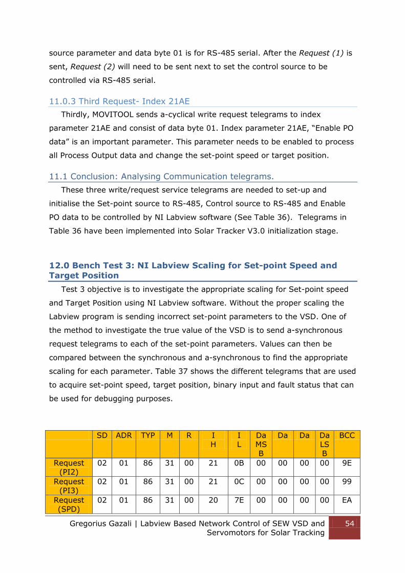
Gregorius Gazali | Labview Based Network Control of SEW VSD and Servomotors for Solar Tracking
54
source parameter and data byte 01 is for RS-485 serial. After the Request (1) is
sent, Request (2) will need to be sent next to set the control source to be
controlled via RS-485 serial.
11.0.3 Third Request- Index 21AE
Thirdly, MOVITOOL sends a-cyclical write request telegrams to index
parameter 21AE and consist of data byte 01. Index parameter 21AE, “Enable PO
data” is an important parameter. This parameter needs to be enabled to process
all Process Output data and change the set-point speed or target position.
11.1 Conclusion: Analysing Communication telegrams.
These three write/request service telegrams are needed to set-up and
initialise the Set-point source to RS-485, Control source to RS-485 and Enable
PO data to be controlled by NI Labview software (See Table 36). Telegrams in
Table 36 have been implemented into Solar Tracker V3.0 initialization stage.
12.0 Bench Test 3: NI Labview Scaling for Set-point Speed and
Target Position
Test 3 objective is to investigate the appropriate scaling for Set-point speed
and Target Position using NI Labview software. Without the proper scaling the
Labview program is sending incorrect set-point parameters to the VSD. One of
the method to investigate the true value of the VSD is to send a-synchronous
request telegrams to each of the set-point parameters. Values can then be
compared between the synchronous and a-synchronous to find the appropriate
scaling for each parameter. Table 37 shows the different telegrams that are used
to acquire set-point speed, target position, binary input and fault status that can
be used for debugging purposes.
SD ADR TYP M R I H
I L
Da MSB
Da Da Da LSB
BCC
Request (PI2)
02 01 86 31 00 21 0B 00 00 00 00 9E
Request (PI3)
02 01 86 31 00 21 0C 00 00 00 00 99
Request (SPD)
02 01 86 31 00 20 7E 00 00 00 00 EA

Gregorius Gazali | Labview Based Network Control of SEW VSD and Servomotors for Solar Tracking
55
Request
(POS)
02 01 86 31 00 20 80 00 00 00 00 14
Request
(BI)
02 01 86 31 00 20 8E 00 00 00 00 1A
Request
(FS)
02 01 86 31 00 20 76 00 00 00 00 E2
Table 37- Drive 1 a-synchronous telegrams
12.0.1 Request (PI2&PI3)
Request (PI2&PI3) telegrams in table 37 are used to obtain the hexadecimal
value of PI2 current speed and current position of the inverter. This value will be
compared to the set-point value (from the synchronous telegram) to obtain the
scaling factors.
12.0.2 Request (SPD)
Request (SPD) telegram in table 37 is used to obtain the current speed of the
inverter. According to the SEW manual, this parameter has conversion index of
66, the raw result from Labview will need to be multiplied by 66 for its true
value. (SEW EURODRIVE 2012)
12.0.3 Request (POS)
Request (POS) telegram in table 37 is used to obtain the current position
values of the inverter. It has no conversion index.
12.0.4 Request (BI)
Request (BI) telegram in table 37 is used to obtain the Binary Input status of
the drives. It consists of 6 binary inputs (DI00-DI05). These binary inputs status
will be helpful for debugging and determining the current status of the drive in
Labview.
12.0.5 Request (FS)
Request (FS) telegram in table 37 will request each drive for the fault status.
If there is no fault status, the response data will consist of hexadecimal 0. For
the fault hexadecimal references please refer to SEW EURODRIVE Field Bus unit
profile with parameter list manual. (SEW EURODRIVE 2000)

Gregorius Gazali | Labview Based Network Control of SEW VSD and Servomotors for Solar Tracking
56
12.1 Trial 1: Comparing Set-point speed with actual read speed from a-
synchronous telegram.
The set-point written and current speed read by NI Labview was incorrect, for
example when Labview request for motor speed of 1000, the feedback from
response telegram was less than 1000. Therefore the aim of trial 1 is to find the
true scaling for set-point speed and actual speed between Labview and VSD.
12.1.0 Set-point speed (PO2) vs Actual Speed (PI2) vs Current Speed
(207E)
The MOVIDRIVE MDX61B speed parameter is a 16 bit integer with range of -
6550 to +6550 and motor limit of 3000 rpm. Scaling has been implemented in
Solar Tracker V3.0. After a series of tests, Table 38 represents the correct
integer scaling for Set-point speed, Actual speed and current speed to show its
true value. The Final Set point value sent to the VSD has to be multiplied by 5,
the data read from VSD must be multiplied by 5 to show its true value and the
current speed a-synchronous information has to be multiplied by 1.667x10⁻⁵ .
(SEW EURODRIVE 2000)
Set-point speed (scaling)
Actual Speed (scaling)
Current Speed (scaling)
5 5 1.667x10⁻⁵ Table 38-Verification test for the correct Speed scaling
12.2 Trial 2: Comparing Target position with current and actual position
Prior to trial 2, the information of motor position was incorrect; the objective
of trial 2 was to find the true scaling for set-point position and actual position.
12.21 Target Position (PO3) vs Actual Position (PI3) vs Current Position
(2080)
The actual position of the drive is represented as a 32bit integer. PO3 and PI3
3600 digit increment will relate to 1 revolution and 1˚ rotation will relate to 10
digits increment (3600/360). Current Position (2080hex) has no conversion index;
hence no scaling is needed (SEW EURODRIVE 2012). In Solar Tracker V 3.0
program, the position can only be controlled in digit increments. Motor indicator
in degrees and radians has been implemented in Solar Tracker V3.0 for feedback
purposes.

Gregorius Gazali | Labview Based Network Control of SEW VSD and Servomotors for Solar Tracking
57
Table 39 represent the correct scaling for each of the servomotors. For DS56M
motor 3600 digit increment in Labview software will give 1 motor revolution,
meanwhile for CFM71S motor, 230 digit increments will give 1 motor revolution.
DS56M has two gear boxes attached to the motor, it gives more resolution
compared to the one-geared CFM71S.
Motor Type Degrees(˚) Labview Digit Increment
DS56M 360 ±3600
CFM71S 360 ±230 Table 39- DS56M & CFM71S motor position scaling
12.3 Conclusion: Trial 1 and 2
A-cyclical telegrams can be used to request VSD parameters and it is useful
for feedback purposes. It requests VSD parameters; such as current speed,
current position, binary inputs and fault status of the VSD. The response
telegram will consist of a 12 byte hexadecimal string, in which only byte 8, 9,
10, 11 contains the information data. Current Speed will be represented as a 16
bit integer, Current Position will be represented as a 32 bit integer and Binary
Input will be represented as a 8 bit Boolean. Hence a proper conversion of bytes
8, 9, 10 and 11 has been implemented to represent correct information. A-
cyclical telegrams have been implemented in Solar Tracker V3.0 “DoNothing”
case statement. (See Figure 58)
Figure 58- A-synchronous telegrams in "DoNothing" case statement
13.0 Bench Test 4: NI Labview Solar Positoning Algorithm
The objective of bench test 4 is to verify the functionality of the Solar
Positioning Algorithm (SPA) that was implemented by Rhyss Edwards in his 2011
Thesis and the final motor positioning as intended in this thesis. Rhyss has
implemented the SPA equations that will calculate the Azimuth and Zenith angle
of the Sun during that instance. However, the functionality of the SPA was not
verified

Gregorius Gazali | Labview Based Network Control of SEW VSD and Servomotors for Solar Tracking
58
13.01 Trial 1: 24 hour Data Logging
The first step to verifying the SPA is to create a data logging loop in Labview
that constantly logs the position of both the Tilt and Roll inverters every minute
into a CSV file for 24 hours. The data logged will then be compared against the
calculated Azimuth and Zenith angles at that instance to confirm its accuracy.
13.02 Trial 1: Results incorrect Night Stow argument
The Solar Positioning Algorithm calculates the new position of the sun,
constantly updates the VSDs and then logs the position of the tilt and roll
inverters. After studying the logged data, a problem was found. The exit case
statement for Night Stow case was incorrect. The original exit case statement
only compares the current time, it is not robust, because as soon as the date roll
over (12AM) the current time will be greater than the Sunset time and will
immediately exit the loop (See Figure 59&60). The complete results from bench
test trial 1 are provided in Appendix E.
Figure 59- Solar Bench Test location during Night Stow
Figure 60- Incorrect tracking during 12AM
A new exit case argument for Night Stow case statements was implemented as
shown in Figure 61; with the Date and Time now being compared against the
time of Sunrise.
Figure 61- New Night Stow loop exit argument

Gregorius Gazali | Labview Based Network Control of SEW VSD and Servomotors for Solar Tracking
59
The Figure 62 and 63 are the verification that the new exit case argument for
night stow is successful , the new program relocates the Night Stow position
(Tilt: 1700, Roll: 1800) at Sunset 6:17PM and starts tracking during the Sunrise.
Figure 62- Correct Solar Tracking Controller V3.0
Figure 63- Normal Tracking mode during Sunrise
13.1 Conclusion: SPA
The SPA has been verified and is ready for the final implementation. During
normal tracking operation, the Solar Tracker V3.0 program will control the Tilt
motor Position from 800 to 1060 and Roll motor Position from 3300 to 3160 by
sending the appropriate telegrams to VSD IPOS controller. In the future,
appropriate scaling between gear ratios and the final system will need to be
investigated, to ensure that the calculated angles by SPA are appropriate for the
system.
14.0 Break down of Solar Tracker V3.0 NI Labview program
Solar Tracker V3.0 is the most up to date and verified version of the solar
tracking controller program. It represents an overhauled program from the
previous Solar Tracker V2.0, with similar aspects. There are five main stages in
the solar tracking program:
Initialization
Send Request (Automatic, Jog, Reference, Setup/INHIBIT, Advance)
Get Response
Process Message
Do Nothing (A-synchronous telegrams)
Different VSD addresses will be controlled by Labview in different loops. During a
true case, VSD address 1 is controlled by Labview and VSD address 2 is

Gregorius Gazali | Labview Based Network Control of SEW VSD and Servomotors for Solar Tracking
60
controlled during the false case. An indicator is provided in the operator view for
feedback purposes. (See Figure 64)
Figure 64- VSD controlled indicator
14.1 Initialization Stage
The Initialization stage objective is to open communications of COM-PORT 5
or 6 (at the moment two connections are connected on the same terminal block,
but only one comport can be controlled by Labview.) with NI Labview VISA serial
with 9600 baud rate, 8 data bits, 1 stop bits, no termination characters and even
parity.
The initialization consists of 12 For Loops and 12 case statements that consist of
write and read pair telegrams. The first case (case 0) will write Request (1) to
Drive 1 and wait for the Response (1) telegram from the inverter. The case will
repeat for Request (2) Response (2), Request (3) Response (3), and so on. Case
6 to 11 will be used for Driver 2 initialization parameters. The initialization stage
will complete itself before moving on to the next stage Send Request. The
initialization stage runs only once at the start of the program. (See Table 36)
Figure 65- Labview Initialization stage to control MOVIDRIVE with NI Labview
Figure 65 depicts the initialization loop, more information about the Solar
Tracker 3.0 program can be found in Appendix B.
14.2 Send Request Loop
The Send request stage will send the request telegrams to the individual
inverters. Request telegrams will consist of inverter address, control word, set-
point speed and target position. The program is designed so that every first loop

Gregorius Gazali | Labview Based Network Control of SEW VSD and Servomotors for Solar Tracking
61
is for address 1 VSD and every second loop is for address 2 VSD. The current
loop is set on 500ms interval and theoretically is more than adequate for the
system as the Sun only moves 15˚ every hour. (National Renewable Energy
Laboratory 2010)
14.3 Reference Mode
Reference mode is an important stage as it keeps the tracking system
accurate and pointing at the Sun position. Reference mode should be run once a
week just before sun rise. To enable reference mode in Labview the reference
tab has to be activated. Solar Tracker V3.0 is designed so that reference mode
has to be executed first before any other operations. The control word for
reference mode is 1106hex and reference mode for each VSD is set as Reference
Mode 1: Counter Clockwise (CCW) Reference Cam. When reference mode is
activated the inverter will rotate in CCW direction at 600(1/min), it will keep
running until the reference cam signal (X13:4) is pulsed. After reference is
completed, the reference position output LED will be activated. In the future an
automatic reference mode can be implemented at the start of every Monday or
at controller desired frequency.
14.4 Automatic mode [Tracking]
The automatic mode is the main tracking program; it continuously calculates
the Azimuth and Zenith angle of the sun by using the SPA. The raw Azimuth and
Zenith angle is converted into radians in Labview, then converted into positional
(integer) information in Labview by multiplying Azimuth and Zenith angle by 10
(1 degrees = 10 digit). The Labview Controller updates the position of the
tracking system according to the sun position every minute. A manual update
button (See Figure 66) has been included to immediately update the position for
the Tilt and Roll servomotors. Further investigation is needed to verify the
conversion of Azimuth and Zenith angles. This can only be done once the system
is implemented in the PV Through Area.

Gregorius Gazali | Labview Based Network Control of SEW VSD and Servomotors for Solar Tracking
62
Figure 66- Automatic Mode Panel
14.5 Automatic mode [Manual Stow / Cleaning]
Objective of Manual Stow / Cleaning mode is to stow the tracking system to a
safe position when the wind speed is above 70 (km/h) for safety purposes.
However this stage can only be carried out once the final system has been
implemented in the PV Through Area, this stage has not yet been completed. An
Anemometer will need to be attached to the system and integrate the
information to the Solar Tracker program and dealt with accordingly.
14.6 Jog Mode
Jog mode can be used to manually control the SEW motors. Set-point speed
of both motors will need to be specified. The forward and backward button
activates the motors at a specific direction (see Figure 67). To deactivate Jog
mode user simply depresses the direction button. The green LED will provide the
feedback information for the user view, when activated the LED will flash.
Figure 67- Jog Mode Panel

Gregorius Gazali | Labview Based Network Control of SEW VSD and Servomotors for Solar Tracking
63
14.7 Setup/INHIBIT mode [Default]
Setup/INHIBIT mode is the default view of the program; it will open the VISA
COM-PORT and communicate to the listed inverter addresses. By default, the
program is set to COM-PORT 6, Tilt address is 1 and Roll address is 2 (See
Figure 68). During a cold/hot start the program will enter Setup/INHIBIT mode.
In this mode, it will immediately stop any running program of the VSD.
Controller Inhibit is the highest priority safety word and can be applied as an
Emergency Stop.
Figure 68- Setup/INHIBIT Panel
14.8 Advance mode [For future use]
Advance mode is for future use and intended for educational purposes. Its
objective is to be able to manually control the operation of the VSD by
supplementing unique sets of SEW telegrams, unlike the current operation
modes all telegrams are hardcoded. This mode has not been completed.
14.9 Get Response Loop
The Get Response loop is designed to read the response telegram from the
VSD at the specified COM-PORT. It will continue to the next stage “Process
Message”, if and only if the telegram length read is 10 bytes. If not, the loop
sequence will continue reading the serial port until 10 bytes are read by the
program. This will ensure the integrity of the response telegram.
14.10 Process Message Loop
The string captured in “Get Response” loop is analysed in this stage. The
string read is converted into 8 bits arrays. The arrays will be indexed (See Table
40) appropriately to extract the control word, actual speed and actual position.
Control word information is 8 bits, while speed and position information are 16
bits word, hence Join Numbers function is used to combine the High 8 bits and
Low 8 bits words. The Inverter status, current speed (1/min) and current

Gregorius Gazali | Labview Based Network Control of SEW VSD and Servomotors for Solar Tracking
64
position (integer/rad/degrees) will be displayed in the front panel of operator
view (See Figure 69). More information is provided in the Appendix B.
Index Number Function Description
4 Control Word Inverters status
5&6 Process Output Speed Inverters Speed status
7&8 Process Output Position Inverters Position
Status Table 40- Process Message Index description
Figure 69- Inverter Status for operator view
14.11 Do Nothing Loop (A-cyclical telegram)
The “Do Nothing Loop” contains a-cyclical telegrams that are used to request
VSD’s parameters for feedback purposes. The a-cyclical information read from
this loop can be compared against synchronous information to study and verify
its values. A-synchronous information can be used to debug synchronous
telegrams.
The a-cyclical telegram will request these parameters:
PI2 - Actual Speed
PI3 - Actual Position
207Ehex - Current Speed
2080hex - Current Position
208Ehex - Binary Inputs
2076hex - Fault Status
Each a-cyclical telegram transactions will require 40 milliseconds wait in between
each service, 20 milliseconds to send request telegram to VSD and 20
milliseconds wait to read the response from VSD. (Please note according to the
manual the telegrams only need 6.4 milliseconds wait between each service,
however for a precautions 20ms wait is implemented to ensure correct

Gregorius Gazali | Labview Based Network Control of SEW VSD and Servomotors for Solar Tracking
65
telegrams exchange.) The a-cyclical loop will slow down the loop time
dramatically due to the wait timer. The current main program loop time is
500ms and it is capable to track the sun accurately. The Sun rotates at an
average rate of 15˚ per hour. (National Renewable Energy Laboratory 2010)
14.12 Data Logging Loop
The data logging loop has been created to log the current date, current time,
set-point Tilt, set-point Roll, sunrise time and sunset time. The current logging
loop time is set to 1 minute interval, the logging loop is coded so that it will run
at an independent rate compared to the main loop so that the logging loop can
log slower than the main loop. In the future, Anemometer, Luxmeter and
Hygrometer can be installed into the Solar Tracking system to measure the wind
speed, sun intensity, humidity and the data can be added. The data logging loop
uses two “Write To Spreadsheet File.v” the first is used to create the title of the
CSV file and the second is used to constantly log the data at 1 minute rate. (See
Figure 70)
Figure 70- Data Logging While loop
15.0 NI Labview Solar Tracker V3.0 Front Panel
The Solar Tracker V3.0 consists of two important front panels, operator view
and debugging view. Operator view located at the most left hand side and the
debugging view is located at the right hand side. A more descriptive explanation
is provided in Appendix B.

Gregorius Gazali | Labview Based Network Control of SEW VSD and Servomotors for Solar Tracking
66
15.1 Operator View
Operator view is the main view that operator uses in order to interact with
the program; it displays the following information, (See Figure 71):
Heartbeat Simulator - Shows the current stage of the
program
Which VSD LED - Display which VSD is being controlled
Motor position indicator - Indicates motor position in decimal,
degree and radians
Binary inputs and outputs
indicators
- Indicate the status of the system
Telegram Service View - Indicate the current request and
response telegram
Error Indicators - Indicates Telegram structure or BCC
error
Data Logging Panel - Control panel for data logging loop
Figure 71- Operator Visual Component
More information about solar tracker V3.0 can be found in Appendix B.

Gregorius Gazali | Labview Based Network Control of SEW VSD and Servomotors for Solar Tracking
67
15.2 Debugging Panel
Debugging Panel can be used to debug any problem with telegrams service,
as it displays all cyclical and a-cyclical response telegrams from each VSD.
During normal operation all the boxes in the Debugging panel should be
populated. In any situation where information is missing from one of the boxes,
the VSD did not receive the request telegram correctly and hence a hard-reset of
the program is required. To eliminate telegrams failure, the minimum loop cycle
should be 500ms. (See Figure 72)
Figure 72- Debugging View
15.3 A-Cyclical Data Panel
A-cyclical data panel is located at the right hand side of the debugging panel.
It is used to obtain parameters such as. Binary Inputs and fault status from each
of the inverters. It can be used as a debugging tool, by obtaining values from a-
cyclical telegrams and compare them with the cyclical telegrams. A-cyclical
telegram was investigated to study the behaviour and property of a-cyclical
telegram of the MOVILINK Protocol. (See Figure 72)

Gregorius Gazali | Labview Based Network Control of SEW VSD and Servomotors for Solar Tracking
68
16.0 Conclusion and Future Objectives
In this thesis project, Labview Solar Tracker Controller has been updated to
version 3.0 and able to control Automatic, Jog and reference mode of the VSD
by sending the appropriate request telegrams. In version 2.0, the Labview
controller was incomplete and was only able to read parameters from the
inverters and no writing telegrams were being executed. This issue has been
fixed by implementing initialization telegrams that initialises the VSD to be
controlled via RS485 connection, enable process data values, implement the
correct telegrams and added the correct BCC character into the end of the
telegrams.
To control SEW inverters through RS-485 communication, NI Labview needs to
request valid sets of telegrams. IPOS plus Automatic, Reference and Jog mode
can be controlled via 10 cyclical telegrams bytes, with the telegrams consisting
of a control word, target position and set-point speed. A-cyclical telegrams were
also investigated in the project, with the 12 byte telegram was used to read
VSD’s parameters such as, binary inputs, actual speed, set-point and fault
status.
Two types of MDX61B VSD are investigated in this project, version 0005 and
0011. MDX61B-0005 is dedicated for the smaller DS56M servomotor and
MDX61B-0011 is suitable for the bigger CFM71S servomotor. The Roll frame has
been erected in the PV Trough area with CFM71S SEW motor attached on its
shaft, three phase power supply lines has connected through the underground
cable system. However it has not been attached to the main grid. In the future,
Tilt frame will need to be mounted along with DS56M motor attached to its
shaft.
The Project is at its final stage of implementation, with the backbone program
“Solar Tracking V3.0” completed, the next project holder can concentrate on
implementing the “small” solar tracking system in PVT area. Future work such
as, attaching the tilt frame, attaching DS56M motor to tilt shaft, implementing
electrical cabinet, implementing MDX61B VSD and master computer to the

Gregorius Gazali | Labview Based Network Control of SEW VSD and Servomotors for Solar Tracking
69
electrical cabinet and ultimately tuning the Labview Solar Tracker v3.0
controller.
Future work includes:
Error detection and recovery of the solar tracker program
Reference mode of the actual system
Scaling of the Labview program and comparing it to the actual system.
Further future directions and tutorials are provided in the appendixes.
17.0 List of Appendices
All the appendices are attached electronically and located in the engshared. Appendix A - Figures
Appendix B - Labview Tutorials & Program
Appendix C - SEW Emails
Appendix D - SEW Documents and Manuals
Appendix E - Bench Test results Appendix F - MOVITOOL Tutorials
Appendix G - MOVILINK Telegrams
Appendix H – Future Objectives
Appendix I - Electrical Cabinet
Appendix J - Project Proposal & Progress Appendix K - Previous Project holders
Appendix L – Tutorial installing new MDX61B inverter

Gregorius Gazali | Labview Based Network Control of SEW VSD and Servomotors for Solar Tracking
70
Bibliography
Australian Government. Solar Energy. 2014. http://arena.gov.au/about-renewable-energy/solar-energy/ (accessed 08 25, 2014).
B&B Electronics. RS485 Protocol Basics. 2014. http://www.bb-elec.com/Learning-Center/All-White-Papers/Serial/Basics-of-the-RS-485-Standard.aspx (accessed 08 03, 2014).
BOM. Average Sun Shine. 2014. http://www.bom.gov.au/jsp/ncc/climate_averages/sunshine-
hours/index.jsp (accessed 10 28, 2014). Edwards, Rhyss. Control System design and commissioning of photovoltaic
through concentrator systems installed at the Murdoch University South St
Campus. Perth: Murdoch University, 2010. Green Street Solar. Green Street Solar. 2014.
http://www.greenstreetsolar.com/sites/default/files/azelzen.gif (accessed 08 25, 2014).
JC Solar homes. JC Solar Homes. 2014. http://www.jc-
solarhomes.com/COLLECTORS/concentrators/trough1.jpg (accessed 08 25, 2014).
National Renewable Energy Laboratory. Solar Position Algorithm for Solar Radiation Applications. Technicall Report, Colorado: Golden, 2010.
NI Labview. USB- RS48 Pin out. 2007.
http://www.ni.com/pdf/manuals/371253c.pdf (accessed 08 01, 2014). SEW EURODRIVE. 2010. http://download.sew-
eurodrive.com/download/pdf/17014417_G05.pdf (accessed 09 11, 2014). SEW EURODRIVE. Catalog Gear Units. SEW EURODRIVE, 2010. SEW EURODRIVE. “DFS/CFM Synchronous Servomotors Operating Instructions.”
2008. SEW EURODRIVE. Fieldbus Unit Profile with Parameter List. SEW EURODRIVE,
2000. SEW EURODRIVE. IPOS-Plus Positioning and Sequence Control System. SEW
Eurodrive, 2012.
SEW EURODRIVE. MOVIDRIVE Serial Communication. SEW EURODRIVE, 2001. SEW Eurodrive. Operating Instructions Movidrive MDX60B/61B. SEW Eurodrive,
2010. SEW EURODRIVE. “SEW encoder systems.” 1999. SEW EURODRIVE. The DS/CM Synchronous Servomotor from SEW-EURODRIVE.
SEW EURODRIVE, 2010. Sibson, Jarrad. Using Variable Speed Drives, Servo Motors and RS-485
Communication in a Solar Tracking System for Educational Purposes. Perth: Murdoch University, 2012.