Laboratory Performance Evaluation Report of SEL 421 Phasor
59
PNNL-16852 Laboratory Performance Evaluation Report of SEL 421 Phasor Measurement Unit Z. Huang T. Faris K. Martin J.F. Hauer C.A. Bonebrake J.M. Shaw December 2007 Prepared for the U.S. Department of Energy under Contract DE-AC05-76RL01830
Transcript of Laboratory Performance Evaluation Report of SEL 421 Phasor
PNNL-16852
Laboratory Performance Evaluation Report of SEL 421 Phasor Measurement Unit Z. Huang T. Faris K. Martin J.F. Hauer C.A. Bonebrake J.M. Shaw December 2007 Prepared for the U.S. Department of Energy under Contract DE-AC05-76RL01830
DISCLAIMER This report was prepared as an account of work sponsored by an agency of the United States Government. Neither the United States Government nor any agency thereof, nor Battelle Memorial Institute, nor any of their employees, makes any warranty, express or implied, or assumes any legal liability or responsibility for the accuracy, completeness, or usefulness of any information, apparatus, product, or process disclosed, or represents that its use would not infringe privately owned rights. Reference herein to any specific commercial product, process, or service by trade name, trademark, manufacturer, or otherwise does not necessarily constitute or imply its endorsement, recommendation, or favoring by the United States Government or any agency thereof, or Battelle Memorial Institute. The views and opinions of authors expressed herein do not necessarily state or reflect those of the United States Government or any agency thereof.
PACIFIC NORTHWEST NATIONAL LABORATORY operated by BATTELLE
for the UNITED STATES DEPARTMENT OF ENERGY
under Contract DE-AC0576RL01830
Printed in the United States of America
Available to DOE and DOE contractors from the Office of Scientific and Technical Information,
P.O. Box 62, Oak Ridge, TN 37831-0062; ph: (865) 576-8401 fax: (865) 576-5728
email: [email protected]
Available to the public from the National Technical Information Service, U.S. Department of Commerce, 5285 Port Royal Rd., Springfield, VA 22161
ph: (800) 553-6847 fax: (703) 605-6900
email: [email protected] online ordering: http://www.ntis.gov/ordering.htm
This document was printed on recycled paper. (8/00)

Laboratory Performance Evaluation Report of SEL 421 Phasor Measurement Unit (PMU) Z. Huang T. Faris(1) K. Martin(1) J.F. Hauer C.A. Bonebrake J.M. Shaw December 2007 Prepared for the U.S. Department of Energy Under Contract DE-AC05-76RL01830
Pacific Northwest National Laboratory Richland, Washington 99352 ____________ (1) Bonneville Power Administration, Measurement Systems Group
iii
SUMMARY Technology evaluation is a major element of the wide area measurement system (WAMS) effort to enhance measurement-based information resources for managing large power grids. Critical measurement devices, such as phasor measurement units (PMUs) and other advanced transducers, are evaluated through a combination of model studies, laboratory tests, and performance comparisons under field conditions. Laboratory evaluation of PMU performance has the following immediate objectives:
A. Determine whether the PMU provides data of acceptable quality across a sufficiently broad frequency range.
B. Determine PMU response in sufficient detail that its behavior can be predicted over a full range of application conditions, many of which cannot be reproduced with laboratory tests.
Specific attention must be given to performance measures laid out in established guidelines or standards, such as the WECC phasor measurement requirements and the IEEE SynchroPhasor Standard C37.118. This report presents the laboratory evaluation results of the SEL 421 PMU unit. The laboratory evaluation focuses only on the phasor measurement functionality of the SEL 421 unit. Though SEL 421 is capable of performing relay functions, they are beyond the scope of this report. The laboratory evaluation described in this report was performed with a standard relay test set using recorded files of precisely generated test signals. Test signals include steady-state waveforms to test amplitude, phase, and frequency accuracy; modulated signals to determine measurement and rejection bands; and step tests to determine timing and response accuracy. The SEL 421 PMU unit has two filtering options: Narrow Band and Fast Response. It also has a frequency compensation function, which can be enabled or disabled by users. All four setting combinations are examined in the report, in test series A through D:
Test Series A: Narrow Band with Frequency Compensation off Test Series B: Narrow Band with Frequency Compensation on Test Series C: Fast Response with Frequency Compensation off Test Series D: Fast Response with Frequency Compensation on
The measurement accuracy for magnitude, phase and frequency of three-phase balanced voltage and current signals complies with both level 0 and level 1 requirements established in the IEEE SynchroPhasor Standard C37.118, except that frequency measurement with Test Series A does not meet level 1 requirements. Harmonic and out-of-band signal rejection performance with all four Test Series complies with level 0 requirements, while only Narrow Band setting achieves level 1 compliance. Dynamic performance for SEL 421with Narrow Band filtering is very close to satisfying the WECC phasor measurement requirements. This is not the case for Fast Response filtering. Time delay with amplitude and phase modulation signals is about 2 ms on average with a maximum deviation of about 10 ms. Time delay with frequency modulation signals is about 80 ms with a maximum deviation about 1 ms. Fast Response filtering shows faster rising response in step tests than Narrow Band filtering, with the rising time being about 33 ms versus about 60 ms. Different PMU settings result in different measurement performance with certain advantages and disadvantages. In practical applications, the best PMU setting should be determined with consideration of specific application requirements.
iv
Table of Contents SUMMARY.................................................................................................................................................iii 1.0 PREFACE.............................................................................................................................................. 1 2.0 INTRODUCTION ................................................................................................................................. 2 3.0 SUMMARY OF TEST RESULTS........................................................................................................ 6
3.1 Measurement Accuracy Summary ................................................................................................. 6 3.2 Harmonic and Out-of-Band Signal Rejection Summary ............................................................. 7 3.3 Modulated Signal Test Summary ................................................................................................... 8 3.4 Step Test Summary ........................................................................................................................ 10 3.5 Relative Timing Summary ............................................................................................................ 12
4.0 DETAILS OF TEST RESULTS AND MEASUREMENT PLOTS.................................................... 13 4.1 Magnitude Accuracy...................................................................................................................... 13 4.2 Phase Angle Measurement ............................................................................................................ 14
4.2.1 Phase Angle at Nominal Frequency.......................................................................................... 14 4.2.2 Phase Angle Measurement Variation with Frequency.............................................................. 14
4.3 Frequency Response – Measurement Band ................................................................................. 15 4.4 Frequency Accuracy ...................................................................................................................... 16 4.5 Measurement of Unbalanced Signals ........................................................................................... 18
4.5.1 Amplitude Unbalance ............................................................................................................... 18 4.5.2 Phase Unbalance ....................................................................................................................... 19
4.6 Harmonic Rejection ....................................................................................................................... 20 4.7 Single Frequency Out-of-Band Rejection .................................................................................... 23 4.8 Amplitude Modulation .................................................................................................................. 23
4.8.1 Amplitude Modulation with Nominal Frequency ..................................................................... 23 4.8.2 Amplitude Modulation with off-Nominal Frequency ............................................................... 25
4.9 Phase Modulation........................................................................................................................... 28 4.10 Frequency Modulation ................................................................................................................ 30 4.11 Step Tests ...................................................................................................................................... 32
4.11.1 Amplitude Step Test ............................................................................................................... 32 4.11.2 Phase Step Test ....................................................................................................................... 34 4.11.3 Frequency Step Test................................................................................................................ 35
5.0 TIMING VERSUS REFERENCE PMUS ........................................................................................... 37 6.0 REFERENCES .................................................................................................................................... 39 APPENDIX A: WECC Requirements for Monitoring Equipment............................................................. 41 APPENDIX B: IEEE Guidelines for PMU Performance........................................................................... 45 APPENDIX C: PMU Types Used in Performance Comparisons ............................................................... 47
C.1 General Characteristics of the Macrodyne 1690M .................................................................... 47 C.2 General Characteristics of the ABB RES521 ............................................................................. 50

v
Figures Figure 1. SEL 421 PMU vs. WECC Filtering Standard ............................................................................. 3 Figure 2. PMU Frequency Signals for 1.4 Hz Amplitude Modulation........................................................ 3 Figure 3. Steady -State Magnitude Response for Voltage .......................................................................... 13 Figure 4. Steady-State Magnitude Response for Current ........................................................................... 13 Figure 5. Steady-State Phase Angle Response............................................................................................ 14 Figure 6. Phase Angle vs. Frequency.......................................................................................................... 15 Figure 7. Steady-State Frequency Response over the Range of 0 to 300 Hz.............................................. 15 Figure 8. Steady -State Frequency Response over the Pass Band .............................................................. 16 Figure 9. Steady-State Frequency Response over the Range of 59 to 61 Hz.............................................. 16 Figure 10. Frequency Measurement Error over the Reporting Range of 45 to 70 Hz ................................ 17 Figure 11. Frequency Measurement Error over the Range of 55 to 65 Hz................................................ 17 Figure 12. Frequency Measurement Error over the Reporting Range of 59 to 61 Hz ................................ 17 Figure 13. Unbalanced Amplitude Response, Narrow Band with Frequency Compensation on ............... 18 Figure 14. Unbalanced Amplitude Response, Fast Response with Frequency Compensation off ............. 18 Figure 15. Unbalanced Amplitude Response at 60 Hz ............................................................................... 19 Figure 16. Unbalanced Phase Response, Narrow Band with Frequency Compensation on ....................... 19 Figure 17. Unbalanced Phase Response, Fast Response with Frequency Compensation off ..................... 20 Figure 18. Unbalanced Phase Response at 60 Hz....................................................................................... 20 Figure 19. Response to Harmonic Distortion, Narrow Band, Frequency Compensation on ...................... 21 Figure 20. Response to Harmonic Distortion, Narrow Band, Frequency Compensation off...................... 21 Figure 21. Response to Harmonic Distortion, Fast Response, Frequency Compensation on..................... 22 Figure 22. Response to Harmonic Distortion, Fast Response, Frequency Compensation off .................... 22 Figure 23. Response to Harmonic Distortion at 60 Hz ............................................................................... 22 Figure 24. Response to Single Out-of-Band Distortion.............................................................................. 23 Figure 25. Response to Amplitude, 0 to 15 Hz........................................................................................... 24 Figure 26. Amplitude Modulation Response, 15 to 180 Hz ....................................................................... 24 Figure 27. Phase Delay of Amplitude Modulation Tests............................................................................ 25 Figure 28. Phase Angle of Amplitude Modulation Tests............................................................................ 25 Figure 29. Off-Nominal Amplitude Modulation Response with the Setting of Fast Response, Frequency Compensation on ........................................................................................................................................ 26 Figure 30. Off-Nominal Amplitude Modulation Response with the Setting of Fast Response, Frequency Compensation off........................................................................................................................................ 27 Figure 31. Off-Nominal Amplitude Modulation Response with the Setting of Narrow Band Response, Frequency Compensation off ...................................................................................................................... 28 Figure 32. Phase Modulation Response, 0 to 15 Hz ................................................................................... 29 Figure 33. Phase Modulation Response, 15 to 180 Hz ............................................................................... 29 Figure 34. Delay of Phase Modulation Tests.............................................................................................. 30 Figure 35. Phase Angle of Phase Modulation Tests ................................................................................... 30 Figure 36. Frequency Modulation Response, 0 to 15 Hz............................................................................ 31 Figure 37. Frequency Modulation Response, 15-180 Hz ........................................................................... 31 Figure 38. Delay of Frequency Modulation Test........................................................................................ 32 Figure 39. Positive Amplitude Step Response for Voltage......................................................................... 32 Figure 40. Negative Amplitude Step Response for Voltage ....................................................................... 33 Figure 41. Positive Amplitude Step Response for Current ......................................................................... 33 Figure 42. Negative Amplitude Step Response for Current ....................................................................... 34 Figure 43. Positive Phase Angle Step Response......................................................................................... 34 Figure 44. Negative Phase Angle Step Response ....................................................................................... 35 Figure 45. Positive Frequency Step Response ............................................................................................ 35
vi
Figure 46. Negative Frequency Step Response .......................................................................................... 36 Figure 47. PMU Frequency Signals for 1.4 Hz Amplitude Modulation, Test Series A ............................ 38 Figure 48. Relative Phase of PMU Frequency Signals for 1.4 Hz Amplitude Modulation, Test Series A 38 Figure 49. 12 Hz Butterworth Filter vs. WECC Filtering Standard............................................................ 42 Figure 50. 6 Hz Butterworth Filter vs. WECC Filtering Standard.............................................................. 43 Figure 51. Two Stage Fourier Filter Approximating that of the Macrodyne 1690M PMU....................... 47 Figure 52. Model PMU_Box1X4X30 vs. Measured Response for the Macrodyne 1690M...................... 48 Figure 53. Macrodyne 1690M vs. WECC Filtering Standard ................................................................... 48 Figure 54. Modulation of Balanced 60.06 Hz Carrier, Macrodyne 1690M............................................... 49 Figure 55. Modulation of Balanced 60.06 Hz Carrier, PMU Model PMU_Box1&4X30 ......................... 49 Figure 56. ABB RES4521 Filter Options (Adaptive Logic off) ................................................................ 50 Figure 57. PMU Voltage Response to AM Modulation Scan:................................................................... 51 Figure 58. PMU Frequency Response to AM Modulation Scan: .............................................................. 51
vii
Tables Table 1. SEL 421 Settings* .......................................................................................................................... 5 Table 2. Measurement Accuracy with the Setting of Narrow Band, Frequency Compensation on ............. 6 Table 3. Measurement Accuracy with the Setting of Narrow Band, Frequency Compensation off............. 6 Table 4. Measurement Accuracy with the Setting of Fast Response, Frequency Compensation on ........... 7 Table 5. Measurement Accuracy with the Setting of Fast Response, Frequency Compensation off ........... 7 Table 6. Harmonic and Out-of-Band Signal Rejection Summary with the Setting of Narrow Band, Frequency Compensation on......................................................................................................................... 8 Table 7. Harmonic and Out-of-Band Signal Rejection Summary with the Setting of Narrow Band, Frequency Compensation off ........................................................................................................................ 8 Table 8. Harmonic and Out-of-Band Signal Rejection Summary with the Setting of Fast Response, Frequency Compensation on......................................................................................................................... 8 Table 9. Harmonic and Out-of-Band Signal Rejection Summary with the Setting of Fast Response, Frequency Compensation off ........................................................................................................................ 8 Table 10. Modulated Signal Test Summary in the Pass Band with the Setting of Narrow Band, Frequency Compensation on – Pass Band ...................................................................................................................... 9 Table 11. Modulated Signal Test Summary in the Pass Band with the Setting of Narrow Band, Frequency Compensation on – Out-of-Band Rejection.................................................................................................. 9 Table 12. Modulated Signal Test Summary in the Pass Band with the Setting of Narrow Band, Frequency Compensation off – Pass Band ..................................................................................................................... 9 Table 13. Modulated Signal Test Summary in the Pass Band with the Setting of Narrow Band, Frequency Compensation off – Out-of-Band Rejection ................................................................................................. 9 Table 14. Modulated Signal Test Summary in the Pass Band with the Setting of Fast Response, Frequency Compensation on – Pass Band .................................................................................................. 10 Table 15. Modulated Signal Test Summary in the Pass Band with the Setting of Fast Response, Frequency Compensation on – Out-of-Band Rejection ..............................................................................10 Table 16. Modulated Signal Test Summary in the Pass Band with the Setting of Fast Response, Frequency Compensation off – Pass Band ................................................................................................. 10 Table 17. Modulated Signal Test Summary in the Pass Band with the Setting of Fast Response, Frequency Compensation off – Put-of-Band Rejection .............................................................................. 10 Table 18. Step Test Summary with the Setting of Narrow Band, Frequency Compensation on ................ 11 Table 19. Step Test Summary with the Setting of Narrow Band, Frequency Compensation off ............... 11 Table 20. Step Test Summary with the Setting of Fast Response, Frequency Compensation on............... 11 Table 21. Step Test Summary with the Setting of Fast Response, Frequency Compensation off .............. 12 Table 22. Relative Delays of PMU Frequency Signals for 1.4 Hz Angle Modulation, Test Series A ...... 12 Table 23. Relative Delays of PMU Frequency Signals for 1.4 Hz Angle Modulation, Test Series A ...... 37 Table 24. Relative Delays of PMU Frequency Signals for 0.28 Hz Angle Modulation, Test Series A .... 37 Table 25 Influence Quantities and Allowable Error Limits for Compliance Levels 0-1. .......................... 45
1
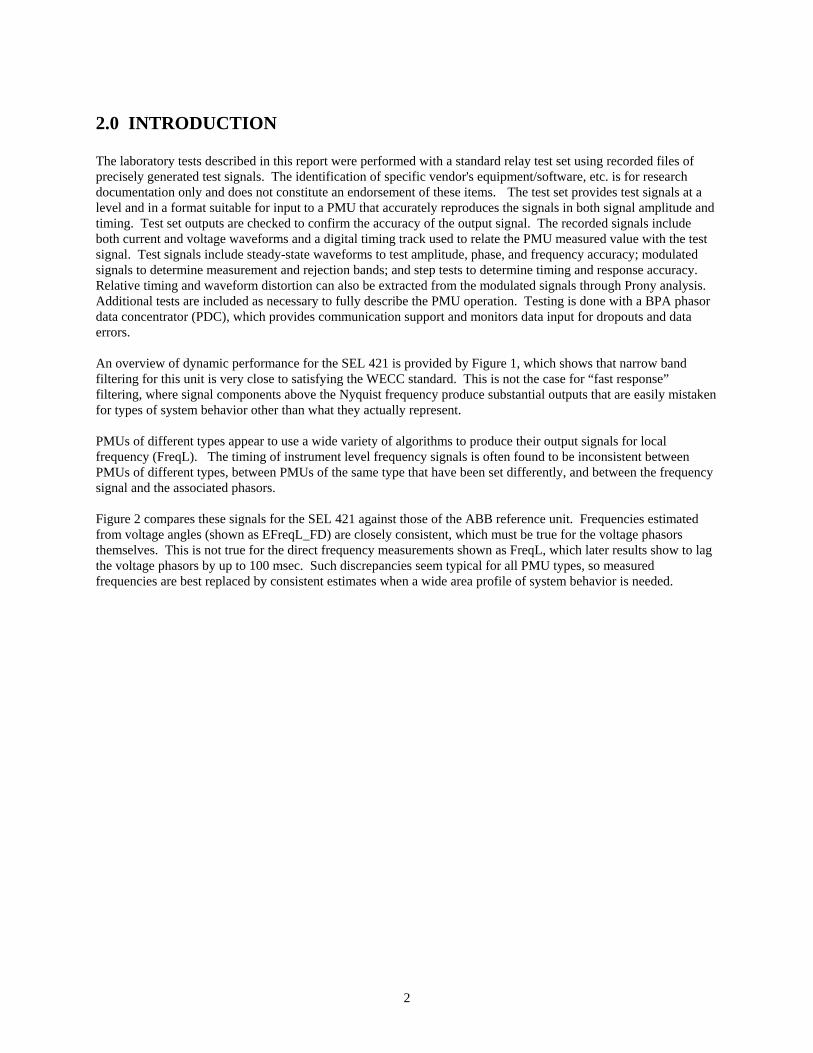
1.0 PREFACE Technology evaluation is a major element of the wide area measurement system (WAMS) effort to enhance measurement-based information resources for managing large power grids (Bonneville Power Administration 1999, Hauer et al. 2007). Critical measurement devices, such as phasor measurement units (PMUs) and other advanced transducers, are evaluated through a combination of model studies, laboratory tests, and performance comparisons under field conditions (Martin 1992, Hauer 1996, Hauer, et al. 2004). New or revised PMU types are often tested in tandem with other PMU types (or PMU models) that are well understood, and in common use. This provides cross calibration data that may be needed to adjust some measurements to achieve better consistency among different instrument types (Hauer 2001). Also, by comparing results from the unit against those of earlier tests, one can readily establish that the present tests are being performed consistently. Reference units for the Western Electricity Coordinating Council (WECC) purposes are usually Macrodyne 1690M, a simulation model (called PMU_Box1X4X30) that closely replicates dynamic response of the 1690M (Hauer et al 2004), and the ABB RES521. As mentioned above, we use them as reference units because they are well-understood PMU types and models. The use of them as reference units does not imply any superior performance over others. Bonneville Power Administration (BPA) installations of this ABB unit usually set it for filter #2 and frequency tracking on. Laboratory evaluation of PMU performance has the following immediate objectives:
A. Determine whether the PMU provides data of acceptable quality across a sufficiently broad frequency range.
B. Determine PMU response in sufficient detail that its behavior can be predicted over a full range of application conditions, many of which cannot be reproduced with laboratory tests.
Laboratory tests should characterize PMU performance to the degree that, when needed, an approximate model can be developed for its signal processing algorithm(s). Specific attention must also be given to performance measures laid out in established guidelines or standards, as established by the WECC and the Institute of Electrical and Electronics Engineers (IEEE) (Martin 2004, IEEE Standard 2006).
2
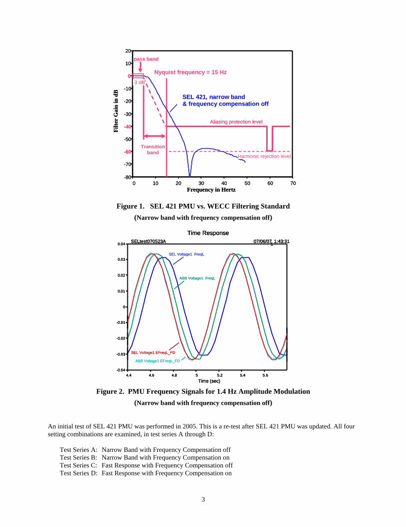
2.0 INTRODUCTION The laboratory tests described in this report were performed with a standard relay test set using recorded files of precisely generated test signals. The identification of specific vendor's equipment/software, etc. is for research documentation only and does not constitute an endorsement of these items. The test set provides test signals at a level and in a format suitable for input to a PMU that accurately reproduces the signals in both signal amplitude and timing. Test set outputs are checked to confirm the accuracy of the output signal. The recorded signals include both current and voltage waveforms and a digital timing track used to relate the PMU measured value with the test signal. Test signals include steady-state waveforms to test amplitude, phase, and frequency accuracy; modulated signals to determine measurement and rejection bands; and step tests to determine timing and response accuracy. Relative timing and waveform distortion can also be extracted from the modulated signals through Prony analysis. Additional tests are included as necessary to fully describe the PMU operation. Testing is done with a BPA phasor data concentrator (PDC), which provides communication support and monitors data input for dropouts and data errors. An overview of dynamic performance for the SEL 421 is provided by Figure 1, which shows that narrow band filtering for this unit is very close to satisfying the WECC standard. This is not the case for “fast response” filtering, where signal components above the Nyquist frequency produce substantial outputs that are easily mistaken for types of system behavior other than what they actually represent. PMUs of different types appear to use a wide variety of algorithms to produce their output signals for local frequency (FreqL). The timing of instrument level frequency signals is often found to be inconsistent between PMUs of different types, between PMUs of the same type that have been set differently, and between the frequency signal and the associated phasors. Figure 2 compares these signals for the SEL 421 against those of the ABB reference unit. Frequencies estimated from voltage angles (shown as EFreqL_FD) are closely consistent, which must be true for the voltage phasors themselves. This is not true for the direct frequency measurements shown as FreqL, which later results show to lag the voltage phasors by up to 100 msec. Such discrepancies seem typical for all PMU types, so measured frequencies are best replaced by consistent estimates when a wide area profile of system behavior is needed.
3
0 10 20 30 40 50 60 70-80
-70
-60
-50
-40
-30
-20
-10
0
10
20
Nyquist frequency = 15 Hz
Transitionband
pass band
Aliasing protection level
Frequency in Hertz
Filte
r G
ain
in d
B
-3 dB
Harmonic rejection level
SEL 421, narrow band & frequency tracking off
-3 dB
0 10 20 30 40 50 60 70-80
-70
-60
-50
-40
-30
-20
-10
0
10
20
Nyquist frequency = 15 Hz
Transitionband
pass band
Aliasing protection level
Frequency in Hertz
Filte
r G
ain
in d
B
-3 dB
Harmonic rejection level
SEL 421, narrow band & frequency tracking off
-3 dB-3 dB
SEL 421, narrow band& frequency compensation off
Figure 1. SEL 421 PMU vs. WECC Filtering Standard (Narrow band with frequency compensation off)
4.4 4.6 4.8 5 5.2 5.4 5.6-0.04
-0.03
-0.02
-0.01
0
0.01
0.02
0.03
0.04
Time Response
Time (sec)
SELtest070523A 07/06/071 1:43:31
SEL Voltage1 FreqL
ABB Voltage1 FreqL
SEL Voltage1 EFreqL_FD
ABB Voltage1 EFreqL_FD
4.4 4.6 4.8 5 5.2 5.4 5.6-0.04
-0.03
-0.02
-0.01
0
0.01
0.02
0.03
0.04
Time Response
Time (sec)
SELtest070523A 07/06/071 1:43:31
4.4 4.6 4.8 5 5.2 5.4 5.6-0.04
-0.03
-0.02
-0.01
0
0.01
0.02
0.03
0.04
Time Response
Time (sec)
SELtest070523A 07/06/071 1:43:31
SEL Voltage1 FreqL
ABB Voltage1 FreqL
SEL Voltage1 EFreqL_FD
ABB Voltage1 EFreqL_FD
Figure 2. PMU Frequency Signals for 1.4 Hz Amplitude Modulation
(Narrow band with frequency compensation off) An initial test of SEL 421 PMU was performed in 2005. This is a re-test after SEL 421 PMU was updated. All four setting combinations are examined, in test series A through D:
Test Series A: Narrow Band with Frequency Compensation off Test Series B: Narrow Band with Frequency Compensation on Test Series C: Fast Response with Frequency Compensation off Test Series D: Fast Response with Frequency Compensation on

4
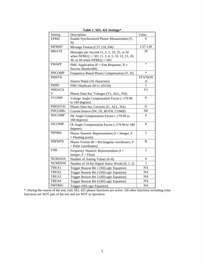
Other settings of SEL 421, shown in Table 1, remain the same throughout the test. (*) value denotes fields for the settings defined above. The ABB RES521 unit was used as a reference was set to filter #2, with frequency tracking on. The summary in Section 3 provides basic results for all four SEL setting combinations, followed by detailed test results and plots.
5
Table 1. SEL 421 Settings*
Setting Description Value EPMU Enable Synchronized Phasor Measurement (Y,
N) Y
MFRMT Message Format (C37.118, FM) C37.118 MRATE Messages per Second {1, 2, 5, 10, 25, or 50
when NFREQ := 50} {1, 2, 4, 5, 10, 12, 15, 20, 30, or 60 when NFREQ := 60}
30
PMAPP PMU Application (F = Fast Response, N = Narrow Bandwidth)
*
PHCOMP Frequency-Based Phasor Compensation (Y, N) * PMSTN
Station Name (16 characters) STATION
A PMID PMU Hardware ID (1–65534) 1 PHDATAV Phasor Data Set, Voltages (V1, ALL, NA)
V1
VCOMP Voltage Angle Compensation Factor (–179.99 to 180 degrees)
0
PHDATAI Phasor Data Set, Currents (I1, ALL, NA) I1 PHCURRc Current Source (IW, IX, BOTH, COMB) IW IWCOMP IW Angle Compensation Factor (–179.99 to
180 degrees) 0
IXCOMP IX Angle Compensation Factor (–179.99 to 180 degrees)
0
PHNRd Phasor Numeric Representation (I = Integer, F = Floating point)
I
PHFMTd Phasor Format (R = Rectangular coordinates, P = Polar coordinates)
R
FNR Frequency Numeric Representation (I = Integer, F = Float)
I
NUMANA Number of Analog Values (0–8) 0 NUMDSW Number of 16-bit Digital Status Words (0, 1, 2) 1 TREA1 Trigger Reason Bit 1 (SELogic Equation) NA TREA2 Trigger Reason Bit 2 (SELogic Equation) NA TREA3 Trigger Reason Bit 3 (SELogic Equation) NA TREA4 Trigger Reason Bit 4 (SELogic Equation) NA PMTRIG Trigger (SELogic Equation) NA
*: During the course of the test, only SEL 421 phasor functions are active. All other functions including relay functions are NOT part of the test and are NOT in operation.
6
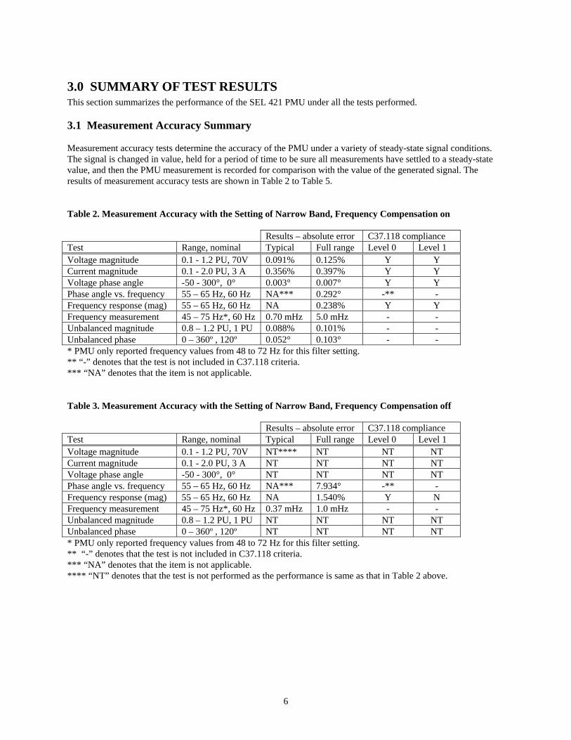
3.0 SUMMARY OF TEST RESULTS This section summarizes the performance of the SEL 421 PMU under all the tests performed. 3.1 Measurement Accuracy Summary Measurement accuracy tests determine the accuracy of the PMU under a variety of steady-state signal conditions. The signal is changed in value, held for a period of time to be sure all measurements have settled to a steady-state value, and then the PMU measurement is recorded for comparison with the value of the generated signal. The results of measurement accuracy tests are shown in Table 2 to Table 5. Table 2. Measurement Accuracy with the Setting of Narrow Band, Frequency Compensation on
Results – absolute error C37.118 compliance Test Range, nominal Typical Full range Level 0 Level 1 Voltage magnitude 0.1 - 1.2 PU, 70V 0.091% 0.125% Y Y Current magnitude 0.1 - 2.0 PU, 3 A 0.356% 0.397% Y Y Voltage phase angle -50 - 300°, 0° 0.003° 0.007° Y Y Phase angle vs. frequency 55 – 65 Hz, 60 Hz NA*** 0.292° -** - Frequency response (mag) 55 – 65 Hz, 60 Hz NA 0.238% Y Y Frequency measurement 45 – 75 Hz*, 60 Hz 0.70 mHz 5.0 mHz - - Unbalanced magnitude 0.8 – 1.2 PU, 1 PU 0.088% 0.101% - - Unbalanced phase 0 – 360º , 120º 0.052° 0.103° - - * PMU only reported frequency values from 48 to 72 Hz for this filter setting. ** “-” denotes that the test is not included in C37.118 criteria. *** “NA” denotes that the item is not applicable. Table 3. Measurement Accuracy with the Setting of Narrow Band, Frequency Compensation off
Results – absolute error C37.118 compliance Test Range, nominal Typical Full range Level 0 Level 1 Voltage magnitude 0.1 - 1.2 PU, 70V NT**** NT NT NT Current magnitude 0.1 - 2.0 PU, 3 A NT NT NT NT Voltage phase angle -50 - 300°, 0° NT NT NT NT Phase angle vs. frequency 55 – 65 Hz, 60 Hz NA*** 7.934° -** - Frequency response (mag) 55 – 65 Hz, 60 Hz NA 1.540% Y N Frequency measurement 45 – 75 Hz*, 60 Hz 0.37 mHz 1.0 mHz - - Unbalanced magnitude 0.8 – 1.2 PU, 1 PU NT NT NT NT Unbalanced phase 0 – 360º , 120º NT NT NT NT * PMU only reported frequency values from 48 to 72 Hz for this filter setting. ** “-” denotes that the test is not included in C37.118 criteria. *** “NA” denotes that the item is not applicable. **** “NT” denotes that the test is not performed as the performance is same as that in Table 2 above.
7
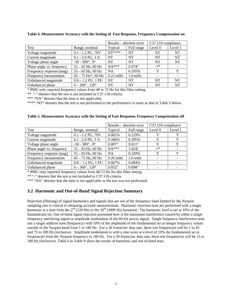
Table 4. Measurement Accuracy with the Setting of Fast Response, Frequency Compensation on
Results – absolute error C37.118 compliance Test Range, nominal Typical Full range Level 0 Level 1 Voltage magnitude 0.1 - 1.2 PU, 70V NT**** NT NT NT Current magnitude 0.1 - 2.0 PU, 3 A NT NT NT NT Voltage phase angle -50 - 300°, 0° NT NT NT NT Phase angle vs. frequency 55 – 65 Hz, 60 Hz NA*** 0.074° -** - Frequency response (mag) 55 – 65 Hz, 60 Hz NA 0.105% Y Y Frequency measurement 45 – 75 Hz*, 60 Hz 0.23 mHz 1.0 mHz - - Unbalanced magnitude 0.8 – 1.2 PU, 1 PU NT NT NT NT Unbalanced phase 0 – 360º , 120º NT NT NT NT * PMU only reported frequency values from 48 to 72 Hz for this filter setting. ** “-” denotes that the test is not included in C37.118 criteria. *** “NA” denotes that the item is not applicable. **** “NT” denotes that the test is not performed as the performance is same as that in Table 5 below. Table 5. Measurement Accuracy with the Setting of Fast Response, Frequency Compensation off
Results – absolute error C37.118 compliance Test Range, nominal Typical Full range Level 0 Level 1 Voltage magnitude 0.1 - 1.2 PU, 70V 0.081% 0.129% Y Y Current magnitude 0.1 - 2.0 PU, 3 A 0.346% 0.395% Y Y Voltage phase angle -50 - 300°, 0° 0.007° 0.011° Y Y Phase angle vs. frequency 55 – 65 Hz, 60 Hz NA*** 1.024° -** - Frequency response (mag) 55 – 65 Hz, 60 Hz NA 0.320% Y Y Frequency measurement 45 – 75 Hz, 60 Hz 0.20 mHz 1.0 mHz - - Unbalanced magnitude 0.8 – 1.2 PU, 1 PU 0.067% 0.084% - - Unbalanced phase 0 – 360º , 120º 0.052° 0.098° - - * PMU only reported frequency values from 48-72 Hz for this filter setting. ** “-” denotes that the test is not included in C37.118 criteria. *** “NA” denotes that the item is not applicable or the test was not performed. 3.2 Harmonic and Out-of-Band Signal Rejection Summary Rejection (filtering) of signal harmonics and signals that are out of the frequency band limited by the Nyquist sampling rate is critical to obtaining accurate measurements. Harmonic rejection tests are performed with a single harmonic at a time from the 2nd (120 Hz) to the 50th (3000 Hz) harmonic. The harmonic level is set at 10% of the fundamental set. Out-of-band signal rejection presented here is the maximum interference caused by either a single frequency interfering signal or amplitude modulation of the 60-Hz power signal. Single frequency interference tests use a single additive tone (frequency) with 10% of the amplitude of the fundamental set at integer frequency values outside of the Nyquist band from 1 to 180 Hz. For a 30 frame/sec data rate, these test frequencies will be 1 to 45 and 75 to 180 Hz (inclusive). Amplitude modulation is with a sine wave at a level of 10% the fundamental set at frequencies from the Nyquist frequency to 180 Hz. For a 30-frame/sec data rate, these test frequencies will be 15 to 180 Hz (inclusive). Table 6 to Table 9 show the results of harmonic and out-of-band tests.

8
Table 6. Harmonic and Out-of-Band Signal Rejection Summary with the Setting of Narrow Band, Frequency Compensation on
Results – absolute error C37.118 compliance
Test Range Typical Full range Level 0 Level 1 Harmonic rejection Harmonics 120-3000 Hz -36.26 dB -32.96 dB Y Y Out-of-band, single freq 1 - 180 Hz NA -26.06 dB Y Y Out-of-band, modulated 15 – 180 Hz NA -29.43 dB Y Y Table 7. Harmonic and Out-of-Band Signal Rejection Summary with the Setting of Narrow Band, Frequency Compensation off
Results – absolute error C37.118 compliance
Test Range Typical Full range Level 0 Level 1 Harmonic rejection Harmonics 120-3000 Hz -33.07 dB -27.11 dB Y Y Out-of-band, single freq 1 - 180 Hz NA -26.06 dB Y Y Out-of-band, modulated 15 – 180 Hz NA -29.44 dB Y Y Table 8. Harmonic and Out-of-Band Signal Rejection Summary with the Setting of Fast Response, Frequency Compensation on
Results – absolute error C37.118 compliance
Test Range Typical Full range Level 0 Level 1 Harmonic rejection Harmonics 120-3000 Hz -41.72 dB -26.16 dB Y Y Out-of-band, single freq 1 - 180 Hz NA -4.671 dB Y N Out-of-band, modulated 15 – 180 Hz NA -5.494 dB Y N Table 9. Harmonic and Out-of-Band Signal Rejection Summary with the Setting of Fast Response, Frequency Compensation off
Results – absolute error C37.118 compliance
Test Range Typical Full range Level 0 Level 1 Harmonic rejection Harmonics 120-3000 Hz -42.21 dB -26.28 dB Y Y Out-of-band, single freq 1 - 180 Hz NA -4.682 dB Y N Out-of-band, modulated 15 – 180 Hz NA -5.494 dB Y N 3.3 Modulated Signal Test Summary Modulated signals emulate power system equipment interactions and small signal oscillations. They provide a realistic way to assess the overall measurement capability and reject out-of-band interference. The frequency response of the demodulated signal determines phasor and frequency measurement pass bands. The pass band is given for 0.5 dB, a realistic measurement range, and 3 dB, a traditional bandwidth showing wide variation. Most PMUs exhibit a constant delay in the modulated signal, which gives a linear phase response. As summarized in Table 10 to Table 17, average and peak variation of delay is presented for easy measurement adjustment, and the measured phase angle response at 1 and 5 Hz is presented for easy comparison.

9
Table 10. Modulated Signal Test Summary in the Pass Band with the Setting of Narrow Band, Frequency Compensation on – Pass Band Test Test type Range Avg delay Delay
deviation
Phase angle, 1 Hz & 5 Hz
Amplitude modulation Passband, 3 dB 0.1 – 7.74 Hz 2.243 ms 10.60 ms 0° & 8° Passband, 0.5 dB 0.1 – 5.99 Hz 1.260 ms 6.148 ms 0° & 8° Phase modulation Passband, 3 dB 0.1 – 7.73 Hz 2.243 ms 10.60 ms 0° & 8° Passband, 0.5 dB 0.1 – 5.94 Hz 1.260 ms 6.148 ms 0° & 8° Frequency modulation Passband, 3 dB 0.1 – 3.18 Hz 83.61 ms 1.108 ms 30° & 160° Passband, 0.5 dB 0.1 – 1.49 Hz 83.40 ms 0.551 ms 30° & 160° Table 11. Modulated Signal Test Summary in the Pass Band with the Setting of Narrow Band, Frequency Compensation on – Out-of-Band Rejection Test Range 15 – 30 Hz 30 – 60 Hz 60 – 180 Hz Full range Amplitude modulation 15 – 180 Hz -29.432 dB -55.658 dB -54.101 dB -29.432 dB Phase modulation 15 – 180 Hz -29.430 dB -56.282 dB -31.679 dB -29.430 dB Frequency modulation 15 – 180 Hz -46.897 dB -80 dB -80 dB -46.897 dB Table 12. Modulated Signal Test Summary in the Pass Band with the Setting of Narrow Band, Frequency Compensation off – Pass Band Test Test type Range Avg delay Delay
deviation
Phase angle, 1 Hz & 5 Hz
Amplitude modulation Passband, 3 dB 0.1 – 7.74 Hz 2.243 ms 10.60 ms 0° & 8° Passband, 0.5 dB 0.1 – 5.99 Hz 1.260 ms 6.147 ms 0° & 8° Phase modulation Passband, 3 dB 0.1 – 7.73 Hz 2.243 ms 10.60 ms 0° & 8° Passband, 0.5 dB 0.1 – 5.94 Hz 1.260 ms 6.147 ms 0° & 8° Frequency modulation Passband, 3 dB 0.1 – 3.18 Hz 83.61 ms 1.108 ms 30° & 160° Passband, 0.5 dB 0.1 – 1.49 Hz 83.40 ms 0.551 ms 30° & 160° Table 13. Modulated Signal Test Summary in the Pass Band with the Setting of Narrow Band, Frequency Compensation off – Out-of-Band Rejection Test Range 15 – 30 Hz 30 – 60 Hz 60 – 180 Hz Full range Amplitude modulation 15 – 180 Hz -29.437 dB -55.561 dB -54.101 dB -29.437 dB Phase modulation 15 – 180 Hz -29.442 dB -54.368 dB -31.672 dB -29.442 dB Frequency modulation 15 – 180 Hz -46.897 dB -80 dB -80 dB -46.897 dB

10
Table 14. Modulated Signal Test Summary in the Pass Band with the Setting of Fast Response, Frequency Compensation on – Pass Band Test Test type Range Avg delay Delay
deviation
Phase angle, 1 Hz & 5 Hz
Amplitude modulation Passband, 3 dB 0.1 – 14.23 Hz 1.239 ms 4.912 ms 0° & 1.5° Passband, 0.5 dB 0.1 – 11.01 Hz 0.713 ms 3.075 ms 0° & 1.5° Phase modulation Passband, 3 dB 0.1 – 14.03 Hz 1.239 ms 4.912 ms 0° & 1.5° Passband, 0.5 dB 0.1 – 10.94 Hz 0.713 ms 3.075 ms 0° & 1.5° Frequency modulation Passband, 3 dB 0.1 – 3.18 Hz 83.46 ms 0.492 ms 30° & 145° Passband, 0.5 dB 0.1 – 1.58 Hz 83.40 ms 0.551 ms 30° & 145° Table 15. Modulated Signal Test Summary in the Pass Band with the Setting of Fast Response, Frequency Compensation on – Out-of-Band Rejection Test Range 15 – 30 Hz 30 – 60 Hz 60 – 180 Hz Full range Amplitude modulation 15 – 180 Hz -5.494 dB -34.400 dB -53.952 dB -5.494 dB Phase modulation 15 – 180 Hz -5.506 dB -16.310 dB -35.074 dB -7.367 dB Frequency modulation 15 – 180 Hz -21.709 dB -52.616 dB -80 dB -21.709 dB Table 16. Modulated Signal Test Summary in the Pass Band with the Setting of Fast Response, Frequency Compensation off – Pass Band Test Test type Range Avg delay Delay
deviation
Phase angle, 1 Hz & 5 Hz
Amplitude modulation Passband, 3 dB 0.1 – 14.23 Hz 1.239 ms 4.912 ms 0° & 1.5° Passband, 0.5 dB 0.1 – 11.01 Hz 0.713 ms 3.075 ms 0° & 1.5° Phase modulation Passband, 3 dB 0.1 – 14.22 Hz 1.274 ms 5.076 ms 0° & 1.5° Passband, 0.5 dB 0.1 – 10.96 Hz 0.744 ms 3.044 ms 0° & 1.5° Frequency modulation Passband, 3 dB 0.1 – 3.18 Hz 83.46 ms 0.492 ms 30° & 145° Passband, 0.5 dB 0.1 – 1.58 Hz 83.40 ms 0.551 ms 30° & 145° Table 17. Modulated Signal Test Summary in the Pass Band with the Setting of Fast Response, Frequency Compensation off – Put-of-Band Rejection Test Range 15 – 30 Hz 30 – 60 Hz 60 – 180 Hz Full range Amplitude modulation 15 – 180 Hz -5.494 dB -34.485 dB -53.952 dB -5.494 dB Phase modulation 15 – 180 Hz -5.506 dB -34.264 dB -31.798 dB -5.506 dB Frequency modulation 15 – 180 Hz -21.709 dB -52.616 dB -80 dB -21.709 dB 3.4 Step Test Summary Table 18 to Table 21 are the summary of step tests. Step tests start with a steady-state signal, which gives the PMU time to settle at an initial value, and then one of the parameters is stepped to a new value and held so the PMU can settle to the new value. These tests are actually performed in a repeated series with small delays in the actual step relative to measurement time. These repeated steps are then slipped back into a real time alignment to give a complete measurement curve. These tests illustrate the initial, transient, and final response in measurement time.

11
From this, PMU timing relative to absolute time, input signals, and other PMUs can be assessed. It also illustrates overshoot and settling in measurement. Steps in magnitude and phase angle illustrate phasor measurement response, and frequency steps illustrate frequency measurement response. Measurement synchronization and interference between measurements can be observed from these tests. Delay is defined as (“measured response” – “input step”) measured at the 50% point, average of positive & negative. This is somewhat arbitrary, but it corresponds to time centered in the measurement window. A negative delay means the response appears sooner than expected. Rise time is defined as the time interval from the response at 5% to 95%. Symmetry is the observation of ramp before and after mid point and between positive and negative steps. If symmetry is “N” (no), please refer to the detailed plots in the appendix for the particular cause. Table 18. Step Test Summary with the Setting of Narrow Band, Frequency Compensation on Test Step size, nominal value Delay Rise time Symmetry Voltage magnitude step 0.1 PU, 70-77V 4.891 ms 62.454 ms Y Voltage magnitude step 0.1 PU, 70-63V 4.903 ms 62.491 ms Y Current magnitude step 0.1 PU, 3-3.3A 4.996 ms 62.202 ms Y Current magnitude step 0.1 PU, 3-2.7A 4.838 ms 62.607 ms Y Phase angle step (voltage) 15º , 0-15º phase 4.894 ms 62.349 ms Y Phase angle step (voltage) 15º , 0-345º phase 4.872 ms 62.466 ms Y Frequency magnitude step 1 Hz, 60-61 Hz 86.141 ms 111.905 ms Y Frequency magnitude step 1 Hz, 60-59 Hz 86.174 ms 111.905 ms Y Table 19. Step Test Summary with the Setting of Narrow Band, Frequency Compensation off Test Step size, nominal value Delay Rise time Symmetry Voltage magnitude step 0.1 PU, 70-77V 4.867 ms 62.547 ms Y Voltage magnitude step 0.1 PU, 70-63V 4.903 ms 62.617 ms Y Current magnitude step 0.1 PU, 3-3.3A 4.926 ms 62.198 ms Y Current magnitude step 0.1 PU, 3-2.7A 4.917 ms 62.436 ms Y Phase angle step (voltage) 15º , 0-15º phase 4.879 ms 62.410 ms Y Phase angle step (voltage) 15º , 0-345º phase 4.880 ms 62.383 ms Y Frequency magnitude step 1 Hz, 60-61 Hz 86.141 ms 112.128 ms Y Frequency magnitude step 1 Hz, 60-59 Hz 86.174 ms 112.128 ms Y Table 20. Step Test Summary with the Setting of Fast Response, Frequency Compensation on Test Step size, nominal value Delay Rise time Symmetry Voltage magnitude step 0.1 PU, 70-77V 2.503 ms 33.743 ms Y Voltage magnitude step 0.1 PU, 70-63V 2.502 ms 33.828 ms Y Current magnitude step 0.1 PU, 3-3.3A 2.525 ms 33.870 ms Y Current magnitude step 0.1 PU, 3-2.7A 2.428 ms 33.609 ms Y Phase angle step (voltage) 15º , 0-15º phase 2.484 ms 33.684 ms Y Phase angle step (voltage) 15º , 0-345º phase 2.518 ms 33.693 ms Y Frequency magnitude step 1 Hz, 60-61 Hz 85.938 ms 98.049 ms Y Frequency magnitude step 1 Hz, 60-59 Hz 85.938 ms 98.049 ms Y
12
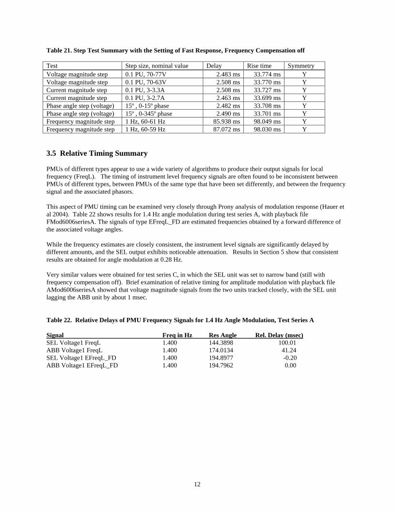
Table 21. Step Test Summary with the Setting of Fast Response, Frequency Compensation off Test Step size, nominal value Delay Rise time Symmetry Voltage magnitude step 0.1 PU, 70-77V 2.483 ms 33.774 ms Y Voltage magnitude step 0.1 PU, 70-63V 2.508 ms 33.770 ms Y Current magnitude step 0.1 PU, 3-3.3A 2.508 ms 33.727 ms Y Current magnitude step 0.1 PU, 3-2.7A 2.463 ms 33.699 ms Y Phase angle step (voltage) 15º , 0-15º phase 2.482 ms 33.708 ms Y Phase angle step (voltage) 15º , 0-345º phase 2.490 ms 33.701 ms Y Frequency magnitude step 1 Hz, 60-61 Hz 85.938 ms 98.049 ms Y Frequency magnitude step 1 Hz, 60-59 Hz 87.072 ms 98.030 ms Y 3.5 Relative Timing Summary PMUs of different types appear to use a wide variety of algorithms to produce their output signals for local frequency (FreqL). The timing of instrument level frequency signals are often found to be inconsistent between PMUs of different types, between PMUs of the same type that have been set differently, and between the frequency signal and the associated phasors. This aspect of PMU timing can be examined very closely through Prony analysis of modulation response (Hauer et al 2004). Table 22 shows results for 1.4 Hz angle modulation during test series A, with playback file FMod6006seriesA. The signals of type EFreqL_FD are estimated frequencies obtained by a forward difference of the associated voltage angles. While the frequency estimates are closely consistent, the instrument level signals are significantly delayed by different amounts, and the SEL output exhibits noticeable attenuation. Results in Section 5 show that consistent results are obtained for angle modulation at 0.28 Hz. Very similar values were obtained for test series C, in which the SEL unit was set to narrow band (still with frequency compensation off). Brief examination of relative timing for amplitude modulation with playback file AMod6006seriesA showed that voltage magnitude signals from the two units tracked closely, with the SEL unit lagging the ABB unit by about 1 msec. Table 22. Relative Delays of PMU Frequency Signals for 1.4 Hz Angle Modulation, Test Series A Signal Freq in Hz Res Angle Rel. Delay (msec) SEL Voltage1 FreqL 1.400 144.3898 100.01 ABB Voltage1 FreqL 1.400 174.0134 41.24 SEL Voltage1 EFreqL_FD 1.400 194.8977 -0.20 ABB Voltage1 EFreqL_FD 1.400 194.7962 0.00
13
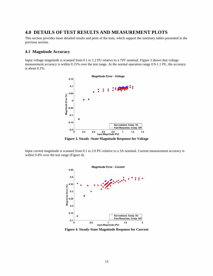
4.0 DETAILS OF TEST RESULTS AND MEASUREMENT PLOTS This section provides more detailed results and plots of the tests, which support the summary tables presented in the previous section. 4.1 Magnitude Accuracy Input voltage magnitude is scanned from 0.1 to 1.2 PU relative to a 70V nominal. Figure 3 shows that voltage measurement accuracy is within 0.15% over the test range. At the normal operation range 0.9-1.1 PU, the accuracy is about 0.1%.
Figure 3. Steady -State Magnitude Response for Voltage
Input current magnitude is scanned from 0.1 to 2.0 PU relative to a 3A nominal. Current measurement accuracy is within 0.4% over the test range (Figure 4).
Figure 4. Steady-State Magnitude Response for Current
14
4.2 Phase Angle Measurement
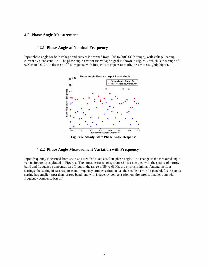
4.2.1 Phase Angle at Nominal Frequency Input phase angle for both voltage and current is scanned from -50° to 300° (350° range), with voltage leading current by a constant 30°. The phase angle error of the voltage signal is shown in Figure 5, which is in a range of -0.002° to 0.012°. In the case of fast response with frequency compensation off, the error is slightly higher.
Figure 5. Steady-State Phase Angle Response
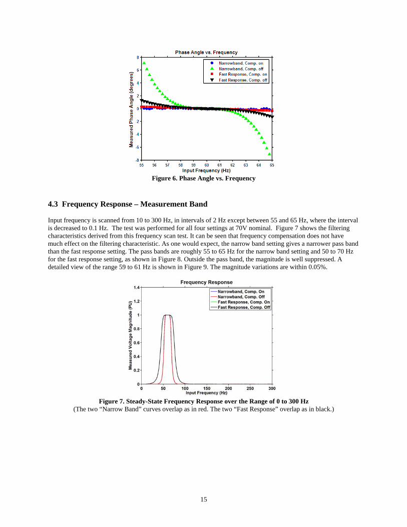
4.2.2 Phase Angle Measurement Variation with Frequency Input frequency is scanned from 55 to 65 Hz with a fixed absolute phase angle. The change in the measured angle versus frequency is plotted in Figure 6. The largest error ranging from ±8° is associated with the setting of narrow band and frequency compensation off, but in the range of 59 to 61 Hz, the error is minimal. Among the four settings, the setting of fast response and frequency compensation on has the smallest error. In general, fast response setting has smaller error than narrow band, and with frequency compensation on, the error is smaller than with frequency compensation off.
15
Figure 6. Phase Angle vs. Frequency
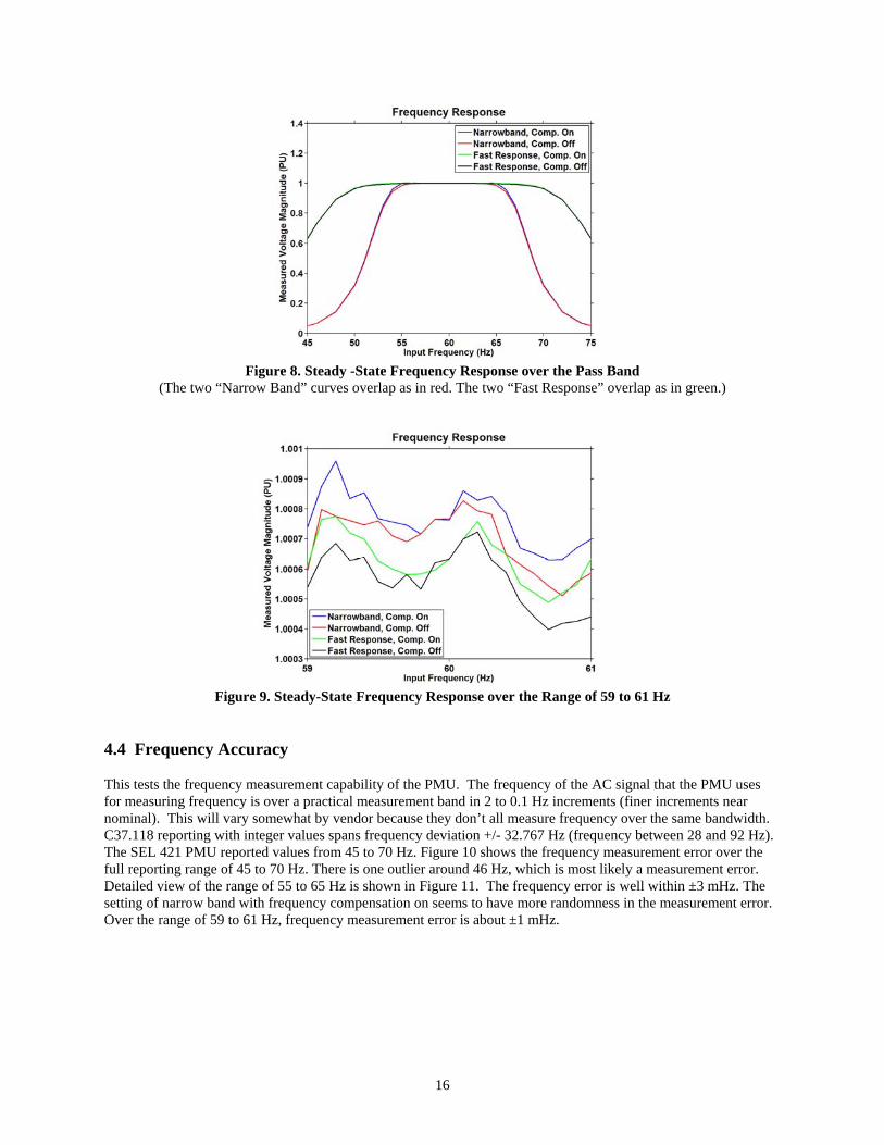
4.3 Frequency Response – Measurement Band Input frequency is scanned from 10 to 300 Hz, in intervals of 2 Hz except between 55 and 65 Hz, where the interval is decreased to 0.1 Hz. The test was performed for all four settings at 70V nominal. Figure 7 shows the filtering characteristics derived from this frequency scan test. It can be seen that frequency compensation does not have much effect on the filtering characteristic. As one would expect, the narrow band setting gives a narrower pass band than the fast response setting. The pass bands are roughly 55 to 65 Hz for the narrow band setting and 50 to 70 Hz for the fast response setting, as shown in Figure 8. Outside the pass band, the magnitude is well suppressed. A detailed view of the range 59 to 61 Hz is shown in Figure 9. The magnitude variations are within 0.05%.
Figure 7. Steady-State Frequency Response over the Range of 0 to 300 Hz
(The two “Narrow Band” curves overlap as in red. The two “Fast Response” overlap as in black.)
16
Figure 8. Steady -State Frequency Response over the Pass Band
(The two “Narrow Band” curves overlap as in red. The two “Fast Response” overlap as in green.)
Figure 9. Steady-State Frequency Response over the Range of 59 to 61 Hz
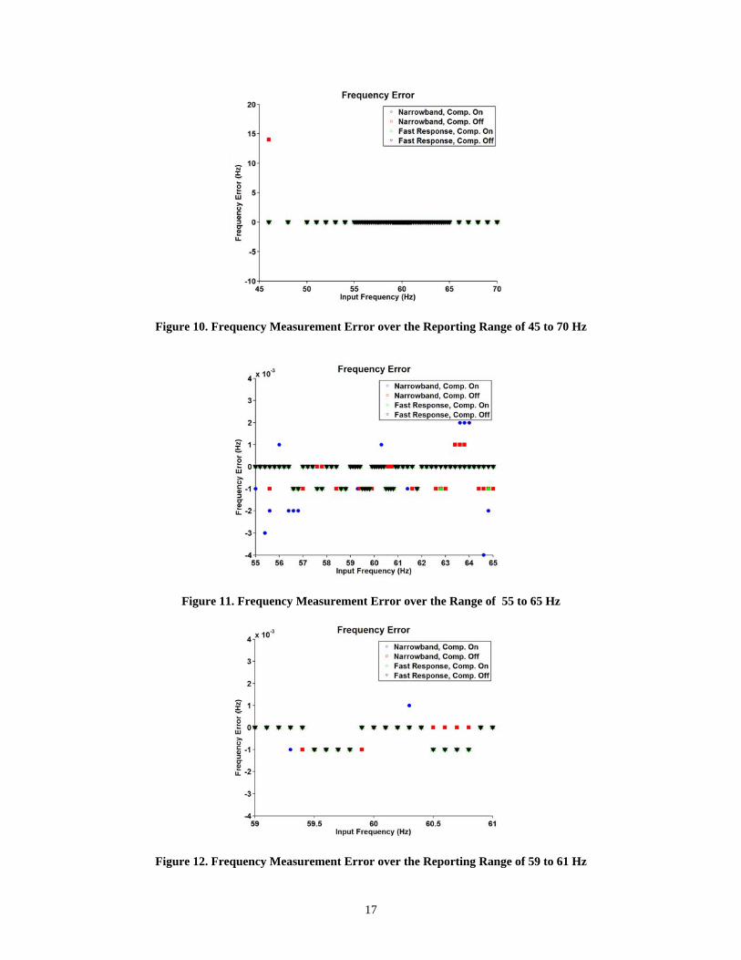
4.4 Frequency Accuracy This tests the frequency measurement capability of the PMU. The frequency of the AC signal that the PMU uses for measuring frequency is over a practical measurement band in 2 to 0.1 Hz increments (finer increments near nominal). This will vary somewhat by vendor because they don’t all measure frequency over the same bandwidth. C37.118 reporting with integer values spans frequency deviation +/- 32.767 Hz (frequency between 28 and 92 Hz). The SEL 421 PMU reported values from 45 to 70 Hz. Figure 10 shows the frequency measurement error over the full reporting range of 45 to 70 Hz. There is one outlier around 46 Hz, which is most likely a measurement error. Detailed view of the range of 55 to 65 Hz is shown in Figure 11. The frequency error is well within ±3 mHz. The setting of narrow band with frequency compensation on seems to have more randomness in the measurement error. Over the range of 59 to 61 Hz, frequency measurement error is about ±1 mHz.
17
Figure 10. Frequency Measurement Error over the Reporting Range of 45 to 70 Hz
Figure 11. Frequency Measurement Error over the Range of 55 to 65 Hz
Figure 12. Frequency Measurement Error over the Reporting Range of 59 to 61 Hz
(Hz)
(H
z)
(Hz)
18
4.5 Measurement of Unbalanced Signals
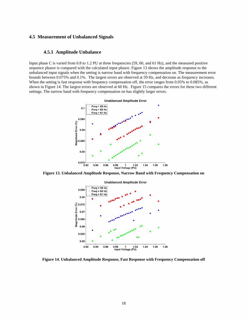
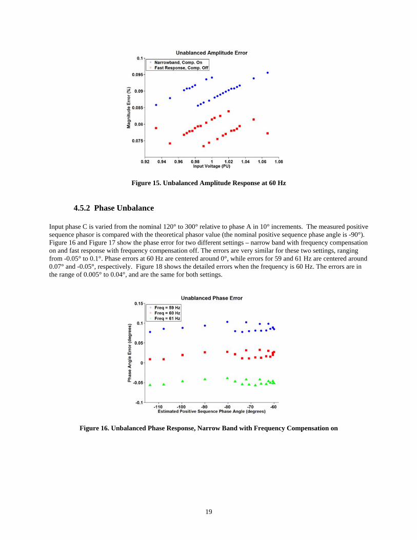
4.5.1 Amplitude Unbalance Input phase C is varied from 0.8 to 1.2 PU at three frequencies (59, 60, and 61 Hz), and the measured positive sequence phasor is compared with the calculated input phasor. Figure 13 shows the amplitude response to the unbalanced input signals when the setting is narrow band with frequency compensation on. The measurement error bounds between 0.075% and 0.1%. The largest errors are observed at 59 Hz, and decrease as frequency increases. When the setting is fast response with frequency compensation off, the error ranges from 0.05% to 0.085%, as shown in Figure 14. The largest errors are observed at 60 Hz. Figure 15 compares the errors for these two different settings. The narrow band with frequency compensation on has slightly larger errors.
Figure 13. Unbalanced Amplitude Response, Narrow Band with Frequency Compensation on
Figure 14. Unbalanced Amplitude Response, Fast Response with Frequency Compensation off
19
Figure 15. Unbalanced Amplitude Response at 60 Hz
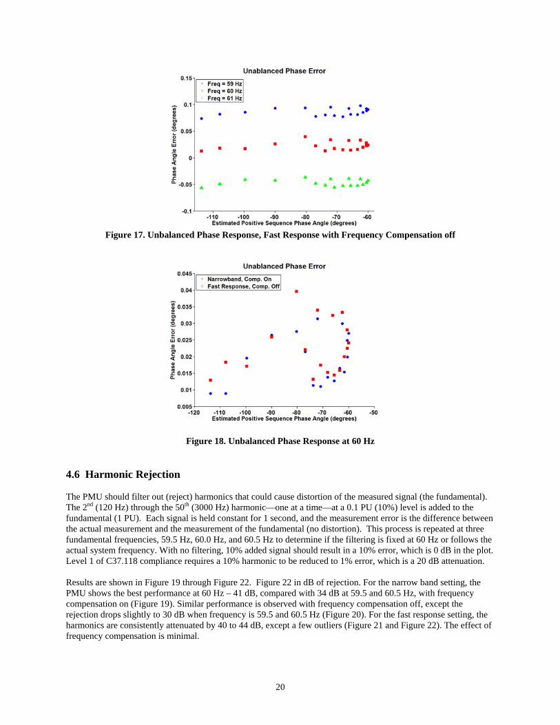
4.5.2 Phase Unbalance Input phase C is varied from the nominal 120° to 300° relative to phase A in 10° increments. The measured positive sequence phasor is compared with the theoretical phasor value (the nominal positive sequence phase angle is -90°). Figure 16 and Figure 17 show the phase error for two different settings – narrow band with frequency compensation on and fast response with frequency compensation off. The errors are very similar for these two settings, ranging from -0.05° to 0.1°. Phase errors at 60 Hz are centered around 0°, while errors for 59 and 61 Hz are centered around 0.07° and -0.05°, respectively. Figure 18 shows the detailed errors when the frequency is 60 Hz. The errors are in the range of 0.005° to 0.04°, and are the same for both settings.
Figure 16. Unbalanced Phase Response, Narrow Band with Frequency Compensation on
20
Figure 17. Unbalanced Phase Response, Fast Response with Frequency Compensation off
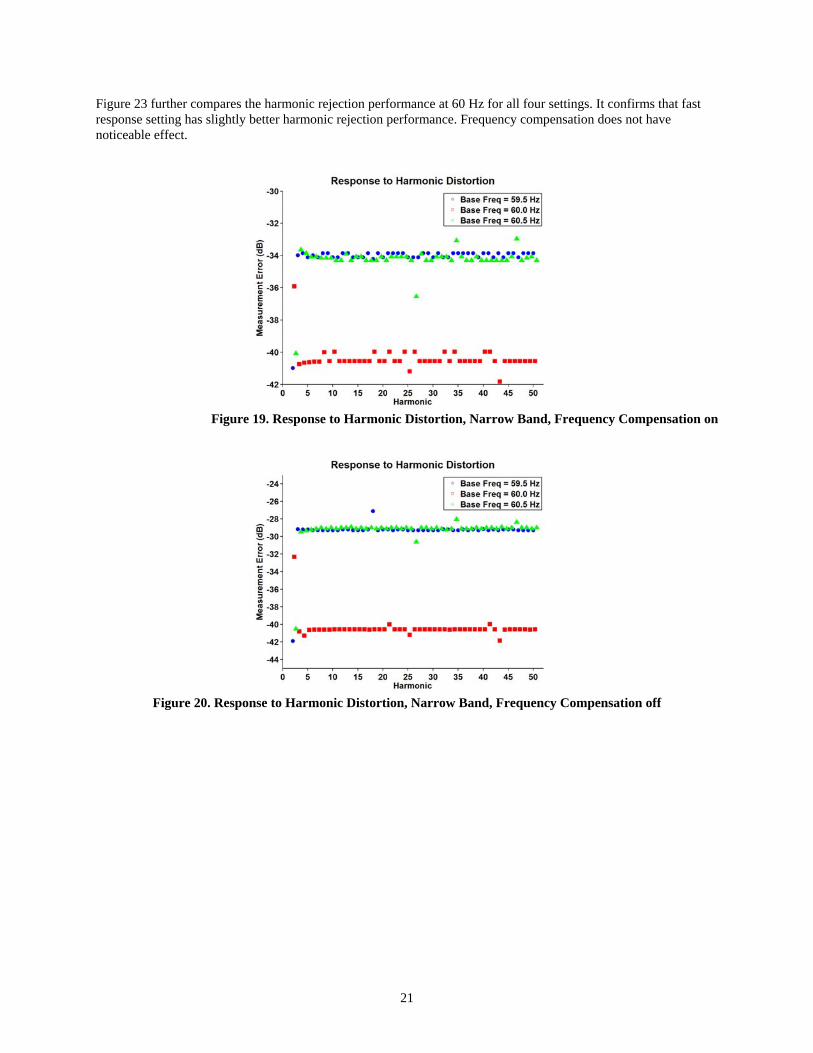
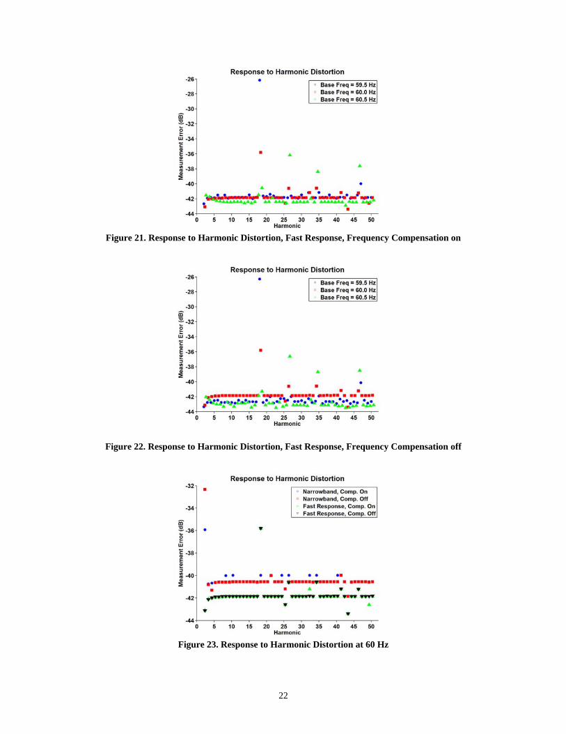
Figure 18. Unbalanced Phase Response at 60 Hz 4.6 Harmonic Rejection The PMU should filter out (reject) harmonics that could cause distortion of the measured signal (the fundamental). The 2nd (120 Hz) through the 50th (3000 Hz) harmonic—one at a time—at a 0.1 PU (10%) level is added to the fundamental (1 PU). Each signal is held constant for 1 second, and the measurement error is the difference between the actual measurement and the measurement of the fundamental (no distortion). This process is repeated at three fundamental frequencies, 59.5 Hz, 60.0 Hz, and 60.5 Hz to determine if the filtering is fixed at 60 Hz or follows the actual system frequency. With no filtering, 10% added signal should result in a 10% error, which is 0 dB in the plot. Level 1 of C37.118 compliance requires a 10% harmonic to be reduced to 1% error, which is a 20 dB attenuation. Results are shown in Figure 19 through Figure 22. Figure 22 in dB of rejection. For the narrow band setting, the PMU shows the best performance at 60 Hz – 41 dB, compared with 34 dB at 59.5 and 60.5 Hz, with frequency compensation on (Figure 19). Similar performance is observed with frequency compensation off, except the rejection drops slightly to 30 dB when frequency is 59.5 and 60.5 Hz (Figure 20). For the fast response setting, the harmonics are consistently attenuated by 40 to 44 dB, except a few outliers (Figure 21 and Figure 22). The effect of frequency compensation is minimal.
21
Figure 23 further compares the harmonic rejection performance at 60 Hz for all four settings. It confirms that fast response setting has slightly better harmonic rejection performance. Frequency compensation does not have noticeable effect.
Figure 19. Response to Harmonic Distortion, Narrow Band, Frequency Compensation on
Figure 20. Response to Harmonic Distortion, Narrow Band, Frequency Compensation off
22
Figure 21. Response to Harmonic Distortion, Fast Response, Frequency Compensation on
Figure 22. Response to Harmonic Distortion, Fast Response, Frequency Compensation off
Figure 23. Response to Harmonic Distortion at 60 Hz

23
4.7 Single Frequency Out-of-Band Rejection A single frequency sinusoid at 0.1 PU (10%) is added to the fundamental at 1 PU. The frequency of the sinusoid is varied from 1.5 to 179.5 Hz, in 1 Hz increments and held for 1 second at each frequency. Maximum error is calculated as the difference between the actual measurement and the fundamental set only over the 1 second dwell. Figure 24 shows the results of out-of-band rejection on a dB scale, where 0 dB represents no rejection. With the fast response setting, the amount of rejection approaches 5 dB at the Nyquist frequency. However, with the narrow band setting, the out-of-band distortion is suppressed at a level higher than 25 dB. There is minimal difference between test results with frequency compensation on and off.
Figure 24. Response to Single Out-of-Band Distortion
(All “Narrow Band” curves overlap as in red. All “Fast Response” overlap as in black.) 4.8 Amplitude Modulation
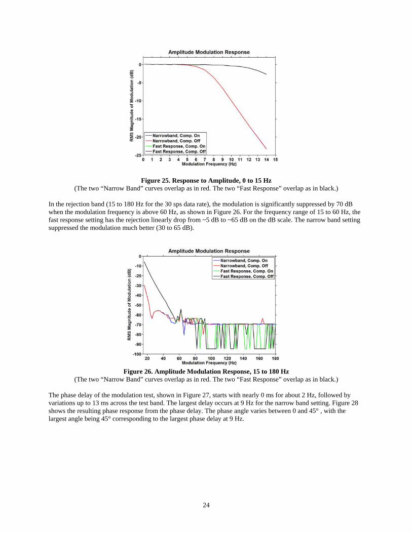
4.8.1 Amplitude Modulation with Nominal Frequency The test signal, with 70V nominal, is sinusoidal waveforms with 12% amplitude modulated with the amplitude modulation frequency ranging from 0.1 to 180 Hz. Figure 25 is the frequency response in the passband (0 to 15 Hz) for the 30 sps data rate (15 Hz Nyquist). The fast response setting has a fairly flat response in this frequency range, while the narrow band setting shows a considerably faster roll-off. Frequency compensation does not have noticeable effect.
24
Figure 25. Response to Amplitude, 0 to 15 Hz (The two “Narrow Band” curves overlap as in red. The two “Fast Response” overlap as in black.)
In the rejection band (15 to 180 Hz for the 30 sps data rate), the modulation is significantly suppressed by 70 dB when the modulation frequency is above 60 Hz, as shown in Figure 26. For the frequency range of 15 to 60 Hz, the fast response setting has the rejection linearly drop from ~5 dB to ~65 dB on the dB scale. The narrow band setting suppressed the modulation much better (30 to 65 dB).
Figure 26. Amplitude Modulation Response, 15 to 180 Hz
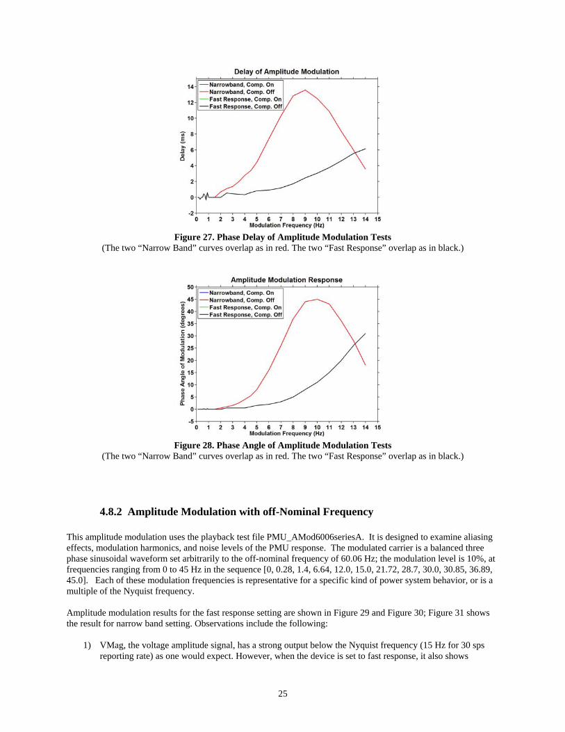
(The two “Narrow Band” curves overlap as in red. The two “Fast Response” overlap as in black.) The phase delay of the modulation test, shown in Figure 27, starts with nearly 0 ms for about 2 Hz, followed by variations up to 13 ms across the test band. The largest delay occurs at 9 Hz for the narrow band setting. Figure 28 shows the resulting phase response from the phase delay. The phase angle varies between 0 and 45° , with the largest angle being 45° corresponding to the largest phase delay at 9 Hz.
25
Figure 27. Phase Delay of Amplitude Modulation Tests
(The two “Narrow Band” curves overlap as in red. The two “Fast Response” overlap as in black.)
Figure 28. Phase Angle of Amplitude Modulation Tests
(The two “Narrow Band” curves overlap as in red. The two “Fast Response” overlap as in black.)
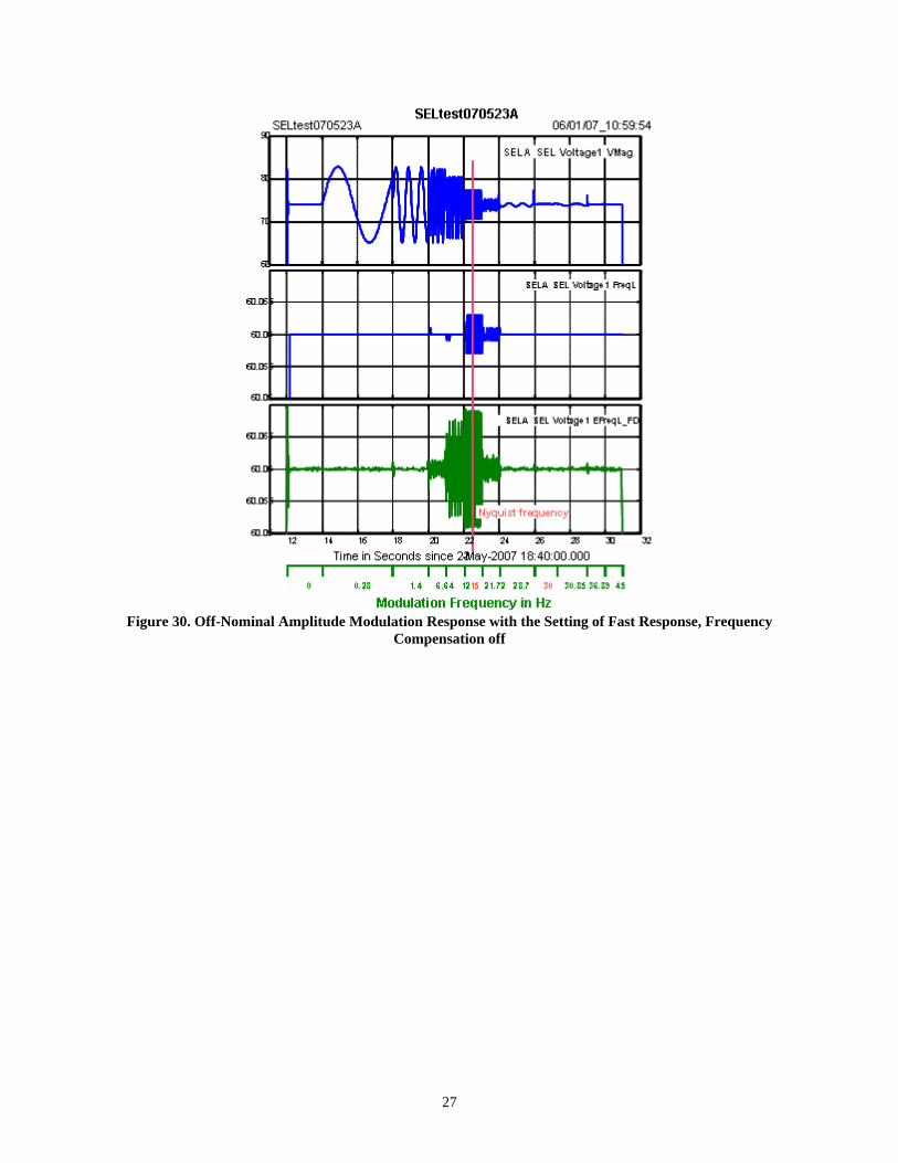
4.8.2 Amplitude Modulation with off-Nominal Frequency This amplitude modulation uses the playback test file PMU_AMod6006seriesA. It is designed to examine aliasing effects, modulation harmonics, and noise levels of the PMU response. The modulated carrier is a balanced three phase sinusoidal waveform set arbitrarily to the off-nominal frequency of 60.06 Hz; the modulation level is 10%, at frequencies ranging from 0 to 45 Hz in the sequence [0, 0.28, 1.4, 6.64, 12.0, 15.0, 21.72, 28.7, 30.0, 30.85, 36.89, 45.0]. Each of these modulation frequencies is representative for a specific kind of power system behavior, or is a multiple of the Nyquist frequency. Amplitude modulation results for the fast response setting are shown in Figure 29 and Figure 30; Figure 31 shows the result for narrow band setting. Observations include the following:
1) VMag, the voltage amplitude signal, has a strong output below the Nyquist frequency (15 Hz for 30 sps reporting rate) as one would expect. However, when the device is set to fast response, it also shows

26
significant response at some modulation frequencies that are above the Nyquist frequency. This indicates that system activity at such frequencies would be aliased to frequencies below 15 Hz. The narrow band filter attenuates the signals above the Nyquist frequency properly. This is consistent with the response shown in Figure 25.
2) FreqL, the frequency measurement signal, should hold at 60.06 Hz. However, with the fast response
setting, there are anomalous outputs in this signal for amplitude modulation at and above the Nyquist frequency. Again the narrow band setting improves the results and only shows minimal anomalies.
3) The frequency measurement is different from estimated frequency (labeled as “EFreqL_FD”) calculated
from phase angle measurements using the forward difference method. Results shown in Section 5 suggest that this is largely an effect of special filters used in the frequency measurement.
4) Frequency compensation does not have noticeable effect on the response. Discussions with the vendor
indicate that the frequency compensation logic presently used in the SEL 421 adjusts the PMU gain and phase in accordance with off nominal frequencies, but does not yet completely address the asymmetric filtering, which leads to anomalous outputs in the PMU frequency channel.
The anomalous outputs in the frequency channel seem characteristic of nearly all PMUs on the market, and they are not regarded as a serious problem. The user should be aware of them, however, especially in control applications where low level activity above 5 Hz or so may be of interest.
Figure 29. Off-Nominal Amplitude Modulation Response with the Setting of Fast Response, Frequency
Compensation on
27
Figure 30. Off-Nominal Amplitude Modulation Response with the Setting of Fast Response, Frequency
Compensation off
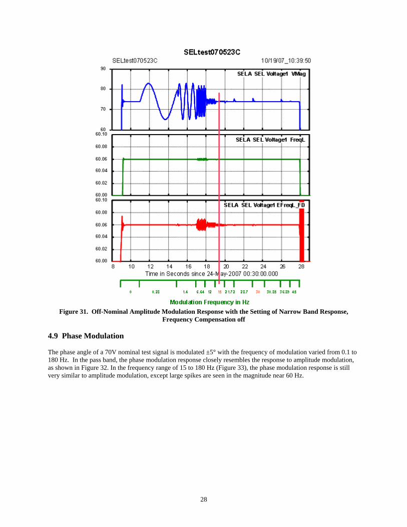
28
Figure 31. Off-Nominal Amplitude Modulation Response with the Setting of Narrow Band Response,
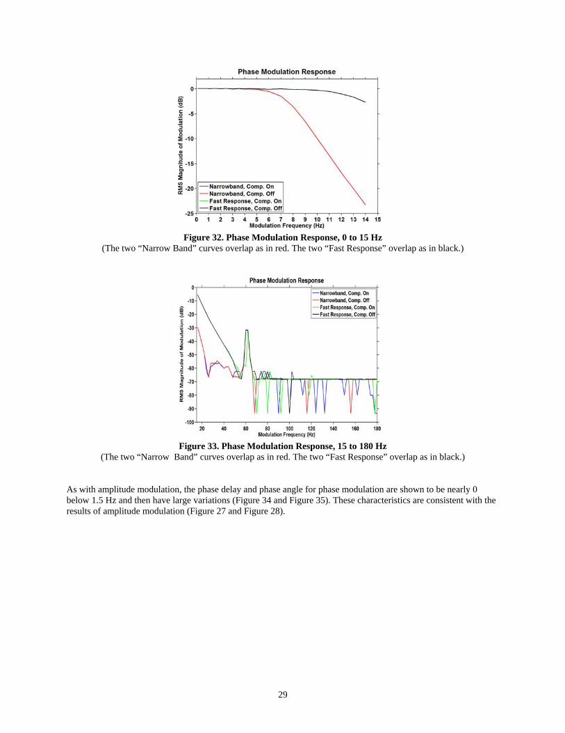
Frequency Compensation off 4.9 Phase Modulation The phase angle of a 70V nominal test signal is modulated ±5° with the frequency of modulation varied from 0.1 to 180 Hz. In the pass band, the phase modulation response closely resembles the response to amplitude modulation, as shown in Figure 32. In the frequency range of 15 to 180 Hz (Figure 33), the phase modulation response is still very similar to amplitude modulation, except large spikes are seen in the magnitude near 60 Hz.
29
Figure 32. Phase Modulation Response, 0 to 15 Hz
(The two “Narrow Band” curves overlap as in red. The two “Fast Response” overlap as in black.)
Figure 33. Phase Modulation Response, 15 to 180 Hz
(The two “Narrow Band” curves overlap as in red. The two “Fast Response” overlap as in black.)
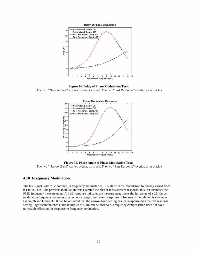
As with amplitude modulation, the phase delay and phase angle for phase modulation are shown to be nearly 0 below 1.5 Hz and then have large variations (Figure 34 and Figure 35). These characteristics are consistent with the results of amplitude modulation (Figure 27 and Figure 28).
30
Figure 34. Delay of Phase Modulation Tests (The two “Narrow Band” curves overlap as in red. The two “Fast Response” overlap as in black.)
Figure 35. Phase Angle of Phase Modulation Tests (The two “Narrow Band” curves overlap as in red. The two “Fast Response” overlap as in black.)
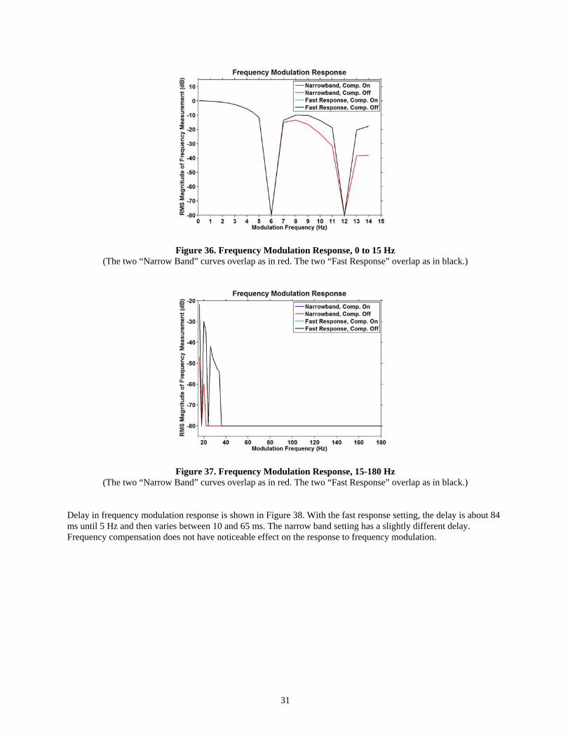
4.10 Frequency Modulation The test signal, with 70V nominal, is frequency modulated at ±0.5 Hz with the modulation frequency varied from 0.1 to 180 Hz. The previous modulation tests examine the phasor measurement response; this test examines the PMU frequency measurement. A 0 dB response indicates the measurement tracks the full range of ±0.5 Hz; as modulation frequency increases, the response range diminishes. Response to frequency modulation is shown in Figure 36 and Figure 37. It can be observed that the narrow band setting has less response than the fast response setting. Significant notches at the multiples of 6 Hz can be observed. Frequency compensation does not have noticeable effect on the response to frequency modulation.
31
Figure 36. Frequency Modulation Response, 0 to 15 Hz (The two “Narrow Band” curves overlap as in red. The two “Fast Response” overlap as in black.)
Figure 37. Frequency Modulation Response, 15-180 Hz (The two “Narrow Band” curves overlap as in red. The two “Fast Response” overlap as in black.)
Delay in frequency modulation response is shown in Figure 38. With the fast response setting, the delay is about 84 ms until 5 Hz and then varies between 10 and 65 ms. The narrow band setting has a slightly different delay. Frequency compensation does not have noticeable effect on the response to frequency modulation.
32
Figure 38. Delay of Frequency Modulation Test (The two “Narrow Band” curves overlap as in red. The two “Fast Response” overlap as in black.)
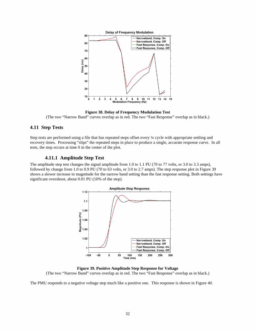
4.11 Step Tests Step tests are performed using a file that has repeated steps offset every ¼ cycle with appropriate settling and recovery times. Processing “slips” the repeated steps in place to produce a single, accurate response curve. In all tests, the step occurs at time 0 in the center of the plot.
4.11.1 Amplitude Step Test The amplitude step test changes the signal amplitude from 1.0 to 1.1 PU (70 to 77 volts, or 3.0 to 3.3 amps), followed by change from 1.0 to 0.9 PU (70 to 63 volts, or 3.0 to 2.7 amps). The step response plot in Figure 39 shows a slower increase in magnitude for the narrow band setting than the fast response setting. Both settings have significant overshoot, about 0.01 PU (10% of the step).
Figure 39. Positive Amplitude Step Response for Voltage (The two “Narrow Band” curves overlap as in red. The two “Fast Response” overlap as in black.)
The PMU responds to a negative voltage step much like a positive one. This response is shown in Figure 40.

33
Figure 40. Negative Amplitude Step Response for Voltage
(The two “Narrow Band” curves overlap as in red. The two “Fast Response” overlap as in black.) Responses to current steps (Figure 41 and Figure 42) have similar trends as the voltage tests. The narrow band setting has a slower response. Overshoot can be noticed in the plots.
Figure 41. Positive Amplitude Step Response for Current (The two “Narrow Band” curves overlap as in red. The two “Fast Response” overlap as in black.)
34
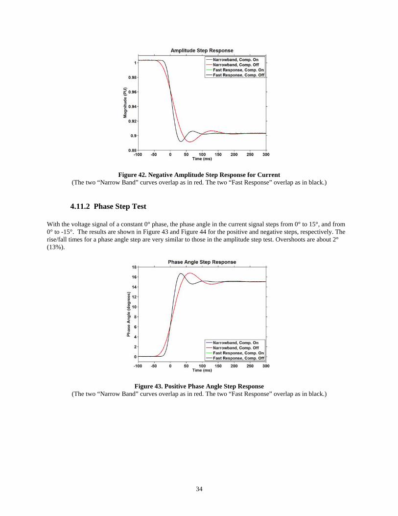
Figure 42. Negative Amplitude Step Response for Current (The two “Narrow Band” curves overlap as in red. The two “Fast Response” overlap as in black.)
4.11.2 Phase Step Test With the voltage signal of a constant 0° phase, the phase angle in the current signal steps from 0° to 15°, and from 0° to -15°. The results are shown in Figure 43 and Figure 44 for the positive and negative steps, respectively. The rise/fall times for a phase angle step are very similar to those in the amplitude step test. Overshoots are about 2° (13%).
Figure 43. Positive Phase Angle Step Response (The two “Narrow Band” curves overlap as in red. The two “Fast Response” overlap as in black.)
35
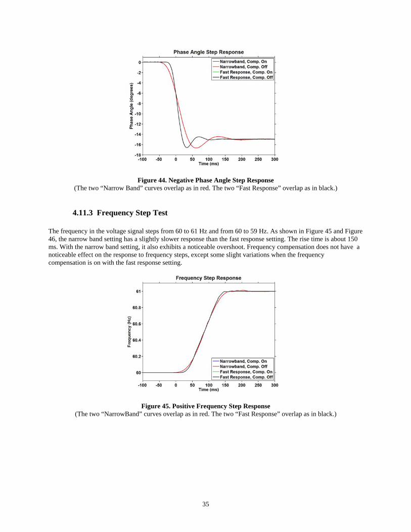
Figure 44. Negative Phase Angle Step Response (The two “Narrow Band” curves overlap as in red. The two “Fast Response” overlap as in black.)
4.11.3 Frequency Step Test The frequency in the voltage signal steps from 60 to 61 Hz and from 60 to 59 Hz. As shown in Figure 45 and Figure 46, the narrow band setting has a slightly slower response than the fast response setting. The rise time is about 150 ms. With the narrow band setting, it also exhibits a noticeable overshoot. Frequency compensation does not have a noticeable effect on the response to frequency steps, except some slight variations when the frequency compensation is on with the fast response setting.
Figure 45. Positive Frequency Step Response (The two “NarrowBand” curves overlap as in red. The two “Fast Response” overlap as in black.)

36
Figure 46. Negative Frequency Step Response (The two “Narrow Band” curves overlap as in red. The two “Fast Response” overlap as in black.)
37
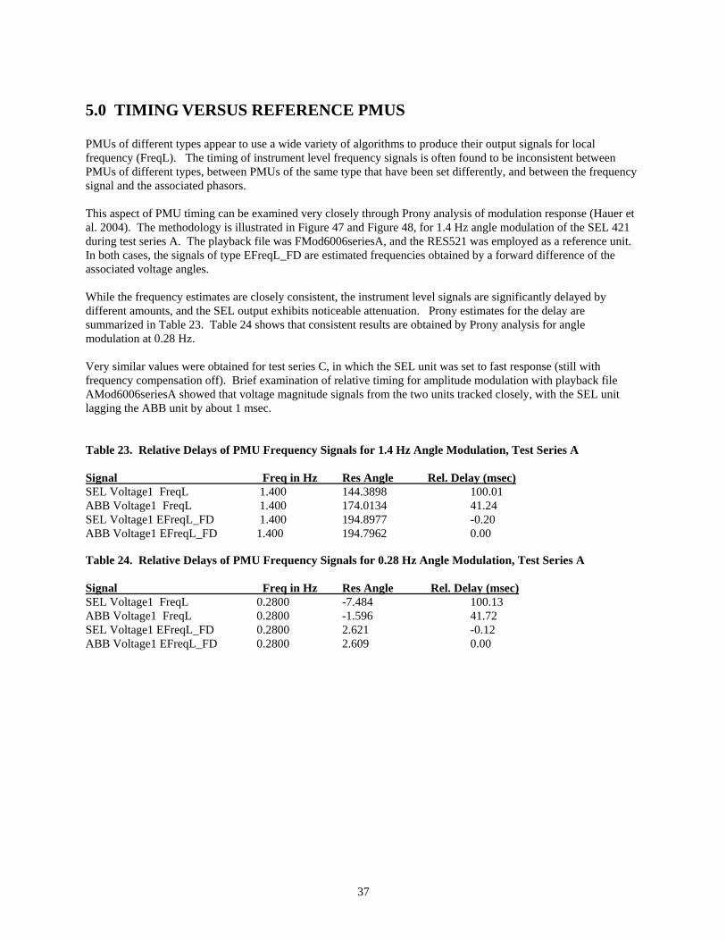
5.0 TIMING VERSUS REFERENCE PMUS PMUs of different types appear to use a wide variety of algorithms to produce their output signals for local frequency (FreqL). The timing of instrument level frequency signals is often found to be inconsistent between PMUs of different types, between PMUs of the same type that have been set differently, and between the frequency signal and the associated phasors. This aspect of PMU timing can be examined very closely through Prony analysis of modulation response (Hauer et al. 2004). The methodology is illustrated in Figure 47 and Figure 48, for 1.4 Hz angle modulation of the SEL 421 during test series A. The playback file was FMod6006seriesA, and the RES521 was employed as a reference unit. In both cases, the signals of type EFreqL_FD are estimated frequencies obtained by a forward difference of the associated voltage angles. While the frequency estimates are closely consistent, the instrument level signals are significantly delayed by different amounts, and the SEL output exhibits noticeable attenuation. Prony estimates for the delay are summarized in Table 23. Table 24 shows that consistent results are obtained by Prony analysis for angle modulation at 0.28 Hz. Very similar values were obtained for test series C, in which the SEL unit was set to fast response (still with frequency compensation off). Brief examination of relative timing for amplitude modulation with playback file AMod6006seriesA showed that voltage magnitude signals from the two units tracked closely, with the SEL unit lagging the ABB unit by about 1 msec. Table 23. Relative Delays of PMU Frequency Signals for 1.4 Hz Angle Modulation, Test Series A Signal Freq in Hz Res Angle Rel. Delay (msec) SEL Voltage1 FreqL 1.400 144.3898 100.01 ABB Voltage1 FreqL 1.400 174.0134 41.24 SEL Voltage1 EFreqL_FD 1.400 194.8977 -0.20 ABB Voltage1 EFreqL_FD 1.400 194.7962 0.00 Table 24. Relative Delays of PMU Frequency Signals for 0.28 Hz Angle Modulation, Test Series A Signal Freq in Hz Res Angle Rel. Delay (msec) SEL Voltage1 FreqL 0.2800 -7.484 100.13 ABB Voltage1 FreqL 0.2800 -1.596 41.72 SEL Voltage1 EFreqL_FD 0.2800 2.621 -0.12 ABB Voltage1 EFreqL_FD 0.2800 2.609 0.00

38
4.4 4.6 4.8 5 5.2 5.4 5.6-0.04
-0.03
-0.02
-0.01
0
0.01
0.02
0.03
0.04
Time Response
Time (sec)
SELtest070523A 07/06/071 1:43:31
SEL Voltage1 FreqL
ABB Voltage1 FreqL
SEL Voltage1 EFreqL_FD
ABB Voltage1 EFreqL_FD
4.4 4.6 4.8 5 5.2 5.4 5.6-0.04
-0.03
-0.02
-0.01
0
0.01
0.02
0.03
0.04
Time Response
Time (sec)
SELtest070523A 07/06/071 1:43:31
4.4 4.6 4.8 5 5.2 5.4 5.6-0.04
-0.03
-0.02
-0.01
0
0.01
0.02
0.03
0.04
Time Response
Time (sec)
SELtest070523A 07/06/071 1:43:31
SEL Voltage1 FreqL
ABB Voltage1 FreqL
SEL Voltage1 EFreqL_FD
ABB Voltage1 EFreqL_FD
Figure 47. PMU Frequency Signals for 1.4 Hz Amplitude Modulation, Test Series A
-0.015 -0.01 -0.005 0 0.005 0.01 0.015
-0.015
-0.01
-0.005
0
0.005
0.01
0.015
caseID=SELtest070523A casetime=07/06/071 1:43:31
Scaled Compass Plot for mode 1.400 Hz
SEL Voltage1 FreqL
ABB Voltage1 FreqL
SEL Voltage1 EFreqL_FDABB Voltage1 EFreqL_FD
-0.015 -0.01 -0.005 0 0.005 0.01 0.015
-0.015
-0.01
-0.005
0
0.005
0.01
0.015
caseID=SELtest070523A casetime=07/06/071 1:43:31
Scaled Compass Plot for mode 1.400 Hz
SEL Voltage1 FreqL
ABB Voltage1 FreqL
SEL Voltage1 EFreqL_FDABB Voltage1 EFreqL_FD
Figure 48. Relative Phase of PMU Frequency Signals for 1.4 Hz Amplitude Modulation, Test Series A
39
6.0 REFERENCES Bonneville Power Administration. 1999. Wide Area Measurements for Real-Time Control and Operation of Large Electric Power Systems – Evaluation And Demonstration Of Technology For The New Power System. Prepared for U.S. Department of Energy, January 1999. This report and associated attachments are available on compact disk.
Hauer, J. 1996. “Validation of Phasor Calculation in the Macrodyne PMU for California-Oregon Transmission Project Tests of March 1993.” IEEE Trans. Power Delivery, vol. 11, pp. 1224-1231, July 1996.
Hauer, J.F., K.E. Martin and H. Lee. 2004. “Evaluating the Dynamic Performance of Phasor Measurement Units: Experience in the Western Power System,. WECC Disturbance Monitoring Work Group, June 15, 2004.
Hauer, J. 2001. Use of Synchronized Phasor Measurements to Correct Timestamp and Filter Effects in Monitor Records Collected from Analog Instrumentation: Applied to Records of June 7, 2000 and August 10, 1996. Working Note for the WECC Modeling & Validation Work Group, December 21, 2001
Hauer, J., W.A. Mittelstadt, K.D. Martin J.W. Burns, and H. Lee. 2007. Direct Analysis of Wide Area Dynamics. Prepared in association with the Disturbance Monitoring Work Group of the Western Electricity Coordinating Council. The Electric Power Engineering Handbook, edition 2, L. L. Grigsby ed., CRC Press, 2007.
IEEE Standard for Synchrophasors for Power Systems, IEEE Standard C37.118-2005, March 2006.
Martin, K.E. 1992. “Phasor Measurement System Test,” 1992 BPA Engineering Symposium, Vol. 2, pp. 689-704, Portland, Oregon.
Martin, K.E. 2004. WECC Disturbance/Performance Monitor Equipment: Proposed Standards for WECC Certification and Reimbursement. Draft report of the WECC Disturbance Monitoring Work Group, March 17, 2004.
Phadke, A.G., J.S. Thorp, and M.G. Adamiak. 1983. “A New Measurement Technique for Tracking Voltage Phasors, Local System Frequency, and Rate of Change of Frequency.” IEEE Transactions on Power Apparatus and Systems, vol. PAS-102, no. 5, pp. 1025-1038, May 1983.
40
APPENDIX A
WECC Requirements for Monitoring Equipment
41
APPENDIX A: WECC Requirements for Monitoring Equipment In 200,1 the WECC approved its Dynamic Performance and Disturbance Monitoring Plan to address North American Electric Reliability Corporation (NERC) Planning Standard I. F., System Adequacy and Security - Disturbance Monitoring. Within this plan, the WECC established a reimbursement program to assist member utilities with the cost of equipment and maintenance associated with dynamic disturbance monitors at selected system locations. A monitor shall be judged as meeting basic WECC performance requirements if it satisfies the following technical criteria (Martin 2004): • Frequency response of overall data acquisition:
– is -3 dB or greater at 5 Hz. – does not exceed -40 dB at frequencies above the Nyquist frequency ( a limit of –60 dB is preferred) – does not exceed -60 dB at frequencies that are harmonics of the actual power system operating
frequency (for design purposes, assume all frequencies in the range of 59 Hz to 61 Hz) – does not produce excessive ringing in records for step disturbances
• Data sampling rate: – Overall frequency response requirements imply a minimum sample rate that is four to five times the –3
dB bandwidth of overall data acquisition – For compatibility with other monitors, the sample rate should be an integer multiple of 20 or 30
samples per second (sps). A multiple of 30 sps is preferred.
• Numerical resolution and dynamic range: – Resolution of the analog-to-digital (A/D) conversion process must be 16 bits or higher. – Scaling of signals entering the A/D conversion should assure that 12 to 14 bits are actively used to
represent them. Signals for which this scaling may overload the A/D during large transients may be recorded on two channels, in which one has less resolution but a greater dynamic range.
• Measurement noise must be within the normal limits of modern instrument technology. Noise levels for frequency transducers that are based upon zero-crossing logic tend to be unacceptable.
• Documentation for the data acquisition process: – must be sufficiently detailed that overall quality of the acquisition system can be assessed – must be sufficiently detailed that acquired records can be compensated for attenuation and phase lags
introduced by the acquisition system
• The monitor or monitor system stores data continuously and retains the last 240 hours (10 days) at all times without operator intervention. A monitor that automatically erases the oldest file and stores the newest file will meet this criterion if the buffer area is 10 days or more. If the monitor requires an operator to remove old data to prevent storage overflow, a 60-day buffer is required to accommodate typical practices with monitor systems.
• The monitor is able to typically store event data files for 60 days without operator intervention. Because events are inherently unpredictable, this is only a ‘typical’ value based on operating experience. If the monitor stores continuous data, it does not have to store events.
• The monitor demonstrates synchronization to Universal Time (UTC) to a 100μs level or better. Synchronization to GPS-based timing with suitable technique is preferred. Other approaches may be acceptable.
• Data access is by network, leased line, or dial-up with software for transfer, storage, and data archiving.
• Data formats are well defined and reasonable. Preferred formats for real-time data transfer are those equivalent to or meeting IEEE standards IEEE1344 or PC37.118 or the PDCstream format for concentrator
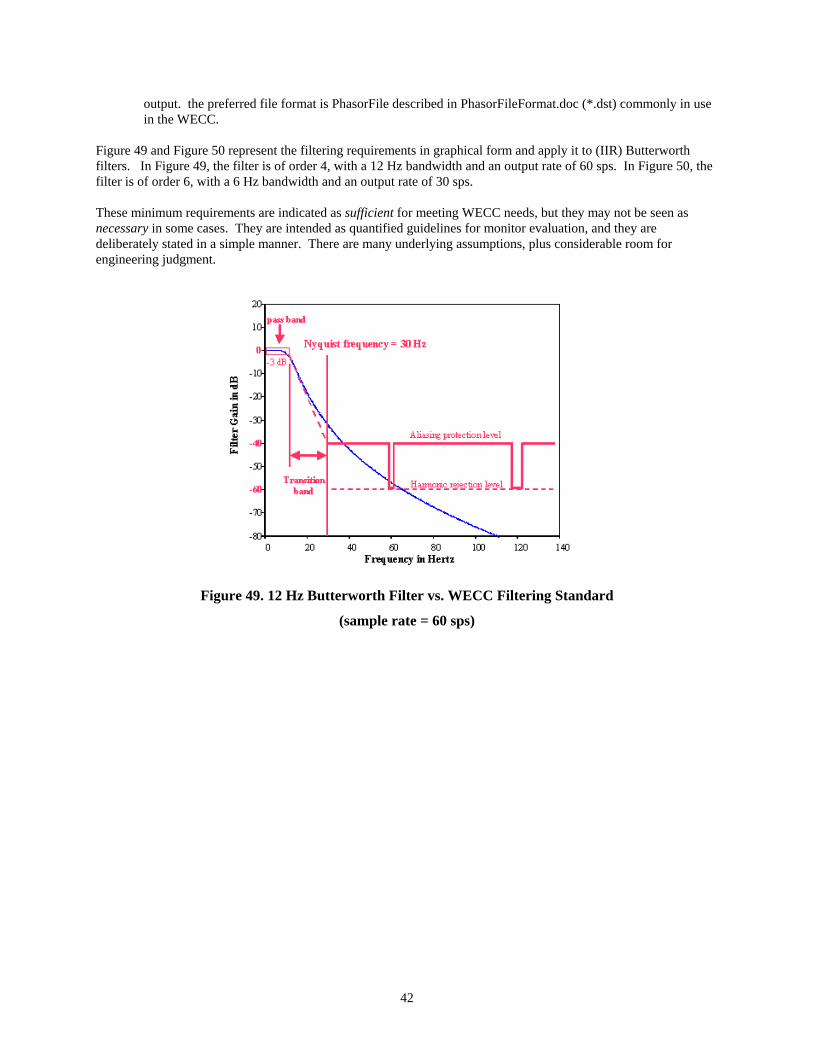
42
output. the preferred file format is PhasorFile described in PhasorFileFormat.doc (*.dst) commonly in use in the WECC.
Figure 49 and Figure 50 represent the filtering requirements in graphical form and apply it to (IIR) Butterworth filters. In Figure 49, the filter is of order 4, with a 12 Hz bandwidth and an output rate of 60 sps. In Figure 50, the filter is of order 6, with a 6 Hz bandwidth and an output rate of 30 sps. These minimum requirements are indicated as sufficient for meeting WECC needs, but they may not be seen as necessary in some cases. They are intended as quantified guidelines for monitor evaluation, and they are deliberately stated in a simple manner. There are many underlying assumptions, plus considerable room for engineering judgment.
Figure 49. 12 Hz Butterworth Filter vs. WECC Filtering Standard
(sample rate = 60 sps)
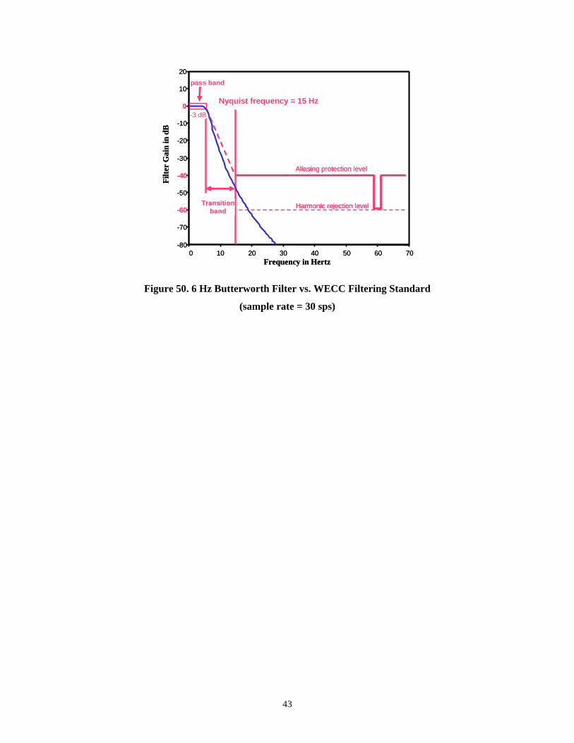
43
0 10 20 30 40 50 60 70-80
-70
-60
-50
-40
-30
-20
-10
0
10
20
Harmonic rejection level
Nyquist frequency = 15 Hz
Transitionband
pass band
Aliasing protection level
Frequency in Hertz
Filte
r G
ain
in d
B
-3 dB
0 10 20 30 40 50 60 70-80
-70
-60
-50
-40
-30
-20
-10
0
10
20
Harmonic rejection level
Nyquist frequency = 15 Hz
Transitionband
pass band
Aliasing protection level
Frequency in Hertz
Filte
r G
ain
in d
B
-3 dB
Figure 50. 6 Hz Butterworth Filter vs. WECC Filtering Standard
(sample rate = 30 sps)

44
APPENDIX B
IEEE Guidelines for PMU Performance
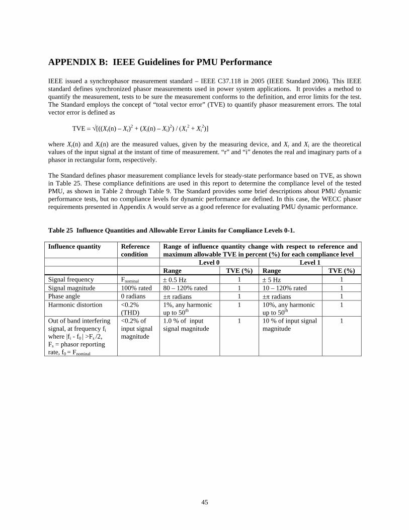
45
APPENDIX B: IEEE Guidelines for PMU Performance IEEE issued a synchrophasor measurement standard – IEEE C37.118 in 2005 (IEEE Standard 2006). This IEEE standard defines synchronized phasor measurements used in power system applications. It provides a method to quantify the measurement, tests to be sure the measurement conforms to the definition, and error limits for the test. The Standard employs the concept of “total vector error” (TVE) to quantify phasor measurement errors. The total vector error is defined as TVE = √[((Xr(n) – Xr)2 + (Xi(n) – Xi)2) / (Xr
2 + Xi2)]
where Xr(n) and Xi(n) are the measured values, given by the measuring device, and Xr and Xi are the theoretical values of the input signal at the instant of time of measurement. “r” and “i” denotes the real and imaginary parts of a phasor in rectangular form, respectively. The Standard defines phasor measurement compliance levels for steady-state performance based on TVE, as shown in Table 25. These compliance definitions are used in this report to determine the compliance level of the tested PMU, as shown in Table 2 through Table 9. The Standard provides some brief descriptions about PMU dynamic performance tests, but no compliance levels for dynamic performance are defined. In this case, the WECC phasor requirements presented in Appendix A would serve as a good reference for evaluating PMU dynamic performance. Table 25 Influence Quantities and Allowable Error Limits for Compliance Levels 0-1. Influence quantity Reference
condition Range of influence quantity change with respect to reference and maximum allowable TVE in percent (%) for each compliance level
Level 0 Level 1 Range TVE (%) Range TVE (%) Signal frequency Fnominal ± 0.5 Hz 1 ± 5 Hz 1 Signal magnitude 100% rated 80 – 120% rated 1 10 – 120% rated 1 Phase angle 0 radians ±π radians 1 ±π radians 1 Harmonic distortion <0.2%
(THD) 1%, any harmonic up to 50th
1 10%, any harmonic up to 50th
1
Out of band interfering signal, at frequency fi where |fi - f0 | >Fs /2, Fs = phasor reporting rate, f0 = Fnominal
<0.2% of input signal magnitude
1.0 % of input signal magnitude
1
10 % of input signal magnitude
1
46
APPENDIX C
PMU Types Used in Performance Comparisons

47
APPENDIX C: PMU Types Used in Performance Comparisons New or revised PMU types are often tested in tandem with other PMU types (or PMU models) that are well understood, and in common use. This provides cross calibration data that may be needed to refine the consistency of measurements from the different instrument types. Also, by comparing results from the reference units against those of earlier tests, one can readily establish that the present tests are being performed correctly. At present the following PMU types and models are used as reference units for performance comparisons:
• Macrodyne 1690M
• ABB RES521, usually with filter #2 and frequency tracking on
• MATLAB model PMU_Box1&4X30 for the 1690M These are usually operated with an output rate of 30 sps, but with some exceptions for exploratory purposes. C.1 General Characteristics of the Macrodyne 1690M The Macrodyne 1690M is a realization of the basic algorithm presented in Phadke et al. (1983), but with additional filtering to reduce the exposure to out-of-band signals. Primary filtering consists of a one cycle “boxcar” in series with a four cycle boxcar, with response functions as shown in Figure 51 and Figure 52. Figure 52 through Figure 55, plus other comparisons in Hauer et al (2004), show that the associated model PMU_Box1&4X30 replicates measured response of the 1690M very closely. Figure 53 shows that filtering for the 1690M falls well short of the WECC standard. Effects of this are illustrated in Figure 54, which shows substantial PMU outputs for signal components above the Nyquist frequency. Such outputs are necessarily “aliased” to lower frequencies, and are easily mistaken for types of system behavior other than what they actually represent.
0 5 10 15 20 25 30 35 40 450
0.1
0.2
0.3
0.4
0.5
0.6
0.7
0.8
0.9
1
1-cycle boxcar
4-cycle boxcar
Figure 51. Two Stage Fourier Filter Approximating that of the Macrodyne 1690M PMU
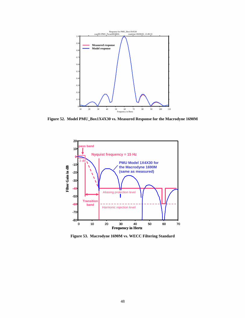
48
10 20 30 40 50 60 70 80 90 100 1100
0.1
0.2
0.3
0.4
0.5
0.6
0.7
0.8
0.9
1.0
Frequency in Hertz
Response for PMU_Box1X4X30caseID=PMU_Fscan000480A casetime=08/08/02_13:49:33
Measured responseModel response
10 20 30 40 50 60 70 80 90 100 1100
0.1
0.2
0.3
0.4
0.5
0.6
0.7
0.8
0.9
1.0
Frequency in Hertz
Response for PMU_Box1X4X30caseID=PMU_Fscan000480A casetime=08/08/02_13:49:33
Measured responseModel response
Figure 52. Model PMU_Box1X4X30 vs. Measured Response for the Macrodyne 1690M
0 10 20 30 40 50 60 70-80
-70
-60
-50
-40
-30
-20
-10
0
10
20
Nyquist frequency = 15 Hz
Transitionband
pass band
Frequency in Hertz
Filte
r G
ain
in d
B
-3 dB
Harmonic rejection level
PMU Model 1X4X30 for the Macrodyne 1690M(same as measured)
Aliasing protection level
-3 dB
0 10 20 30 40 50 60 70-80
-70
-60
-50
-40
-30
-20
-10
0
10
20
Nyquist frequency = 15 Hz
Transitionband
pass band
Frequency in Hertz
Filte
r G
ain
in d
B
-3 dB
Harmonic rejection level
PMU Model 1X4X30 for the Macrodyne 1690M(same as measured)
Aliasing protection level
-3 dB-3 dB
Figure 53. Macrodyne 1690M vs. WECC Filtering Standard

49
14 16 18 20 22 24 26 28 30 0.12
0.13
0.14
0.15
0.16
0.17
0.18
0.19
0.20
MACD Macrodyne Voltage VMagcaseID=ABBT_Mod6006MseriesB0207191744 casetime=08/07/02_08:00:14
Time in Seconds
0 0.28 1.4 6.64 12 21.72 36.89 45 0 0.28 1.4 6.64 12 21.72 36.89 45
0 0.28 1.4 6.64 12 15 8.28 0.85 6.89 15 01.30 0 0.28 1.4 6.64 12 15 8.28 0.85 6.89 15 0
PMU output frequency (Hz)
28.70 30.8530150 0.28 1.4 6.64 12 21.72 36.89 45 input modulation frequency (Hz)
Figure 54. Modulation of Balanced 60.06 Hz Carrier, Macrodyne 1690M Test file PMU_AMod6006seriesA
20 22 24 26 28 30 32 34 3622
23
24
25
26
27
28
29
30
PMU Type A VMag LcaseID=MANTA_Mod6006MseriesB casetime=06/26/02_11:14:22
Time in Seconds
0 0.28 1.4 6.64 12 15 21.72 28.72 30.85 36.89 4530
input modulation frequency (Hz)
0 0.28 1.4 6.64 12 15 8.28 1.28 0.85 6.89 150
PMU output frequency (Hz)
Nyquist Frequency=15 Hz
20 22 24 26 28 30 32 34 3622
23
24
25
26
27
28
29
30
PMU Type A VMag LcaseID=MANTA_Mod6006MseriesB casetime=06/26/02_11:14:22
Time in Seconds
0 0.28 1.4 6.64 12 15 21.72 28.72 30.85 36.89 4530
input modulation frequency (Hz)
0 0.28 1.4 6.64 12 15 21.72 28.72 30.85 36.89 45300 0.28 1.4 6.64 12 15 21.72 28.72 30.85 36.89 4530
input modulation frequency (Hz)
0 0.28 1.4 6.64 12 15 8.28 1.28 0.85 6.89 150
PMU output frequency (Hz)
0 0.28 1.4 6.64 12 15 8.28 1.28 0.85 6.89 150
PMU output frequency (Hz)
Nyquist Frequency=15 Hz
20 22 24 26 28 30 32 34 3622
23
24
25
26
27
28
29
30
PMU Type A VMag LcaseID=MANTA_Mod6006MseriesB casetime=06/26/02_11:14:22
Time in Seconds
0 0.28 1.4 6.64 12 15 21.72 28.72 30.85 36.89 45300 0.28 1.4 6.64 12 15 21.72 28.72 30.85 36.89 4530
input modulation frequency (Hz)
0 0.28 1.4 6.64 12 15 21.72 28.72 30.85 36.89 45300 0.28 1.4 6.64 12 15 21.72 28.72 30.85 36.89 4530
input modulation frequency (Hz)
0 0.28 1.4 6.64 12 15 8.28 1.28 0.85 6.89 150
PMU output frequency (Hz)
0 0.28 1.4 6.64 12 15 8.28 1.28 0.85 6.89 150
PMU output frequency (Hz)
Nyquist Frequency=15 Hz
0 0.28 1.4 6.64 12 15 8.28 1.28 0.85 6.89 150
PMU output frequency (Hz)
Nyquist Frequency=15 Hz
Figure 55. Modulation of Balanced 60.06 Hz Carrier, PMU Model PMU_Box1&4X30
Test file PMU_AMod6006seriesA
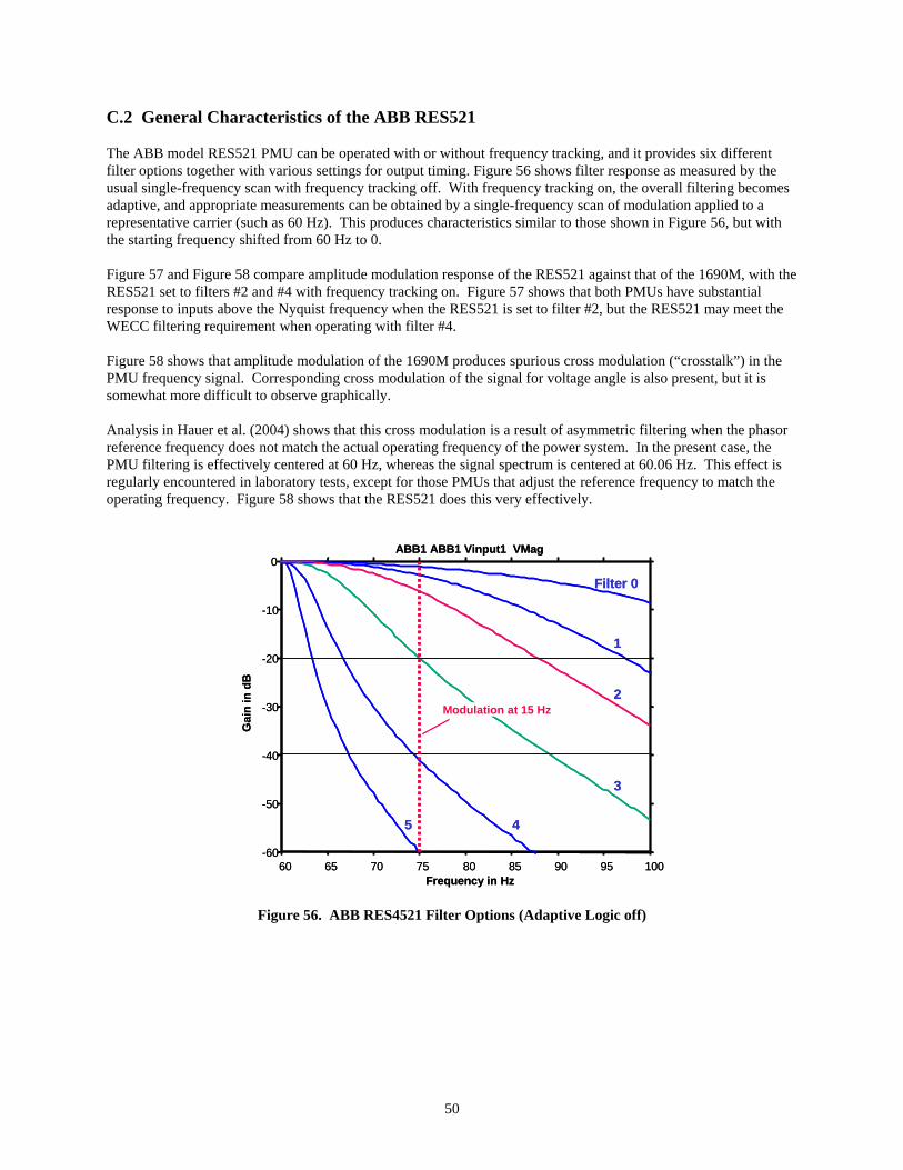
50
C.2 General Characteristics of the ABB RES521 The ABB model RES521 PMU can be operated with or without frequency tracking, and it provides six different filter options together with various settings for output timing. Figure 56 shows filter response as measured by the usual single-frequency scan with frequency tracking off. With frequency tracking on, the overall filtering becomes adaptive, and appropriate measurements can be obtained by a single-frequency scan of modulation applied to a representative carrier (such as 60 Hz). This produces characteristics similar to those shown in Figure 56, but with the starting frequency shifted from 60 Hz to 0. Figure 57 and Figure 58 compare amplitude modulation response of the RES521 against that of the 1690M, with the RES521 set to filters #2 and #4 with frequency tracking on. Figure 57 shows that both PMUs have substantial response to inputs above the Nyquist frequency when the RES521 is set to filter #2, but the RES521 may meet the WECC filtering requirement when operating with filter #4. Figure 58 shows that amplitude modulation of the 1690M produces spurious cross modulation (“crosstalk”) in the PMU frequency signal. Corresponding cross modulation of the signal for voltage angle is also present, but it is somewhat more difficult to observe graphically. Analysis in Hauer et al. (2004) shows that this cross modulation is a result of asymmetric filtering when the phasor reference frequency does not match the actual operating frequency of the power system. In the present case, the PMU filtering is effectively centered at 60 Hz, whereas the signal spectrum is centered at 60.06 Hz. This effect is regularly encountered in laboratory tests, except for those PMUs that adjust the reference frequency to match the operating frequency. Figure 58 shows that the RES521 does this very effectively.
60 65 70 75 80 85 90 95 100-60
-50
-40
-30
-20
-10
0ABB1 ABB1 Vinput1 VMag
Frequency in Hz
Gai
n in
dB
Filter 0
5 4
3
2
1
Modulation at 15 Hz
60 65 70 75 80 85 90 95 100-60
-50
-40
-30
-20
-10
0ABB1 ABB1 Vinput1 VMag
Frequency in Hz
Gai
n in
dB
Filter 0
5 4
3
2
1
Modulation at 15 Hz
Figure 56. ABB RES4521 Filter Options (Adaptive Logic off)
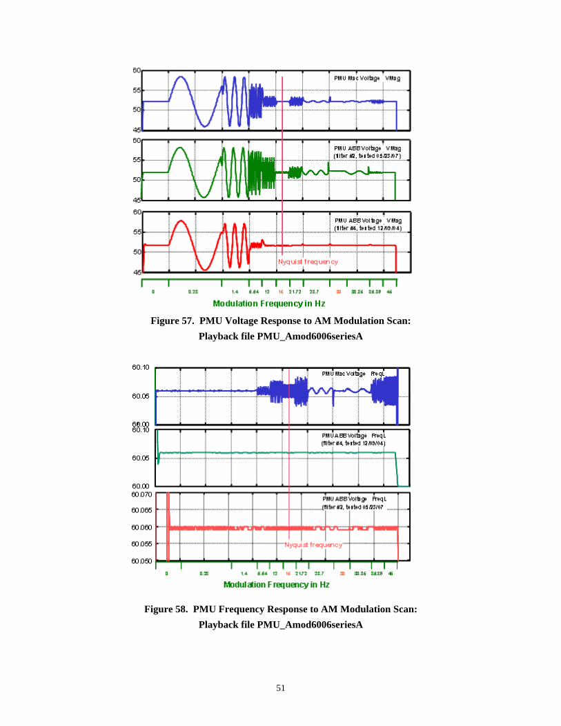
51
Figure 57. PMU Voltage Response to AM Modulation Scan:
Playback file PMU_Amod6006seriesA
Figure 58. PMU Frequency Response to AM Modulation Scan: Playback file PMU_Amod6006seriesA