Laboratory Multiparameter Meter Manual · Laboratory Multiparameter Meter Manual ... 5-pin Hach...
88
Cat. No. 54750-18 Laboratory Multiparameter Meter Manual © Hach Company, 2000. All rights reserved. Printed in the U.S.A. ap/dk 1/00 1ed
-
Upload
nguyenduong -
Category
Documents
-
view
233 -
download
0
Transcript of Laboratory Multiparameter Meter Manual · Laboratory Multiparameter Meter Manual ... 5-pin Hach...

Cat. No. 54750-18
Laboratory MultiparameterMeter Manual
© Hach Company, 2000. All rights reserved. Printed in the U.S.A. ap/dk 1/00 1ed

TRADEMARKS OF HACH COMPANY
AccuGrow®AccuVac®
AccuVer™
AccuVial™
Add-A-Test™
AgriTrak™
AluVer®
AmVer™
APA 6000™
AquaChek™
AquaTrend®
BariVer®
BODTrak™
BoroTrace™
BoroVer®
C. Moore Green™
CA 610™
CalVer®
ChromaVer®
ColorQuik®
CoolTrak®
CuVer®
CyaniVer®
Digesdahl®
DithiVer®
Dr. F. Fluent™
Dr. H. Tueau™
DR/Check™
EC 310™
FerroMo®
FerroVer®
FerroZine®
FilterTrak™ 660
Formula 2533™
Formula 2589™
Gelex®
H2O University™
H2OU™
Hach Logo®
Hach One®
Hach Oval®
Hach.com™
HachLink™
Hawkeye The Hach Guy™
HexaVer®
HgEx™
HydraVer®
ICE-PIC™
IncuTrol®
Just Add Water™
LeadTrak®
m-ColiBlue24®
ManVer®
MolyVer®
Mug-O-Meter®
NetSketcher™
NitraVer®
NitriVer®
NTrak®
OASIS™
On Site Analysis.Results You Can TrustSM
OptiQuant™
OriFlow™
OxyVer™
PathoScreen™
PbEx®
PermaChem®
PhosVer®
Pocket Colorimeter™
Pocket Pal™
Pocket Turbidimeter™
Pond In Pillow™
PourRite™
PrepTab™
ProNetic™
Pump Colorimeter™
QuanTab®
Rapid Liquid™
RapidSilver™
Ratio™
RoVer®
™
Simply AccurateSM
SINGLET™
SofChek™
SoilSYS™
SP 510™
Spec ™
StablCal®
StannaVer®
SteriChek™
StillVer®
SulfaVer®
Surface Scatter®
TanniVer®
TenSette®
Test ‘N Tube™
TestYES!SM
TitraStir®
TitraVer®
ToxTrak™
UniVer®
VIScreen™
Voluette®
WasteAway™
ZincoVer®
sension
√
2

TABLE OF CONTENTS
SAFETY PRECAUTIONS ....................................................................................................... 7SPECIFICATIONS.................................................................................................................... 9
OPERATION ........................................................................................................................ 13
SECTION 1 INTRODUCTION ...................................................................................... 151.1 Unpacking the Instrument ................................................................................................. 15
1.1.1 Standard Accessories ............................................................................................... 151.1.2 Optional Accessories ............................................................................................... 15
1.2 Keypad Description........................................................................................................... 161.3 Screen Description and Layout ......................................................................................... 181.4 Maintenance ...................................................................................................................... 201.5 Audible Signals ................................................................................................................. 20
SECTION 2 INSTRUMENT SETUP ............................................................................ 212.1 Instrument Description...................................................................................................... 212.2 Power Connection ............................................................................................................. 212.3 Probe Connections............................................................................................................. 21
2.3.1 Switching Between Conductivity and Dissolved Oxygen Modes ........................... 222.4 Turning the Meter On........................................................................................................ 222.5 Setup Menu Features Common to All Parameters ............................................................ 222.6 Printer and Computer Connections ................................................................................... 22
SECTION 3 pH OPERATION ........................................................................................ 253.1 pH Setup Menu Options.................................................................................................... 253.2 How to Change the pH Menu Options .............................................................................. 263.3 pH Calibration ................................................................................................................... 28
3.3.1 Performing a Calibration Using Automatically Recognized Buffers ...................... 283.3.2 Performing a Manual Calibration ............................................................................ 293.3.3 Reviewing the Calibration ....................................................................................... 30
3.4 Measuring Samples ........................................................................................................... 313.5 Millivolt Measurement ...................................................................................................... 31
SECTION 4 CONDUCTIVITY OPERATION ........................................................... 334.1 Conductivity Setup Menu Options .................................................................................... 334.2 How to Change the Conductivity Menu Options .............................................................. 354.3 Conductivity Calibration ................................................................................................... 37
4.3.1 Calibrating with a Known Standard......................................................................... 37
3

TABLE OF CONTENTS, continued
4.3.2 Calibrating by Adjusting the Cell Constant ............................................................ 384.3.3 Reviewing Calibrations ........................................................................................... 39
4.4 Measuring Conductivity ................................................................................................... 394.4.1 Measuring Low Levels of Conductivity .................................................................. 40
4.5 Measuring Total Dissolved Solids .................................................................................... 414.6 Measuring Salinity............................................................................................................ 414.7 Substances that May Affect Measurement ....................................................................... 424.8 Common Conversion Factors............................................................................................ 424.9 Theory of Conductivity Measurement .............................................................................. 43
SECTION 5 DISSOLVED OXYGEN OPERATION ................................................ 455.1 Dissolved Oxygen Setup Menu Options........................................................................... 455.2 How to Change the Dissolved Oxygen Menu Options..................................................... 455.3 DO Probe .......................................................................................................................... 46
5.3.1 Probe Assembly....................................................................................................... 465.4 Dissolved Oxygen Calibration.......................................................................................... 47
5.4.1 Probe Polarization ................................................................................................... 485.4.2 Zeroing the Probe .................................................................................................... 485.4.3 Calibration in Water Saturated Air .......................................................................... 495.4.4 Calibration to a Known Dissolved Oxygen Concentration ..................................... 515.4.5 Calibrating a Sample to Read 100% Saturation ...................................................... 525.4.6 Calibration Review.................................................................................................. 53
5.5 Measuring Dissolved Oxygen........................................................................................... 535.5.1 General Probe Operation......................................................................................... 535.5.2 Dissolved Oxygen Measurement ............................................................................ 545.5.3 Probe Storage .......................................................................................................... 555.5.4 Maintenance ............................................................................................................ 55
5.6 Using the BOD Accessory Kit.......................................................................................... 565.7 Making BOD Determinations........................................................................................... 565.8 Measuring Dissolved Oxygen in Water (0 to 20 mg/L).................................................... 575.9 Salinity Correction Factors ............................................................................................... 615.10 Pressure Conversions ...................................................................................................... 62
SECTION 6 STORING AND RECALLING DATA.................................................. 636.1 Storing Measurements ...................................................................................................... 636.2 Recalling Stored Data ....................................................................................................... 64
6.2.1 pH Data ................................................................................................................... 646.2.2 Conductivity Data ................................................................................................... 65
4

TABLE OF CONTENTS, continued
6.2.3 Dissolved Oxygen Data ........................................................................................... 656.3 Erasing Data ...................................................................................................................... 65
6.3.1 Erasing Single Data Points ...................................................................................... 656.3.2 Erasing Multiple Data Points................................................................................... 66
SECTION 7 PRINTING AND DATA TRANSFER ................................................... 677.1 Connecting to Printers/Computers .................................................................................... 67
7.1.1 Connection with the RS232 Cable........................................................................... 677.1.2 Connecting to a Printer ............................................................................................ 677.1.3 Connecting to a Personal Computer ........................................................................ 687.1.4 Using HachLink™ Communications Software with a PC ...................................... 70
7.2 Sending Data to Printers/Computers ................................................................................. 717.2.1 Sending Currently Displayed Data .......................................................................... 717.2.2 Sending Recalled Data Points.................................................................................. 717.2.3 Sending Multiple Data Points .................................................................................. 71
7.3 Printed Data Format .......................................................................................................... 737.4 PC Communication Codes ................................................................................................ 73
SECTION 8 TROUBLESHOOTING ............................................................................ 758.1 Error Codes ....................................................................................................................... 758.2 Meter Service Request Questionnaire ............................................................................... 76
GENERAL INFORMATION ...........................................................................................77REPLACEMENT PARTS AND ACCESSORIES.................................................................. 79HOW TO ORDER................................................................................................................... 82REPAIR SERVICE.................................................................................................................. 83WARRANTY .......................................................................................................................... 84CERTIFICATION ................................................................................................................... 85
5

6

SAFETY PRECAUTIONS
2.2 Power Connection on page 21
2.3 Probe Connections on page 21
2.6 Printer and Computer Connections on page 22
7.1 Connecting to Printers/Computers on page 67
7

8

SPECIFICATIONS
Specifications subject to change without notice.
General Specifications
Display: Custom LCD
Inputs:(1) 5-pin Hach pH/mV/temperature connector(1) 5-pin Hach conductivity or dissolved oxygen connector
Outputs: RS232
Power requirements:6–12 V dc; use either Hach supplied 115 or 230 V, 50/60 Hzexternal power supply or a customer provided supply with 50 mAoutput, 5.5-mm power plug with a 2.5 mm center post opening
Input impedance: >10l2 ohms
Installation Category: II
Environmental Requirements: 5–50 °C at 85% non-condensingrelative humidity
Meter dimensions: 215 x 25.4 x 8.37 cm (6 x 10.2 x 3.5 inches)
Enclosure: Water resistant (meets IP32), chemical-resistant.
pH Mode
Range:-2.00–19.99Resolution (selectable): 0.001/0.01/0.1Slope (meter allowable): 48–65 mV/decadeInstrument Drift: <40 µV/°CInput Bias Current: <±1 picoamp at 25 °C; ±4 picoamp overfull range
Millivolt ModeRange: -2000–2000 mVResolution: 0.1 mVAccuracy (meter only): ±0.2 mV or ±0.15% of the reading,whichever is greater
9

SPECIFICATIONS, continued
TemperatureRange: -10.0–110 °CResolution: 0.1 °CAccuracy: ±0.3 °C from 0–70 °C; ±1.0 °C from 70–110 °C
Conductivity ModeRange: 0–19.99 µS; 20–199.9 µS/cm; 200–1999 µS/cm;2–19.99 mS/cm; 20–199.9 mS/cmTDS: 0–50,000 mg/L as NaClSalinity: 0–42 ppt (‰)Temperature: -10–105 °C
Resolution:
Resolution:
Conductivity:
0.00–19.99 µS/cm 0.01 µS/cm
20.0–199.9 µS/cm 0.1 µS/cm
200–1999 µS/cm 1 µS/cm
2.00–19.99 mS/cm 0.01 mS/cm
20.0–199.9 mS/cm 0.1 mS/cm
TDS:
0.00–199.9 mg/L 0.1 mg/L
200–1999 mg/L 1 mg/L
2.00–19.99 g/L 0.01 g/L
20.0–50 g/L 0.1 g/L
Salinity:
0.1 ppt (‰)
Temperature
±0.1 °C
10

SPECIFICATIONS, continued
Accuracy:Conductivity: ±0.5% of rangeTDS: ±0.5% of full scaleSalinity: ±0.1 ppt (‰) (-2 to 35°C)Temperature: ±0.3 °C from 0–70 °C;
±1.0 °C from 70–110 °C
Conversion Factor for TDS: automatic or user adjustable
Temperature Compensation:Manual (user selected coefficient, % per °C) orAutomatic (non-linear based on NaCl solutions)
Dissolved Oxygen ModeRange: 0–20 mg/L (ppm), 0–200% sat.Accuracy: ±1% full scaleTemperature: 0–50 °C
Resolution:
Instrument drift: < 1%/day
Oxygen Concentration: 0.01 or 0.1 ppm (mg/L)
% Saturation: 0.1%
Temperature: 0.1 °C
11

12

OPERATION
13
DANGERHandling chemical samples, standards, and reagents can be dangerous. Review the necessaryMaterial Safety Data Sheets and become familiar with all safety procedures before handlingany chemicals.
DANGERLa manipulation des échantillons chimiques, étalons et réactifs peut être dangereuse. Lire les Fichesde Données de Sécurité des Produits (FDSP) et se familiariser avec toutes les procédures de sécuritéavant de manipuler tous les produits chimiques.
PELIGROLa manipulación de muestras químicas, estándares y reactivos puede ser peligrosa. Revise las fichasde seguridad de materiales y familiarícese con los procedimientos de seguridad antes de manipularproductos químicos.
GEFAHRDas Arbeiten mit chemischen Proben, Standards und Reagenzien ist mit Gefahren verbunden.Es wird dem Benutzer dieser Produkte empfohlen, sich vor der Arbeit mit sicheren Verfahrensweisenund dem richtigen Gebrauch der Chemikalien vertraut zu machen und alle entsprechendenMaterialsicherheitsdatenblätter aufmerksam zu lesen.
PERIGOA manipulação de amostras, padrões e reagentes químicos pode ser perigosa. Reveja a folha dosdados de segurança do material e familiarize-se com todos os procedimentos de segurança antesde manipular quaisquer produtos químicos.

14

SECTION 1 INTRODUCTION
The laboratory sension™378 Multiparameter Meter measurespH, conductivity, and dissolved oxygen. Other features include:
• User-friendly calibration
• 199-point internal datalogging for each of the threeparameters
• Bi-directional RS232 interface
• Adjustable corrections for temperature, salinity, and TDS
• Automatic correction for barometric pressure, and salinity
1.1 Unpacking the InstrumentRemove the instrument and accessories from the shippingcontainer and inspect each item for damage. Verify that all itemslisted on the packing slip are included. If any items are missing ordamaged, contact Hach Customer Service, Loveland, Colorado at1-800-227-4224. Customers outside the United States shouldcontact their regional Hach office or distributor.
1.1.1 Standard Accessories
• sension378 Multiparameter Meter Instrument Manual
Depending on which configuration you ordered, you will receivetwo or more of the following:
• pH electrode
• Conductivity electrode
• Dissolved oxygen electrode
• Calibration standards
1.1.2 Optional Accessories
• Probe Holder and Stirring Stand
• BOD Accessory Kit (See Section 5.6 on page 56.)
• Low Ionic Strength Sample Chamber
• Probe-related accessories (covered in the electrode manual)
15

SECTION 1, continued
1.2 Keypad DescriptionFigure 1 shows the keypad. Table 1 explains key functions.
Figure 1 sension378 Keypad
16

SECTION 1, continued
Table 1 Keys and Description
Key Description
Exit/Power On-Off When power is off:
• Turns the instrument on and opens the most recently used reading mode.
In the reading mode:
• Turns the instrument off.
From other power modes:
• Exits the current mode and moves toward power off.
• Acts as a “no” answer when the question mark is flashing.
• Cancels the current operation without saving changes.
Arrow Keys Scroll between options in Setup mode.Scroll through data points in Store and Recall modes.Scroll between the option to print or erase one data point and the option to print orerase multiple data points.
READ/ENTERKey
Accepts numerical input.Acts as a “yes” answer when the question mark is flashing.Allows user to edit a setup when the setup number is flashing.Accepts the current setup option when that option is flashing.Initiates a measurement when the meter has stabilized in the Display LockEnabled mode and during calibration.
RECALL Key Recalls stored sample data of the current reading parameter type (from thereading mode only).
STORE Key Initiates storage of the current (displayed) measurement (from the readingmode only).
ERASE Key Erases recalled data points.
CON/TDS/SAL Initiates conductivity reading. Toggles between conductivity, total dissolved solids,and salinity.
pH/mV Initiates pH reading. Toggles between pH and mV.
DO % Key Toggles between dissolved oxygen concentrations displayed as % saturation andmg/L in Reading, Data Recall, and Calibration Review modes.
PRINT Key Sends current or recalled data to a printer or a computer via the RS232 port.From Cal Review, prints current calibration data.
TIME Key From the reading mode, shows current time (one press) and date (two presses). InRecall Data and Calibration Review modes, the key toggles between the time anddate of the stored measurement.
CAL Key Enters Calibration mode (from the reading mode only).
REVIEW Key Enters Calibration Review mode (from the reading mode only).
SETUP/CE Key Enters Setup mode (from the reading mode only).Clears a numeric entry when the keypad icon is displayed.
17

SECTION 1, continued
1.3 Screen Description and LayoutThe screen, or the display, is divided into two areas by ahorizontal line. The upper area shows measurements or standardvalues, the current operation mode, sample temperature, units,error codes, and a stable reading indicator. The lower area showsthe active navigation keys (ENTER, EXIT, and UP ARROW andDOWN ARROW keys). It also shows when the numeric keypad isactive.
Figure 2 shows the icons and fields that appear on the display.Table 2 describes each icon and field. To see all iconssimultaneously, hold down the POWER key for several seconds.
Figure 2 sension378 Display Layout
18

SECTION 1, continued
Table 2 Display Descriptions
Item No. Description
1 Indicates meter is in Calibration mode. When this icon and the ? are flashing, a calibrationis necessary.
2 Indicates meter is in Calibration Review mode.
3 Indicates the battery is low.
4 Indicates data is being or will be sent to a printer/computer, or that a printing setup hasbeen accessed.
5 Indicates currently displayed recalled data is being or will be erased.
6 Indicates meter is in Setup mode.
7 Indicates all data points are being printed or erased.
8 Refers to Setup, Sample, or Standard when any of those words are displayed next to thenumber. For example, if Standard and 1 are displayed, the meter is measuring Standard 1.
9 When flashing along with the CAL icon, indicates that calibration is needed for the currentreading parameter. Otherwise, it indicates that user input is required.(In this case, press ENTER for “yes” and EXIT for “no”.)
10 Label for sample number in Data Store, Recall, or Erase modes.
11 Indicates the meter is measuring a standard (standard number is displayed above).
12 Indicates the displayed number is the electrode slope.
13 Main numeric display field. Displays values for readings, slope, and setups.
14 Indicates measurement units.
15 Indicates the meter is using the default temperature value to calculate temperaturecorrection.
16 Indicates the temperature units in use (choice of °C or °F).
17 Indicates value displayed in small numerical field (item 18) is in millivolts.
18 Displays temperature value, date, or pH calibration offset.
19 Indicates an inactive key has been pressed and that function is not allowed.
20 Indicates the ENTER key is active.
21 Indicates the date is being set (in Setup mode) or displayed (in Reading, Cal Review, orData Recall mode).
22 Indicates arrow keys are active.
23 Indicates that the instrument is reading or recalling conductivity in terms of TDS. Ifcorrection icon is also on, it indicates that the TDS correction factor has been changed fromthe factory default.
24 Indicates that the meter is in Correction mode. Indicates that one or more correction factorsetups have been changed from their default settings. These include salinity correction forDO, and temperature and/or TDS correction factors for conductivity.
25 Indicates EXIT key is active.
19

SECTION 1, continued
1.4 MaintenanceThe meter is designed to be maintenance-free. If the meter getsdirty, wipe the surface with a damp cloth. Use a cotton-tippedapplicator to clean or dry the connectors if they get wet.
1.5 Audible SignalsThe meter will beep under certain conditions:
• when a non-functional key press is made (one beep)
• when measurement stability is reached during calibration(three beeps)
• in the reading mode, when the display lock is turned on andstability is reached (three beeps)
• in case of an error or malfunction (one beep).
26 If the thermometer icon and the correction icon are on, a temperature correction other thanthe factory default is in use. If the thermometer and the (Off) icon display, temperaturecompensation is off.
27 Indicates numeric key functions are active.
28 In Conductivity mode, it indicates the meter is displaying sample salinity. In DO mode,indicates that a linear salinity correction is being applied to the dissolved oxygenmeasurement and that the salinity corrected value is displayed.
29 Indicates the display is locked. Pressing read initiates another measurement.
30 Indicates a meter function problem.
31 Indicates whether an associated setup setting is On or Off.
32 Indicates faulty probe connection or incorrect probe attached.
33 Indicates that the meter is reading or recalling a dissolved oxygen measurement. Alsoshown for setups that apply only to DO.
34 Indicates that the instrument is reading or recalling a conductivity measurement. Alsoshown for setups that apply only to conductivity.
35 Indicates the signal from the sample is not yet stable. When the icon disappears, thereading is stable and may be recorded.
36 Asks if the calibration or the displayed sample data should be stored. Used with ? icon.
37 Indicates the time is being displayed or set. Used with large display (item 13).
38 Indicates the meter is in Recall mode and the displayed data is stored data.
Table 2 Display Descriptions (Continued)
Item No. Description
20

SECTION 2 INSTRUMENT SETUP
2.1 Instrument DescriptionThe sension™378 Multiparameter Meter is designed forlaboratory use and operates on 115/230 V ac power.
2.2 Power ConnectionA 115 or 230 V ac pin adapter connects the meter to line power.Plug the pin end of the adapter into the pin connector in the meter(see Figure 3). Then plug the adapter into the outlet.
Figure 3 sension378 Power and Probe Connections
2.3 Probe ConnectionsAttach electrodes with 5-pin connectors to the sensor inputs withthe arrow on the probe connector pointed toward 12 o’clock. Pushthe electrode connector toward the instrument.
21

SECTION 2, continued
2.3.1 Switching Between Conductivity and Dissolved Oxygen ModesThe blue connector is for either the DO or conductivity probe.The meter remembers which of these probes was used last. If youselect the parameter that was not used last, the meter will promptfor an electrode change and ask you to confirm. Press ENTER toconfirm the new probe and initiate the reading. Press EXIT toreturn the meter to the previous mode.
2.4 Turning the Meter OnAfter plugging the meter into the wall, turn the instrument onusing the I/O key (located on the upper left side of the keypad).Press the key once to supply power to the instrument. The displaywill show the software version number, perform internal tests,then default to the reading mode.
2.5 Setup Menu Features Common to All ParametersThe setup menu structure on the sension378 MultiparameterMeter varies depending on the reading mode (pH, conductivity, ordissolved oxygen). The setups for Time, Date, Year, andTemperature Units apply to all parameters. Other menusetups, including Display Lock, Auto Print Interval, andResolution, allow users to select different settings fordifferent parameters.
2.6 Printer and Computer ConnectionsThe meter can send data to a computer or printer via the 9-pinserial port (see Figure 4). The printer cable and computercable are different. The printer cable is a 9-pin to 25-pin cableand the computer cable is a 9-pin to 9-pin cable. Be sure to usethe correct cable.
The meter can print to serial printers without an adapter. Forparallel printers, a converter and cable adapter are required. TheCitizen PN60 printer requires a special Citizen adapter. Pressingthe PRINT key will send the currently displayed data to the printer.The data may be either a current measurement or recalled data.
To send data to a computer, connect the 9-pin serial port on themeter to a 9-pin serial port of the computer. Press the PRINT keyto send the currently displayed data to the computer. The datamay be either a current measurement or recalled data.
22

SECTION 2, continued
To control the meter remotely from a PC, see Section 7.4 onpage 73.
Figure 4 Serial Port, 9-pin
23

24

SECTION 3 pH OPERATION
3.1 pH Setup Menu OptionsTable 3 describes the options available in the pH Setup Menu.
Display Lock— When Display Lock is on, the stable reading islocked on the display. A new reading is initiated by pressing theREAD key. When Display Lock is off, the meter will continuouslymonitor pH. Stabilizing . . . may appear again if the sample pH ischanging or the probe drifts. The default setting is off.
pH, DO, and conductivity have separate Display Lock settings.
Auto Buffer Recognition— Allows users to select 7.00 pH or6.86 pH as the automatically recognized, mid-range buffer. Donot use 6.86 pH buffer if the setting is 7.00 pH. Do not use 7.00pH buffer if the setting is 6.86 pH.
Auto Print Interval— Activates the meter’s automatic datatransfer (Print) function.
Table 3 pH Setup Options
SetupNumber
Setup Description Option DescriptionDefaultSetting
1 Time 00:00 to 23:59 00:00
2 Date 01/01 to 12/31 01/01
3 Year 2000–2099 2000
4 Temperature units °C, °F °C
5 Display lock On: Lock iconOff: Lock icon and (Off) icon
Off
6 Resolution 0.0, 0.00, 0.000 0.00
7 Auto buffer recognition 6.86 pH, 7.00 pH 7.00 pH
8 Auto print interval Off, 10 sec., 30 sec., 1 min., 5 min., 20 min., 1 hr.,2 hrs., and 6 hrs.
Off
25

SECTION 3, continued
The automatic data transfer function automatically sends datadepending upon the time interval selected. Time intervals areselected from the following options: 10 seconds, 30 seconds,1 minute, 5 minutes, 20 minutes, 1 hour, 2 hours, or 6 hours. Thedefault setting is off.
Accessing Calibration mode or Setup mode halts automatic datatransfer. Also, if the meter has been set to the Lock mode usingSetup 1, the meter will not send data. When the meter is in Lockmode and the READ key is pressed, automatic data transfer willoccur at selected time intervals only until the meter stabilizes andthe value in the display is locked.
To keep transferring pH data, leave the meter in pH Readingmode connected to line power.
Each time data transfer occurs, the Print icon will momentarilyappear at the top of the display.
When auto print is on, the instrument will send data at thespecified interval, as long as the instrument is in the pH Readingmode.
3.2 How to Change the pH Menu OptionsTo access the pH Setup menu:
1. Turn on the meter and press the pH key.
2. Press the SETUP key.
3. Use the UP ARROW and DOWN ARROW keys to scrollbetween the desired options.
Table 4 shows how to change each specific setup option.
26

SECTION 3, continued
Table 4 How to Change pH Menu Options
Setup How to Get There
Setup 1Time
From any reading mode, press SETUP.Press ENTER.Use the number keys to change the time.Press ENTER to accept the time.
Setup 2Date
From any reading mode, press SETUP.Press the UP ARROW until the setup number is 2.Press ENTER.Press the UP or DOWN ARROW to toggle the date format between d/M(day/month) and m/d (month/day).Use the number keys to change the date.Press ENTER to accept the date.
Setup 3Year
From any reading mode, press SETUP.Press the UP ARROW until the setup number is 3.Press ENTER.Use the number keys to change the year.Press ENTER to accept the year.
Setup 4Temperature Units
From any reading mode, press SETUP.Press the UP ARROW until the setup number is 4.Press ENTER to toggle between °C and °F. The default is °C.When the desired option is selected, press EXIT to return to the reading mode.
Setup 5Display Lock
From pH Reading mode, press SETUP.Press the UP ARROW until the setup number is 5.Press ENTER to toggle display lock off and on.When the desired option is selected, press exit to return to the reading mode.
Note: When display lock is disabled, the Display Lock icon and (Off) are displayed.When this feature is enabled, only the Display Lock icon is displayed.
See Section 3.1 for more information about this setup.
Setup 6Measurement
Resolution
From pH Reading mode, press SETUP.Press the UP ARROW until the setup number is 6.Press ENTER to toggle between the three resolution options.When the desired option is selected, press EXIT to return to the reading mode.
Setup 7Auto BufferRecognition
From pH Reading mode, press SETUP.Press the UP ARROW until the setup number is 7.Press ENTER to toggle between the buffer value of 6.86 and 7.00.When the desired option is selected, press EXIT to return to the reading mode.See Section 3.1 for more information about this setup.
Setup 8Auto PrintIntervals
From pH Reading mode, press SETUP.Press the UP ARROW until the setup number is 8.Press ENTER.Change the print interval by pressing the UP ARROW and DOWN ARROW keys.Press ENTER to accept the print interval.
27

SECTION 3, continued
3.3 pH CalibrationHach recommends a daily two- or three-point calibration usingbuffers that bracket the sample pH. Store and compare the dailyslope values to verify that the electrode is working properly.
3.3.1 Performing a Calibration Using Automatically Recognized Buffers
1. Prepare two or three pH buffers according to the electrodeinstruction manual. Choose from 1.68, 4.01, 7.00 (or 6.86),10.01, and 12.45 pH buffers.
Note: Use a 6.86 or 7.0 pH buffer for the mid-range buffer. To view orchange the setting for the mid-range buffer see Section 3.2.
2. Turn the instrument on. From the pH Reading mode, pressCAL. CAL and flashing ? will appear in the upper displayarea, along with Standard and 1.
3. Place the pH electrode in one of the buffers.
4. Press READ. The instrument will automatically recognize thecalibration buffer value. The temperature and pH values willbe updated until a stable reading is reached.
Note: The pH values for the buffers are given for 25 °C. If the calibrationbuffer temperature is not 25 °C, the pH values displayed for thebuffers will reflect the correct pH value for the calibration buffertemperature.
Note: If the meter is measuring in pH Reading mode, it automaticallymoves to the next calibration step when the meter stabilizes(indicated by three beeps). If measuring in mV Reading mode, thethree beeps will still sound when the stabilization occurs. PressENTER to accept the reading.
5. When the reading has stabilized or been accepted, thestandard number will change to 2.
6. Remove the probe from the first buffer and rinse withdeionized water. Place the probe in the second buffer.
7. Press READ. The temperature and pH values will be updateduntil a stable reading is reached.
8. When the reading has stabilized or been accepted, thestandard number will change to 3. (To accept this calibration
28

SECTION 3, continued
after two points, press EXIT. Press ENTER to accept thecalibration or EXIT to cancel the calibration without saving it.)
9. Remove the probe from the second buffer and rinse withdeionized water. Place the probe in the third buffer.
10. Press READ. The temperature and pH values will be updateduntil a stable reading is reached.
11. When the reading has stabilized or been accepted, the slopevalue and the Store and ? icons will appear.
12. To save the calibration and return to the reading mode, pressENTER. To exit the calibration without saving it and return tothe reading mode, press EXIT.
3.3.2 Performing a Manual Calibration
1. Prepare two or three pH buffers according to the electrodeinstruction manual.
2. Turn the instrument on. From the pH Reading mode, pressCAL. Functional keys will appear in the lower left displayarea. CAL and ? will appear in the upper display area, alongwith Standard and 1. The numeric keypad will become active.
3. Place the pH electrode in a buffer. (Starting with the lowestpH makes it easy to keep track.)
4. Enter the pH value of the buffer using the number keys andpress ENTER. A flashing underscore (__) indicates where thenext number will be placed.
5. The pH value entered will appear and the temperature and pHvalues will be updated until a stable reading is reached.
6. When the reading has stabilized, the standard number willchange to 2. (If measuring in the mV Reading mode, pressENTER to accept the reading and continue.)
7. Rinse the electrode and place it in the next buffer.
8. Enter the pH value of the buffer using the number keys asdescribed above. Press ENTER.
29
SECTION 3, continued
9. When the reading has stabilized, the standard number willchange to 3. (If measuring in the mV Reading mode, pressENTER to accept the reading and continue.)
10. If desired, repeat steps 7–9 for a third buffer. If not, pressEXIT and go to the next step.
11. The slope value and the Store and ? icons will appear.
12. To save the calibration and return to the reading mode, pressENTER. To exit the calibration without saving it and return tothe reading mode, press EXIT. After the calibration is stored,the meter is immediately ready to begin measuring samples.See Section 3.4 on page 31 for pH sample measurements.
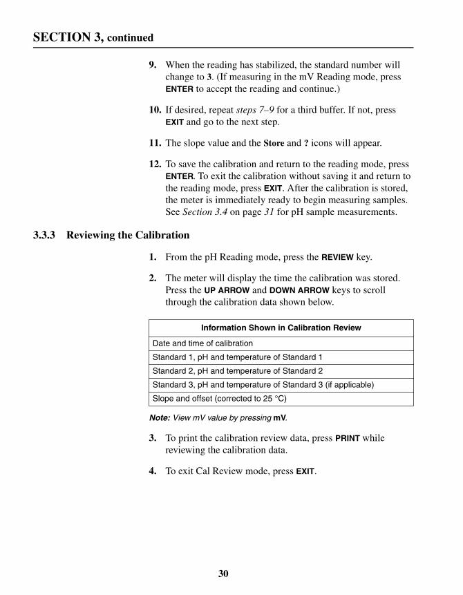
3.3.3 Reviewing the Calibration
1. From the pH Reading mode, press the REVIEW key.
2. The meter will display the time the calibration was stored.Press the UP ARROW and DOWN ARROW keys to scrollthrough the calibration data shown below.
Note: View mV value by pressing mV.
3. To print the calibration review data, press PRINT whilereviewing the calibration data.
4. To exit Cal Review mode, press EXIT.
Information Shown in Calibration Review
Date and time of calibration
Standard 1, pH and temperature of Standard 1
Standard 2, pH and temperature of Standard 2
Standard 3, pH and temperature of Standard 3 (if applicable)
Slope and offset (corrected to 25 °C)
30

SECTION 3, continued
3.4 Measuring SamplesAfter successful calibration, follow the steps below to measuresamples. See the electrode manual for more information andspecific procedures that use the electrode.
1. Rinse the electrode in deionized water.
2. Place the electrode in the sample. Press READ. Stabilizing...will appear, along with the sample temperature and the pH ormV reading. These values may fluctuate until the systemis stable.
3. When the reading is stable Stabilizing... will disappear. If theDisplay Lock is enabled, the display will “lock in” on the pHor mV and sample temperature. If the Display Lock is off, thedisplay will show the current reading and temperature, but thevalues may fluctuate.
4. Record or store the pH or mV value.
5. Remove the electrode from the sample, rinse with deionizedwater and place the electrode in the next sample. Repeatsteps 2–4 for each sample.
6. When finished, turn the meter off. Rinse the electrode withdeionized water and gently blot dry. Replace the protectivecap on the electrode and put the electrode in the electrodeholder. Consult the electrode manual for storage instructions.
3.5 Millivolt MeasurementThe meter can measure absolute millivolts (mV). To display thecurrent millivolt reading, press the mV key from the pH Readingmode. The mV value is displayed with mV in the units field.
Absolute millivolts are displayed with 0.1 mV resolution in therange of -2000 to 2000.
31

32

SECTION 4 CONDUCTIVITY OPERATION
4.1 Conductivity Setup Menu OptionsTable 5 describes the options available in the ConductivitySetup Menu.
Temperature Correction Value— Allows selection of a linearor non-linear temperature correction function. The non-linearcoefficient has been determined from measurements usingaqueous NaCl solutions; for most freshwater samples, this is thebest setting. If the linear function is chosen, the measuredconductivity values are automatically temperature-correctedbased on the specified temperature coefficient and the selectedreference temperature. The linear temperature correction valuefor the meter has a default value of 2% per 1 °C.
Table 5 Setup Options
SetupNumber
Setup Description Option Description Default Setting
1 Time 00:00 to 23:59 00:00
2 Date 01/01 to 12/31 01/01
3 Year 2000–2099 2000
4 Temperature units °C, °F °C
5 Display lock On: Lock iconOff: Lock icon and (Off) icon
Off
6 TemperatureCorrection Factor(Thermometer icon)
Non-linear NaCl orNon-linearNaCl
7 TDS Correction Factor Non-linear for NaCl or numeric value forconverting µS/cm to TDS
Non-linearNaCl
8 Auto-print interval Off, 10 sec., 30 sec., 1 min., 5 min., 20 min.,1 hr., 2 hrs., and 6 hrs.
Off
9 ReferenceTemperature Selection(Thermometer icon)
20° C or 25° C 25° C
10 TemperatureCorrection(Thermometer icon)
On, Off(Off) icon for off
On. If “raw”conductivity isdesired, suchas with a soilcup, turn offtemperaturecorrection.
Numeric value[ ]%°C
------------------------------------------------
33

SECTION 4, continued
Conductivity of samples that contain other salts or ions maychange at a different rate with temperature. This rate depends onthe solution temperature, the ion concentration, and the referencetemperature selected, and should be determined experimentally.Once determined, enter the temperature correction value usingthis setup option.
The Temperature Correction option must be on for the meter touse a temperature correction value (see Section 4.2).
Table 6 shows some typical temperature coefficients (percentchange of conductivity per °C).
TDS Correction Factor— This setup lets the user choose alinear or non-linear conversion from conductivity to TDS. TDSmeasurements use conductivity readings that are temperature-compensated. When the linear conversion is chosen, the meteruses the reference temperature and the temperature-correctionoption to determine temperature-corrected conductivity. Thenon-linear (NaCl) conversion uses the non-linear temperaturecorrection function and a reference temperature of 25 °C,regardless of the current temperature factor setting (Setup 6), toconvert temperature-compensated conductivity readings toTDS readings.
In TDS Reading mode, the TDS icon indicates the meter isreading TDS. If the correction icon is also shown, the meter isusing a linear conversion. If the correction icon does not appear,the meter is using the default non-linear NaCl conversion.
Table 6 Percentage Change of Conductivity per Degree C
Solution Percent/°C
Ultrapure Water 4.55
Salt (NaCl) 2.125
NaOH 1.72
Dilute Ammonia 1.8810
10% HCl 1.325
5% Sulfuric Acid 0.9698
Sugar Syrup 5.64
34

SECTION 4, continued
Reference Temperature— Conductivity standards typicallyhave a reference temperature noted on their container. Whenmeasuring solutions that are not at the reference temperature, themeter automatically adjusts the reading to the conductivity valuethat would have been measured if the sample had been at thereference temperature. The reference temperature choices in themeter are 20 or 25 °C. The reference temperature default settingis 25 °C.
Temperature Correction Off and On— Because the activity ofions in solutions varies with temperature, conductivitymeasurements are typically corrected for the sample temperature.To obtain conductivity measurements that are not temperaturecorrected (i.e., using the soil cup), turn this option off. For typicalmeasurements, ignoring the effects of temperature can result insignificant error. Salinity and TDS always require temperaturecompensation, so when those forms of conductivity are beingmeasured, this setup is ignored. The probe supplied with themeter measures temperature with a thermistor for automatictemperature compensation.
When the thermometer and Off icons appear in the reading mode,the instrument is not correcting the measured conductivityfor temperature.
In Setup mode, when the setting is disabled, the thermometer iconand (Off) are displayed. When this feature is enabled, thethermometer icon is displayed without the (Off) icon.
4.2 How to Change the Conductivity Menu OptionsTo access the Conductivity Setup menu:
1. Turn on the meter and press the CON key.
2. Press the SETUP key. The arrow icons that appear indicatethat additional options are available within the menu.
3. Use the UP ARROW and DOWN ARROW keys to scrollbetween the desired options.
To set the time, date, year, or temperature units, remain inConductivity mode, but follow the instructions in Table 4 onpage 27. Table 7 shows how to change the other setup options.
35

SECTION 4, continued
Table 7 How to Change Conductivity Menu Options
Setup How to Get There
Setup 5Display Lock
From Conductivity Reading mode, press SETUP.Press the UP ARROW until the setup number is 5.Press ENTER to toggle display lock off and on.When the desired option is selected, press EXIT to return to the reading mode.When display lock is disabled, the Display Lock icon and Off are displayed. When thisfeature is enabled, only the Display Lock icon is displayed.See Section 4.1 for more information about this setup.
Setup 6Temperature
Correction Value
From Conductivity Reading mode, press SETUP.Press the UP ARROW until the setup number is 6.Press ENTER.To select the non-linear function, press the UP or DOWN ARROW key until thedisplay shows NaCl. Press ENTER to accept the setting.
To select a linear conversion, scroll until the correction coefficient appears(e.g., 2.000%).Enter the desired value using the numeric keypad.Press ENTER to accept the value. If a number entry error occurs, start over bypressing CE.
Note: If the compensation factor is set to 0.00%, the conductivity readings will not becorrected for temperature.
When the desired option is selected, press EXIT to return to the reading mode.See Section 4.1 for more information about this setup.
Setup 7TDS Correction
Factor
From Conductivity Reading mode, press SETUP.Press the UP ARROW until the setup number is 7.Press ENTER.Press the UP or DOWN ARROW keys to switch between linear and non-linearcorrection functions.To choose a non-linear conversion, scroll until a flashing NaCl appears, thenpress ENTER.To select a linear conversion, scroll until the conversion coefficient appears. Usethe numeric keypad to set the value of the coefficient, then press ENTER. If annumber entry error occurs, start over by pressing CE.
When the desired option is selected, press EXIT to return to the reading mode.See Section 4.1 for more information about this setup.
Setup 8Auto PrintIntervals
From Conductivity Reading mode, press SETUP.Press the UP ARROW until the setup number is 8.Press ENTER.Change the print interval by pressing the UP ARROW and DOWN ARROW keys.Press ENTER to accept the print interval.
36

SECTION 4, continued
4.3 Conductivity CalibrationCalibrate the meter before use. There are two ways to calibratethe meter:
1. Use NaCl standards of known electrolytic conductivity. SeeSection 4.3.1 for instructions on this calibration method.
2. Enter/adjust the cell constant of the conductivity probe. SeeSection 4.3.2 for instructions on this calibration method.
4.3.1 Calibrating with a Known StandardHach's Conductivity probe is shipped with a 1000 µS/cm standardsolution. For typical applications with conductivity of0–10,000 µS (10 mS/cm), calibrate with this standard to achievethe accuracy specified for the meter. Outside this range, calibrateusing a standard that lies closer to the measurement range. Ingeneral, using a calibration standard that is closer to yourmeasurement range results in greater accuracy. Hach offersseveral conductivity standards.
1. Make sure the meter is in Conductivity Reading mode.
2. Make sure that the reference temperature in conductivitySetup 9 matches the reference temperature of the standard.
3. Place the probe in a conductivity standard that is in theexpected range of the samples. Agitate the probe to dislodgebubbles in the cell. Avoid resting the probe on the bottom orside of the container.
Setup 9Reference
Temperature
From Conductivity Reading mode, press SETUP.Press the UP ARROW until the setup number is 9.Press ENTER to toggle between 20° C and 25° C. The default is 25° C.Press EXIT to return to the reading mode.See Section 4.1 for more information about this setup.
Setup 10TemperatureCorrectionOff and On
From Conductivity Reading mode, press SETUP.Press the UP ARROW until the setup number is 10.Press ENTER to toggle between (off) and on.Press EXIT to return to the reading mode.See Section 4.1 for more information about this setup.
Table 7 How to Change Conductivity Menu Options (Continued)
Setup How to Get There
37

SECTION 4, continued
4. Press CAL. Icons that represent the active navigation key willappear in the lower part of the display.
The meter will recall the most recent type of calibration. Look atthe units field to see what kind of calibration is active. The unitswill be one of the following forms:
5. Scroll to the preferred units using the UP or DOWN ARROWS.
6. Use the number keys to change the numeric value, if desired.It is not necessary to fill up the numeric entry screen beforemoving on. To clear the numeric display, press CE.
7. When the value and units are correct, press ENTER tocalibrate on the standard. The meter automatically correctsthe calibration measurement to the selected referencetemperature using the NaCl-based, non-linear temperaturecoefficient.
8. The meter will return to Conductivity Reading mode whenthe calibration is finished.
4.3.2 Calibrating by Adjusting the Cell ConstantThe cell constant should be consistent over most of themeasurement range. However, samples having a conductivityhigher than 50 mS/cm may have a slightly different cell constantthan samples with a conductivity less than 50 mS/cm. Follow thesteps below to measure samples with conductivity above andbelow 50 mS/cm without recalibrating.
1. Follow Section 4.3.1 to calibrate the meter on a knownstandard in the range of interest. Be sure the meter is in theConductivity Reading mode before calibrating it.
2. After the calibration is complete, press REVIEW. The cellconstant for the probe will be displayed. Record this value.
Units Calibration Method
µS/cm Known standard expressed in µS/cm
mS/cm Known standard expressed in mS/cm
1/cm Enter/adjust cell constant (see Section 4.3.2)
38

SECTION 4, continued
3. Press the UP ARROW to display the standard concentrationvalue. Record this value. Press EXIT.
4. As the conductivity of the sample measurements change, thecell constant can be updated without calibrating with astandard. First, press CAL.
5. Functional keys will appear in the lower part of the display.CAL and ? will appear in the upper display. The main displaywill show the last value used for calibration.
6. Press the DOWN ARROW until the current cell constant isdisplayed (in cm–1).
7. Use the numeric keypad to enter the cell constant from aprevious calibration that applies to the current sample. If anumber entry error occurs, start over by pressing CE.
8. Press ENTER. When the calibration is complete, the meterwill return to the reading mode.
4.3.3 Reviewing Calibrations
1. From the reading mode, press the REVIEW key.
2. To print a calibration report, press the PRINT key.
3. The display will show the date of the most recent calibration.Press the TIME key to see the calibration time. Press the UPARROW to continue.
4. The display will show the value of the standard used forcalibration. Go to step 5 if the calibration was performed bysetting the cell constant. Otherwise, press the UP ARROWonce.
5. The meter will display the current cell constant in cm–1. Toexit Cal Review mode, press EXIT.
4.4 Measuring ConductivityTo measure conductivity with the sension378 meter, press theCON/TDS/SAL key. The conductivity icon will appear in the lowerleft corner of the screen and the TDS and Sal icons do not appear.The instrument will automatically select the appropriate range
39

SECTION 4, continued
and units and will display the conductivity value for the samplebeing measured.
For conductivity, place the probe into the sample and make surethe slot on the end of the probe is totally immersed. Agitate thesample with the probe for 5–10 seconds to remove bubbles thatmay be trapped in the slot.
Table 8 shows the conductivity ranges of common solutions.
4.4.1 Measuring Low Levels of ConductivityWhen the non-temperature corrected conductivity is less than1 µS/cm, the meter automatically uses the temperature correctioncoefficients for pure water for the reference temperature selected(derived from ASTM method D 1125-91, page 253, 1993).
For best accuracy when reading low conductivity levels, Hachrecommends using the Low Ionic Strength Chamber to preventgases in the atmosphere from changing the conductivity level.
1. Make sure the meter is using the non-linear NaCl temperaturecorrection (see Section 4.2 on page 35).
2. Zero the dry probe by pressing READ and CAL at the sametime. The probe must be dry to obtain a correct value.
3. Calibrate using the 180 µS/cm standard (see Section 4.3.1 onpage 37).
4. Thoroughly rinse the electrode with the sample.
Table 8 Conductivity Range of Common Aqueous Solutions
Sample Type Conductivity Range
High pressure boiler water <0.1 µS/cm to 0.2 µS/cm
Demineralized water 1 µS/cm to 80 µS/cm
Drinking water 100 µS/cm to 1 mS/cm
Wastewater 85 µS/cm to 9 mS/cm
Surface water 100 µS/cm to 10 mS/cm
Industrial process water 8 mS/cm to 130 mS/cm
Concentrated acids and dyes 85 mS/cm to >1000 mS/cm
40

SECTION 4, continued
5. Insert the conductivity probe into the LIS chamber. Start thesample flow into the LIS chamber.
6. When the conductivity value stabilizes, store or record it.
Note: If the non temperature-corrected conductivity of the sampleincreases above 1 µS/cm, the meter will use the temperaturecorrection coefficients for NaCl. This may cause a noticeable jump inthe displayed conductivity reading.
4.5 Measuring Total Dissolved SolidsTo measure TDS with the sension378 meter, press theCON/TDS/SAL key until the TDS icon appears in the lower leftcorner of the screen. The instrument will display the TDS valuefor the currently displayed conductivity measurement.
The standard method of determining TDS is to evaporate thesample to dryness at 180 °C, then weigh the residue.Alternatively, calculate the concentration of sodium chloride thatwould have the same conductivity as the sample at the sametemperature. The sension378 meter reports a sample’s TDSvalue in mg/L of sodium chloride by comparing the sampleconductivity and temperature to data stored in the meter’smemory. Data were obtained from empirical procedures usingsodium chloride solutions.
4.6 Measuring SalinityIf you have a DO probe and plan to use salinity measurements toadjust DO measurements, follow the steps below:
1. From Salinity Reading mode, press the UP ARROW. Theinstrument will ask whether you would like to use the currentmeasurement as the salinity correction factor for DOmeasurements.
2. Press ENTER to accept or EXIT to cancel. If you select ENTER,Setup 7 in DO mode changes accordingly.
To measure salinity with the sension378 meter, press theCON/TDS/SAL key until the SAL icon appears in the lower leftcorner of the screen. The instrument will display the salinityvalue for the sample being measured.
41

SECTION 4, continued
Salinity, a measure of the mass of dissolved salts in a given massof solution, is used to describe seawater, natural, and industrialwaters. Salinity is a relative scale based on a potassium chloride(KCl) solution. A salinity value of 35 is equivalent to a KClsolution containing 32.4356 g KCl in 1 kg of solution at 15 °C.Salinity is measured in ‰ (ppt—parts per thousand). The metercalculates the salinity based on the Extended Practical SalinityScale of 1978, as referenced in 17th edition of Standard Methods,25200 B. The applicable range is 0 to 42‰ and –2 to 35 °C.
4.7 Substances that May Affect MeasurementWhen measuring very low conductivity levels (< 2 µS), protectthe sample from gasses such as ammonia or carbon dioxide.These gases cause rapid changes in the conductivity when theydissolve into water. To avoid this problem, measure conductivityusing the Low Ionic Strength Chamber.
Pretreat water that is likely to contain high amounts of hydroxides(boiler water) with Gallic Acid Solution. Untreated samples mayresult in falsely high values. To pretreat the sample:
1. Add four drops of Phenolphthalein Indicator Solution tothe sample.
2. Stirring constantly, add Gallic Acid Solution until thepink/red color disappears. The solution will become colorlessif a small amount of hydroxides are present, or it may turnbrownish-yellow if large amounts of hydroxides are present.Adding too much Gallic Acid can increase the conductivity,so add the minimum amount to achieve the color change.
4.8 Common Conversion FactorsThe sension378 meter converts conductivity readings to TDSand salinity values at the touch of a key. Table 9 lists moreconversion factors that may be useful.
Table 9 Conversions
To Convert From To Use This Equation
mS/cm µS/cm mS/cm x 1000
µS/cm mS/cm µS/cm x 0.001
µS/cm µmhos/cm µS/cm x 1
42

SECTION 4, continued
4.9 Theory of Conductivity MeasurementConductivity is the ability of a material to conduct current.Positive and negative ions in a solution will move to theoppositely charged electrode when an electric charge is applied tothe solution, thus conducting current. In addition to the currentapplied, ion movement is affected by the solvent properties(temperature, viscosity) and the physical properties of the ion(size, charge, concentration...). As temperature increases, ionsmove faster and conduct more current. As viscosity increases, theions move slower and conduct less current.
In theory, a conductivity measuring cell consists of two, 1-cmsquare electrode surfaces spaced 1 cm apart. The cell constant (K)is determined by the cell length (L) and cross-sectional area (A)(K = L ÷ A). The theoretical cell just described has a cell constantof K = 1.0 cm-1. Cells with larger/smaller electrodes or electrodesspaced at a different distance are characterized by a differentcell constant.
The Hach Conductivity measuring system has an innovativetwo-cell probe design. With this design, a single probe can takemeasurements within the full, dynamic range of the instrument.Less advanced conductivity measurement systems that usesingle-cell probes require the user to purchase several probes,each of which measures only a portion of the instrument’s range.
Electrolytic conductivity is not the same as specific conductivity.Electrolytic conductivity is a property of the solution beingmeasured; specific conductivity includes the property of themeasuring cell, partially defined by its physical design. By
To Convert From To Use This Equation
mS/cm mmhos/cm mS/cm x 1
g/L TDS mg/L TDS g/L TDS x 1000
mg/LTDS g/L TDS mg/L TDS x 0.001
mg/L TDS gpg TDS mg/L TDS x 0.05842
g/L TDS gpg TDS g/L TDS x 58.42
µS/cm ohms•cm 1,000,000 ÷ µS/cm
mS/cm ohms•cm cm 1,000 ÷ mS/cm
Table 9 Conversions (Continued)
43

SECTION 4, continued
defining the physical parameters of the cell, a standard measure iscreated. This standard measure (specific conductivity) isreciprocal of the resistance (1/ohm), measured between theopposing faces of 1 cm cube of liquid at a specific temperature.The S.I. unit for conductivity is Siemens (S) (1 Siemen = 1 mho).Other units are: 1/ohm = 1 mho = 1000 mS = 1,000,000 µS.
Since the cell’s physical configuration significantly affects theconductivity measurement, it must be multiplied by theconductance to obtain the actual conductivity reading. Forexample, if the conductance reading is 350 µS using a cell withK = 0.1 cm-1, the conductivity value is 350 x 0.1 = 35.0 µS/cm.
Simply stated, the cell constant is defined as the ratio of thedistance between the electrodes (d) to the electrode area (A).However, this neglects the existence of a fringe-field effect,which affects the electrode area by the amount AR. Therefore:
K = d/(A + AR)
Normally it is not possible to measure the fringe-field effect andthe amount of AR to calculate the cell constant. For most uses,the actual cell constant (K) of a specific cell is determined bycomparing the measurement of a standard solution of knownspecific conductivity (e.g., 0.01 M KCl) to the measuredconductance.
The conductivity of a solution at a specific electrolyteconcentration will change if the temperature changes. Foraccuracy, measured values should be adjusted for the solutiontemperature. The temperature-compensated conductivity of asolution is the conductivity that the solution exhibits at thereference temperature. This temperature is either 25 °C or 20 °C.A measurement made at reference temperature does notneed compensation.
The sension378 meter automatically compensates fortemperature during conductivity measurements using the sampletemperature. Temperature compensation is different for differenttypes of samples. Some examples are shown in Table 6 onpage 34. The closer the sample is to the reference temperature,the smaller the error will be if the meter temperature coefficient isnot correct.
44

SECTION 5 DISSOLVED OXYGEN OPERATION
5.1 Dissolved Oxygen Setup Menu OptionsTable 10 describes the options available in the Dissolved OxygenSetup Menu.
Salinity Factor— This feature adjusts the displayed dissolvedoxygen concentration in mg/L based on the sample’s salinity.
When the Sal icon is displayed during the reading mode, asalinity correction calculation is applied to the dissolved oxygenconcentration in mg/L. The dissolved oxygen concentration in% saturation is the ratio of the displayed concentration in mg/L tothe equilibrium dissolved oxygen concentration for the sample’stemperature and salinity plus ambient barometric pressure.
5.2 How to Change the Dissolved Oxygen Menu OptionsTo access the Dissolved Oxygen Setup menu:
1. Turn on the meter and press the DO key. The arrow icons thatappear indicate that additional options are available withinthe menu.
2. Press the SETUP key.
3. Use the UP ARROW and DOWN ARROW keys to scrollbetween the desired options.
To set the time, date, year, or temperature units, follow theinstructions in Table 4 on page 27. Table 11 shows how tochange the other setup options.
Table 10 Setup Options
SetupNumber
Setup Description Option Description Default Setting
1 Time 00:00 to 23:59 00:00
2 Date 01/01 to 12/31 01/01
3 Year 2000–2099 2000
4 Temperature units °C, °F °C
5 Display lock On: Lock iconOff: Lock icon and (Off) icon
Off
6 Resolution 0.0, 0.00 0.00
7 Salinity Factor 0–40 0
8 Auto-print interval Off, 10 sec., 30 sec., 1 min., 5 min., 20 min.,1 hr., 2 hrs., and 6 hrs.
Off
45

SECTION 5, continued
5.3 DO Probe
5.3.1 Probe Assembly
1. Remove the membrane protector from the membrane cap.Do not cover the small hole on the protector with your fingeras you pull the protector off (Figure 5).
2. Hold the membrane cap in a vertical position, open-end up.
3. Fill the membrane cap about 2/3 full with Dissolved OxygenElectrolyte Filling Solution.
4. While holding the DO probe vertically with the tip pointingdown, gently screw the module cap onto the tip. Electrolyteshould leak out of the threads.
Table 11 How to Change Dissolved Oxygen Menu Options
Setup How to Get There
Setup 5Display Lock
From Dissolved Oxygen Reading mode, press SETUP.Press the UP ARROW until the setup number is 5.Press ENTER to toggle display lock off and on.When the desired option is selected, press EXIT to return to the reading mode.See Section 5.1 for more information about this setup.
Setup 6Measurement
Resolution
From Dissolved Oxygen Reading mode, press SETUP.Press the UP ARROW until the setup number is 6.Press ENTER to toggle between 0.0 or 0.00 mg/L.When the desired option is selected, press EXIT to return to the reading mode.
Setup 7Salinity Factor
Determine sample salinity. The units for salinity are parts per thousand (0/00).From Dissolved Oxygen Reading mode, press SETUP.Press the UP ARROW until the setup number is 7.Press ENTER.
Use the number keys to enter a salinity factor ranging from 0 to 42. Press ENTER toaccept the value, or EXIT to leave the value unchanged.When the desired value is accepted, press EXIT to return to the reading mode.See Section 5.1 for more information about this setup.
Setup 8Auto PrintInterval
From Dissolved Oxygen Reading mode, press SETUP.Press the UP ARROW until the setup number is 8.Press ENTER.Change the print interval by pressing the UP ARROW and DOWN ARROW keys.Press ENTER to accept the print interval.Press the EXIT key.See Section 5.1 for more information about this setup.
46

SECTION 5, continued
Note: If electrolyte does not leak out of the threads, air may remaininside the module cap. To ensure accurate results, repeat thisprocedure using more filling solution.
5. Attach the DO probe cable connector to the meter.
Figure 5 DO Probe Assembly
5.4 Dissolved Oxygen CalibrationThe sension378 Dissolved Oxygen meter must be calibratedbefore use. Prior to calibration, prepare and stabilize the probe.For measurements below 1 mg/L DO, zero the probe prior tocalibration. See Section 5.4.2 Zeroing the Probe.
47

SECTION 5, continued
The calibration may be performed in three ways:
• Calibration may be performed in a water saturated airenvironment. See Section 5.4.3.
OR
• Calibration may be performed using a water sample that has aknown dissolved oxygen concentration in mg/L. The sampleconcentration is determined by another technique such as aWinkler titration. See Section 5.4.4.
OR
• Calibration may be performed by setting a water sample to100% saturation. See Section 5.4.5.
5.4.1 Probe PolarizationHach dissolved oxygen probes are continuously polarized whenthey are connected to the instrument. A steady reading will not beseen for 30–50 minutes when the probe electrolyte is new orwhen the probe has been unplugged for more than one hour.Interrupted connections of less than one hour will require5–25 minutes before a stable reading is observed.
With the probe in the calibration and storage chamber, observethe mg/L dissolved oxygen concentration after the probe has beenpolarized for the appropriate period of time. Calibration may beperformed when the display is stable for several minutes.
5.4.2 Zeroing the ProbeA new DO probe can generate a 0.02 to 0.05 mg/L positive errorin an oxygen-free (anoxic) solution. If this level of error isunacceptable, zero the meter with the following procedure when:
• Using a new sensing-membrane
• Using fresh internal filling solution
• Measuring dissolved oxygen levels less than 1 mg/L or 10%saturation
1. Measure about 150 mL of sample or deionized water into a250-mL beaker. Add a magnetic stir bar.
48

SECTION 5, continued
2. Add 0.25 g sodium sulfite or the contents of one Silica 3Reagent Powder Pillow to the water. Stir to dissolvethe reagent.
3. Catalyze the reduction of dissolved oxygen by adding 0.1 mLof a 1000 mg/L Cobalt Standard solution to the water.
4. Place the probe in the stirring sample for at least 10 minutes.This solution is good for 30 minutes or more.
5. Press the CAL key. The Cal icon will appear in the upper leftcorner of the display, a flashing question mark will appear inthe upper right corner of the display, and the keypad icon willappear in the lower left corner of the display. The maindisplay will show 100%.
6. Press the 0 key on the keypad then press ENTER.
7. The meter shows the salinity correction factor. Make sure it isset to zero and press ENTER.
8. The meter shows Stabilizing... while readings are taken. Whenthe meter’s zero DO criteria have been met it will return tothe reading mode. The meter will not exit the zeroing routineuntil the meter’s zero criteria have been met.
9. If the meter cannot complete the zeroing procedure it willbegin to beep and show the faulty probe icon. If the meterdoes not complete the zeroing procedure and exit to thereading mode, add additional sodium sulfite and cobaltstandard solution to the anoxic solution. Otherwise, press theEXIT key to back up one display screen at a time and leave thecalibration routine without completing the zeroing procedure.
5.4.3 Calibration in Water Saturated Air
1. Secure the probe cable to the calibration and storage chamberby wrapping cable through the bottom of the chamber lidbefore filling with water.
Note: Avoid completelyfilling the lower part ofthe calibration chamberwith water.
2. Prepare the calibration and storage chamber by holding itunder water and squeezing it a couple of times to pull a smallamount of water into the lower chamber through the inlet.
49

SECTION 5, continued
Alternately, open the bottom of the chamber and insert awater-soaked sponge.
3. Insert the DO probe into the calibration and storage chamber.The tip of the probe must not be flooded with water or beholding a drop of water on the membrane.
4. Allow at least ten minutes for the atmosphere in the chamberto reach a steady state.
Note: Gently squeezing the lower chamber a couple of times to forcewater saturated air into the probe chamber will speed upstabilization. Avoid squeezing liquid water into the chamber.
Note: Keep the DO probe at a uniform temperature. When holding theprobe, do not touch the metallic button on the side of the probe. Thebutton is a thermistor that senses temperature. An inaccuratecalibration will result if the temperature of the thermistor is differentfrom the probe membrane.
5. Press the DO key to put the meter in DO Reading mode.
6. Press the CAL key located in the lower left corner ofthe keypad.
7. The display will show 100%. Press the ENTER key. Thestabilizing icon will appear while the meter completes thecalibration.
8. When the calibration is complete, the meter will return to thereading mode. Press the EXIT key during the calibrationsequence to back out of the calibration routine, one screen ata time, without completing a calibration.
Note: If the Cal and ? icons flash after calibration, the calibration failedand needs to be repeated. See Error 6 in SECTION 8TROUBLESHOOTING.
To obtain a printout of the calibration conditions:
1. From DO Reading mode, press the REVIEW key.
2. Press PRINT.
3. Press EXIT to return to the reading mode.
50

SECTION 5, continued
5.4.4 Calibration to a Known Dissolved Oxygen ConcentrationThe sension378 meter can be calibrated in a water sample ofknown dissolved oxygen concentration. This procedure adjustsfor differences between this electrode method and an alternatemethod such as a Winkler titration. These differences are mostprevalent in samples containing high concentrations ofdissolved substances.
High concentrations of dissolved substances can be corrected forby entering a sample salinity value. However, salinity values maynot produce an adjustment equivalent to the value obtained by aWinkler titration because various ions affect the dissolved oxygenconcentration differently.
The sample used for this calibration should be similar intemperature and atmospheric exposure to the sample used for thedetermination made by an alternate method.
To calibrate the meter against a dissolved oxygen concentrationdetermined by an alternate method:
1. Place the electrode in the sample deep enough to fully coverthe thermistor (metallic button) located on the side ofthe probe.
2. The sample must have a flow rate or stirring rate that allowsfor accurate probe performance. See Section 5.5.2 onpage 54. Make sure that no air bubbles are trapped in thesensing area of the probe tip.
3. Press the DO key to make sure the meter is in DOReading mode.
4. Press the CAL key located in the lower left corner of thekeypad. The Cal icon will appear in the upper left corner ofthe display.
5. Use the keypad to enter the concentration of the sample inmg/L. The units will automatically switch from % to mg/L.
6. The instrument will ask for a salinity correction. If the samplesalinity is correct, press ENTER. If not, enter the value usingthe numeric keypad. Press the ENTER to accept the number.The stabilizing icon will appear while the meter completes
51

SECTION 5, continued
the calibration. When the calibration is complete, the meterwill return to the reading mode.
7. To end a calibration before it is completed, press the EXIT keyduring the calibration sequence to back the display screen upone at a time, then leave the calibration routine withoutcompleting a calibration.
Note: If the Cal and ? icons flash after calibration, the calibration failedand meets to be repeated. See Error 6 in SECTION 8TROUBLESHOOTING.
5.4.5 Calibrating a Sample to Read 100% SaturationThe sension378 Dissolved Oxygen meter can be calibrated toread the dissolved oxygen in a water sample as 100% saturation.If this calibration procedure is used, changes in the dissolvedoxygen concentration of the sample should be monitored usingthe % Saturation mode only because the concentration in mg/Lwill not be accurate.
1. Place the electrode in the sample deep enough to fully coverthe thermistor (metallic button) located on the side ofthe probe.
2. The sample must have a flow rate or stirring rate that allowsfor accurate probe performance. See Section 5.5.2 onpage 54. Make sure that no air bubbles are trapped in thesensing area of the probe tip.
3. Press the CAL key. The Cal icon will appear in the upper leftcorner of the display. The main display will show 100%.
4. Press the ENTER key. The stabilizing icon will appear whilethe meter completes the calibration.
5. When the calibration is complete, the meter will return to thereading mode. Press the EXIT key during the calibrationsequence to back out of the calibration routine, one screen ata time, without completing a calibration.
Note: If the Cal and ? icons flash after calibration, the calibration failedand meets to be repeated. See Error 6 in SECTION 8TROUBLESHOOTING.
52

SECTION 5, continued
5.4.6 Calibration ReviewTo review the last calibration:
1. Press the REVIEW key on the keypad. The date and year of thelast calibration will show.
2. Press the TIME key on the keypad to view the time of thelast calibration.
3. Press the UP ARROW. The dissolved oxygen concentration ofcalibration will show.
4. Press the DO key to view the % saturation and mg/L values ofcalibration.
5. Press the UP ARROW key. The barometric pressure at the timeof calibration will show in units of hPa. (To convert toalternate units of pressure, see Section 5.10.)
6. Press the UP ARROW key. The salinity entry of calibrationwill show. Press the PRINT key to print a calibration report.Press the EXIT key to leave the calibration review.
5.5 Measuring Dissolved Oxygen
5.5.1 General Probe OperationFollow the procedures presented below to obtain maximumperformance and accuracy from your sension378 DO system:
• Use the DO probe for aqueous applications only.
• Take extra care when handling and storing the oxygenmembrane module cap.
• Do not allow the DO probe’s sensing area (cap reservoir) todry out.
• Perform the calibration procedure at the beginning of eachday for maximum performance. Recalibrate the DO probeevery two hours for maximum accuracy.
• The sample must have a high flow rate or must be stirredrapidly to obtain accurate results.
53

SECTION 5, continued
• Be sure any air bubbles trapped on the probe tip are dislodgedbefore taking a reading.
• It is important to have the DO probe at a uniformtemperature. Do not touch the metallic button on the side ofthe probe when holding it. The metallic button is a thermistorthat senses sample temperature. An inaccurate measurementwill result if the temperature of the thermistor is not the sameas the membrane end of the probe.
5.5.2 Dissolved Oxygen MeasurementAfter the probe is properly stabilized, chemically zeroed (onlynecessary for measurements below 1 mg/L where high accuracyis required), and calibrated, take measurements as follows:
1. Add the weight assembly to the probe if required (3 or 15 mcable versions only).
2. If the sample salinity has been measured using a conductivityprobe, enter the value in Setup 7. (You can also update thissetup from Salinity Reading mode by pressing the up arrow.See Section 4.6 on page 41.)
3. Insert the probe into the sample to the desired depth. Theprobe must be deep enough to cover the thermistor (metallicbutton) located on the side of the probe.
4. Agitate the probe in the sample to dislodge air bubbles fromthe sensing area of the probe tip.
5. Stir the sample vigorously with the probe or use a stir standand stir bar. When measuring deep bodies of water, createsufficient flow across the probe tip by pulling on the cable tomove the probe up and down. When using a stir stand andmagnetic stir bar, increase the speed of the stir bar until thedisplayed value no longer increases with the stirring rate.
6. When the reading on the meter stabilizes, record or store thevalue in the meter memory.
7. Press the DO % key on the keypad to change the display fromconcentration in mg/L to % saturation.
54

SECTION 5, continued
Note: The displayed % saturation will be based on a meter calculation forthe equilibrium dissolved oxygen concentration. The calculationuses the sample temperature, salinity, barometric pressure, andmeasured concentration in mg/L values. Changing the entry inSetup 7 will alter the displayed mg/L or % saturation.
5.5.3 Probe StorageTo store the probe between measurements, insert the DO probetip into the calibration and storage chamber containing somewater or a wet sponge. Keep the probe connected to the meter,if possible.
To prepare the probe for long-term storage (see Figure 5 onpage 47) complete the following steps:
1. Disconnect the probe from the meter.
2. Remove the batteries from the meter.
3. Remove the membrane cap assembly from the probe.
4. Rinse the anode, cathode, and membrane cap assemblywith water.
5. Shake the water out of the membrane cap.
6. Use a clean lab wipe to blot the moisture from the electrodeanode and cathode.
7. Thread the membrane cap assembly loosely onto the body ofthe probe.
8. Replace the membrane protector on the membrane cap.
5.5.4 MaintenanceMembrane cap replacement and refilling are required atscheduled intervals or whenever the membrane has been damagedor fouled. If the membrane is not damaged or fouled, therecommended time interval for replacing the electrolyte fillingsolution is 1–2 months.
Prior to replacing a membrane cap, rub the anode (the outermetallic stem of the probe that is visible when the membrane capis removed) with the polishing cloth supplied with the probe.The polishing cloth will remove deposits that may decrease the
55

SECTION 5, continued
performance of the probe. Polish the anode whenever themembrane cap is replaced or between membrane cap replacementif probe performance seems to have degraded over time.
5.6 Using the BOD Accessory KitThe optional BOD Accessory Kit, which includes an overflowfunnel with a built-in stirring bar, serves three purposes:
• The kit eliminates the retrieval of magnetic stirring bars fromBOD sample bottles.
• The funnel provides an overflow reservoir to hold sampledisplaced when the DO probe is inserted in the bottle.This permits the measurement to be made without spilling thesample. When the DO probe is withdrawn, the displacedsolution can drain back into the bottle.
• The funnel is designed to act as an electrode holder. This kitis designed for use with Hach Model 51970 DO probe only.
5.7 Making BOD DeterminationsUse the Hach BOD Accessory Kit with a magnetic stir plate and astandard 300-mL BOD bottle.
1. Fill a standard 300-mL BOD bottle with the water sample andinsert the overflow funnel.
2. Insert the DO probe into the funnel and bottle.
3. Place the BOD bottle on a magnetic stirrer so that the probe isover the center of the stir plate.
4. Start the magnetic stirrer and increase the speed until therotor loses its cycle. Adjust until the rotor regains its cycleand mark this point on the speed scale of the stirrer. Thisidentifies the optimum working point. Insufficient stirringwill cause erroneously low readings.
Note: If air bubbles develop below or on the probe membrane, allow thestirrer about five seconds to remove them, or hold the probe at aslight angle and tap gently.
56

SECTION 5, continued
5.8 Measuring Dissolved Oxygen in Water (0 to 20 mg/L)
1. Assemble thedissolved oxygen probeas described inSection 5.3.1 onpage 46.
2. At least one hourbefore measurement,polarize the probe byconnecting it to themeter. See Section 5.4.1on page 48.
3. Zero thesension378 DissolvedOxygen meter only ifmeasuring DO levelsless than 1 mg/L or 10%saturation. See Section5.4.2 on page 48.
4. Secure the probecable to the calibrationand storage chamber.
57

SECTION 5, continued
5. Prepare thecalibration and storagechamber by holding itunder water andsqueezing it a couple oftimes to pull water intothe lower chamberthrough the inlet.
Note: Avoid completelyfilling the lower chamberwith water.
Alternately, open thebottom of the chamberand insert awater-soaked sponge.
Note: New sponges willbe compressed. Addwater to expand them.
6. Insert the DO probeinto the calibration andstorage chamber. Theprobe tip must not beflooded with water or beholding a drop of wateron the membrane.
7. Wait at least tenminutes for theatmosphere in thechamber to reach asteady state.
Note: To speed up probestabilization, hold theprobe upright andsqueeze the lowerchamber a couple of timesto force water saturated airinto the chamber. Avoidsqueezing water into thechamber.
Note: Keep the DO probeat a uniform temperature.When holding the probe,do not touch the metallicbutton (temperaturesensor) on the side of theprobe. The calibration willbe inaccurate if thetemperature of thethermistor is different fromthe probe membrane.
8. Press the CAL key.The display will show100%.
58

SECTION 5, continued
9. Press theREAD/ENTER key. Thestabilizing icon willappear while the metercompletes thecalibration.
10. When thecalibration is complete,the meter will return tothe reading mode. Pressthe EXIT key during thecalibration sequence toback out of thecalibration routine, onescreen at a time, withoutcompleting a calibration.
11. Add the weightassembly to the probe ifrequired (3- or 15-mcable versions only).
12. If necessary, enterthe sample salinity valueinto DO Setup 7. SeeSection 4.6 on page 41.
13. Insert the probeinto the sample. Theprobe must be deepenough to cover thethermistor (metallicbutton) located on theside of the probe.
14. Agitate the probein the sample to dislodgeair bubbles from thesensing area of theprobe tip.
15. Stir the samplevigorously with theprobe or use a stir standand stir bar. Whenmeasuring deep bodiesof water, createsufficient flow across theprobe tip by pulling onthe cable to move theprobe up and down.
16. When the readingon the meter stabilizes,record or store the valuein the meter memory.
59

SECTION 5, continued
Accuracy Check
Checking Calibration AccuracyReturn the electrode to the calibration and storage chamber. Thechamber should contain a wet sponge or a small amount of water.Allow at least 10 minutes for stabilization. The meter shoulddisplay 100% saturation. If not, recalibrate the meter.
Method Performance
PrecisionIn a single lab using one sample at 7.45 mg/L DO and one sampleat 5.10 mg/L DO, the electrode was moved between the twosamples with no rinsing in between. A single operator with asingle sension378 meter obtained a standard deviation of0.03 mg/L DO.
Note: The displayed %saturation will be based ona meter calculation for theequilibrium dissolvedoxygen concentration. Thecalculation uses thesample temperature,salinity, barometricpressure, and measuredconcentration in mg/Lvalues. Changing theentry in Setup 7 will alterthe displayed mg/L or %saturation.
17. Press the DO key tochange the display fromconcentration in mg/L to% saturation.
60

SECTION 5, continued
InterferencesOxidizing gases such as chlorine, chlorine dioxide, sulphurtrioxide, and bromine can react at the cathode to produce positiveinterferences. Reducing gases such as hydrogen, hydrogensulfide, sulfur dioxide, and boranes can react at the anode. Afterexposure to reducing gases, the user may need to clean the anodeand replace the internal filling solution and membrane cap.
Summary of MethodThe sension378 Meter responds to the dissolved oxygenconcentration activity by developing an electrical current. At aconstant temperature, the electric current varies linearly with theoxygen concentration of the solution. An increase in temperaturewill increase the oxygen diffusion through the membraneexponentially. The meter utilizes automatic temperaturecompensation to ensure accurate results.
The following tables have been provided as a reference, but arenot required for use with the DO meter.
5.9 Salinity Correction FactorsUse the values in Table 12 if you do not have a conductivityprobe. Use a conductivity meter to obtain conductivity in mS/cmat reference temperature (20 °C), then use Table 12 to estimatethe salinity correction factor (in ppt*) to the nearest wholenumber. Enter the salinity value from Table 12 into the meter perSetup function Section 5.2 on page 45.
This table was calculated up to the conductivity of 54 mS/cmfrom the International Oceanographic Tables**.
* ppt = Parts per Thousands of Salinity** International Oceanographic Tables, Vol. I, National Institute of Oceanography of Great Britain,Womley, Godaming, Surrey, England and Uncesco, Paris 1971.
61

SECTION 5, continued
*Salinity determined by the conductivity at 20 °C.
5.10 Pressure Conversions
Example:To convert 1013.25 hPa to mm Hg, multiply 1013.25 by 0.75006.The result is 760 mm Hg.
To convert 1013.25 hPa to in. Hg, multiply 1013.25 by 0.02953.The result is 29.92 in. Hg.
Table 12 Salinity Correction Factors
Conductivity inmS/cm
Salinityvalue*
Conductivity inmS/cm
Salinityvalue*
Conductivity inmS/cm
Salinityvalue*
5 3 20 13 35 25
6 4 21 14 36 25
7 4 22 15 37 26
8 5 23 15 38 27
9 6 24 16 39 28
10 6 25 17 40 29
11 7 26 18 42 30
12 8 27 18 44 32
13 8 28 19 46 33
14 9 29 20 48 35
15 10 30 21 50 37
16 10 31 22 52 38
17 11 32 22 54 40
18 12 33 23 — —
19 13 34 24 — —
Table 13 Pressure Conversions
hPa (mbar) mm Hg inches Hg
1 hPa (mbar) 1 0.75006 0.02953
1 mm Hg 1.3332 1 0.039370
1 inch Hg 33.864 25.400 1
62

SECTION 6 STORING AND RECALLING DATA
6.1 Storing MeasurementsThe sension™378 Meter can store up to 199 measurements foreach parameter. Store the data and recall it later for reviewing,downloading, or printing. The following information is stored(and can be downloaded or printed) for each sample:
The new data is saved in the next available memory location,numbered from 1 to 199. If no memory locations higher than thecurrent one are available, the meter will “wrap around” andchoose the next available location. The user can also choose thestorage location.
To store data:
1. After the measurement reading has stabilized, press STORE.The display will prompt Store Sample #? (# is the nextavailable location). The question mark will be flashing.
2. Press ENTER to store the measurement reading in thatlocation number. To store the data in another location, use thearrow keys to scroll to that location number or enter alocation using the number keys. If a data point already hasdata in it, you cannot scroll to it. Enter the desired location
pH Conductivity Dissolved Oxygen
Date Date Date
Time Time Time
Instrument serial number Instrument serial number Instrument serial number
Software version Software version Software version
An asterisk (*) on the printoutindicates an unstable value wasstored.
An asterisk (*) indicates anunstable value was stored.
An asterisk (*) indicates anunstable value was stored.
Memory location Memory location Memory location
Sample concentration in pH Conductivity in mS or µS Sample concentration in mg/L
Sample concentration in mV Total dissolved solids (mg/L) Sample concentration in %saturation
Salinity (per mil) ‰ Calculated true barometricpressure
Cell constant Temperature
Reference temperature Sample salinity
Temperature compensation type
TDS type
63

SECTION 6, continued
with the number keys. The meter will ask if you want to erasethe current data in order to save the new data. Press ENTER toaccept the location and store the data. Press EXIT to cancel.
3. If all memory locations are full, the meter will ask tooverwrite one of the data points by displaying Erase Sample##? Press ENTER to replace the data in that location with thecurrent data. Press EXIT to return to the previous screenwithout replacing the data.
If the meter is full of data and you want to clear somememory, send the data to a PC or printer, (see Section 7.2.3),then erase the data (see Section 6.3.2).
4. The meter stores the reading and returns to the reading mode.
6.2 Recalling Stored Data
1. To recall stored data, start in the reading mode of theparameter of interest (pH, DO, or conductivity).
2. Press the RECALL key. The display will show the mostrecently saved measurement data.
3. Use the arrow keys to scroll to the desired storage location, orpress RECALL again to retrieve a specific data point. Thequestion mark will flash. Enter the number of the desiredmemory location.
4. Press ENTER to accept the memory location or EXIT to escape.
5. It is not necessary to leave Recall mode to view stored datafor other parameters still in Recall mode. Press pH, DO, orCON to recall stored data for each parameter.
The sections below explain details about data from eachparameter.
6.2.1 pH Data
1. Recall pH data as described in Section 6.2.
2. Press the pH/mV key to toggle between those two forms.
3. To view the time and date of the stored value, press the TIMEkey once or twice.
64

SECTION 6, continued
4. When finished, press the EXIT key once or twice to return tothe pH Reading mode.
6.2.2 Conductivity Data
1. Recall Conductivity data as described in Section 6.2.
2. Press the CON/TDS/SAL key to toggle between thosethree forms.
3. Press the ENTER key in succession to view the following datafor each of the measurements:
Cell constantReference temperatureTemperature compensation typeTDS correction, if any
4. To view the time and date of the stored value, press the TIMEkey once or twice.
5. When finished, press the EXIT key once or twice to return tothe Conductivity Reading mode.
6.2.3 Dissolved Oxygen Data
1. Recall DO data as described in Section 6.2.
2. Press the DO/% key to toggle between those two forms.
3. Press the ENTER key in succession to view the following datafor each of the measurements:
Salinity Correction, if anyPressure
4. To view the time and date of the stored value, press the TIMEkey once or twice.
5. When finished, press the EXIT key once or twice to return tothe DO Reading mode.
6.3 Erasing Data
6.3.1 Erasing Single Data Points
1. Recall the data that will be erased. See Section 6.2.
65

SECTION 6, continued
2. When the desired data point is displayed, press ERASE.
3. The meter will display ERASE and ? (flashing). Press ENTERto erase the data.
4. The meter will recall the next stored sample data. Select oneof the three options below:
a. Press ERASE to erase the data.
b. Press EXIT to exit Recall mode.
c. Press an arrow key to scroll to other data points.
5. Repeat steps 2–3 for each data point that needs to be deleted.
6.3.2 Erasing Multiple Data Points
1. Recall the data that will be erased. See Section 6.2.
2. When the point is displayed, press ERASE.
3. To erase all data from the current parameter press the UPARROW. The instrument will show Erase, the currentparameter type, and All with the flashing ?. Select one of thethree options below:
a. Press EXIT to return to the data point in Recall modewithout erasing.
b. Press the DOWN ARROW twice to return to the singlepoint erase prompt.
c. Press ENTER to erase all data from the current parameter.After all the data are erased, the meter will return to thereading mode.
4. To erase all data, press the UP ARROW key a second time.
a. Press EXIT to return to the data point in Recall modewithout erasing.
b. Press the DOWN ARROW to return to the single pointerase prompt.
c. Press ENTER to erase all data. After all the data areerased, the meter will return to the reading mode.
66

SECTION 7 PRINTING AND DATA TRANSFER
7.1 Connecting to Printers/Computers
7.1.1 Connection with the RS232 CableThe standard 9-pin RS232 connector on the meter connects with a9-pin sub-D connector. Hach offers an RS232 9-pin to 5-pin cable(Cat. No. 48129-00).
The RS232 interface output is an 8-bit data word plus one stop bitand no parity with a baud rate of 1200. It can communicate with aserial printer or a serial port on a computer.
7.1.2 Connecting to a PrinterConnecting a serial printer to the meter requires a 9-pin to 25-pinRS232 cable (Cat. No. 49503-00). The cable provides a directlink between the instrument and the 25-pin connector used for theserial port on most serial printers. Table 14 shows the proper pinconnections for 25-pin printer cables. Using cables that do notmatch the pin information in the table may cause undesirableoperation.
Parallel printers require a serial-to-parallel adapter. This allowsuse of printers that are normally used for IBM-compatibleapplications.
The Citizen PN60 printer requires a special printer cable that isshipped with the printer when it is ordered from Hach Company.
Table 14 Standard 9-pin to 25-pin Printer Cable
9-pin D Connector Socket Serial Printer 25-pin D Connector, plug
Pin Signal Name Pin Signal Name
2 RXD no connection
3 TXD 3 RXD
4 DTR no connection
5 GND 7 GND
6 DSR 20 DTR
7 RTS no connection
8 CTS 20 DTR
67

SECTION 7, continued
1. Connect the RS232 cable to the meter by lining up the holesin the cable connector with the pins of the serial port.
2. Connect the cable to the printer in the same manner(see Figure 6).
3. Once the communication link is established, press PRINT tosend data to the computer.
Note: For optimum performance and ESD protection, use afive-conductor shielded cable. Use a metal shell for the printer orcomputer terminal connector, and connect the shield of the cable tothe metal shell and the sleeve (signal ground) of the RS232 plug.
Follow the manufacturers instructions to configure the printer forcompatibility with the meter.
Figure 6 RS232 Cable Connector
7.1.3 Connecting to a Personal ComputerConnect the meter to a personal computer (PC) with the computerinterface cable (Cat. No. 48129-00) listed under REPLACEMENTPARTS AND ACCESSORIES on page 79. The cable provides adirect link between the meter and the 9-pin D connector used forthe serial port on most personal computers. If your computer hasa 25-pin D connector, use a 9-pin to 25-pin adapter (available atmost computer supply stores).
68

SECTION 7, continued
Table 15 shows the proper pin connections for 9-pin computercables. Using cables that do not match the pin information in thetable may cause undesirable operation.
1. Connect the RS232 cable to the meter by lining up the holesin the cable connector with the pins of the serial port.
2. Connect the cable to the computer in the same manner(see Figure 6).
3. Once the communication link is established, press PRINT tosend data to the computer.
To transfer data, the communication parameters (baud rate, databits and parity) of the meter and the computer must match. Oncethe communication link is established, press PRINT to send data tothe computer.
Use a communications software, such as HachLink™ to collectdata from the instrument. HachLink is a Windows-basedapplication that allows a personal computer to capture data fromseveral Hach instruments, including the sension™electrochemical meters. The captured data can be stored in a textfile as a spreadsheet-compatible format or a free-format text. Datacaptured in the spreadsheet format is easily transferred into mostspreadsheet programs (i.e., Excel, Microsoft Works, Lotus 123)for graphing and reporting.
Table 15 Standard 9-pin to 9-pin Computer Cable
9-pin D ConnectorSocket
Computer 9-pin D Connector, plug
Pin Signal Name Pin Signal Name
2 RXD 3 TXD
3 TXD 2 RXD
4 DTR no connection ---
5 GND 5 GND
6 DSR no connection ---
7 RTS 8 CTS
8 CTS 7 RTS
69

SECTION 7, continued
To install and run Hach Data Capture, the computer and softwaremust meet the following minimum requirements:
• IBM PC/AT or compatible with a 386SX processor (16 MHzor better)
• 4 megabytes of RAM
• Hard disk drive with 2 megabytes or more of free space
• 3 ½ inch, 1.44 megabyte floppy disk drive
• VGA graphics with 640 x 480 or higher resolution, 16 ormore colors
• Mouse or other pointing device
• A 9-pin serial port (or 25-pin serial port with 9-pin adapter)
• Windows 3.1 or later
• DOS 3.3 or later
7.1.4 Using HachLink™ Communications Software with a PCHachLink (Cat. No. 49665-00) software allows a personalcomputer to capture data from sension™ electrochemicalmeters. Users can store the captured data in a text file, aspreadsheet compatible format (i.e., Excel, Microsoft Works,Lotus 123), or unformatted text. A new version, available inMarch 2000, will graph the data.
A personal computer running HachLink must meet the followingminimum requirements:
• Pentium recommended, 486 minimum required
• 16 megabytes of RAM
• Hard disk drive with 4 megabytes or more of free space
• 3½ inch, 1.44 megabyte floppy disk drive, or CD-ROM drive
• Video card capable of 256 colors at 800 x 600 resolution
• Mouse or other pointing device
70

SECTION 7, continued
• A 9-pin serial port (or 25-pin serial port with 9-pin adapter)or port expansion board
• Windows 95, 98, 2000, or NT or later
7.2 Sending Data to Printers/Computers
7.2.1 Sending Currently Displayed DataTo print or transfer a current reading:
1. Wait until the display is stable. Press PRINT.
2. The word PRINT will be briefly displayed, then the meterwill return to the reading mode.
3. The printout for data that is not stored will not have a storagelocation number.
7.2.2 Sending Recalled Data Points
1. Recall data by following the steps in Section 6.2 on page 64.
2. When the desired sample data is displayed, press PRINT.
3. The word PRINT and a flashing ? will be displayed.
4. Press ENTER to print the recalled data point.
5. Press EXIT to return to the reading mode.
7.2.3 Sending Multiple Data Points
1. Recall a data point. See Section 6.2 on page 64.
2. When a data point appears, press PRINT.
3. To send all data from the current parameter, press the UPARROW. The instrument will show Print, the currentparameter type, and All with the ? (flashing). Select one of thethree options below:
a. To print all stored data from the current parameter, pressENTER. The word PRINT will appear until all the data hasbeen printed. Then the meter will return to the first
71

SECTION 7, continued
recalled sample. Press EXIT to return to the reading modeor an arrow key to scroll to a specific data point.
b. To return to the prompt for printing single data points,press the DOWN ARROW.
c. To return to the next data point in Recall mode withoutprinting, press EXIT.
4. To send all data, press the press the UP ARROW key again.
a. To print all stored data, press ENTER. The word PRINTwill appear until all the data has been printed. Then themeter will return to the first recalled sample. Press EXITto return to the reading mode or an arrow key to scroll toa specific data point.
b. To return to the prompt for printing all the data from thecurrent parameter, press the DOWN ARROW.
c. To return to the next data point in Recall mode withoutprinting, press EXIT.
72

SECTION 7, continued
7.3 Printed Data Format
7.4 PC Communication CodesYou can control the meter remotely with a PC. Thecommunication protocols are 1200 baud rate, 8-bit word, 1-stopbit, no parity. A summary of the commands is shown in Table 16.
StorageLocation Reading Temp. Date Time Serial
NumberSoftwareVersion
# 1 *2.50 mS/cm 0.4500/cm Tr:25 Tc:NaCl 13.5 C 01/01/00 00:04 378xxxxx P1.0
# 2 *1265 mg/L TDS:NaCl 13.5 C 01/01/00 00:04 378xxxxx P1.0
# 3 *1.3 ‰ 1.94 mS/cm 13.5 C 01/01/00 00:04 378xxxxx P1.0
# 1 *4.36 pH 150.2 mV 13.5 C 01/01/00 00:03 378xxxxx P1.0
# 2 *5.05 pH 111.2 mV 13.5 C 01/01/00 00:03 378xxxxx P1.0
# 3 *6.24 pH 43.4 mV 13.5 C 01/01/00 00:03 378xxxxx P1.0
# 1 *6.71 mg/L 867 hPa 0 ‰ 2.0 C 01/01/00 00:03 378xxxxx P1.0
# 2 *56.8 % 867 hPa 0 ‰ 2.0 C 01/01/00 00:04 378xxxxx P1.0
Table 16 sension378 RS232 Commands
Key Command (lower case) Returns
Instrument ID iid Serial Number
Exit Key exi OK
Up Arrow upa OK
Down Arrow dow OK
Enter ent OK or Print String
Recall rec OK
Store sto OK
Erase era OK
DO/Pressure dop OK
pH/mV phm OK
Con/TDS/SAL Key con OK
Print pri Print String
2 Key 2ke OK
Time/Date tim OK
Cal cal OK
Review rev OK
Setup set OK
Calibrate Offset(Conductivity)
cco OK
73

74

SECTION 8 TROUBLESHOOTING
8.1 Error CodesError codes inform the user of an out-of-range value or meterproblem. Table 17 outlines the operator assistance codes availablein the meter series.
Table 17 Error Codes
ErrorCode
Meaning Possible Remedy
1 Unconfigured instrument (no data inEEPROM)
Call or return to Hach service.
2 pH calibration error (latest point producedinvalid slope)—Probably read the wrongbuffer, could also indicate an electrode failure
Verify you have the correct buffer andreread.
3 Reading stabilized at a pH in between validbuffers—Possibly caused by reading thewrong buffer, or electrode failure
Verify you have the correct buffer andreread.
4 Could not write stored data to EEPROM Call or return to Hach service.
5 Conductivity calibration error—Probably readthe wrong conductivity buffer, or electrodefailure
Verify you have the correct buffer andreread.
6 DO calibration error—Probably caused bycalibrating with an unpolarized electrode orusing the wrong calibration standard.
Wait at least 20–30 minutes longer oruse the correct standard and redo theDO calibration.
7 Measurement overrange error—Theparameter measurement cannot becalculated correctly.
pH/mV outside of ±2000 mV range
pH electrode may be out of solution, orbroken.
DO concentration > 30 mg/L DO electrode may need more time topolarize after attaching to the meter.
Conductivity—either Raw (uncompensated)conductivity or displayed conductivity >256 mS/cm or Salinity > 43 or TDS > 50 g/L.
Conductivity electrode may require adiluted sample to read correctly, or mayneed calibrating.
8 Temperature out of range (DO or Salinity)
The DO and Salinity measurementcalculations are only valid within the specifiedtemperature ranges.
Change the temperature of the sample.
9–13 NA Call or return to Hach service.
75

SECTION 8, continued
8.2 Meter Service Request Questionnaire
1. What is the complete lot code of the meter and electrode?
2. On what date was the meter purchased?
3. How long has the meter been in use?
4. What types of samples are being tested?
5. What is the temperature of the samples being tested?
6. How often is the meter being used?
7. How is the electrode stored between uses?
8. If the meter has been in use for a while, what maintenancehas been performed?
9. Describe the suspected problem or failure of the meter.
10. Please have your meter, electrode, buffers/standards, and thiscompleted questionnaire near the phone before callingtechnical support.
76

GENERAL INFORMATION
77
At Hach Company, customer service is animportant part of every product we make.
With that in mind, we have compiled thefollowing information for your convenience.

78

REPLACEMENT PARTS AND ACCESSORIES
ACCESSORIESQuantity Required
Description Per Test Unit Cat. No.Batteries, AA...................................................................................... 4/pkg.................19380-04Electrode Stand ....................................................................................each.................45300-00Electrode Stand with Electromagnetic Stirrer, 115 V ac......................each.................45300-01Electrode Stand with Electromagnetic Stirrer, 230 V ac......................each.................45300-02Printer Interface Cable, 9-pin to 25-pin ...............................................each.................49503-00Power Cord, European style for Citizen PN60I printer........................each.................46836-00Software, HachLink™, 3½ in. Disk......................................................each.................49665-00
REQUIRED REAGENTS, pHBuffer, Powder Pillows
pH 4.01, color-coded red..................................................... 1....... 15/pkg.................22269-95pH 7.00, color-coded yellow............................................... 1....... 15/pkg.................22270-95pH 10.00, color-coded blue................................................. 1....... 15/pkg.................22271-95
Buffer SolutionspH 4.01, color-coded red................................................. 20 mL 500 mL.................22834-49pH 7.00, color-coded yellow........................................... 20 mL 500 mL.................22835-49pH 10.01, color-coded blue............................................. 20 mL 500 mL.................22836-49
pH Electrode Storage Powder Pillows ............................................. 20/pkg.................26573-64pH Electrode Storage Solution....................................................... 475 mL.................50301-49Singlets:pH Singlet, pH 4 and 7 buffer solutions, ..................................10 each/pkg.................27699-20pH Singlet, pH 4 buffer solution ...................................................... 20/pkg.................27700-20pH Singlet, pH 7 buffer solution ...................................................... 20/pkg.................27701-20pH Singlet, pH 10 buffer solution .................................................... 20/pkg.................27702-20Rinse Singlet, electrode rinse solution ............................................. 20/pkg.................27703-20
OPTIONAL APPARATUS, pHBeaker, poly, 50 mL .............................................................................each...................1080-41Demineralizer Bottle, 177 mL............................................................. each.................14299-00Electrode, pH, gel-filled, w/temp, 5-pin connector..............................each.................51935-00Electrode, pH combination, flat end, 5-pin ..........................................each.................51915-00Electrode Washer..................................................................................each.................27047-00Temperature Probe, 5-pin .....................................................................each.................51980-00Stir Bar, 7/8 x 3/16 in. .............................................................................each.................45315-00
79

REPLACEMENT PARTS AND ACCESSORIES, continued
REQUIRED REAGENTS, CONDUCTIVITYQuantity Required
Description Per Test Unit Cat. No.TDS Singlet, 180 µS/cm conductivity standard............................... 20/pkg ................ 27704-20TDS Singlet, 1000 µS/cm conductivity standard............................. 20/pkg ................ 27705-20TDS Singlet, 1990 µS/cm conductivity standard............................. 20/pkg ................ 27706-20TDS Singlet, 18,000 µS/cm conductivity standard.......................... 20/pkg ................ 27707-20TDS Singlet, 53 mS/cm conductivity standard................................ 20/pkg ................ 27708-20
OPTIONAL REAGENTS, CONDUCTIVITYGallic Acid Solution ..............................................................50 mL SCDB ................ 14423-26Phenolphthalein Indicator Solution ...................................... 15 mL SCDB .................... 162-36Potassium Chloride, ACS .................................................................. 454 g .................... 764-01Sodium Chloride Standard Solution, 1000 mg/L
(1990 ±20 µS/cm, 995 ±5 TDS) ................................................. 100 mL .................. 2105-42Sodium Chloride Standard Solution, 85.47 mg/L
(180 ±10 µS/cm, 90 ±5 TDS) ..................................................... 100 mL ................ 23075-42Sodium Chloride Standard Solution, 491 mg/L
(1000 ±10 µS/cm, 500 ±5 TDS) ................................................. 100 mL ................ 14400-42Sodium Chloride Standard Solution, 10246 mg/L
(18000 ±50 µS/cm, 9000 ±25 TDS) ........................................... 100 mL ................ 23074-42Potassium Chloride Standard Solution,
53000 µS/cm, 35 ppt salinity ...................................................... 500 mL ................ 27143-49
OPTIONAL APPARATUS, CONDUCTIVITYBeaker, poly, 50 mL............................................................................. each .................. 1080-41Batteries, AA, Alkaline...................................................................... 4/pkg ................ 19380-04Bottle, wash, 125 mL .......................................................................... each .................... 620-14Computer Interface Cable, 9-pin to 9-pin ............................................ each ................ 48129-00Low Ionic Strength Chamber............................................................... each ................ 51899-00Probe, Conductivity, cell constant = 54 wire, 1 m cable...................... each ................ 51975-00Probe, Conductivity, cell constant = 54 wire, 3 m cable...................... each ................ 51975-03
OPTIONAL REAGENTS, DISSOLVED OXYGENCobalt Standard Solution, 1000 mg/L ............................................ 100 mL ................ 21503-42Filling Solution, Dissolved Oxygen.................................................. 50 mL ................ 27591-26Silica 3 Reagent Powder Pillows (contains sodium sulfite) .......... 100/pkg .................... 271-69Sodium Sulfite ....................................................................................454 g .................... 195-01
80
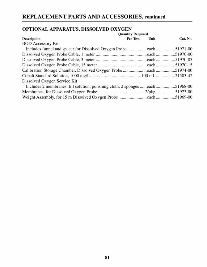
REPLACEMENT PARTS AND ACCESSORIES, continued
OPTIONAL APPARATUS, DISSOLVED OXYGENQuantity Required
Description Per Test Unit Cat. No.BOD Accessory Kit
Includes funnel and spacer for Dissolved Oxygen Probe .................each.................51971-00Dissolved Oxygen Probe Cable, 1 meter .............................................each.................51970-00Dissolved Oxygen Probe Cable, 3 meter .............................................each.................51970-03Dissolved Oxygen Probe Cable, 15 meter ...........................................each.................51970-15Calibration Storage Chamber, Dissolved Oxygen Probe .....................each.................51974-00Cobalt Standard Solution, 1000 mg/L.............................................100 mL.................21503-42Dissolved Oxygen Service Kit
Includes 2 membranes, fill solution, polishing cloth, 2 sponges ......each.................51968-00Membranes, for Dissolved Oxygen Probe ......................................... 2/pkg.................51973-00Weight Assembly, for 15 m Dissolved Oxygen Probe.........................each.................51969-00
81

HOW TO ORDER
By Telephone: By Mail:6:30 a.m. to 5:00 p.m. MST Hach CompanyMonday through Friday P.O. Box 389(800) 227-HACH Loveland, Colorado 80539-0389(800-227-4224) U.S.A.By FAX: Ordering information by E-mail:(970) 669-2932 [email protected]
Information Required
Technical and Customer Service (U.S.A. only)Hach Technical and Customer Service Department personnelare eager to answer questions about our products and their use.Specialists in analytical methods, they are happy to put theirtalents to work for you. Call 1-800-227-4224 or [email protected].
International CustomersHach maintains a worldwide network of dealers and distributors.To locate the representative nearest you, send E-mail tointl@hach. com or
In Canada:Hach Sales & Service Canada Ltd.; Manitoba, CanadaTelephone: (204) 632-5598; FAX: (204) 694-5134
• Hach account number (if available) • Billing address
• Your name and phone number • Shipping address
• Purchase order number • Catalog number
• Brief description or model number • Quantity
call (970) 669-3050.
82

REPAIR SERVICE
83

WARRANTY
84

CERTIFICATION
Hach Company certifies this instrument was tested thoroughly,inspected and found to meet its published specifications when itwas shipped from the factory.
The sension378™ Multiparameter Meter has been tested and iscertified as indicated to the following instrumentation standards:
Product SafetyExternal Power Supplies Only:
115 V ac Supply, UL Listed & CSA Certified or
230 V ac Supply, CE Marked per 73/23/EEC, VDE Listed
EMI ImmunityInstrument Tested with the external 230V, 50 Hz Power Supply:
Per 89/336/EEC EMC: EN 61326:1998 (ElectricalEquipment for measurement, control and laboratory use-EMC requirements) Supporting test records by HachCompany, certified compliance by Hach Company.
Standards IncludeIEC 1000-4-2:1995 (EN 61000-4-2:1995) Electro-StaticDischarge Immunity (Criteria C)
IEC 1000-4-3:1995 (EN 61000-4-3:1996) Radiated RF Electro-Magnetic Field Immunity (Criteria A)
IEC 1000-4-4:1995 (EN 61000-4-4:1995) Electrical FastTransients/Burst (Criteria B)
IEC 1000-4-5:1995 (EN 61000-4-5:1995) Surge (Criteria B)
IEC 1000-4-6:1996 (EN 61000-4-6:1996) ConductedDisturbances Induced by RF Fields (Criteria A)
IEC 1000-4-11:1994 (EN 61000-4-11:1994) Voltage Dip/ShortInterruptions (Criteria B)
85

CERTIFICATION, continued
Additional immunity Standard/s include:ENV 50204:1996 Radiated Electro-Magnetic Field from DigitalTelephones (Criteria A)
EmissionsInstrument Tested with the external 230V, 50 Hz Power Supply:
Per 89/336/EEC EMC: EN 61326:1998 (Electrical Equipmentfor measurement, control and laboratory use-EMC requirements)Class “B” emission limits. Supporting test records by HewlettPackard, Fort Collins, Colorado Hardware Test Center (A2LA #0905-01), certified compliance by Hach Company.
Standards include:EN 61000-3-2 Harmonic Disturbances Caused by ElectricalEquipment
EN 61000-3-3 Voltage Fluctuation (Flicker) DisturbancesCaused by Electrical Equipment
Additional Emissions Standard/s IncludeEN 55011 (CISPR 11), Class “B” emission limits
CANADIAN INTERFERENCE-CAUSING EQUIPMENTREGULATION, IECS-003: Class “A” emission limits.Supporting test records by Hewlett Packard, Fort Collins,Colorado Hardware Test Center (A2LA # 0905-01), certifiedcompliance by Hach Company.
This Class A digital apparatus meets all requirements of theCanadian Interference- Causing Equipment Regulations.
Cet appareil numérique de la classe A respecte toutes lesexigences du Règlement sur le matériel brouilleur du Canada.
FCC PART 15: Class emission “A” limits. Supporting testrecords by Hewlett Packard, Fort Collins, Colorado HardwareTest Center (A2LA # 0905-01), certified compliance byHach Company.
This device complies with Part 15 of the FCC Rules. Operation issubject to the following two conditions:
86

CERTIFICATION, continued
(1) this device may not cause harmful interference, and (2) thisdevice must accept any interference received, includinginterference that may cause undesired operation.
Changes or modifications to this unit not expressly approved bythe party responsible for compliance could void the user'sauthority to operate the equipment.
This equipment has been tested and found to comply with thelimits for a Class A digital device, pursuant to Part 15 of the FCCRules. These limits are designed to provide reasonable protectionagainst harmful interference when the equipment is operated in acommercial environment. This equipment generates, uses, andcan radiate radio frequency energy and, if not installed and usedin accordance with the instruction manual, may cause harmfulinterference to radio communications. Operation of thisequipment in a residential area is likely to cause harmfulinterference, in which case the user will be required to correct theinterference at his own expense. The following techniques ofreducing the interference problems are applied easily.
1. Disconnect the external power supply from the sension378Multiparameter Meter to verify that the meter is or is not thesource of the interference.
2. Move the sension378 Multiparameter Meter and its powersupply away from the device receiving the interference.
3. Reposition the receiving antenna for the device receivingthe interference.
4. Try combinations of the above.
87

HACH COMPANYWORLD HEADQUARTERSP.O. Box 389Loveland, Colorado 80539-0389Telephone: (970) 669-3050FAX: (970) 669-2932
FOR TECHNICAL ASSISTANCE, PRICE INFORMATION AND ORDERING:Call 800-227-4224
Contact the HACH office or distributor serving you.www.hach.com [email protected]
In the U.S.A. -Outside the U.S.A. -On the Worldwide Web - ; E-mail -
toll-free